Control Circuit for Driving Different Color Temperature LED Lights with AC Input Voltage
Abstract
A control circuit for driving different color temperatures LED lights with AC input voltage comprises a LED light set A with one color temperature; and a LED light set B with another color temperature; two AC input voltages L 1 and L 2 ; wherein the LED light sets A and B are arranged in parallel. Two different color temperatures LED light sets are used to generate three different color temperatures LED lights sources, which meets the requirement for using different LED color temperature light sources in different scenarios to reduce the inventory of different LED lights.
Claims (5)
1 . A control circuit for driving different color temperatures LED lights with AC input voltage, comprising: a first LED light set (A) with one color temperature; and a second LED light set (B) with another color temperature; two AC input voltages (L 1 and L 2 ); wherein the LED light sets (A and B) are arranged in parallel; the positive pole of the LED light sets (A and B) relate to the output of a step-down and constant current source circuit; the negative pole of the first LED light set (A) is connected with the anodes of first switch (Q 1 ), the negative pole of the second LED light set (B) is connected with the anodes of second switch (Q 2 ), the cathodes of the switches (Q 1 and Q 2 ) are connected with the output of a step-down and constant current source circuit; the two switches (Q 1 and Q 2 ) are arranged in parallel and controlled by a control circuit; wherein the control circuit drives either or both of the LED light sets (A and B) by the two switches (Q 1 and Q 2 ), thus to generate three different color temperatures, wherein the control circuit is comprising: two half-wave rectifier circuits; two optical couplers (OT 1 and OT 2 ); wherein the first half-wave rectifier circuit and first optical coupler (OT 1 are arranged between the AC input voltage (L 1 ) and the switch (Q 1 ) to control the first switch (Q 1 ); and the second half-wave rectifier circuit and second optical coupler (OT 2 ) are arranged between the AC input voltage (L 2 ) and the switch (Q 2 ) to control the second switch (Q 2 ).
Show 4 dependent claims
2 . The control circuit for driving different color temperatures LED lights with AC input voltage according to claim 1 , wherein when the AC input voltage (L 1 ) is connected to the first half-wave rectifier circuit, the control circuit turn on the first switch (Q 1 ) to drive the first LED light set (A); when the AC input voltage (L 2 ) is connected to the second half-wave rectifier circuit, the control circuit turn on the second switch (Q 2 ) to drive the second LED light set (B); and when both AC input voltages (L 1 and L 2 ) are connected to the first and second half-wave rectifier circuit, the control circuit turn on both switches (Q 1 and Q 2 ) to drive both LED light sets (A and B).
3 . The control circuit for driving different color temperatures LED lights with AC input voltage according to claim 1 , wherein when the AC input voltage (L 1 ) is connected to the control circuit, the control circuit turn on the first LED light set (A) to generate the first color temperature; when the AC input voltage (L 2 ) is connected to the control circuit, the control circuit turn on the second LED light set (B) to generate the second color temperature; and when both AC input voltages (L 1 and L 2 ) are connected to the control circuit, the control circuit turn on both LED light sets (A and B) to generate the mixed third color temperature.
4 . The control circuit for driving different color temperatures LED lights with AC input voltage according to claim 1 , wherein the first LED light set (A) is composed of a set of LED beads with one color temperature; and the LED second light set (B) is composed of a another set of LED beads with another color temperature.
5 . The control circuit for driving different color temperatures LED lights with AC input voltage according to claim 1 , wherein the control circuit drives two or more LED light sets with the same number of AC input voltages to generate three or more different color temperature.
Full Description
Show full text →
TECHNICAL FIELD
The present invention relates to LED lighting; and in particular to a control circuit for driving different color temperatures LED lights with AC input voltage.
BACKGROUND OF THE INVENTION
LED has the characteristics of energy conservation, environmental protection, long service life, small size, rich colors, flexible combination, strong vibration resistance, and no noise. LED lights are currently recognized as one of the environmentally friendly light sources. With the popularization of LED technology, LED lights have enriched the lighting market and made the functions of lighting more diversified. With the development of social productivity and the continuous improvement of people's living standards, the demand for LED lights with different color temperatures in different scenarios is also increasing. Because different scenarios require LED lights (or modules) with different color temperatures, there are too many kinds of LED lights which led to the problem of overproduction and excessive storage for manufacturers and difficulty in on-site installation.
SUMMARY OF THE INVENTION
The purpose of the present invention is to meet the requirement of using LED lights with different color temperatures in different scenarios. For this purpose, the present invention provides a control circuit for driving different color temperatures LED lights with AC input voltage, comprising: a LED light set A with one color temperature; and a LED light set B with another color temperature; two AC input voltages L 1 and L 2 ; wherein the LED light sets A and B are arranged in parallel; the positive pole of the LED light sets A and B are connected with the output of a step-down and constant current source circuit; the negative pole of the LED light set A is connected with the anodes of switch Q 1 , the negative pole of the LED light set B is connected with the anodes of switch Q 2 , the cathodes of the switches Q 1 and Q 2 are connected with the output of a step-down and constant current source circuit; the two switches Q 1 and Q 2 are arranged in parallel and controlled by a control circuit; wherein the control circuit drives either or both of the LED light sets A and B by the two switches Q 1 and Q 2 , thus to generate three different color temperatures. In some embodiments, the control circuits comprising: two half-wave rectifier circuits; two optical couplers OT 1 and OT 2 ; wherein the first half-wave rectifier circuit and an optical coupler OT 1 are arranged between the AC input voltage L 1 and the switch Q 1 to control the switch Q 1 ; and the second half-wave rectifier circuit and another optical coupler OT 2 are arranged between the AC input voltage L 2 and the switch Q 2 to control the switch Q 2 . In some embodiments, when the AC input voltage L 1 is connected to the first half-wave rectifier circuit, the control circuit turn on the switch Q 1 to drive the LED light set A; when the AC input voltage L 2 is connected to the second half-wave rectifier circuit, the control circuit turn on the switch Q 2 to drive the LED light set B; and when both AC input voltage L 1 and L 2 are connected to the first and second half-wave rectifier circuit, the control circuit turn on both switches Q 1 and Q 2 to drive both LED light sets A and B. In some embodiments, when the AC input voltage L 1 is connected to the control circuit, the control circuit turn on the LED light set A to generate the first color temperature; when the AC input voltage L 2 is connected to the control circuit, the control circuit turn on the LED light set B to generate the second color temperature; and when both AC input voltages L 1 and L 2 are connected to the control circuit, the control circuit turn on both LED light sets A and B to generate the mixed third color temperature. In some embodiments, the LED light set A is composed of a set of LED beads with one color temperature; and the LED light set B is composed of a set of LED beads with another color temperature. In some embodiments, the control circuit drives two or more LED light sets with the same number of AC input voltages to generate three or more different color temperature. The advantage of the present invention is using two different color temperatures LED light sets to generate three different color temperatures LED lights sources, which meets the requirement for using different LED color temperature light sources in different scenarios. Therefor manufacturers can reduce the inventory of different LED lights to save costs and to be more manageable. The usages can switch different color temperatures in different environmental scenarios which can enrich user experience.
BRIEF DESCRIPTION OF DRAWINGS
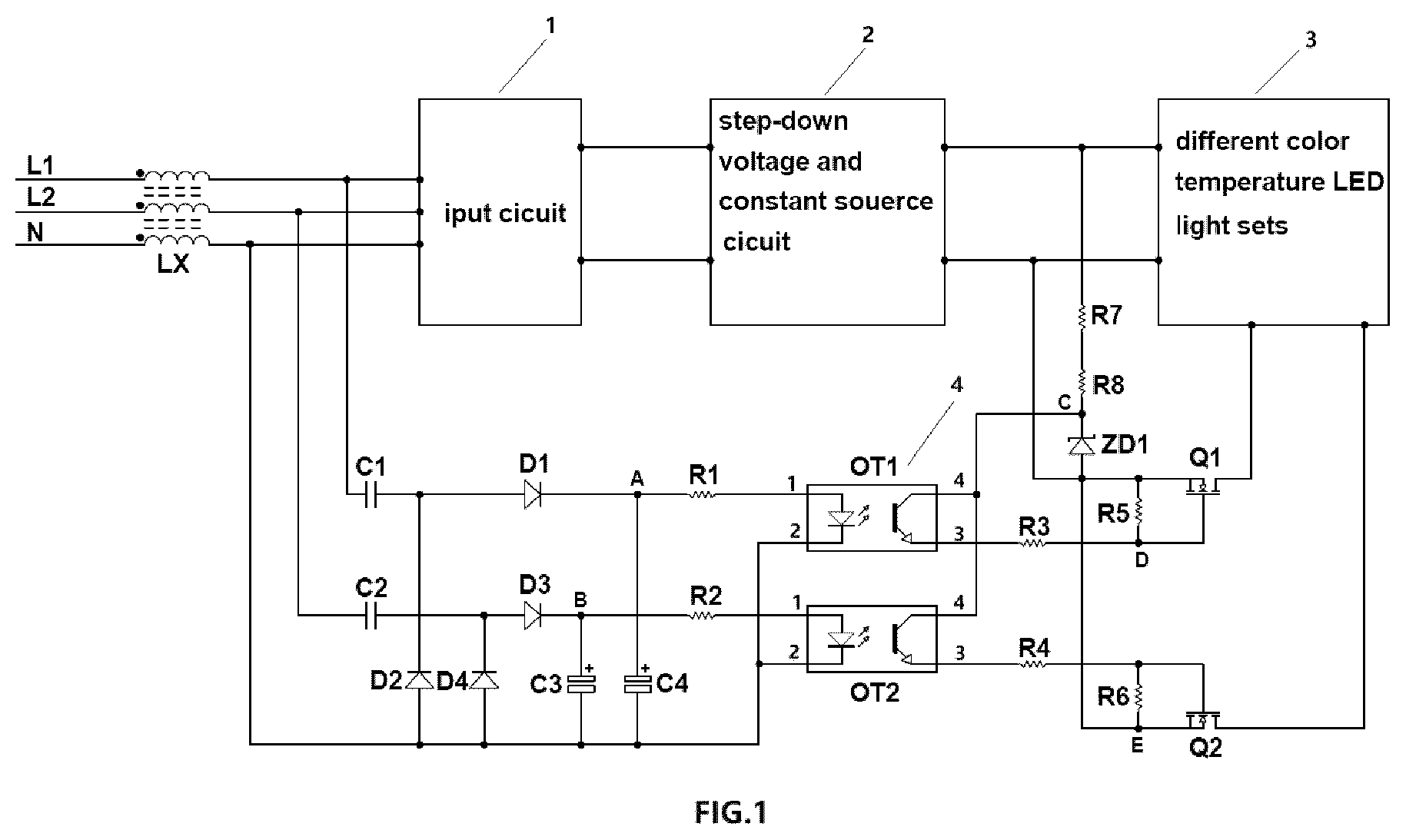
is an electrical block diagram of a control circuit for driving different color temperatures LED lights with AC input voltage, in an embodiment of the present invention. is a circuit schematic diagram of a control circuit for driving different color temperatures LED lights with AC input voltage, in an embodiment of the present invention. a circuit schematic diagram of the output of the step-down and constant current source circuit, in an embodiment of the present invention. EXPLANATION OF REFERENCE SIGNS 1 —Input circuit; 2 —output of the step-down and constant current source circuit; 3 —LED light sets with different color temperatures; 4 —control circuit.
DETAILED DESCRIPTION
OF THE INVENTION With reference to , 2 , and 3 , the input of input circuit 1 is connected with: L 1 : Live Wire input AC voltage L 1 : live Wire; L 2 : Live Wire; input AC voltage L 2 : live Wire; N: Neutral Wire; LX: three winding common mode inductance; Input circuit 1 is composed of rectification and filtering circuit and EMI circuit, etc., to output DC voltage. With reference to , the step-down and constant current source circuit is composed of a chip IC (model IW3627), MOS transistor Q, transformer T, rectifier transistor D and filter capacitor C, to output a constant current source voltage BUS+. Two LED light sets A and B with different color temperatures: The LED light set A is composed of LED beads LED 1 , LED 2 , LED 3 , . . . . LEDn 1 with one color temperature. The LED light set B is composed of LED beads LED 4 , LED 5 , LED 6 , . . . . LEDn 2 with another color temperature. The LED light sets A and B are arranged in parallel. The positive pole of the LED light sets A and B are connected with the output of the step-down and constant current source circuit 2 . The negative pole of the LED light set A relates to the anodes of switch Q 1 . The negative pole of the LED light set B relates to the anodes of switch Q 2 . The cathodes of the switches Q 1 and Q 2 are connected with the output of the step-down and constant current source circuit 2 . The Control Circuit: The AC input voltage L 1 is connected with the first half-wave rectifier circuit D 1 , D 2 C 4 . The output of the first half-wave rectifier circuit D 1 , D 2 . C 4 is connected to the input of the optical coupler OT 1 (model EL817 series) through the current limiting resistors R 1 . The output of the optical coupler OT 1 is connected to the grid electrode of the switch Q 1 . When the first half-wave rectifier circuit D 1 , D 2 . C 4 output high level to the optical coupler OT 1 to turn on the switch Q 1 , the negative pole of the LED light set A is connected with the output of the step-down and constant current source circuit 2 to turn on the LED light set A. The AC input voltage L 2 is connected with the first half-wave rectifier circuit D 3 . D 4 . C 3 . The output of the second half-wave rectifier circuit D 3 , D 4 . C 3 is connected to the input of the optical coupler OT 2 (model EL817 series) through the current limiting resistors R 2 . The output of the optical coupler OT 2 is connected to the grid electrode of the switch Q 2 . When the second half-wave rectifier circuit D 3 . D 4 . C 3 output high level to the optical coupler OT 2 to turn on the switch Q 2 , the negative pole of the LED light set B is connected with the output of the step-down and constant current source circuit 2 to turn on the LED light set B. The Working Process is as Follows: When the AC input voltage L 1 and neutral wire N are connected with the electric supply (L 2 is disconnected), the electric supply generate a constant voltage at the output of the step-down and constant current source circuit after passing through the rectification and filtering circuit in the input circuit and the step-down and constant current source circuit, then a constant voltage is generated at point C after passing through the current limiting resistors R 7 , R 8 and Zener diode ZD 1 . At the same time, the electric supply generate a constant voltage at point A after passing through diodes D 1 ,D 2 and capacitors C 1 ,C 4 in the first half-wave rectifier circuit to drive the LED on the primary side of the optical coupler OT 1 after passing through the current limiting resistor R 1 . After the photo transistor on the secondary side of the optical coupler OT 1 receives the optical signal from the primary side and turns it on, the voltage at point C generate a high level at the grid electrode of the switch Q 1 to turn on the switch Q 1 after being divided by the current limiting resistor R 3 and the bias resistor R 5 , then the LED light set A is lit up to generate the first color temperature. Similarly, When the AC input voltage L 2 and neutral wire N are connected with the electric supply (L 1 is disconnected), the LED light set B is lit up to generate the second color temperature. When both AC input voltages L 1 and L 2 and neutral wire N relate to the electric supply, both LED light sets A and B are lit up to generate the mixed third color temperature. In some embodiments, the control circuit drives two or more LED light sets with the same number of AC input voltages to generate three or more different color temperature.
Figures (3)
Citations
This patent cites (5)
- US10159131
- US10531534
- US2020/0214096
- US2022/0279636
- US114175858