Abstract
A connector assembly includes a first circuit board, a first connector, a second circuit board, a second connector, a plug, and a blocking portion. The first connector is disposed on the first circuit board. The first connector includes a first conductive terminal, a first busbar, and a first sleeve. The first busbar is connected to the first conductive terminal. The second connector is disposed on the second circuit board. The second connector includes a second conductive terminal, a second busbar, and a second sleeve. The second busbar is connected to the second conductive terminal. The second sleeve is connected to the second busbar. The plug passes through the first sleeve of the first connector and the second sleeve of the second connector. The blocking portion is disposed on the plug. A diameter of the blocking portion is greater than a diameter of the plug.
Claims (20)
1 . A connector assembly, comprising: a first circuit board; a first connector disposed on the first circuit board, comprising: a first conductive terminal; a first busbar connected to the first conductive terminal; and a first sleeve connected to the first busbar; a second circuit board separated from the first circuit board; a second connector disposed on the second circuit board, comprising: a second conductive terminal; a second busbar connected to the second conductive terminal; and a second sleeve connected to the second busbar; a plug passing through the first sleeve of the first connector and the second sleeve of the second connector; and a blocking portion disposed on the plug, and the blocking portion abutting against or being fixed to the first connector.
14 . A connector, comprising: a first housing having a first socket and a second socket separated from the first socket, the first socket being configured to allow an expansion card to insert; a plurality of first conductive terminals, wherein each of the first conductive terminals comprises a first end portion corresponding to the first socket and a second end portion corresponding to the second socket; a first busbar with one end located in the second socket connected to the second end portion; and a first sleeve connected to the other end of the first busbar and having a groove or a through hole that are hollowed.
Show 18 dependent claims
2 . The connector assembly of claim 1 , wherein the blocking portion abuts against a top portion of the first sleeve.
3 . The connector assembly of claim 1 , wherein the first connector further comprises a first housing wrapping the first conductive terminal and a first cover body wrapping the first busbar, wherein the first housing comprises a first barb, the first cover body comprises a first hook, and the first housing and the first cover body are respectively engaged with each other by the first barb and the first hook.
4 . The connector assembly of claim 3 , wherein the first housing further has a first socket and a second socket separated from the first socket, and wherein the first conductive terminal comprises a first end portion corresponding to the first socket and a second end portion corresponding to the second socket.
5 . The connector assembly of claim 4 , wherein the second end portion of the first conductive terminal clamps the first busbar.
6 . The connector assembly of claim 3 , wherein the first cover body further comprises: a first cover main body; a first top plate covering the first cover main body; and a first partitioning portion disposed between the first cover main body and the first top plate, wherein the first partitioning portion, the first cover main body, and the first top plate jointly define two accommodating cavities of the first cover body.
7 . The connector assembly of claim 6 , wherein the first sleeve is located in one of the two accommodating cavities and runs through the first cover main body and the first top plate.
8 . The connector assembly of claim 1 , wherein the first busbar comprises: one or more first vertical extending portions contacting the first conductive terminal; one or more first bending portions connected to the one or more first vertical extending portions; and a first horizontal extending portion connected to the one or more first bending portions.
9 . The connector assembly of claim 1 , further comprising a crown spring, wherein the first sleeve has a hollowed through hole, the crown spring surrounds an inner surface of the hollowed through hole, and the crown spring clamps the plug.
10 . The connector assembly of claim 1 , wherein the first sleeve comprises: a sleeve main body connected to the first busbar; a cap portion located on a top portion of the sleeve main body and bearing against a surface of the first busbar, and a diameter of the cap portion is greater than a diameter of the sleeve main body; and an interfering portion disposed on the sleeve main body, and the interfering portion being engaged with the first busbar.
11 . The connector assembly of claim 1 , wherein a width of the blocking portion is greater than a width of the plug.
12 . The connector assembly of claim 1 , wherein the first conductive terminal comprises a plurality of one of the following or a combination of the following that are fixed to each other: a fixed conductive terminal comprising a first end portion, a second end portion, a fixed portion, and a welding pin; and a floating conductive terminal comprising a first end portion, a second end portion, and a fixed portion.
13 . The connector assembly of claim 12 , wherein the first end portion, the second end portion, the fixed portion, and the welding pin of the fixed conductive terminal are coplanar.
15 . The connector of claim 14 , further comprising a crown spring surrounding an inner surface of the groove or the through hole.
16 . The connector of claim 14 , wherein the first busbar comprises: one or more first vertical extending portions contacting the second end portion; one or more first bending portions connected to the one or more first vertical extending portions; and a first horizontal extending portion connected to the one or more first bending portions.
17 . The connector of claim 14 , wherein each of the first conductive terminals comprises a plurality of one of the following or a combination of the following that are fixed to each other: a fixed conductive terminal comprising a first end portion, a second end portion, a fixed portion, and a welding pin; and a floating conductive terminal comprising a first end portion, a second end portion, and a fixed portion.
18 . The connector of claim 17 , wherein the first end portion, the second end portion, the fixed portion, and the welding pin of the fixed conductive terminal are coplanar.
19 . The connector of claim 14 , further comprising a cover body, wherein the cover body comprises two accommodating cavities, the two accommodating cavities are separated by a partitioning portion, and the first busbar is accommodated in one of the two accommodating cavities.
20 . The connector of claim 19 , wherein each of the two accommodating cavities has an opening for heat dissipation.
Full Description
Show full text →
CROSS-REFERENCE TO RELATED APPLICATION
This application claims priority to U.S. Provisional Application Ser. No. 63/622,547 filed Jan. 19, 2024, and Taiwan Application Serial Number 113140147, filed Oct. 22, 2024, the disclosures of which are incorporated herein by reference in their entireties.
BACKGROUND
Field of Invention The present invention relates to a connector assembly and a connector. Description of Related Art Generally speaking, a connector (e.g., a card-edge connector) for connecting with an expansion card is fixed on a circuit board (e.g., a motherboard). Therefore, when the user inserts the expansion card into the socket on the connector, the circuit board can build a connection of electrical signals (including receive/transmit current) with the expansion card. As the demand for transmitting large currents and the demand for connecting with multiple expansion cards at the same time increases, it is necessary to provide a hardware framework that can: accommodate multiple connectors simultaneously; ensure that the structure between multiple connectors is stable; and can simultaneously connect with different expansion cards. However, existing products fail to provide a connector assembly that satisfies users. Therefore, how to propose a connector assembly and a connector that can solve the aforementioned problems is one of the problems that the industry is currently eager to invest in research and development resources to solve.
SUMMARY
In view of this, one purpose of the present disclosure is to provide a connector assembly and a connector that can solve the aforementioned problems. In order to achieve the above objective, in accordance with an embodiment of the present disclosure, a connector assembly includes a first circuit board, a first connector, a second circuit board, a second connector, a plug, and a blocking portion. The first connector is disposed on the first circuit board. The first connector includes a first conductive terminal, a first busbar, and a first sleeve. The first busbar is connected to the first conductive terminal. The first sleeve is connected to the first busbar. The second circuit board is separated from the first circuit board. The second connector is disposed on the second circuit board. The second connector includes a second conductive terminal, a second busbar, a second sleeve. The second busbar is connected to the second conductive terminal. The second sleeve is connected to the second busbar. The plug passes through the first sleeve of the first connector and the second sleeve of the second connector. The blocking portion is disposed on the plug. The blocking portion abuts against or is fixed to the first connector. In one or more embodiments of the present disclosure, the blocking portion abuts against a top portion of the first sleeve. In one or more embodiments of the present disclosure, the first connector further includes a first housing wrapping the first conductive terminal and a first cover body wrapping the first busbar. The first housing includes a first barb. The first cover body includes a first hook. The first housing and the first cover body are respectively engaged with each other by the first barb and the first hook. In one or more embodiments of the present disclosure, the first housing further has a first socket and a second socket separated from the first socket. The first conductive terminal includes a first end portion corresponding to the first socket and a second end portion corresponding to the second socket. In one or more embodiments of the present disclosure, the second end portion of the first conductive terminal clamps the first busbar. In one or more embodiments of the present disclosure, the first cover body further includes a first cover main body, a first top plate, and a first partitioning portion. The first top plate covers the first cover main body. The first partitioning portion is disposed between the first cover main body and the first top plate. The first partitioning portion, the first cover main body, and the first top plate jointly define two accommodating cavities of the first cover body. In one or more embodiments of the present disclosure, the first sleeve is located in one of the two accommodating cavities and runs through the first cover main body and the first top plate. In one or more embodiments of the present disclosure, the first busbar includes the first busbar includes one or more first vertical extending portions, one or more first bending portions, and a first horizontal extending portion. One or more first vertical extending portions contact the first conductive terminal. One or more first bending portions are connected to the one or more first vertical extending portions. The first horizontal extending portion is connected to the one or more first bending portions. In one or more embodiments of the present disclosure, the connector assembly further includes a crown spring. The first sleeve has a hollowed through hole. The crown spring surrounds an inner surface of the hollowed through hole. The crown spring clamps the plug. In one or more embodiments of the present disclosure, the first sleeve includes a sleeve main body, a cap portion, and an interfering portion. The sleeve main body is connected to the first busbar. The cap portion is located on a top portion of the sleeve main body and bears against a surface of the first busbar. A diameter of the cap portion is greater than a diameter of the sleeve main body. The interfering portion is disposed on the sleeve main body. The interfering portion is engaged with the first busbar. In one or more embodiments of the present disclosure, a width of the blocking portion is greater than a width of the plug. In one or more embodiments of the present disclosure, the first conductive terminal includes a plurality of one of the following or a combination of the following that are fixed to each other: a fixed conductive terminal including a first end portion, a second end portion, a fixed portion, and a welding pin; and a floating conductive terminal including a first end portion, a second end portion, and a fixed portion. In one or more embodiments of the present disclosure, the first end portion, the second end portion, the fixed portion, and the welding pin of the fixed conductive terminal are coplanar. In order to achieve the above objective, in accordance with an embodiment of the present disclosure, a connector includes a first housing, a plurality of first conductive terminals, a first busbar, and a first sleeve. The first housing has a first socket and a second socket separated from the first socket. The first socket is configured to allow an expansion card to insert. Each of the first conductive terminals includes a first end portion corresponding to the first socket and a second end portion corresponding to the second socket. The first busbar with one end located in the second socket is connected to the second end portion. The first sleeve is connected to the other end of the first busbar and has a groove or a through hole that are hollowed. In one or more embodiments of the present disclosure, the connector further includes a crown spring surrounding an inner surface of the groove or the through hole. In one or more embodiments of the present disclosure, the first busbar includes one or more first vertical extending portions, one or more first bending portions, and a first horizontal extending portion. The one or more first vertical extending portions contact the second end portion. The one or more first bending portions are connected to the one or more first vertical extending portions. The first horizontal extending portion is connected to the one or more first bending portions. In one or more embodiments of the present disclosure, each of the first conductive terminals includes a plurality of one of the following or a combination of the following that are fixed to each other: a fixed conductive terminal including a first end portion, a second end portion, a fixed portion, and a welding pin; and a floating conductive terminal including a first end portion, a second end portion, and a fixed portion. In one or more embodiments of the present disclosure, the first end portion, the second end portion, the fixed portion, and the welding pin of the fixed conductive terminal are coplanar. In one or more embodiments of the present disclosure, connector further includes a cover body. The cover body includes two accommodating cavities. The two accommodating cavities are separated by a partitioning portion. The first busbar is accommodated in one of the two accommodating cavities. In one or more embodiments of the present disclosure, each of the two accommodating cavities has an opening for heat dissipation. In summary, in the connector assembly and connector of the present disclosure, since the first cover body and the first housing are engaged with each other by the first hook and the first barb respectively, the connection structure among the first conductive terminal, the first busbar, and the first sleeve can be stable, thereby ensuring the stability of the overall structure of the first connector. In the connector assembly and connector of the present disclosure, since the second cover body and the second housing are also engaged with each other by the second hook and the second barb respectively, the connection structure among the second conductive terminal, the second busbar, and the second sleeve can be stable, thereby ensuring the stability of the overall structure of the second connector. In the connector assembly and connector of the present disclosure, since the plug passes through the first sleeve of the first connector and the second sleeve of the second connector at the same time, the electrical signals of the expansion card read by the second circuit board can be transmitted to the first circuit board by the plug, thereby achieving connection of electrical signals from different expansion cards with different connectors. In the connector assembly and connector of the present disclosure, since the blocking portion is disposed in the middle section of the plug, and the diameter of the blocking portion is greater than the diameter of the plug, the second connector is separated from the first connector by a distance, thereby achieving the structural ability of the first connector and the second connector in the connector assembly. In the connector assembly and connector of the present disclosure, since the inner surface of the first sleeve and the inner surface of the second sleeve are surrounded by the crown spring, the crown spring can not only increase the contact area between the plug and the first sleeve and between the plug and the second sleeve to meet the demand for transmitting large currents, the crown spring also provides a positive force between the plug and the first sleeve and between the plug and the second sleeve to achieve auxiliary fixation between the second connector and the plug. Overall, the connector assembly of the present disclosure can not only connect electrical signals from a plurality of expansion cards on a plurality of connectors in series, but also achieve structural stability of the plurality of connectors in the overall connector assembly. It is to be understood that both the foregoing general description and the following detailed description are by examples, and are intended to provide further explanation of the invention as claimed.
BRIEF DESCRIPTION OF THE DRAWINGS
The invention can be more fully understood by reading the following detailed description of the embodiment, with reference made to the accompanying drawings as follows: is a perspective view of a connector assembly in accordance with an embodiment of the present disclosure; is a perspective view of the connector assembly in accordance with an embodiment of the present disclosure; is an exploded view of the connector assembly in accordance with an embodiment of the present disclosure; is a perspective view of a conductive terminal in accordance with an embodiment of the present disclosure; A is a schematic view of a fixed conductive terminal in accordance with an embodiment of the present disclosure; B is a schematic view of a floating conductive terminal in accordance with an embodiment of the present disclosure; is a top view of a cover body in accordance with an embodiment of the present disclosure; is a cross-sectional schematic view of a sleeve, a plug, and a crown spring in accordance with an embodiment of the present disclosure; is an exploded view of the connector assembly in accordance with an embodiment of the present disclosure; is a perspective view of the connector assembly in accordance with an embodiment of the present disclosure; is a perspective view of the connector assembly in accordance with another embodiment of the present disclosure; is a cross-sectional schematic view of a connector in accordance with an embodiment of the present disclosure; and is a perspective view of the connector assembly in accordance with yet another embodiment of the present disclosure.
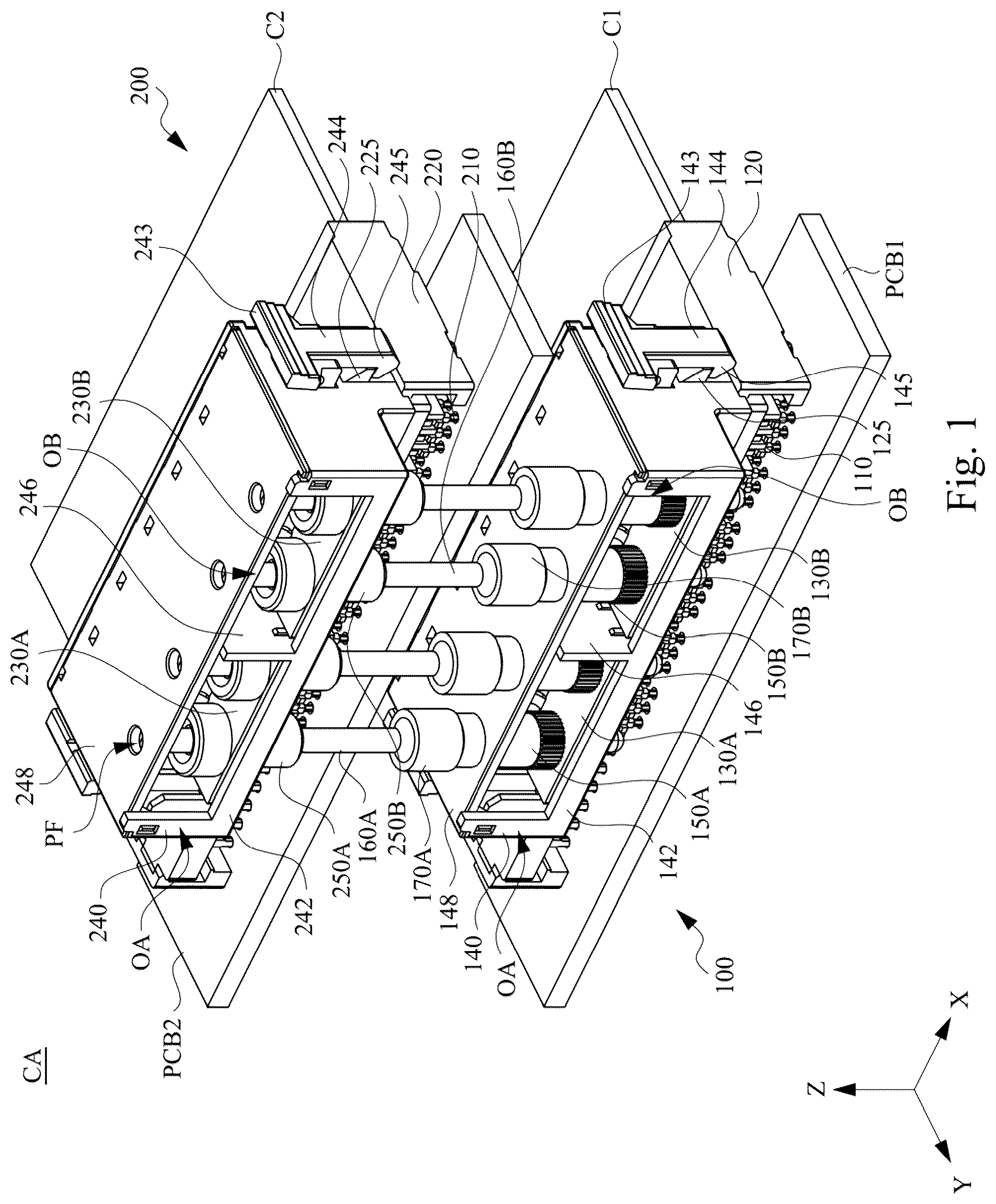
DETAILED DESCRIPTION
Hereinafter, a plurality of embodiments of the present disclosure will be disclosed in diagrams. For the sake of clarity, many details in practice will be described in the following description. However, it should be understood that these details in practice should not limit present disclosure. In other words, in some embodiments of present disclosure, these details in practice are unnecessary. In addition, for simplicity of the drawings, some conventionally used structures and elements will be shown in a simple schematic manner in the drawings. The same reference numbers are used in the drawings and the description to refer to the same or like parts. Hereinafter, the structure and function of each component included in a connector assembly CA of this embodiment and the connection relationship between the components will be described in detail. Reference is made to . is a perspective view of a connector assembly CA in accordance with an embodiment of the present disclosure. As shown in , in this embodiment, the connector assembly CA includes a circuit board PCB 1 , a connector 100 , a circuit board PCB 2 , a connector 200 , a plug 160 A, a plug 160 B, a blocking portion 170 A, and a blocking portion 170 B. The connector 100 is disposed on the circuit board PCB 1 . The connector 200 is disposed on the circuit board PCB 2 . The circuit board PCB 1 and the circuit board PCB 2 are independently separated from each other. In some embodiments, the circuit board PCB 2 is located over the circuit board PCB 1 , and the circuit board PCB 1 and the circuit board PCB 2 are parallel to each other. The connector 100 is configured to allow an expansion card C 1 to insert, and the connector 200 is configured to allow the expansion card C 2 to insert. The plugs 160 A and 160 B may be cylinders and are electrically connected to the connector 100 and the connector 200 . By the aforementioned structural configuration, when the expansion card C 1 is inserted into the connector 100 and the expansion card C 2 is inserted into the connector 200 , the connector 200 can transmit the electrical signals of the expansion card C 2 to the circuit board PCB 2 and to the circuit board PCB 1 by the plug 160 A and the plug 160 B. Accordingly, the connector assembly CA can transmit electrical signals of the expansion card C 1 and the electrical signals of the expansion card C 2 in parallel, and simultaneously obtain the electrical signals of the expansion card C 1 and the electrical signals of the expansion card C 2 to the circuit board PCB 1 . Reference is made again to . As shown in , in this embodiment, the connector 100 includes a conductive terminal 110 , a housing 120 , a busbar 130 A, a busbar 130 B, a cover body 140 , a sleeve 150 A, and a sleeve 150 B. The housing 120 wraps a plurality of conductive terminals 110 . The housing 120 has at least one socket configured to allow the expansion card C 1 to insert. The plurality of conductive terminals 110 are disposed on the circuit board PCB 1 , and a part of the plurality of conductive terminals 110 is located in the at least one socket for docking with the expansion card C 1 . The busbar 130 A and the busbar 130 B are connected to the plurality of conductive terminals 110 . The cover body 140 wraps the busbar 130 A and the busbar 130 B. The sleeve 150 A and the sleeve 150 B are respectively connected to the busbar 130 A and the busbar 130 B and have grooves or through holes that are hollowed. As shown in , the housing 120 includes a barb 125 . The cover body 140 includes a cover main body 142 , a buckle structure, and a top plate 148 . The buckle structure is configured to be buckled with the barb 125 . The buckle structure includes a pressing portion 143 , a connecting arm 144 , and a hook 145 . The pressing portion 143 is disposed on a side surface of the cover main body 142 . The pressing portion 143 and the hook 145 are located at both ends of the connecting arm 144 . In other words, the connecting arm 144 is connected between the hook 145 and the pressing portion 143 . The pressing portion 143 and the hook 145 seesaw relative to the cover main body 142 . The top plate 148 covers the cover main body 142 . The cover body 140 may also include a partitioning portion 146 disposed between the cover main body 142 and the top plate 148 configured to electrically isolate the busbar 130 A and the busbar 130 B. The partitioning portion 146 , the cover main body 142 , and the top plate 148 jointly define two accommodating cavities configured to respectively accommodate the busbar 130 A and the busbar 130 B. The accommodating cavities respectively form an opening OA and an opening OB on the cover body 140 . In detail, the partitioning portion 146 divides a space formed by the cover main body 142 and the top plate 148 into the two accommodating cavities that have the opening OA and the opening OB respectively for heat dissipation. As shown in , the housing 120 and the cover body 140 are engaged with each other by the barb 125 and the hook 145 , respectively. The sleeve 150 A and the sleeve 150 B are respectively located in the two accommodating cavities of the cover body 140 . The sleeve 150 A and the sleeve 50 B run through the cover main body 142 and the top plate 148 . Reference is made again to . As shown in , in this embodiment, the connector 200 includes a conductive terminal 210 , a housing 220 , a busbar 230 A, a busbar 230 B, a cover body 240 , a sleeve 250 A, and a sleeve 250 B. The housing 220 wraps a plurality of conductive terminals 210 . The housing 220 has at least one socket configured to allow the expansion card C 2 to insert. The plurality of conductive terminals 210 are disposed on the circuit board PCB 2 , and a part of the plurality of conductive terminals 210 is located in the at least one socket for docking with the expansion card C 2 . The busbar 230 A and the busbar 230 B are connected to the plurality of conductive terminals 210 . The cover body 240 wraps the busbar 230 A and the busbar 230 B. The sleeve 250 A and the sleeve 250 B are respectively connected to the busbar 230 A and the busbar 230 B. As shown in , the housing 220 includes a barb 225 . The cover body 240 includes a cover main body 242 , a buckle structure, and a top plate 248 . The buckle structure is configured to be buckled with the barb 225 . The buckle structure includes a pressing portion 243 , a connecting arm 244 and a hook 245 . The pressing portion 243 is disposed on a side surface of the cover main body 242 . The pressing portion 243 and the hook 245 are located at both ends of the connecting arm 244 . In other words, the connecting arm 244 is connected between the hook 245 and the pressing portion 243 . The pressing portion 243 and the hook 245 seesaw relative to the cover main body 242 . The top plate 248 covers the cover main body 242 . The cover body 240 may also include a partitioning portion 246 disposed between the cover main body 242 and the top plate 248 to electrically isolate the busbar 230 A and the busbar 230 B. The partitioning portion 246 , the cover main body 242 , and the top plate 248 jointly define two accommodating cavities to respectively accommodate the busbar 230 A and the busbar 230 B. The accommodating cavities respectively form an opening OA and an opening OB on the cover body 240 . In detail, the partitioning portion 246 divides a space formed by the cover main body 242 and the top plate 248 into the two accommodating cavities that have the opening OA and the opening OB respectively for heat dissipation. As shown in , the housing 220 and the cover body 240 are engaged with each other by the barb 225 and the hook 245 , respectively. The sleeve 250 A and the sleeve 250 B are respectively located in the two accommodating cavities of the cover body 240 . The sleeve 250 A and the sleeve 250 B run through the cover main body 242 . As shown in , the top plate 248 of the cover body 240 has a plurality of perforations PF for the plug 160 A and the plug 160 B to pass through. Reference is made again to . As shown in , in this embodiment, the plug 160 A passes through the sleeve 150 A of the connector 100 and the sleeve 250 A of the connector 200 . The plug 160 B passes through the sleeve 150 B of the connector 100 and the sleeve 250 B of the connector 200 . Please also refer to . The blocking portion 170 A is disposed on the plug 160 A. The blocking portion 170 B is disposed on the plug 160 B. The blocking portion 170 A may be integrally formed with the plug 160 A. The blocking portion 170 B may be integrally formed with the plug 160 B. In detail, the blocking portion 170 A and the blocking portion 170 B are respectively located at a middle section of the plug 160 A and a middle section of the plug 160 B. In some embodiments, a distance between the blocking portion 170 A and an end of the plug 160 A may be shorter than a distance between the blocking portion 170 A and the other end of the plug 160 A, and a distance between the blocking portion 170 B and an end of the plug 160 B may be shorter than a distance between the blocking portion 170 B and the other end of the plug 160 B. In some embodiments, a diameter of the blocking portion 170 A is greater than a diameter of the plug 160 A and a diameter of the hollowed grooves or through holes of the sleeve 150 A, and a diameter of the blocking portion 170 B is greater than a diameter of the plug 160 B and a diameter of the hollowed grooves or through holes of the sleeve 150 B. In some other embodiments, the blocking portion 170 A and the blocking portion 170 B are structures protruding from outer surfaces of the plug 160 A and the plug 160 B respectively, so that a width of the blocking portion 170 A and a width of the blocking portion 170 B are respectively greater than a width of the plug 160 A and a width of the plug 160 B, and the width of the blocking portion 170 A and the width of the blocking portion 170 B are also greater than a width of the hollowed grooves or hollowed through holes of the sleeve 150 A and the sleeve 150 B. This ensures that the blocking portion 170 A abuts against a top portion of the sleeve 150 A when the plug 160 A passes through the sleeve 150 A from top to bottom and the blocking portion 170 B abuts against a top portion of the sleeve 150 B when the plug 160 B passes through the sleeve 150 B from top to bottom, so that the plug 160 A and the plug 160 B are stationary relative to the connector 100 . In some embodiments, the connector 100 and the connector 200 may be, for example, a card-edge connector or other similar connector. In some embodiments, the circuit board PCB 1 is configured as a mother board in the connector assembly CA, and the circuit board PCB 2 is configured as a secondary board in the connector assembly CA. In this case, the connector assembly CA can receive the electrical signals of the expansion card C 2 to the circuit board PCB 1 serving as the mother board by the plug 160 A and the plug 160 B, so as to simultaneously process (receive) the electrical signals of the expansion card C 1 and the electrical signals of the expansion card C 2 . In some other embodiments, both the circuit board PCB 1 and the circuit board PCB 2 can be configured as secondary boards in the connector assembly CA. In this case, the connector assembly CA can simultaneously receive the electrical signals of the expansion card C 2 and the electrical signals of the expansion card C 1 by the plug 160 A and the plug 160 B, and then connect the electrical signals to the mother board, so as to simultaneously process the electrical signals of the expansion card C 1 and the electrical signals of the expansion card C 2 . In some embodiments, the busbar 130 A and the busbar 230 A are configured as positive busbars, and the busbar 130 B and the busbar 230 B are configured as negative busbars. Therefore, the sleeve 150 A, the plug 160 A, and the sleeve 250 A are configured to output a current to the circuit board PCB 1 and the circuit board PCB 2 , whereas the sleeve 150 B, the plug 160 B, and the sleeve 250 B are configured to receive a current from the circuit board PCB 1 and the circuit board PCB 2 . In some embodiments, as shown in , two sleeves 150 A and two sleeves 150 B are arranged along a direction (e.g., x-direction). The two sleeves 250 A and the two sleeves 250 B are arranged along a direction (e.g., x-direction). Two plugs 160 A and two plugs 160 B are also arranged along a direction (e.g., x-direction). In some embodiments, the connector assembly CA as shown in includes two plugs 160 A and two plugs 160 B. Each of the plugs 160 A and each of the plugs 160 B are configured to carry a current of approximately 60 amps or more. In other words, the connector assembly CA as shown in can collectively carry a current of approximately 240 amps or more. In some embodiments, the housing 120 , the cover body 140 , the housing 220 , and the cover body 240 may be made of insulating materials. In some embodiments, the housing 120 , the cover body 140 , the housing 220 , and the cover body 240 may be, for example, plastic, rubber or other suitable dielectric materials. However, the present disclosure is not intended to limit the materials of the housing 120 , the cover body 140 , the housing 220 , and the cover body 240 . In some embodiments, the conductive terminals 110 , the busbar 130 A, the busbar 130 B, the sleeve 150 A, the sleeve 150 B, the plug 160 A, the plug 160 B, the blocking portion 170 A, the blocking portion 170 B, the conductive terminal 210 , the busbar 230 A, the busbar 230 B, the sleeve 250 A, and the sleeve 250 B may be made of conductive material. In some embodiments, the conductive terminal 110 , the busbar 130 A, the busbar 130 B, the sleeve 150 A, the sleeve 150 B, the plug 160 A, the plug 160 B, the blocking portion 170 A, the blocking portion 170 B, the conductive terminal 210 , the busbar 230 A, the busbar 230 B, the sleeve 250 A, and the sleeve 250 B may be, for example, copper or other suitable metal or conductive material. However, the present disclosure is not intended to limit the materials of the conductive terminal 110 , the busbar 130 A, the busbar 130 B, the sleeve 150 A, the sleeve 150 B, the plug 160 A, the plug 160 B, the blocking portion 170 A, the blocking portion 170 B, the conductive terminal 210 , the busbar 230 A, the busbar 230 B, the sleeve 250 A, and the sleeve 250 B. Reference is made to . is a perspective view of a connector assembly CA in accordance with an embodiment of the present disclosure. For simplicity, the cover body 140 and the cover body 240 are omitted in with respect to . As shown in , in this embodiment, the housing 120 has a socket 121 on a side of the housing 120 and a socket 122 separated from the socket 121 on the other side of the housing 120 . The socket 121 is configured to allow the expansion card C 1 to insert along a direction (e.g., y-direction), and the expansion card C 1 contacts the conductive terminal 110 . The socket 122 is configured to allow an end of the busbar 130 A and an end of the busbar 130 B to insert along a direction (e.g., negative-z-direction), and the busbar 130 A and the busbar 130 B respectively contact the corresponding conductive terminals 110 in the housing 120 . Similarly, the housing 220 has a socket 221 on a side of the housing 220 and a socket 222 separated from the socket 221 on the other side of the housing 220 . The socket 221 is configured to allow the expansion card C 2 to insert along a direction (e.g., y-direction), and the expansion card C 2 contacts the conductive terminal 210 . The socket 222 is configured to allow an end of the busbar 230 A and an end of the busbar 230 B to insert along a direction (e.g., negative-z-direction), and the busbar 230 A and the busbar 230 B respectively contact the corresponding conductive terminals 210 in the housing 220 . Reference is made again to . As shown in , in this embodiment, each of the busbar 130 A and the busbar 130 B includes one or more vertical extending portions 132 , one or more bending portions 134 , and a horizontal extending portion 136 . The one or more vertical extending portions 132 contact the conductive terminals 110 . The one or more bending portions 134 are connected to the one or more vertical extending portions 132 . The horizontal extending portion 136 is connected to the one or more bending portions 134 . The one or more bending portions 134 may have positioning structures (e.g., recesses) to facilitate positioning of the busbar 130 A and the busbar 130 B when the busbar 130 A and the busbar 130 B are installed in the housing 120 . In detail, the one or more vertical extending portions 132 contact the conductive terminals 110 . The horizontal extending portions 136 of the busbar 130 A and the busbar 130 B respectively contact the sleeve 150 A and the sleeve 150 B. Similarly, each of the busbar 230 A and the busbar 230 B includes one or more vertical extending portions 232 , one or more bending portions 234 , and a horizontal extending portion 236 . The one or more vertical extending portions 232 contact the conductive terminals 210 . The one or more bending portions 234 are connected to the one or more vertical extending portions 232 . The horizontal extending portion 236 is connected to the one or more bending portions 234 . The one or more bending portions 234 may have positioning structures (e.g., recesses) to facilitate positioning of the busbar 230 A and the busbar 230 B when the busbar 230 A and the busbar 230 B are installed in the housing 220 . In detail, the one or more vertical extending portions 232 contact the conductive terminals 210 . The horizontal extending portions 236 of the busbar 230 A and the busbar 230 B respectively contact the sleeve 250 A and the sleeve 250 B. Reference is made to . is an exploded view of the connector assembly CA in accordance with an embodiment of the present disclosure. As shown in , in this embodiment, the plug 160 A and the plug 160 B are extended along a direction (e.g., z-direction). A portion of the plug 160 A that is lower than the blocking portion 170 A passes through the sleeve 150 A, and a portion of the plug 160 A that is higher than the blocking portion 170 A is configured to pass through the sleeve 250 A. Similarly, a portion of the plug 160 B that is lower than the blocking portion 170 B passes through the sleeve 150 B, and a portion of the plug 160 B that is higher than the blocking portion 170 B is configured to pass through the sleeve 250 B. A plurality of perforations PF may be formed on the top plate 248 and are aligned with the hollowed through holes of the sleeve 250 A and the sleeve 250 B in a vertical direction. A diameter of the perforations PF can be slightly greater than a diameter of the end of the plug 160 A and the plug 160 B, so that portions of the plug 160 A and the plug 160 B that pass through the sleeve 250 A and the sleeve 250 B can also pass through the perforations PF, thereby the plug 160 A and the plug 160 B cooperating with applications of different spacing between the circuit board PCB 1 and the circuit board PCB 2 . Reference is made again to . In a usage scenario, firstly, the user can install the conductive terminals 110 and the housing 120 on the circuit board PCB 1 . Next, the user installs the busbar 130 A, the busbar 130 B, the sleeve 150 A, the sleeve 150 B, and the cover body 140 on the housing 120 , and enables the cover body 140 to be engaged with the housing 120 . Next, the user can install the conductive terminals 210 and the housing 220 on the circuit board PCB 2 . Next, the user installs the busbar 230 A, the busbar 230 B, the sleeve 250 A, the sleeve 250 B, and the cover body 240 on the housing 220 , and enables the cover body 240 to be engaged with the housing 220 . Next, the user installs the plug 160 A on the sleeve 150 A, and also installs the plug 160 B on the sleeve 150 B, and allows the blocking portion 170 A and the blocking portion 170 B to respectively abut against a top portion of the sleeve 150 A and a top portion of the sleeve 150 B. Next, the user installs the connector 200 disposed on the circuit board PCB 2 to the plug 160 A and the plug 160 B, allows the plug 160 A to pass through the sleeve 250 A, and allows the plug 160 B to pass through the sleeve 250 B. Finally, the user fixes the circuit board PCB 2 to a chassis (not shown), thereby completing the assembly of the connector assembly CA as shown in to . In some embodiments, the blocking portion 170 A and the blocking portion 170 B can abut against or be fixed on the connector 100 . For example, the blocking portion 170 A and the blocking portion 170 B abut against a top surface of the cover body 140 or buckle to be fixed on the cover body 140 . Reference is made to . is a perspective view of the conductive terminal 110 in accordance with an embodiment of the present disclosure. It should be noted that since the structures of the conductive terminal 110 and the conductive terminal 210 are exactly the same, only the conductive terminal 110 will be described in detail herein. As shown in , in this embodiment, the conductive terminal 110 includes a fixed conductive terminal 110 A and a floating conductive terminal 110 B. The fixed conductive terminal 110 A and the floating conductive terminal 110 B are fixed to each other. The conductive terminal 110 includes a first end portion 111 , a second end portion 112 separated from the first end portion 111 , and a fixed structure 113 configured to fix the fixed conductive terminal 110 A and the floating conductive terminal 110 B. The fixed structure 113 is connected between the first end portion 111 and the second end portion 112 . The first end portion 111 defines a first recessed portion T 1 and the second end portion 112 defines a second recessed portion T 2 . The first end portion 111 corresponds to the socket 121 and the second end portion 112 corresponds to the socket 122 . In this embodiment, as the expansion card C 1 is inserted into the socket 121 of the housing 120 , the first end portion 111 of the conductive terminal 110 clamps the expansion card C 1 so that the expansion card C 1 is accommodated in the first recessed portion T 1 . As the busbar 130 A and the busbar 130 B are inserted into the socket 122 of the housing 120 , the second end portion 112 of the conductive terminal 110 clamps the vertical extending portions 132 of the busbar 130 A and the busbar 130 B so that portions of the vertical extending portions 132 can be accommodated in the second recessed portion T 2 . As shown in , the fixed conductive terminal 110 A and the floating conductive terminal 110 B are substantially conformal. The difference in between is that the fixed conductive terminal 110 A further includes a welding pin 114 compared with the floating conductive terminal 110 B, and the welding pin 114 is connected to the fixed structure 113 . The detailed structures of the fixed conductive terminals 110 A and the floating conductive terminals 110 B will be described below. Reference is made to A and B . A is a schematic view of the fixed conductive terminal 110 A in accordance with an embodiment of the present disclosure. B is a schematic view of the floating conductive terminal 110 B in accordance with an embodiment of the present disclosure. As shown in A and B , in this embodiment, the fixed conductive terminal 110 A includes a first end portion 111 A, a second end portion 112 A, a fixed portion 113 A and the welding pin 114 . The fixed conductive terminal 110 A may be integrally formed, and the first end portion 111 A, the second end portion 112 A, the fixed portion 113 A, and the welding pin 114 are coplanar. The first end portion 111 A and the second end portion 112 A respectively define the first recessed portion T 1 and the second recessed portion T 2 . The fixed conductive terminal 110 A is welded to the circuit board PCB 1 by the welding pin 114 . The floating conductive terminal 110 B includes a first end portion 111 B, a second end portion 112 B, and a fixed portion 113 B. The floating conductive terminal 110 B may be integrally formed, and the first end portion 111 B, the second end portion 112 B, and the fixed portion 113 B are coplanar. The first end portion 111 B and the second end portion 112 B respectively define the first recessed portion T 1 and the second recessed portion T 2 . The fixed conductive terminal 110 A and the floating conductive terminal 110 B are fixed to each other by riveting the fixed portion 113 A and the fixed portion 113 B, respectively. By such structural design, a contact area of the conductive terminal 110 can be increased to conduct more current. In detail, the contact area of each of the conductive terminals 110 contacting the expansion card C 1 in the socket 121 is widened, and the contact area of each of the conductive terminals 110 contacting the vertical extending portions 132 in the socket 122 is also widened. As shown in , A , and B , since merely the fixed conductive terminal 110 A includes the welding pin 114 , when the conductive terminal 110 is disposed on the circuit board PCB 1 , the fixed conductive terminal 110 A directly contacts the circuit board PCB 1 and the floating conductive terminal 110 B does not directly contact the circuit board PCB 1 . In some embodiments, the conductive terminal 110 may include a plurality of fixed conductive terminals 110 A fixed to each other or a plurality of floating conductive terminals 110 B fixed to each other (that is, the electrical signals of the expansion card does not reach the circuit board where the connector is located). In some embodiments, the terminals of one of the connector 100 and the connector 200 may be two or more floating conductive terminals 110 B fixed to each other, whereas the terminals of the other connector may be fixed conductive terminals 110 A, so that the electrical signals of the expansion card C 1 and the expansion card C 2 are collectively provided to one of the circuit board PCB 1 and the circuit board PCB 2 . Reference is made to . is a top view of the cover body 140 in accordance with an embodiment of the present disclosure. For simplicity, the top plate 148 is omitted in . It should be noted that since the structures of the cover body 140 and the cover body 240 are similar, only the cover body 140 is taken as an example for detailed description herein. As shown in , in this embodiment, the cover main body 142 of the cover body 140 further has a plurality of slots SL and a plurality of holes H. The slots SL are configured to allow the busbar 130 A and the busbar 130 B to pass through. The holes H are configured to allow the sleeve 150 A and the sleeve 150 B to pass through. In some embodiments, the sleeve 150 A and the sleeve 150 B are respectively fixed on the cover body 140 by friction between the sleeve 150 A and an inner surface of the opening H and the friction of the sleeve 150 B and the inner surface of the opening H. In some embodiments, the cover main body 142 further includes a plurality of positioning parts BP (e.g., bumps) to mate with the positioning structures of the bending portions 134 of the busbar 130 A and the busbar 130 B, thereby positioning the busbars 130 A and the busbars 130 B. 130 B is positioned within the cover body 140 . Reference is made to . is a cross-sectional schematic view of the sleeve 250 B, the plug 160 B, and a crown spring CY in accordance with an embodiment of the present disclosure. For simplicity, the housing 220 and the cover body 240 are omitted in . As shown in , in this embodiment, the connector assembly CA further includes the crown spring CY surrounding an inner surface of the hollowed through hole of the sleeve 150 A, an inner surface of the hollowed through hole of the sleeve 150 B, and an inner surface of the hollowed through hole of the sleeve 250 A, and an inner surface of the hollowed through hole of the sleeve 250 B. It should be noted that since the connection relationships between the sleeve 150 A and the plug 160 A, the sleeve 250 A and the plug 160 A, the sleeve 150 B and the plug 160 B, and the sleeve 250 B and the plug 160 B are similar, only the sleeve 250 B and the plug 160 B will be described in detail herein as examples. As shown in , the crown spring CY clamps the plug 160 B. The crown spring CY contacts the sleeve 250 B and the plug 160 B. Reference is made again to . As shown in , in this embodiment, the conductive terminal 210 includes a first end portion 211 and a second end portion 212 separated from the first end portion 211 . The first end portion 211 corresponds to the socket 221 of the housing 220 and the second end portion 212 corresponds to the socket 222 of the housing 220 (not shown in ). As shown in and , in this embodiment, when the expansion card C 2 is inserted into the socket 221 of the housing 220 , the first end portion 211 of the conductive terminal 210 clamps the expansion card C 2 and allows a portion of the expansion card C 2 is accommodated in the first recessed portion T 1 . When the busbar 230 A and the busbar 230 B are inserted into the socket 222 of the housing 220 , the second end portion 212 of the conductive terminal 210 clamps the vertical extending portions 232 of the busbar 230 A and the busbar 230 B so that portions of the vertical extending portions 232 are accommodated in the second recessed portion T 2 . As shown in , the sleeve 250 B includes a sleeve main body 252 B and a cap portion 254 B, and the hollowed through hole of the sleeve 250 B runs through the sleeve main body 252 B and the cap portion 254 B. The sleeve main body 252 B is connected to the busbar 230 B. The cap portion 254 B is located on a top portion of the sleeve main body 252 B and bears against a surface of the busbar 230 B. In some embodiments, a diameter of cap portion 254 B is greater than a diameter of the sleeve main body 252 B. As shown in , the sleeve main body 252 B is fixed relative to the busbar 230 B by friction between the sleeve main body 252 B and the busbar 230 B. The sleeve 250 B is coupled to the horizontal extending portion 236 of the busbar 230 B. In detail, the sleeve main body 252 B has rough texture, and the horizontal extending portion 236 has a mounting hole that is generally consistent in shape with the sleeve main body 252 B but slightly smaller than the sleeve main body 252 B. When the sleeve 250 B is fitted into the mounting hole of the horizontal extending portion 236 , the rough texture will generate a hard interference with the surface of the mounting hole to fix the sleeve 250 B on the busbar 230 B. Reference is made to . is an exploded view of the connector assembly CA in accordance with an embodiment of the present disclosure. As shown in , in this embodiment, the connector assembly CA not only includes the circuit board PCB 1 , the connector 100 , the circuit board PCB 2 , the connector 200 , the plug 160 A, and the plug 160 B, but also includes a circuit board PCB 2 ′ and a connector 200 ′. The connector 200 ′ is disposed on the circuit board PCB 2 ′. The connector 200 ′ includes a sleeve 250 A′ and a sleeve 250 B′ and has perforations PF′. Since the structure of the connector 200 ′ is exactly the same as that of the connector 200 , the detail will not described again herein. As shown in , the plug 160 A is configured to pass through the sleeve 250 A of the connector 200 and the sleeve 250 A′ of the connector 200 ′, and the plug 160 B is configured to pass through the sleeve 250 B of the connector 200 and the sleeve 250 ′ of the connector 200 ′. Reference is made again to . In a usage scenario, firstly, the user installs the plug 160 A and the plug 160 B on the connector 100 . Next, the user installs the connector 200 disposed on the circuit board PCB 2 to the plug 160 A and the plug 160 B, allows the plug 160 A to pass through the sleeve 250 A and the perforations PF of the connector 200 , and allows the plug 160 B to pass through the sleeve 250 B and the perforations PF. Next, the user installs the connector 200 ′ disposed on the circuit board PCB 2 ′ to the plug 160 A and the plug 160 B, allows the plug 160 A to pass through the sleeve 250 A′, and allows the plug 160 B to pass through the sleeve 250 B′. Finally, the user fixes the circuit board PCB 2 and the circuit board PCB 2 ′ to the chassis (not shown), thereby completing the assembly of the connector assembly CA as shown in . As shown in , in this embodiment, the plug 160 A and the plug 160 B can pass through two, three, or more connectors along a direction (e.g., z-direction), thereby realizing the connection of the plurality of connectors in a vertical direction. Reference is made to . is a perspective view of the connector assembly CA in accordance with an embodiment of the present disclosure. The structural configuration of the connector assembly CA in is generally similar to the structural configuration of the connector assembly CA in . The difference in between is that the connector 200 and the connector 200 ′ of the connector assembly CA in are arranged in a horizontal direction (e.g., x-direction). As shown in , in this embodiment, the connector assembly CA not only includes the circuit board PCB 2 , the connector 200 , the circuit board PCB 2 ′, and the connector 200 ′, but also includes a plug 260 . Specifically, the plug 260 may be implemented in an inverted U-shape, for example. In some embodiments, an end of the plug 260 passes through the perforations PF and the sleeve 250 A, and the other end of the plug 260 passes through the perforations PF′ and the sleeve 250 A′, thereby realizing the connection of the plurality of connectors in the horizontal direction. Reference is made to . is a perspective view of the connector assembly CA in accordance with another embodiment of the present disclosure. As shown in , in this embodiment, the connector assembly CA includes the circuit board PCB 1 , a connector 300 , a plug 360 A, a plug 360 B, a blocking portion 370 A, and a blocking portion 370 B. The connector 300 is disposed on the circuit board PCB 1 . The connector 300 is configured to allow the expansion card C 1 to insert. The plug 360 A and the plug 360 B pass through the connector 300 . The connector 300 includes a conductive terminal 310 , a housing 320 , a busbar 330 A, a busbar 330 B, a cover body 340 , a sleeve 350 A, and a sleeve 350 B. The connector 300 is disposed on the circuit board PCB 1 . The housing 320 wraps a plurality of conductive terminals 310 . The housing 320 is configured to allow the expansion card C 1 to insert. The busbar 330 A and the busbar 330 B are connected to the plurality of conductive terminals 310 . The cover body 340 wraps at least a portion of the busbar 330 A and the busbar 330 B, that is, the busbar 330 A and the busbar 330 B extend a longer distance backwardly (y-direction). The sleeve 350 A and the sleeve 350 B are respectively connected to an end of the busbar 330 A and an end of the busbar 330 B (including a portion exposed to the cover body 340 ). By such structural design, a size of the sleeve 350 A and the sleeve 350 B is greater than a size of the sleeve 150 A and the sleeve 150 B in the aforementioned embodiment, thereby improving an ampacity (the maximum current conduction capability). As shown in , the housing 320 includes a barb 325 . The cover body 340 includes a cover main body 342 , a buckle structure, and a top plate 348 . The buckle structure is configured to be buckled with the barb 325 . The buckle structure includes a pressing portion 343 , a connecting arm 344 , and a hook 345 . The pressing portion 343 is disposed on a side surface of the cover main body 342 . The pressing portion 343 and the hook 345 are located at both ends of the connecting arm 344 . In other words, the connecting arm 344 is connected between the hook 345 and the pressing portion 343 . The pressing portion 343 and the hook 345 seesaw relative to the cover main body 342 . The top plate 348 covers the cover main body 342 . The cover body 340 may also include a partitioning portion 346 disposed between the cover main body 342 and the top plate 348 to electrically isolate the busbar 330 A and the busbar 330 B. The partitioning portion 346 , the cover main body 342 , and the top plate 348 jointly define two accommodating cavities to respectively accommodate the busbar 330 A and the busbar 330 B. Each of the two accommodating cavities forms an opening OA and an opening OB on the cover body 340 . In detail, the partitioning portion 346 divides a space formed by the cover main body 342 and the top plate 348 into the two accommodating cavities that have the opening OA and the opening OB respectively for heat dissipation. As shown in , the housing 320 and the cover body 340 are engaged with each other by the barb 325 and the hook 345 , respectively. The sleeve 350 A and the sleeve 350 B are respectively located in an end of the busbar 330 A and an end of the busbar 330 B outside the two accommodating cavities of the cover body 340 . Reference is made again to . As shown in , in this embodiment, the plug 360 A passes through the sleeve 350 A of the connector 300 . The plug 360 B passes through the sleeve 350 B of the connector 300 . The blocking portion 370 A is disposed on the plug 360 A. The blocking portion 370 B is disposed on the plug 360 B. In detail, the blocking portion 370 A and the blocking portion 370 B are respectively located at the middle section of the plug 360 A and the middle section of the plug 360 B. In some embodiments, a diameter of the blocking portion 370 A is greater than a diameter of the plug 360 A, and a diameter of the blocking portion 370 B is greater than a diameter of the plug 360 B. In a usage scenario, the user allows an end of the plug 360 A and an end of the plug 360 B to pass through the sleeve 350 A and the sleeve 350 B from top to bottom, so that the sleeve 350 A abuts against the blocking portion 370 A and is positioned, and the sleeve 350 B abuts against the blocking portion 370 B and is positioned. Next, when the user wants to install another connector on the plug 360 A and the plug 360 B, two sleeves (not shown) of the another connector pass through the other ends of the plug 360 A and the plug 360 B respectively, thereby enabling the plug 360 A and the plug 360 B to be connected between two connectors 300 . In some embodiments, the connector 300 may be, for example, a card-edge connector or other similar connector. In some embodiments, the busbar 330 A is configured as a positive busbar, and the busbar 330 B is configured as a negative busbar. Therefore, the sleeve 350 A and the plug 360 A transmit current to the circuit board PCB 1 , whereas the sleeve 350 B and the plug 360 B receive current from the circuit board PCB 1 . In some embodiments, the connector assembly CA as shown in includes one plug 360 A and one plug 360 B. Each of the plug 360 A and the plug 360 B is configured to carry a current of approximately 250 amps or more. In other words, the connector assembly CA as shown in can collectively transmit a current of approximately 500 amps or more. In some embodiments, the housing 320 and the cover body 340 may be made of insulating materials. In some embodiments, the housing 320 and the cover body 340 may be made of plastic, rubber, or other suitable dielectric materials, for example. However, the present disclosure is not intended to limit the materials of the housing 320 and the cover body 340 . In some embodiments, the conductive terminal 310 , the busbar 330 A, the busbar 330 B, the sleeve 350 A, the sleeve 350 B, the plug 360 A, the plug 360 B, the blocking portion 370 A, and the blocking portion 370 B may be conductive materials. In some embodiments, the conductive terminal 310 , the busbar 330 A, the busbar 330 B, the sleeve 350 A, the sleeve 350 B, the plug 360 A, the plug 360 B, the blocking portion 370 A, and the blocking portion 370 B may be, for example, copper or other suitable metal or conductive materials. However, the present disclosure is not intended to limit the materials of the conductive terminals 310 , the busbar 330 A, the busbar 330 B, the sleeve 350 A, the sleeve 350 B, the plug 360 A, the plug 360 B, the blocking portion 370 A, and the blocking portions 370 B. Reference is made to . is a cross-sectional schematic view of the connector 300 according to another embodiment of the present disclosure. Although the crown spring CY goes through the cross-section, for simplicity, the crown spring CY is shown in its entirety. As shown in , in this embodiment, the connector assembly CA further includes a crown spring CY surrounding an inner surface of the hollowed through hole of the sleeve 350 A and an inner surface of the hollowed through hole of the sleeve 350 B. The crown spring CY in is configured as shown in to clamp the plug 360 A and the plug 360 B. In other words, crown spring CY contacts the sleeve 350 A and the plug 360 A, and the crown spring CY contacts the sleeve 350 B and the plug 360 B. The sleeve 350 A includes a sleeve main body 352 A, an interfering portion 353 A, and a cap portion 354 A. The sleeve main body 352 A is connected to the busbar 330 A. The cap portion 354 A is located on a top portion of the sleeve main body 352 A and bears against a surface of the busbar 330 A. The interfering portion 353 A is disposed on the sleeve main body 352 A. The interfering portion 353 A is engaged with the busbar 330 A. Specifically, an outer surface of the interfering portion 353 A has rough texture, so that the interfering portion 353 A and the busbar 330 A can be fastened to each other. In some embodiments, a diameter of the cap portion 354 A is greater than a diameter of the sleeve main body 352 A. The sleeve 350 B includes a sleeve main body 352 B, an interfering portion 353 B, and a cap portion 354 B. The sleeve main body 352 B is connected to the busbar 330 B. The cap portion 354 B is located on a top portion of the sleeve main body 352 B and bears against a surface of the busbar 330 B. The interfering portion 353 B is disposed on the sleeve main body 352 B. The interfering portion 353 B is engaged with the busbar 330 B. Specifically, an outer surface of the interfering portion 353 B has rough texture, so that the interfering portion 353 B and the busbar 330 B can be fastened to each other. In some embodiments, a diameter of the cap portion 354 B is greater than a diameter of the sleeve main body 352 B. Reference is made to . is a perspective view of the connector assembly CA in accordance with yet another embodiment of the present disclosure. As shown in , in this embodiment, the connector assembly CA includes the circuit board PCB 1 , a connector 400 , a cable LA, and a cable LB. The connector 400 is disposed on the circuit board PCB 1 . The connector 400 is configured to allow the expansion card C 1 to insert. The connector 400 includes a conductive terminal 410 , a housing 420 , a busbar 430 A, a busbar 430 B, and a cover body 440 . The connector 400 is disposed on the circuit board PCB 1 . The housing 420 wraps the plurality of conductive terminals 410 . The housing 420 is configured to allow the expansion card C 1 to insert. The busbar 430 A and the busbar 430 B are connected to the plurality of conductive terminals 410 . The cover body 440 wraps the busbar 430 A and the busbar 430 B. The cable LA and the cable LB are connected to the busbar 430 A and the busbar 430 B, respectively. As shown in , the housing 420 includes a barb 425 . The cover body 440 includes a cover main body 442 , a buckle structure, and a top plate 448 . The buckle structure is configured to be buckled with the barb 425 . The buckle structure includes a pressing portion 443 , a connecting arm 444 , and a hook 445 . The pressing portion 443 is disposed on a side surface of the cover main body 442 . The pressing portion 443 and the hook 445 are located at both ends of the connecting arm 444 . In other words, the connecting arm 444 is connected between the hook 445 and the pressing portion 443 . The pressing portion 443 and the hook 445 seesaw relative to the cover main body 442 . The top plate 448 covers the cover main body 442 . The cover body 440 may also include a partitioning portion 446 disposed between the cover main body 442 and the top plate 448 to electrically isolate the busbar 430 A and the busbar 430 B. The partitioning portion 446 , the cover main body 442 , and the top plate 448 jointly define two accommodating cavities to respectively accommodate the busbar 430 A and the busbar 430 B. Each of the accommodating cavities forms an opening OA and an opening OB on the cover body 440 . In detail, the partitioning portion 446 divides a space formed by the cover main body 442 and the top plate 448 into the two accommodating cavities that have the opening OA and the opening OB respectively for heat dissipation. The busbar 430 A is separated from the busbar 430 B by the partitioning portion 446 . As shown in , the housing 420 and the cover body 440 are engaged with each other by the barb 425 and the hook 445 , respectively. An end of the cable LA and an end of the cable LB connected with the busbar 430 A and the busbar 430 B are respectively located in the two accommodating cavities of the cover body 440 . In some embodiments, the connector 400 may be, for example, a card-edge connector or other similar connector. In some embodiments, the busbar 430 A is configured as a positive busbar, and the busbar 430 B is configured as a negative bus. Therefore, the cable LA outputs a current and the cable LB receives the current. In some embodiments, the housing 420 and the cover body 440 may be made of insulating materials. In some embodiments, the housing 420 and the cover body 440 may be made of plastic, rubber, or other suitable dielectric materials, for example. However, the present disclosure is not intended to limit the materials of the housing 420 and the cover body 440 . In some embodiments, the conductive terminal 410 , the busbar 430 A, and the busbar 430 B may be conductive materials. In some embodiments, the conductive terminal 410 , the busbar 430 A, and the busbar 430 B may be, for example, copper or other suitable metal or conductive material. However, the present disclosure is not intended to limit the materials of the conductive terminal 410 , the busbar 430 A, and the busbar 430 B. In some embodiments, the connector assembly CA as shown in may include a plurality of circuit boards PCB 1 and a plurality of connectors 400 . These circuit boards PCB 1 and these connectors 400 can be arranged in a vertical direction or a horizontal direction. For example, one of the circuit boards PCB 1 can be configured as a mother board in the connector assembly CA, and the other circuit board PCB 1 can be configured as a secondary board in the connector assembly CA. In this case, the connector assembly CA can receive the electrical signals of the expansion card C 2 to the circuit board PCB 1 as the mother board by the cable LA and the cable LB of the other circuit board PCB 1 , so as to process the electrical signals of the expansion card C 1 and the expansion card C 2 at the same time. In some other embodiments, one of the circuit boards PCB 1 and the other circuit board PCB 1 can both be configured as secondary boards in the connector assembly CA. In this case, the connector assembly CA can be connected to the electrical signals of the expansion card C 1 and the expansion card C 2 , and then transmit the electrical signals to the mother board at the same time, so as to process the electrical signals of the expansion card C 1 and the expansion card C 2 at the same time. From the above detailed description of the specific embodiments of the present disclosure, it can be clearly seen that in the connector assembly and connector of the present disclosure, since the first cover body and the first housing are engaged with each other by the first hook and the first barb respectively, the connection structure among the first conductive terminal, the first busbar, and the first sleeve can be stable, thereby ensuring the stability of the overall structure of the first connector. In the connector assembly and connector of the present disclosure, since the second cover body and the second housing are also engaged with each other by the second hook and the second barb respectively, the connection structure among the second conductive terminal, the second busbar, and the second sleeve can be stable, thereby ensuring the stability of the overall structure of the second connector. In the connector assembly and connector of the present disclosure, since the plug passes through the first sleeve of the first connector and the second sleeve of the second connector at the same time, the electrical signals of the expansion card can be transmitted to the first circuit board by the plug, thereby achieving connection of electrical signals from different expansion cards with different connectors. In the connector assembly and connector of the present disclosure, since the blocking portion is disposed in the middle section of the plug, and the diameter of the blocking portion is greater than the diameter of the plug, the second connector is separated from the first connector by a distance, thereby achieving the structural ability of the first connector and the second connector in the connector assembly. In the connector assembly and connector of the present disclosure, since the inner surface of the first sleeve and the inner surface of the second sleeve are surrounded by the crown spring, the crown spring can not only increase the contact area between the plug and the first sleeve and between the plug and the second sleeve to meet the demand for transmitting large currents, the crown spring also provides a positive force between the plug and the first sleeve and between the plug and the second sleeve to achieve auxiliary fixation between the second connector and the plug. Overall, the connector assembly of the present disclosure can not only connect electrical signals from a plurality of expansion cards on a plurality of connectors, but also achieve structural stability of the plurality of connectors in the overall connector assembly. Although the present disclosure has been described in considerable detail with reference to certain embodiments thereof, other embodiments are possible. Therefore, the spirit and scope of the appended claims should not be limited to the description of the embodiments contained herein. It will be apparent to those skilled in the art that various modifications and variations can be made to the structure of the present disclosure without departing from the scope or spirit of the disclosure. In view of the foregoing, it is intended that the present disclosure cover modifications and variations of this disclosure provided they fall within the scope of the following claims.
Figures (12)
Citations
This patent cites (16)
- US8961201
- US11404806
- US11539154
- US11581672
- US11811159
- US11817646
- US11909136
- US12142862
- US12176637
- US12401146
- US2023/0006379
- US2023/0163528
- US202143561
- USM631260
- US202236746
- US2022173732