Abstract
The application improves a design while controlling cost increase. In a vehicle cabin illuminating device, a first and second cabin LEDs are housed in a case. A panel of the case is provided with a cabin illuminator, and a light irradiated from the first and the second cabin LEDs passes through the cabin illuminator to illuminate inside a vehicle cabin. The panel is provided with a decorative illuminator having a decorative translucent portion that can transmit light, and the first lens housed in the case guides light from the first cabin LED to a back side of the decorative illuminator, and the second lens housed in the case guides light from the second cabin LED to the back side of the decorative illuminator. Thus, the decorative illuminator can be illuminated using the first and second cabin LEDs for illuminating inside the vehicle cabin, thereby decorating the vehicle cabin illuminating device.
Claims (5)
1 . A vehicle cabin illumination device comprising: a first light source that irradiates light toward a vehicle cabin side; a second light source that irradiates light toward the vehicle cabin side; a case comprising: a cabin illuminator that houses the first light source and the second light source and illuminates a vehicle cabin by transmitting light irradiated from the first light source and the second light source; and a decorative illuminator having a translucent portion that can transmit light; a first lens that is housed in the case and guides light irradiated from the first light source to a back side of the decorative illuminator; and a second lens that is housed in the case and guides light irradiated from the second light source to the back side of the decorative illuminator, wherein the case houses a radio wave sensor that detects an entry of an occupant into the vehicle cabin, wherein the decorative illuminator covers the radio wave sensor from the vehicle cabin side, wherein the case houses a substrate, and the substrate is provided with the first light source and the second light source, wherein the substrate is disposed in a position where it does not overlap with the radio wave sensor when viewed from the vehicle cabin side, and wherein the first lens and the second lens are disposed between the radio wave sensor and the decorative illuminator.
Show 4 dependent claims
2 . The vehicle cabin illumination device according to claim 1 , wherein the decorative illuminator has a first decorative illuminator illuminated by light from the first lens and a second decorative illuminator illuminated by light from the second lens, wherein as viewed from the vehicle cabin side, the decorative illuminator extends in a width direction of a vehicle, and the first decorative illuminator and the second decorative illuminator are arranged side by side in a longitudinal direction of the decorative illuminator.
3 . The vehicle cabin illumination device according to claim 2 wherein the first decorative illuminator and the second decorative illuminator are aligned continuously in the longitudinal direction of the decorative illuminator.
4 . The vehicle cabin illumination device according to claim 1 , wherein the first light source and the second light source are controlled on and off by a controller, wherein the controller controls a brightness of light of the first light source and the second light source when lit to change an illumination form of the decorative illuminator.
5 . The vehicle cabin illumination device according to claim 3 , wherein the first light source and the second light source are controlled on and off by a controller, wherein the controller controls a brightness of light of the first light source and the second light source when lit to change an illumination form of the decorative illuminator.
Full Description
Show full text →
CROSS-REFERENCE TO RELATED APPLICATIONS
This application claims the benefit of Japanese Application No. 2023-173200, filed Oct. 4, 2023, the entire disclosure of which is hereby incorporated herein by reference.
TECHNICAL FIELD
The present invention relates to a vehicle cabin illumination device.
BACKGROUND
ART An overhead console (referred to as “OH console”) described in patent literature 1 below is provided at a front-end of a vehicle ceiling in a center of a vehicle width direction. The OH console has a spotlight, a switch, a small item storage, an ultrasonic sensor, and so on. When an occupant operates the switch, the spotlight illuminates a vehicle cabin. PATENT LITERATURE Japanese Unexamined Patent Application Publication No. 2008-201221
SUMMARY
OF INVENTION Technical Problem In the vehicle cabin illumination device such as the OH console described above, for example, a design of the vehicle cabin illumination device can be improved by providing a decorated illuminating portion (hereinafter referred to as “decorative illuminator”) in addition to an illuminator that illuminates the vehicle cabin. However, installing a separate light source to illuminate the decorative illuminator may increase a cost of the vehicle cabin illumination device. Therefore, it is desirable for the vehicle cabin illumination device to have a structure that can improve the design while controlling a cost increase. In consideration of the above facts, the present invention provides the vehicle cabin illumination device that can improve the design while controlling the cost increase. Solution to Problem One or more embodiments of the present invention is a vehicle cabin illumination device comprising: a first light source that irradiates light toward a vehicle cabin side; a second light source that irradiates light toward the vehicle cabin side; a case comprising: a cabin illuminator that houses the first light source and the second light source and illuminates a vehicle cabin by transmitting light irradiated from the first light source and the second light source; and a decorative illuminator having a translucent portion that can transmit light; a first lens that is housed in the case and guides light irradiated from the first light source to a back side of the decorative illuminator; and a second lens that is housed in the case and guides light irradiated from the second light source to the back side of the decorative illuminator. Advantageous Effect of Invention According to one or more embodiments of the invention, a design can be improved while controlling a cost increase.
BRIEF DESCRIPTION OF DRAWINGS
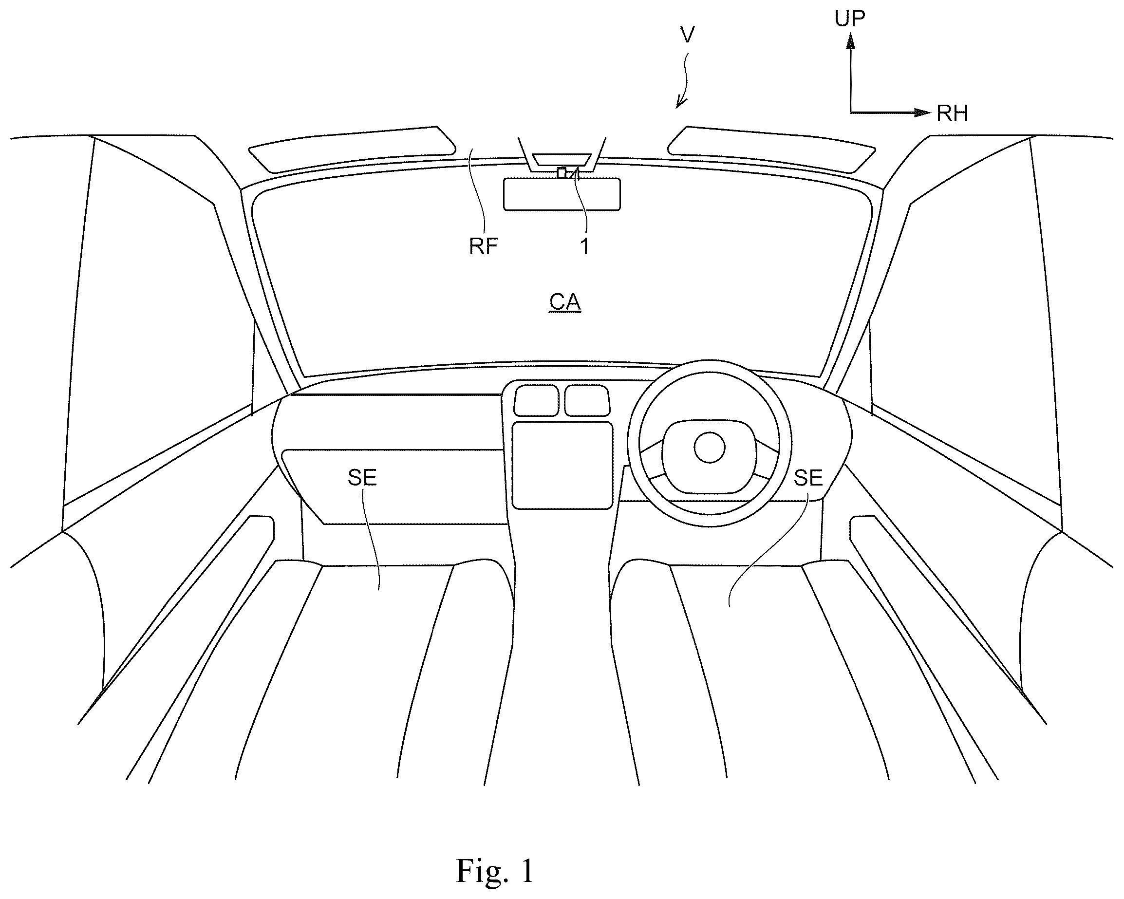
is a rear view from a rear of a vehicle illustrating a vehicle cabin to which a vehicle cabin illumination device according to the present embodiment is applied. is a bottom view of the vehicle cabin illumination device illustrated in , viewed from below the vehicle. is an oblique view of the vehicle cabin illumination device illustrated in , viewed from a right oblique rear side of the vehicle. is an exploded view of the vehicle cabin illumination device illustrated in with a lower case and a panel removed. is an exploded view of the panel illustrated in removed from the lower case. is the bottom view from below the vehicle illustrating a positioning of a first lens, a second lens, and a substrate illustrated in . is a cross-sectional view from the rear of the vehicle illustrating an inside of the vehicle cabin illumination device illustrated in ( 7 - 7 line cross-sectional view of ). is the cross-sectional view from a right side of the vehicle illustrating the inside of the vehicle cabin illumination device illustrated in ( 8 - 8 line cross-sectional view of ). is the cross-sectional view from the right side of the vehicle illustrating the inside of the vehicle cabin illumination device illustrated in ( 9 - 9 line cross-sectional view of ). A is the bottom view schematically illustrating a decorative illuminator in a down illumination state of the vehicle cabin illumination device. B is the bottom view schematically illustrating the decorative illuminator in a spot illumination state of the vehicle cabin illumination device. C is the bottom view schematically illustrating the decorative illuminator in a room illumination state of the vehicle cabin illumination device.
DESCRIPTION OF EMBODIMENT
Hereinafter, a vehicle cabin illumination device 1 according to the present embodiment will be described with reference to the drawings. As illustrated in , the vehicle cabin illumination device 1 is configured as a device for illuminating an inside of a vehicle cabin CA in a vehicle (automobile) V. The arrows UP, FR, and RH illustrated in the drawings as appropriate indicate upper side of the vehicle, front side of the vehicle, and right side of the vehicle (one side of vehicle width direction), respectively. In a following description, when directions up-down, front-back, and left-right are used, they refer to vehicle up and down direction, vehicle front and back directions, and vehicle left and right directions unless otherwise noted. As illustrated in to , the vehicle cabin illumination device 1 as a whole is formed in a substantially rectangular flat shape with the up-down direction as thickness direction and the left-right direction as longitudinal direction. The vehicle cabin illumination device 1 is provided in a center in the lift-right direction on a front-end portion of a ceiling RF of the vehicle cabin CA (see ), and a panel 30 described further below is exposed from the ceiling RF to a vehicle cabin CA side. The vehicle cabin illumination device 1 comprises a frame 10 , a case 20 , a substrate 50 , a first lens 60 , and a second lens 70 . Each of the components of the vehicle cabin illumination device 1 will be described below. Frame 10 As illustrated in and to , the frame 10 constitutes a framework of the vehicle cabin illumination device 1 , and is formed in a substantially rectangular shape with the left-right direction as the longitudinal direction when viewed from below (from inside of the vehicle cabin CA). Fixing claws 10 A are provided at both ends of the frame 10 in the left-right direction, and the vehicle cabin illumination device 1 is fixed to the ceiling RF by engaging the fixing claws 10 A to the ceiling RF of the vehicle cabin CA. At a rear of the frame 10 is a lens housing 10 B housing the first lens 60 and the second lens 70 described further below. The lens housing 10 B is formed in a substantially U-shaped cylindrical shape, which is open to the front side when viewed from below. In a middle of the frame 10 in the front-back direction, a left and right pair of first cylinders 10 C (see ) are formed at outer ends in the left-right direction, and the first cylinder 10 C is formed in a substantially rectangular cylindrical shape with the up-down direction as axis direction. An inner circumference surface of a lower portion of the first cylinder 10 C slopes inward toward an upper side, and a step protruding inward of the first cylinder 10 C is formed at a boundary between upper and lower portions of the first cylinder 10 C. An inclination angle of an outer side surface in the left-right direction on the inner circumference surface of the lower portion of the first cylinder section 10 C is set larger than the inclination angles of the other surfaces. In the middle of the frame 10 in the front-back direction, a left and right pair of second cylinders 10 D are formed (see ). The second cylinder 10 D is disposed an inner side in the left-right direction of the first cylinder 10 C, and is formed in a substantially bottom rectangular cylinder open to the upper side. A rectangular translucent hole 10 E is formed through a lower wall of the second cylinder 10 D. The first cylinder 10 C and the second cylinder 10 D are disposed on the front side of the outer ends of the lens housing 10 B in the left-right direction, and the first cylinder 10 C and the second cylinder 10 D are made to communicate with the lens housing 10 B. As illustrated in , a center light guide lens 11 is provided in the center of the frame 10 in the left-right direction, in the middle of the front-back direction. The center light guide lens 11 is formed in a substantially rectangular plate with the up-down direction as the thickness direction and the front-back direction as the longitudinal direction, and the front end of the center light guide lens 11 is bent to the upper side. In the middle of the frame 10 in the front-back direction, a front and back pair of side light guide lenses 12 are provided outside the center light guide lens 11 in the left-right direction, respectively. In other words, the frame 10 is provided with four side light guide lenses 12 . The side light guide lenses 12 are formed in a substantially rectangular block. The center light guide lens 11 and the side light guide lenses 12 are formed of a material that can transmit light. The front end of the frame 10 is provided with an indicator lens group 13 . The indicator lens group 13 is comprised of a plurality of indicator light guide lenses 14 , and the indicator light guide lenses 14 are formed of the material that can transmit the light. Case 20 As illustrated in through , the case 20 constitutes an outer contour of the vehicle cabin illumination device 1 . The case 20 has a case body 21 and a panel 30 . The case body 21 is described below, and the panel 30 is described further below. The case body 21 is comprised of case components divided into two parts, upper and lower. Specifically, the case body 21 comprises an upper case member 22 that constitutes the upper portion of the case body 21 and a lower case member 23 that constitutes the lower portion of the case 20 . The upper case member 22 is formed in a substantially rectangular box open downwardly, and is assembled to an outer circumference of the frame 10 by means of a claw fit, covering the frame 10 from the upper side. A sensor housing 22 A is formed at the rear of the upper case member 22 , which rises downward. The sensor housing 22 A is formed in a shape corresponding to the lens housing 10 B of the frame 10 when viewed from below, and is formed in a concave shape open to the upper side and fitted into the lens housing 10 B. A radio wave sensor 40 (see , , and ) is housed in the center of the sensor housing 22 A in the left-right direction. The radio wave sensor 40 is a sensor using radio waves such as ultrasonic, millimeter wave, infrared, and visible light, and is electrically connected to a controller 51 described further below. The radio wave sensor 40 is configured as the sensor for detecting an occupant's entry into the vehicle cabin CA. Specifically, the radio wave sensor 40 has a transmitter and a receiver. The transmitter transmits the radio wave toward the inside of the vehicle cabin CA, and the receiver receives a reflected wave of the radio wave transmitted from the transmitter. The controller 51 then determines, based on a waveform of the reflected wave, whether the occupant is boarding inside the vehicle cabin CA. The radio wave sensor 40 can be used, for example, in an anti-theft device for detecting unauthorized entry into the vehicle cabin, and in a left behind detection device for detecting a child left behind in the vehicle cabin, and in other devices having various functions installed in the vehicle. The lower case member 23 is formed in the substantially rectangular box with a relatively shallow bottom that is open to the upper side, and is assembled to the outer circumference of the frame 10 by means of the claw fit, covering the frame 10 from below. The lower case member 23 is comprised of a light-impermeable resin material. The lower case member 23 is provided with a case-side first translucent portion 23 A at a position corresponding to the lens housing 10 B of the frame 10 , and the case-side first translucent portion 23 A is formed in the shape corresponding to the lens housing 10 B viewed from below. The lower case member 23 has a case-side depression 23 B below the center light guide lens 11 of the frame 10 . The case-side depression 23 B is formed in the concave shape that is raised to the upper side and open downwardly, and extends in the front-back direction. A case-side second translucent portion 23 C is provided in the case-side depression 23 B, and the case-side second translucent portion 23 C is formed in the substantially rectangular shape with the front-back direction as the longitudinal direction. The lower case member 23 has case-side third translucent portions 23 D at the positions corresponding to the side light guide lenses 12 of the frame 10 , and the case-side third translucent portions 23 D are formed in the substantially rectangular shape viewed from below. The lower case member 23 has case-side fourth translucent portions 23 E at the positions corresponding to the indicator light guide lenses 14 of the frame 10 . The case-side fourth translucent portions 23 E are formed in shapes corresponding to the indicator light guide lenses 14 viewed from below. The case-side first translucent portion 23 A, the case-side second translucent portion 23 C, the case-side third translucent portions 23 D, and the case-side fourth translucent portions 23 E are formed of a resin material that can transmit light, and these translucent portions and the lower case member 23 are formed as one piece by a two-color molding or other method. A case-side ridge 23 F raised downwardly is formed at the front-end of the lower case member 23 , and the case-side ridge 23 F is extended in the left-right direction. The case-side ridge 23 F is formed in a substantially V-shape open to the upper side when viewed from the left-right direction, and the case-side fourth translucent portions 23 E described above is formed on a rear wall and a lower end of the case-side ridge 23 F. In the middle of the lower case member 23 in the front-back direction, on outer portions in the left-right direction, a left and right pair of case-side openings 23 G are formed through. The case-side openings 23 G are formed in the substantially rectangular shape with the left-right direction as the longitudinal direction. A size of the case-side openings 23 G is set so that the first cylinder 10 C and the second cylinder 10 D of the frame 10 are positioned inside the case-side openings 23 G when viewed from below. Substrate 50 As illustrated in and to , the substrate 50 is formed as the substantially rectangular plate with the up-down direction as the thickness direction and the left-right direction as the longitudinal direction. The substrate 50 is disposed on the upper side of the front portion of the frame 10 , sandwiched in the up-down direction between the frame 10 and the upper case member 22 , and fastened to the frame 10 together with the upper case member 22 by a screw SC (see ). Specifically, the substrate 50 is disposed on the front side of the lens housing 10 B. This setting ensures that the radio wave sensor 40 and the substrate 50 do not overlap when viewed from below. The controller 51 (see ) is provided on a top surface of the substrate 50 . A connector 52 is provided at a right end of the top surface of the substrate 50 , and the connector 52 is electrically connected to the controller 51 . A vehicle-side connector (not illustrated) is plugged into the connector 52 to supply power to the substrate 50 . At a rear end of a lower surface of the substrate 50 , first cabin LEDs 53 as a left and right pair of first light sources are provided at the outer end in the left-right direction. The first cabin LEDs 53 are positioned in the first cylinder 10 C of the frame 10 when viewed from below (see ), and irradiates light downward. At the rear end of the lower surface of the substrate 50 , second cabin LEDs 54 as a left and right pair of second light sources are provided respectively. The second cabin LEDs 54 are positioned opposite the translucent hole 10 E in the second cylinder 10 D in the frame 10 , viewed from below (see ), and irradiates light downward. On the lower surface of the substrate 50 , a left and right pair of center button LEDs 55 are provided. The center button LEDs 55 are positioned on the upper side of the front-end of the center light guide lens 11 . The center button LEDs 55 irradiate light downward, and light entering the front-end of the center light guide lens 11 is guided backward in the center light guide lens 11 . On the lower surface of the substrate 50 , side button LEDs 56 are provided on the upper side of the side light guide lens 12 , respectively. The side button LEDs 56 irradiate light downward, and light is transmitted through the side light guide lens 12 and guided to the lower surface of the side light guide lens 12 . On the lower surface of the substrate 50 , a plurality of indicator LEDs 57 are provided on the upper side of the indicator light guide lens 14 . The indicator LEDs 57 irradiate light downward, and light is transmitted through the indicator light guide lens 14 and guided to the lower surface of the indicator light guide lens 14 . These LEDs are electrically connected to the controller 51 and are lit or unlit by the controller 51 . Panel 30 As illustrated in , , and to , the panel 30 is formed in a substantially rectangular sheet shape with the up-down direction as the thickness direction and the left-right direction as the longitudinal direction. The panel 30 is formed integrally with the lower case member 23 so as to cover the lower surface and side surface of the lower case member 23 . In other words, a panel-side ridge 30 A corresponding to the case-side ridge 23 F of the lower case member 23 is formed at the front-end of the panel 30 . The panel-side ridge 30 A is formed in the substantially V-shape, open to the upper side, when viewed from the left-right direction. A panel-side depression 30 B corresponding to the case-side depression 23 B of the lower case member 23 is formed in the center of the panel 30 in the left-right direction. The panel-side depression 30 B is formed in the concave shape that is raised to the upper side and open downwardly, and extends in the front-back direction. The panel 30 is formed of the material that can transmit light, and the top surface of the panel 30 is painted for light shielding. This makes the panel 30 impenetrable to light. At the rear of the panel 30 , a decorative illuminator 30 C is provided at the position opposite to the case-side first translucent portion 23 A of the lower case member 23 , and the decorative illuminator 30 C is formed to correspond to the case-side first translucent portion 23 A when viewed from below. In other words, the decorative illuminator 30 C extends in the left-right direction, is disposed below the radio wave sensor 40 , and covers the radio wave sensor 40 from below. The decorative illuminator 30 C has a plurality of decorative translucent portions 30 D as translucent portions, and a predetermined pattern is formed in the decorative illuminator 30 C by the plurality of decorative translucent portions 30 D. Specifically, the decorative translucent portion 30 D is not painted for light shielding, and the decorative illuminator 30 C is illuminated in the predetermined pattern when light irradiated from the first lens 60 and the second lens 70 (described further below) passes through the decorative translucent portion 30 D. In the drawings, only specific decorative translucent portion 30 D is labeled with a reference symbol for the sake of convenience. The outer portion of the decorative illuminator 30 C in the left-right direction is a first decorative illuminator 30 C 1 , and the middle of the decorative illuminator 30 C in the left-right direction is a second decorative illuminator 30 C 2 . The first decorative illuminator 30 C 1 and the second decorative illuminator 30 C 2 are aligned continuously in the left-right direction (see ). The portion positioned below the case-side second translucent portion 23 C of the lower case member 23 in the panel-side depression 30 B of the panel 30 is a center touch button 30 E. The center touch button 30 E is configured as an operator for operating a sunroof (not illustrated) provided on the ceiling RF. The portions positioned below the case-side third translucent portion 23 D of the lower case member 23 in the panel 30 are the side touch buttons 30 F 1 to 30 F 4 . The side touch buttons 30 F 1 to 30 F 4 are configured as the operators used to lit or unlit the first cabin LED 53 and the second cabin LED 54 . The center touch button 30 E and side touch buttons 30 F 1 to 30 F 4 are formed with a display (not illustrated), which has letters, figures, symbols, marks, and so on. The display is configured in the same manner as the decorative translucent portions 30 D. In other words, the display is not painted for light shielding, and the display is illuminated by light irradiated downward from the case-side second translucent portion 23 C and the case-side third translucent portion 23 D which passes through the display. On the upper side of the lower case member 23 , detection electrodes (not illustrated) are disposed at the positions corresponding to the center touch button 30 E and the side touch buttons 30 F 1 to 30 F 4 , respectively. Each detection electrode is connected to the substrate 50 and electrically connected to the controller 51 . The detection electrodes detect the contact (proximity) of the occupant's fingers with the center touch button 30 E and the side touch buttons 30 F 1 to 30 F 4 . Specifically, when the occupant's finger contacts the center touch button 30 E (side touch buttons 30 F 1 to 30 F 4 ), a capacitance between the detection electrode and the occupant's finger increases, and the controller 51 detects the occupant's finger contacting the center touch button 30 E (side touch buttons 30 F 1 to 30 F 4 ) based on an output from the detection electrode. Thereby, the center touch button 30 E and the detection electrode constitute a touch switch, and the side touch buttons 30 F 1 to 30 F 4 and the detection electrode constitute the touch switch. The portion positioned below the case-side fourth translucent portion 23 E of the lower case member 23 in the panel 30 is an indicator 30 G. The indicator 30 G has the display (not illustrated), which has letters, figures, symbols, marks, and so on. This display is configured in the same manner as the center touch button 30 E and the side touch buttons 30 F 1 to 30 F 4 . In other words, the display is not painted for light shielding, and the display in the indicator 30 G is illuminated by light irradiated downward from the case-side fourth translucent portion 23 E, which passes through the display. An opening cover 30 H is formed at the position corresponding to the case-side opening 23 G of the lower case member 23 in the panel 30 . (see ) The opening cover 30 H is formed in a frame shape viewed from below to cover the inner circumference surface of the case-side opening 23 G, and is formed in a substantially crank shape viewed from circumferential direction of the case-side opening 23 G. As a result, a panel side opening 30 J formed by the opening cover 30 H is formed through the panel 30 in the up-down direction, so that the first cylinder 10 C and the second cylinder 10 D of the frame 10 are positioned within the panel side opening 30 J viewed from below. A pair of left and right cabin illuminators 32 are provided within the opening cover 30 H of the panel 30 . The cabin illuminators 32 are formed in the substantially rectangular sheet shape with the up-down direction as the thickness direction, and are made of the material that can transmit light. The cabin illuminators 32 are disposed adjacent below the first cylinder 10 C and the second cylinder 10 D of the frame 10 . First Lens 60 As illustrated in and to , the first lens 60 is comprised of the material that can transmit light. The first lens 60 has a first lens body 60 A, and the first lens body 60 A is formed in a substantially long plate shape with the up-down direction as the thickness direction and extending in the left-right direction. Specifically, the first lens body 60 A is formed in the substantially U-shape open to the front side viewed from below to fill up the lens housing 10 B of the frame 10 , and is housed within the lens housing 10 B. A connector 60 B is formed at the front-ends of both ends of the first lens 60 in the left-right direction, and the connector 60 B is bent to the upper oblique forward side. A lens base 60 C is provided on the front side of both ends of the first lens body 60 A in the left-right direction, respectively. The lens base 60 C is formed in the shape of a substantially bottomed rectangular cylinder open to the upper side and is disposed in the upper portion of the first cylinder 10 C of the frame 10 . The lens base 60 C is disposed on the upper side than the first lens body 60 A, and the connector 60 B of the first lens body 60 A is connected to the lower end of the lens base 60 C. The lens base 60 C is sandwiched top and bottom by the first cylinder 10 C and the substrate 50 , and the first cabin LED 53 is positioned within the opening of the lens base 60 C. Inside the lens base 60 C is a light-entering portion 60 D (see ). The light-entering portion 60 D is formed in a substantially square weight and projects upward from the lower wall of the lens base 60 C. A top surface of the light-entering portion 60 D is formed along a plane orthogonal to the up-down direction. The top surface of the light-entering portion 60 D has a concave 60 E (see ) open to the upper side, and the inner circumference surface of the concave 60 E slopes inwardly toward below. The first cabin LED 53 is positioned in the concave 60 E, when viewed from below. A convex curved surface 60 F (see ) is formed on the bottom surface of the concave 60 E, and the convex curved surface 60 F is disposed in a position outside of the first cabin LED 53 in the left-right direction when viewed from the rear side. The convex curved surface 60 F is formed in a substantially arc shape that is convex toward the first cabin LED 53 when viewed from the rear side. As a result, light irradiated downwardly from the first cabin LED 53 is guided outwardly in the left-right direction by the light-entering portion 60 D and transmitted through the cabin illuminator 32 of the panel 30 to mainly illuminate the vehicle seat SE (see ) of the vehicle V, which is positioned outside the vehicle cabin illumination device 1 in the left-right direction. When the first cabin LED 53 is lit, light entering the light-entering portion 60 D is guided to the first lens body 60 A by the connector 60 B, and light guided to the first lens body 60 A mainly illuminates the first decorative illuminator 30 C 1 of the decorative illuminator 30 C in the panel 30 from the upper side. In other words, light from the first lens body 60 A illuminates the decorative translucent portion 30 D of the first decorative illuminator 30 C 1 , so that the first decorative illuminator 30 C 1 is illuminated in the predetermined pattern. Second Lens 70 The second lens 70 , like the first lens 60 , is comprised of the material that can transmit light. The second lens 70 has a second lens body 70 A, and the second lens body 70 A is formed in the substantially long plate shape with the up-down direction as the thickness direction and extending in the left-right direction. Specifically, the second lens body 70 A, like the first lens body 60 A, is formed in the substantially U-shape open to the front side when viewed from below so as to fill up the lens housing 10 B of the frame 10 , and is housed in the lens housing 10 B on the lower side of the first lens body 60 A. The second lens 70 has a second lens light guide 70 B, and the second lens light guide 70 B is formed as a substantially long round bar and bent into the substantially U-shape that is open to the front side when viewed from below. The rear end of the middle of the second lens 70 in the left-right direction is bent upward and connected to the middle of the second lens light guide 70 B in the longitudinal direction. The longitudinal ends of the second lens light guide 70 B are light-entering portions 70 C. The light-entering portions 70 C are bent upward and disposed in the second cylinder 10 D of the frame 10 . The end surfaces of the light-entering portions 70 C are formed along a plane perpendicular to the up-down direction and are positioned below the second cabin LED 54 . As a result, light irradiated downwardly from the second cabin LED 54 passes through the light-entering portion 70 C and the translucent hole 10 E of the frame 10 and through the cabin illuminator 32 of the panel 30 to illuminate below the vehicle cabin illumination device 1 in the vehicle compartment CA. When the second cabin LED 54 is lit, light entering the light-entering portion 70 C is guided to the second lens body 70 A by the second lens light-guide 70 B, and light guided to the second lens body 70 A mainly illuminates the second decorative illuminator 30 C 2 of the decorative illuminator 30 C in the panel 30 from the upper side. In other words, light from the second lens body 70 A illuminates the decorative translucent portion 30 D of the second decorative illuminator 30 C 2 , so that the second decorative illuminator 30 C 2 is illuminated in the predetermined pattern. As described further below in detail, the above-mentioned controller 51 controls the first cabin LED 53 and the second cabin LED 54 to turn on and off and controls the brightness of light of the first cabin LED 53 and the second cabin LED 54 when lit to change an illumination form of the decorative illuminator 30 C. The controller 51 is electrically connected to an ECU (Electronic Control Unit: not illustrated), which detects and stores information such as a locking and unlocking status of vehicle doors and a vehicle speed. The controller 51 is also electrically connected to an illuminance sensor (not illustrated), which is disposed in the vehicle cabin and can detect the brightness in the cabin. The above-mentioned side touch buttons 30 F 1 and 30 F 2 are used as operators for illuminating areas around the left and right vehicle seats SE respectively by the vehicle cabin illumination device 1 The side touch button 30 F 3 is used as the operator for illuminating the entire front area in the vehicle cabin CA by the vehicle cabin illumination device 1 . Furthermore, the side touch button 30 F 4 is configured as the operator for switching an interlocking or non-interlocking of the vehicle cabin illumination device 1 with the opening/closing operation of the door (not illustrated) of the vehicle V. Effects Next, the actions and effects of the present embodiment will be described while describing the operation of the vehicle cabin illumination device 1 . In a non-operating state of the vehicle cabin illumination device 1 , the first cabin LED 53 and second cabin LED 54 are unlit. When the controller 51 detects that the vehicle is in use and that the illuminance in the vehicle cabin is below a predetermined value, the controller 51 lights a left and right pair of the second cabin LEDs 54 . Thus, light from the second cabin LED 54 illuminates the cabin illuminator 32 of the panel 30 and the decorative translucent portion 30 D of the second decorative illuminator 30 C 2 in the decorative illuminator 30 C. As a result, the decorative illuminator 30 C is decorated with the predetermined pattern in the portion of the second decorative illuminator 30 C 2 . In this case, as illustrated in A , the brightness of light irradiated from the second cabin LED 54 is controlled by the controller 51 so that a luminance of the decorative translucent portion 30 D in the second decorative illuminator 30 C 2 is relatively low to prevent eyesores during driving (this state is hereinafter referred to as a “down illumination state”). In other words, when the vehicle is in use and the brightness in the vehicle cabin is below the predetermined value, the second cabin LED 54 is always lit and the vehicle cabin illumination device 1 is in the down illumination state. In the down illumination state, a lower space of the vehicle cabin illumination device 1 is illuminated with reduced luminance by light transmitted from the second cabin LED 54 through the cabin illuminator 32 of the panel 30 . In A , the decorative illuminator 30 C is hatched, the decorative translucent portion 30 D of the first decorative illuminator 30 C 1 is painted over with black, and the decorative translucent portion 30 D of the second decorative illuminator 30 C 2 is painted over with gray. When the occupant touches the side touch button 30 F 1 (side touch button 30 F 2 ) in the down illumination state of the vehicle cabin illumination device 1 , the first cabin LED 53 on the left side (right side) is lit by the controller 51 while the second cabin LED 54 remains lit. As a result, light from the first cabin LED 53 illuminates the cabin illuminator 32 on the left side (right side) of the panel 30 and the decorative translucent portion 30 D of the first decorative illuminator 30 C 1 on the left side (right side) in the decorative illuminator 30 C. In this case, as illustrated in B , the brightness of light irradiated from the second cabin LED 54 is the same as in the down illumination state, and the luminance of the decorative translucent portion 30 D of the second decorative illuminator 30 C 2 is the same as in the down illumination state. The brightness of light irradiated from the first cabin LED 53 is controlled by the controller 51 so that the luminance of the decorative translucent portion 30 D of the first decorative illuminator 30 C 1 is higher than that of the decorative translucent portion 30 D of the second decorative illuminator 30 C 2 (this state is hereinafter called a “spot illumination state”). As a result, in the spot illumination state of the vehicle cabin illumination device 1 , mainly the area around the vehicle seat SE is illuminated by the vehicle cabin illumination device 1 , and the illumination form of the decorative illuminator 30 C is changed so that the luminance of the first decorative illuminator 30 C 1 is higher than that of the second decorative illuminator 30 C 2 . In B , the state in which both left and right first cabin LEDs 53 are lit is illustrated. Furthermore, in B , the decorative illuminator 30 C is hatched and the decorative translucent portion 30 D of the first decorative illuminator 30 C 1 is painted over with gray lighter than the decorative translucent portion 30 D of the second decorative illuminator 30 C 2 . When the occupant touches the side touch button 30 F 1 (side touch button 30 F 2 ) again, the controller 51 turns off the left side (right side) first cabin LED 53 and the vehicle cabin illumination device 1 returns to the down illumination state. When the occupant touches the side touch button 30 F 3 in the down illumination state of the vehicle cabin illumination device 1 , the controller 51 causes light of the second cabin LED 54 to be bright and the first cabin LEDs 53 on both the left and right sides to be lit. When touching the side touch button 30 F 3 , as illustrated in C , the brightness of light irradiated from the first cabin LED 53 is the same as in the spot illumination state, and the luminance of the decorative translucent portion 30 D of the first decorative illuminator 30 C 1 is the same as in the spot illumination state. Furthermore, the brightness of light irradiated from the second cabin LED 54 is controlled by the controller 51 so that the luminance of the decorative translucent portion 30 D of the second decorative illuminator 30 C 2 is higher than that of the decorative translucent portion 30 D of the first decorative illuminator 30 C 1 (this state is hereinafter referred to as a “room illumination state”). As a result, in the room illumination state of the vehicle cabin illumination device 1 , the entire front part in the vehicle cabin CA is illuminated by the vehicle cabin illumination device 1 , and the illumination form of the decorative illuminator 30 C is changed so that the luminance of the decorative translucent portion 30 D of the second decorative illuminator 30 C 2 is higher than that of the decorative translucent portion 30 D of the first decorative illuminator 30 C 1 . In C , the decorative illuminator 30 C is hatched and the second decorative illuminator 30 C 2 is painted over with white. When the occupant touches the side touch button 30 F 3 again, the left and right first cabin LEDs 53 are turned off and the brightness of light irradiated from the second cabin LED 54 is controlled to be the same brightness as in the down illumination state by the controller 51 . As a result, the vehicle cabin illumination device 1 returns to the down illumination state. As described above, in the vehicle cabin illumination device 1 , the first cabin LED 53 and the second cabin LED 54 are housed in the case 20 . The panel 30 of the case 20 is provided with the cabin illuminator 32 , and light irradiated downward from the first cabin LED 53 and the second cabin LED 54 is transmitted through the cabin illuminator 32 to illuminate the vehicle cabin CA. Here, the panel 30 is provided with the decorative illuminator 30 C having the decorative translucent portion 30 D through which light can be transmitted. The first lens 60 and the second lens 70 are housed in the case 20 , and light irradiated from the first cabin LED 53 is guided to a back side (upper side) of the decorative illuminator 30 C by the first lens 60 , and light irradiated from the second cabin LED 54 is guided to the back side of the decorative illuminator 30 C by the second lens 70 . As a result, the first cabin LED 53 and the second cabin LED 54 for illuminating inside the vehicle cabin CA can be used to illuminate the decorative illuminator 30 C to decorate the vehicle cabin illumination device 1 . In other words, the decorative illuminator 30 C can be illuminated without installing a separate light source to illuminate the decorative illuminator 30 C. Therefore, the design of the vehicle cabin illumination device 1 can be improved while controlling cost increase. As described above, light irradiated from the first cabin LED 53 is guided to the back side of the decorative illuminator 30 C by the first lens 60 , and light irradiated from the second cabin LED 54 is guided to the back side of the decorative illuminator 30 C by the second lens 70 . Therefore, by setting the size and shape of the first lens 60 and the second lens 70 appropriately in response to the size and shape of the decorative illuminator 30 C, the decorative illuminator 30 C can be easily illuminated. The radio wave sensor 40 is housed in the sensor housing 22 A of the upper case member 22 , and the decorative illuminator 30 C of the panel 30 is positioned below the radio wave sensor 40 , covering the radio wave sensor 40 from below. This allows the decorative illuminator 30 C of the panel 30 to be provided on the panel 30 by utilizing a portion of the panel 30 that covers the radio wave sensor 40 . The decorative illuminator 30 C has the first decorative illuminator 30 C 1 that is illuminated by light from the first lens body 60 A of the first lens 60 and the second decorative illuminator 30 C 2 that is illuminated by light from the second lens body 70 A of the second lens 70 . The decorative illuminator 30 C is extended in the vehicle width direction when viewed from below, and the first decorative illuminator 30 C 1 and the second decorative illuminator 30 C 2 are arranged side by side in the longitudinal direction of the decorative illuminator 30 C. Therefore, the occupant can easily recognize a lit/unlit status of the first cabin LED 53 and the second cabin LED 54 . Thus, the convenience for the occupant can be improved. The first decorative illuminator 30 C 1 and the second decorative illuminator 30 C 2 are aligned continuously in the longitudinal direction of the panel 30 . Therefore, for example, when the vehicle cabin illumination device 1 is in the room illumination state, the entire decorative illuminator 30 C is illuminated, thus enabling a powerful decoration to be realized in the decorative illuminator 30 C. The controller 51 also controls the brightness of light of the first cabin LED 53 and the second cabin LED 54 when they are lit to change the illumination form of the decorative illuminator 30 C. Specifically, as described above, during the down illumination state, only the second cabin LED 54 is lit and only the second decorative illuminator 30 C 2 is lit. During the spot illumination state, the first cabin LED 53 and the second cabin LED 54 are lit so that the luminance of the second decorative illuminator 30 C 2 is the same as during the down illumination state and the luminance of the first decorative illuminator 30 C 1 is higher than that of the second decorative illuminator 30 C 2 . Furthermore, in the room illumination state, the first cabin LED 53 and the second cabin LED 54 are lit so that the luminance of the first decorative illuminator 30 C 1 is the same as in the spot illumination state and the luminance of the second decorative illuminator 30 C 2 is higher than that of the first decorative illuminator 30 C 1 . This allows for more variations in the illumination form of the decorative illuminator 30 C and also makes it easier for the occupant to recognize the illumination state of the vehicle cabin illumination device 1 . Therefore, the design of the vehicle cabin illumination device 1 can be effectively improved and the convenience for the occupant can be further enhanced. The substrate 50 is disposed in the position where it does not overlap with the radio wave sensor 40 when viewed from below, and the first lens 60 and the second lens 70 are disposed between the radio wave sensor 40 and the decorative illuminator 30 C. This prevents the radio waves transmitted from the radio wave sensor 40 to the vehicle cabin CA side from being blocked by the substrate 50 , and prevents light of the first cabin LED 53 and the second cabin LED 54 provided on the substrate 50 from being blocked by the radio wave sensor 40 , while allowing the first lens 60 and the second lens 70 to guide light of the first cabin LED 53 and the second cabin LED 54 to the back side of the decorative illuminator 30 C. EXPLANATION OF THE REFERENCE NUMERALS 1 : Vehicle cabin illumination device 20 : Case 30 C: Decorative illuminator 30 C 1 : First decorative illuminator 30 C 2 : Second decorative illuminator 32 : Cabin illuminator 40 : Radio wave sensor 50 : Substrate 51 : Controller 53 : First cabin LED (first light source) 54 : Second cabin LED (second light source) 60 : First lens 70 : Second lens CA: Vehicle cabin
Figures (10)
Citations
This patent cites (12)
- US4617617
- US7287886
- US10106078
- US11479167
- US2006/0187659
- US2008/0049435
- US2009/0251912
- US2009/0316421
- US2022/0203890
- US2008-201221
- US20120088126
- USWO-2008044460