Abstract
To improve workability when attaching an airbag module disposed in a side portion of a vehicle seat from a seat back side. A vehicle seat (S) includes: a side frame ( 13 ) which constitutes a side portion of a seat back frame ( 10 ); a bracket ( 20 ) which includes an attachment portion ( 21 ) attached to a side surface of the side frame ( 13 ) on a seat inner side and a back protrusion portion ( 22 ) protruding backward from the attachment portion ( 21 ); and an airbag module ( 30 ) which includes a retainer ( 34 ) fixed to the back protrusion portion ( 22 ).
Claims (12)
1 . A vehicle seat comprising: a plate frame member which constitutes a side portion of a seat back frame; a bracket which is attached to the seat back frame; and an airbag module which is fixed to the bracket, wherein the seat back frame includes an upper frame that is connected to an upper end portion of the plate frame member, wherein the bracket is positioned on an opposite side of the plate frame member in a seat width direction with respect to the upper frame, wherein the bracket includes an outer extension portion that extends outward in the seat width direction, and wherein the outer extension portion covers a connection portion between the bracket and the upper frame from a rear.
12 . A vehicle seat comprising: a plate frame member which constitutes a side portion of a seat back frame; a bracket which is attached to the seat back frame; and an airbag module which is fixed to the bracket, wherein the seat back frame includes a lower frame that is connected to a lower end portion of the plate frame member, wherein the airbag module includes an airbag and an inflator configured to generate gas to expand and deploy the airbag, and wherein the inflator is provided in the lower frame, wherein the lower frame includes a front wall, wherein the front wall covers the inflator from a front, and wherein an outer end of the front wall is located on an inner side of an inner end of the bracket in the seat width direction.
Show 10 dependent claims
2 . The vehicle seat according to claim 1 , wherein an inner end of the bracket is located on an inner side of an inner end of the plate frame member in the seat width direction.
3 . The vehicle seat according to claim 1 , wherein an outer end of the bracket is located on an outer side of an inner end of the plate frame member in the seat width direction.
4 . The vehicle seat according to claim 3 , wherein the bracket includes a relief portion to prevent the inner end of the plate frame member from coming into contact with the bracket.
5 . The vehicle seat according to claim 4 , wherein the relief portion is a recessed portion recessed inward in the seat width direction.
6 . The vehicle seat according to claim 3 , wherein the outer end of the bracket is located on an inner side of an outer end of the seat back frame in the seat width direction.
7 . The vehicle seat according to claim 1 , wherein a portion of the plate frame member covers a connection portion between the bracket and the upper frame from a rear.
8 . The vehicle seat according to claim 1 , wherein the airbag module includes a retainer configured to attach the airbag module to the seat back frame, and wherein the retainer covers the bracket from a rear.
9 . The vehicle seat according to claim 8 , wherein an inner end of the retainer is located on an inner side of an inner end of the bracket in the seat width direction.
10 . The vehicle seat according to claim 1 , wherein the seat back frame includes a pressure receiving member configured to receive a load from an occupant of the vehicle seat, wherein the pressure receiving member includes a plane-shaped portion configured to receive the load from the occupant and a connecting member connected to the seat back frame, and wherein the connecting member is positioned away from the bracket.
11 . The vehicle seat according to claim 10 , wherein the airbag module includes a retainer configured to attach the airbag module to the seat back frame, and wherein the retainer is positioned away from the connecting member.
Full Description
Show full text →
CROSS-REFERENCE TO RELATED APPLICATIONS
This application is a continuation of U.S. patent application Ser. No. 18/326,118, filed on May 31, 2023, which, in turn, is a continuation of U.S. patent application Ser. No. 17/351,299 (now U.S. Pat. No. 11,702,024), filed on Jun. 18, 2021, which, in turn, is a continuation of U.S. patent application Ser. No. 16/344,835 (now U.S. Pat. No. 11,040,686), filed on Apr. 25, 2019, which, in turn, is a National Stage of Entry PCT Application Number PCT/JP2017/035150, filed on Sep. 28, 2017. Further, this application claims the benefit of priority from the Japanese Patent Application Number 2016-216090, filed on Nov. 4, 2016, Japanese Patent Application Number 2017-014369, filed on Jan. 30, 2017, and Japanese Patent Application Number 2017-029330, filed on Feb. 20, 2017, the entire contents of which are incorporated herein by reference.
TECHNICAL FIELD
The present invention relates to a vehicle seat having an airbag provided in a side portion.
BACKGROUND
ART A vehicle seat equipped with a side airbag device which expands and deploys an airbag provided in a side portion of a vehicle seat in the event of side collision and protects an occupant is known (for example, see Patent Literature 1 below). CITATION LIST Patent Literature PATENT LITERATURE 1: JP 5669567 B2
SUMMARY
OF INVENTION Technical Problem In the above-described related art, an airbag module is attached to a bracket which extends from a side frame toward a seat front side. For that reason, the workability when attaching the airbag module from a seat back side to the seat frame was low. The present invention has been made in view of the above-described problem and an object of the present invention is to provide a vehicle seat which improves workability when attaching an airbag module disposed in a side portion of a vehicle seat from a seat back side. Solution to Problem According to the vehicle seat of the present invention, the above-described problems are solved by including: a side frame which constitutes a side portion of a seat back frame; a bracket which includes an attachment portion attached to a side surface of a side frame on a seat inner side and a back protrusion portion protruding backward from the attachment portion; and an airbag module which is fixed to the back protrusion portion. According to the above-described vehicle seat, since the bracket for attaching the airbag module is attached to the inner surface of the side frame, it is possible to obtain a compact width of the attachment portion of the airbag module in the right and left direction. Further, since the airbag module is attached to a back side in relation to the attachment portion between the bracket and the side frame, it is possible to improve workability when assembling the airbag module from the seat back side to the bracket. Further, in the above-described vehicle seat, the side frame may include a cylindrical pipe frame and a plate-shaped plate frame attached to a lower portion of the pipe frame, and the airbag module may be attached to a side surface of the plate frame on a seat outer side. In this way, it is possible to attach the airbag module to both of the bracket and the side surface of the plate frame on the seat outer side. Accordingly, it is possible to strongly attach the airbag module to a seat cushion frame as compared with a case in which the airbag module is attached to any one of the bracket and the plate frame. Further, in the above-described vehicle seat, the bracket may be attached to a lower portion in relation to a joint portion between the pipe frame and the plate frame in the pipe frame. In this way, since the bracket is attached a portion below the joint portion between the pipe frame and the plate frame in the side frame, that is, a portion not overlapping the joint portion, it is possible to prevent improvement of rigidity of the side frame. Accordingly, it is possible to maintain appropriate shock absorption of the side frame even when the bracket is attached. Further, in the above-described vehicle seat, the back protrusion portion may include a back extension portion which extends backward from the attachment portion and an outer extension portion which extends from the back extension portion toward a seat outer side, and the airbag module may be attached to the outer extension portion. In this way, it is possible to set the direction of the attachment portion to the pipe frame and the direction of the attachment portion to the airbag module in the bracket to be different from each other. Accordingly, it is possible to improve attachment workability by preventing interference between attachment positions of the bracket and the pipe frame and between attachment positions of the bracket and the airbag module. Further, in the above-described vehicle seat, the airbag module may include an airbag, an inflator which supplies a gas to the airbag, a casing which covers the inflator and the airbag, and a retainer including a protrusion portion which protrudes from the casing, and the outer extension portion of the bracket and the protrusion portion of the retainer may be fixed. In this way, it is possible to fix the retainer protruding from the airbag module and the bracket. Accordingly, it is possible to improve workability when attaching the airbag module to the bracket. Further, in the above-described vehicle seat, the outer extension portion of the bracket and the protrusion portion of the retainer may be fixed by fastening a nut to a bolt penetrating both portions, and the protrusion portion of the retainer may be provided with an opening portion through which the bolt is inserted. In this way, it is possible to easily fix the retainer of the airbag module and the bracket by using the bolt and the nut. Accordingly, it is possible to easily perform an operation of attaching the airbag module to the bracket. Further, in the above-described vehicle seat, the protrusion portion of the retainer may include an inner extension portion which is provided on a back side of the side frame to extend toward the inner side of the seat, and the inner extension portion and the outer extension portion may be fixed. In this way, it is possible to easily fix the retainer of the airbag module and the bracket from the seat back side by using the bolt and the nut. Accordingly, it is possible to easily perform an operation of attaching the airbag module to the bracket. Further, in the above-described vehicle seat, an end portion of the bolt may face backward and the nut may be a cap nut which covers the end portion of the bolt. In this way, it is possible to easily perform an operation of fastening the nut to the bolt from the seat back side. Further, since the end portion of the bolt is covered by the cap nut, it is possible to prevent the seat inner portion from being damaged by the end portion of the bolt. Further, in the above-described vehicle seat, the opening portion of the retainer may be provided across an end portion on the inner side of the seat. In this way, it is possible to fit the opening portion provided in the retainer to the bolt from the seat outer side. Accordingly, it is possible to easily perform an operation of attaching the airbag module to the bracket. Further, the above-described vehicle seat may include a seat back pad which covers the seat back frame and the seat back pad may include a storage portion which is opened in the side portion toward a seat outer side and stores the airbag module. In this way, it is possible to attach the airbag module by disposing the air bag module in the storage portion of the seat back pad even after the seat back pad is attached to the seat back frame. In this way, since it is possible to attach the airbag module after the seat back pad is attached to the seat back frame, no displacement of the airbag module occurs when attaching the seat back pad. Accordingly, it is possible to improve the arrangement accuracy of the airbag module. Advantageous Effects of Invention According to the present invention, it is possible to improve the workability when attaching the airbag module disposed in the side portion of the vehicle seat from the seat back side. According to an aspect of the present invention, it is possible to strongly attach the airbag module to the seat cushion frame. According to an aspect of the present invention, it is possible to maintain appropriate shock absorption of the side frame even when the bracket is attached. According to an aspect of the present invention, it is possible to improve attachment workability by preventing an interference between attachment positions of the bracket and the pipe frame and between attachment positions of the bracket and the airbag module. According to an aspect of the present invention, it is possible to improve workability when attaching the airbag module to the bracket. According to an aspect of the present invention, it is possible to easily fix the retainer of the airbag module and the bracket by using a bolt and a nut. According to an aspect of the present invention, it is possible to easily fix the retainer of the airbag module and the bracket from the seat back side by using a bolt and a nut. According to an aspect of the present invention, it is possible to prevent the seat inner portion from being damaged by the end portion of the bolt. According to an aspect of the present invention, it is possible to fit the opening portion provided in the retainer to the bolt from the seat outer side. According to an aspect of the present invention, it is possible to attach the airbag module by disposing the airbag module in the storage portion of the seat back pad even after the seat back pad is attached to the seat back frame.
BRIEF DESCRIPTION OF DRAWINGS
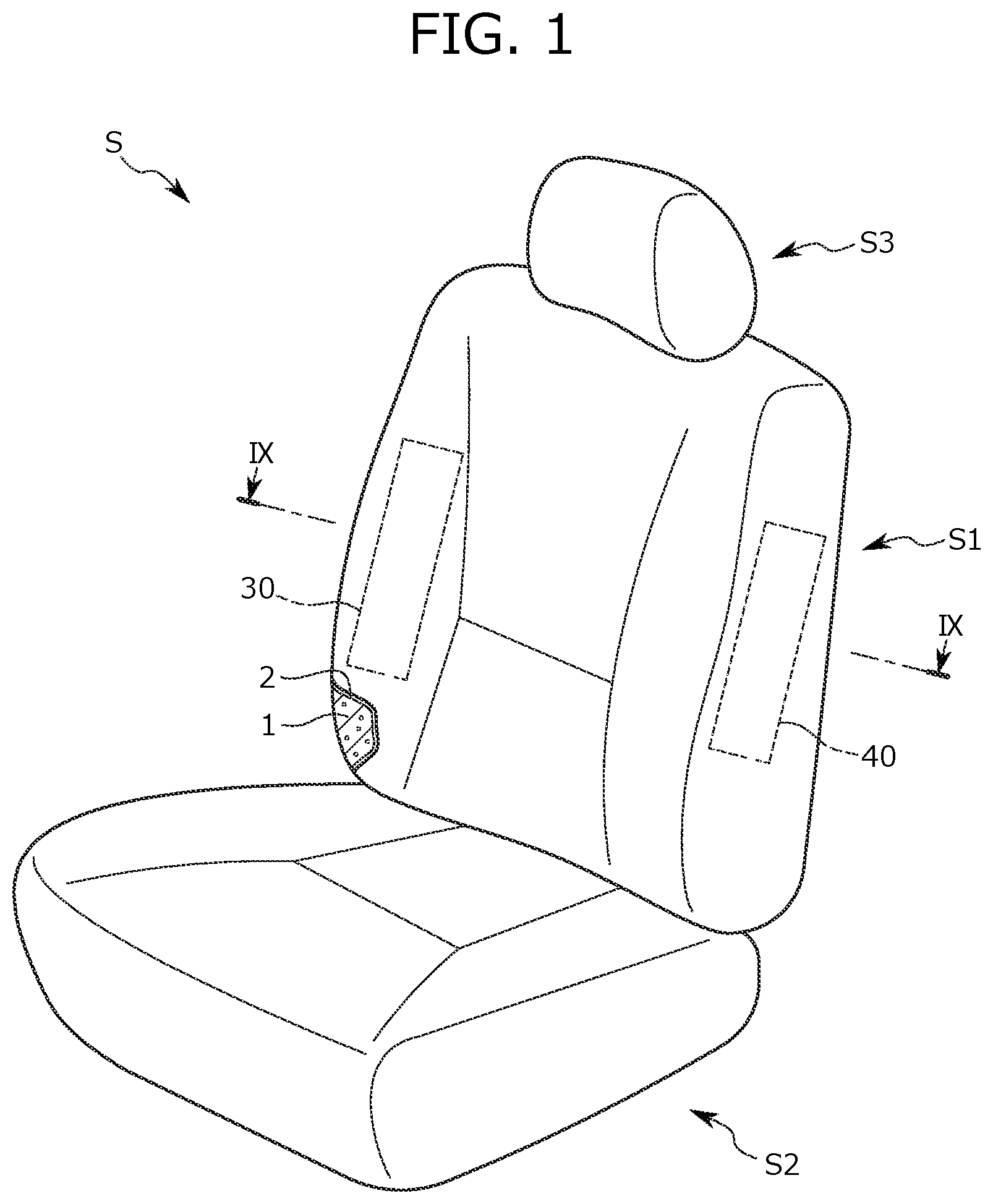
is a perspective view of a vehicle seat according to the present embodiment. is a perspective view of a seat back frame. is a right view of the seat back frame. is a left view of the seat back frame. is an enlarged view of a position in which an airbag module is attached to a pipe frame. is a cross-sectional view taken along a line VI-VI of . is a cross-sectional view taken along a line VII-VII of . is an enlarged view of a portion in which an airbag module is attached to a plate frame. is a cross-sectional view taken along a line IX-IX of . is a perspective view illustrating a modified example in which the arrangement of an inflator in a seat back frame is changed. is a right view of a seat back frame. is a perspective view of a retainer. is a perspective view of the seat back frame. is an enlarged view of a position in which an airbag module is attached to a pipe frame. is a cross-sectional view taken along a line XV-XV of . is a cross-sectional view taken along a line XVI-XVI of . is a perspective view of the retainer. is an enlarged view of a position in which an airbag module is attached to a pipe frame in a vehicle seat according to a modified example of the present invention.
DESCRIPTION OF EMBODIMENTS
<<1>> Hereinafter, a vehicle seat S according to an embodiment of the present invention (hereinafter, the embodiment) will be described with reference to to 10 . The vehicle seat S according to the embodiment is a vehicle seat which includes an airbag device provided in a side portion. Additionally, the embodiment to be described below is merely an example for easily understanding the present invention and does not limit the present invention. That is, the shapes, dimensions, arrangements, and the like of the members to be described below can be modified and improved without departing from the spirit of the present invention and the equivalents thereof are, of course, also included in the present invention. In the description below, the “front to back direction” means the front to back direction when viewed from the seated person of the vehicle seat S and corresponds to a direction matching a vehicle traveling direction. The “seat width direction” means a horizontal width direction of the vehicle seat S and matches the right and left direction when viewed from the seated person of the vehicle seat S. Further, the “up to down direction” means the height direction of the vehicle seat S and matches the up to down direction when the vehicle seat S is viewed from the front side. [Configuration of Vehicle Seat S] As illustrated in , the vehicle seat S includes a seat back S 1 which becomes a backrest portion, a seat cushion S 2 which becomes a seated portion, and a headrest S 3 which is disposed at an upper portion of the seat back S 1 and supports a head of an occupant. The seat back S 1 has a configuration in which a seat back frame 10 corresponding to a skeleton illustrated in is covered by a seat back pad 1 and the seat back pad 1 is further covered by a skin 2 . An airbag module 30 and an airbag module 40 are respectively provided inside the side portion of the seat back S 1 . In the present embodiment, the airbag module 40 is set to be closer to a door of a vehicle in relation to the airbag module 30 . That is, the airbag module 30 is referred to as a far-side airbag device and the airbag module 40 is referred to as a near-side airbag device. Additionally, the airbag module 30 which is the far-side airbag device is used to protect an occupant of the vehicle seat S from the collision with an occupant seated on a next seat. Further, the airbag module 40 which is the near-side airbag device is used to protect the occupant of the vehicle seat S from the collision with the door of the vehicle or the outside of the vehicle. In the present embodiment, an example in which the airbag module 30 corresponding to the far-side airbag device is disposed at the right side of the vehicle seat S and the airbag module 40 corresponding to the near-side airbag device is disposed at the left side thereof is described, but the arrangement of both modules is determined in response to the arrangement of the vehicle seat S in the vehicle and is not limited to the above-described example. [Configuration of Seat Back S 1 ] Next, a configuration of the seat back S 1 will be described with reference to to 9 . shows a perspective view of the seat back frame 10 which is a skeleton of the seat back S 1 . As illustrated in , the seat back frame 10 includes an inverse U-shaped pipe frame 11 , a pair of plate frames 12 which respectively forms end portions in the seat width direction, and a lower frame 15 which is bridged between the lower end portions of the pair of plate frames 12 . A side portion 11 A of the pipe frame 11 and an upper end portion of the plate frame 12 are respectively disposed to overlap each other in the up to down direction and the side portion 11 A of the pipe frame 11 and the upper end portion of the plate frame 12 are joined at a welded portion including a welded portion 50 A and a welded portion 50 B. Additionally, in the present embodiment, the side portion of the seat back frame 10 which includes the side portion 11 A of the pipe frame 11 and the plate frame 12 is referred to as a side frame 13 . The seat back frame 10 is provided with a cross member 14 which bridges the upper portion of the pipe frame 11 (that is, the upper portion of the side portion 11 A). The airbag module 30 is attached to the right side frame 13 through a bracket 20 . Additionally, since the bracket 20 is provided at a lower portion in relation to the welded portion 50 A and the welded portion 50 B corresponding to the joint portion between the pipe frame 11 and the plate frame 12 , it prevents rigidity of the joint portion from being increased more than necessary. Accordingly, the shock absorption of the seat back frame 10 is not disturbed by the attachment of the bracket 20 and the airbag module 30 . [Attachment Structure of Airbag Module 30 ] Hereinafter, an attachment structure of the airbag module 30 with respect to the bracket 20 will be described in detail with reference to and to 9 . As illustrated in , a side surface of the side portion 11 A of the right pipe frame 11 on the seat inner side is provided with a through-hole 11 B and a through-hole 11 C which are formed at the upper and lower sides. Here, the bracket 20 includes an attachment portion 21 which is attached to the through-hole 11 C of the pipe frame 11 and a back protrusion portion 22 which protrudes from the attachment portion 21 backward. Additionally, the back protrusion portion 22 includes a back extension portion 22 A which extends from the attachment portion 21 toward the seat back side and an outer extension portion 22 B which extends from the back extension portion 22 A toward the seat outer side. A screw 23 is fastened to the through-hole formed in the attachment portion 21 of the bracket 20 and the through-hole 11 C formed in the bracket 20 so that the bracket 20 is fixed to the pipe frame 11 . As illustrated in , 5 , and 7 , the airbag module 30 includes an airbag 31 , an inflator 32 , and a retainer 34 provided inside a casing 33 . The inflator 32 generates a gas when receiving an input of an operation signal via a harness 35 from a sensor detecting collision of the vehicle. Then, the inflator 32 expands and deploys the airbag 31 by injecting a generated gas into the airbag 31 . The retainer 34 is a plate member for attaching the airbag module 30 to the seat back frame 10 . The retainer 34 includes a flat plate portion 34 D which faces an outer surface 12 A of the plate frame 12 and a protrusion portion 34 A which protrudes from the casing 33 . As illustrated in , a stud bolt 36 A and a stud bolt 36 B which are provided in the inflator 32 protrude toward the seat inner side through the flat plate portion 34 D of the retainer 34 . Each of the stud bolt 36 A and the stud bolt 36 B passes through the through-hole formed in the plate frame 12 . Then, the inflator 32 , the retainer 34 , and the plate frame 12 are fixed by fastening a nut to the stud bolt 36 A from the seat inner side of the plate frame 12 . Meanwhile, the inflator 32 and the retainer 34 are fixed by fastening a nut 37 to the stud bolt 36 B. Additionally, the through-hole of the plate frame 12 through which the stud bolt 36 B passes has a diameter larger than that of the nut 37 and the retainer 34 and the plate frame 12 are not fixed at this portion. Further, a webbing clip 60 for fixing a webbing is attached to the plate frame 12 at a position interposing the stud bolt 36 A and the stud bolt 36 B in the vertical direction. Here, the webbing is a member that guides the deploying direction of the airbag 31 by covering the side portion of the airbag module 30 . As illustrated in , the outer extension portion 22 B of the bracket 20 is attached to the protrusion portion 34 A of the retainer 34 . Specifically, as illustrated in , the protrusion portion 34 A includes an inner extension portion 34 B which extends toward the seat inner side and an opening portion 34 C is formed from the center of the inner extension portion 34 B to the end portion on the seat inner side. Then, a bolt 24 passes through the through-hole formed in the outer extension portion 22 B of the bracket 20 and the opening portion 34 C and a cap nut 25 is fitted to an end portion 24 A of the bolt 24 to be fastened thereto. Accordingly, the bracket 20 and the retainer 34 are fixed. Additionally, according to the above-described configuration, the end portion 24 A of the bolt 24 faces the seat back side and the cap nut 25 can be fitted thereto from the seat back side. Further, since the end portion 24 A of the bolt 24 is covered by the cap nut 25 , it is possible to prevent the end portion 24 A of the bolt 24 from damaging the inside of the seat back S 1 . As illustrated in , a side portion on the arrangement side of the airbag module 30 in the seat back pad 1 of the seat back S 1 is provided with a storage portion 1 A in which a pad member is hollowed out. The airbag module 30 is disposed in the storage portion 1 A. In this way, since the storage portion 1 A for disposing the airbag module 30 therein is provided in the seat back pad 1 , it is possible to attach the airbag module 30 to the seat back frame 10 after the seat back pad 1 is assembled to the seat back frame 10 in the seat back S 1 . For this reason, it is possible to prevent the displacement of the airbag module 30 as compared with a case in which the seat back pad 1 is covered by the seat back frame 10 after the airbag module 30 is attached to the seat back frame 10 . Next, an attachment structure of the airbag module 40 with respect to the seat back frame 10 will be described. Additionally, the airbag module 40 faces an outer surface of a side plate 41 attached to the left side frame 13 of the seat back frame 10 to be attached. As illustrated in , the side plate 41 is fixed to the pipe frame 11 by threading a screw 42 into the through-hole of the pipe frame 11 on the seat inner side and the through-hole provided in the side plate 41 . Further, as illustrated in , the position of the upper end of the airbag module 30 is higher than the upper end of the side plate 41 to which the airbag module 40 is attached. That is, the upper end of the airbag module 30 is located at a position higher than the upper end of the airbag module 40 . According to the above-described vehicle seat S, since the bracket 20 for attaching the airbag module 30 is attached to the inner surface of the side frame 13 , it is possible to obtain a compact width of the attachment portion of the airbag module 30 in the right and left direction. Further, since the airbag module 30 is attached to the seat back side in relation to the attachment portion between the bracket 20 and the side frame 13 , it is possible to improve workability when assembling the airbag module 30 to the bracket 20 from the seat back side. Further, according to the vehicle seat S, it is possible to attach the airbag module 30 to both of the bracket 20 and the outer surface 12 A of the plate frame 12 . Accordingly, it is possible to strongly attach the airbag module 30 as compared with a case in which the airbag module 30 is attached to any one of the bracket 20 and the plate frame 12 . Further, according to the vehicle seat S, since the bracket 20 is attached to a position below the joint portion (the welded portion 50 A and the welded portion 50 B) between the pipe frame 11 and the plate frame 12 in the side frame 13 , that is, a position not overlapping the joint portion, it is possible to prevent improvement of rigidity of the side frame 13 . Accordingly, it is possible to maintain appropriate shock absorption of the side frame 13 even when the bracket 20 is attached. Further, according to the vehicle seat S, it is possible to set the direction of the attachment portion to the pipe frame 11 and the direction of the attachment portion to the airbag module 30 in the bracket 20 to be different from each other. Accordingly, it is possible to improve attachment workability by preventing interference between attachment positions of the bracket 20 and the pipe frame 11 and between attachment positions of the bracket 20 and the airbag module 30 . Further, according to the vehicle seat S, it is easy to attach the bracket 20 and the retainer 34 of the airbag module 30 from the seat back side by using the bolt 24 and the cap nut 25 . Further, since the end portion 24 A of the bolt 24 is covered by the cap nut 25 , it is possible to prevent the seat back pad 1 from being damaged by the end portion 24 A of the bolt 24 . Further, according to the vehicle seat S, it is possible to fit the opening portion 34 C of the retainer 34 to the bolt 24 from the seat outer side. Accordingly, it is possible to improve attachment workability of the airbag module 30 . Further, according to the vehicle seat S, since the storage portion 1 A which stores the airbag module 30 is provided in the side portion of the seat back pad 1 , the airbag module 30 can be disposed and attached in the storage portion 1 A of the seat back pad 1 even after the seat back pad is attached to the seat back frame 10 . In this way, since it is possible to attach the airbag module 30 after the seat back pad 1 is attached to the seat back frame 10 , it is possible to prevent the displacement of the airbag module 30 when attaching the seat back pad 1 . Accordingly, it is possible to improve the arrangement accuracy of the airbag module 30 . Other Embodiments Further, the present invention is not limited to the above-described embodiment. For example, as illustrated in , the inflator 32 may be disposed at the outside of the casing 33 of the airbag module 30 . At this time, the inflator 32 is disposed between a front wall portion 15 A which is located in the lower frame 15 on the seat front side to support a waist portion of an occupant and a back wall portion 15 B which is located on the seat back side. Additionally, the stud bolt 36 A and the stud bolt 36 B attached to the inflator 32 pass through the through-holes provided in the back wall portion 15 B and are fixed to the back wall portion 15 B by nuts. Further, the inflator 32 and the airbag are connected by a pipe 38 and a gas generated from the inflator 32 is injected to the airbag 31 through the pipe 38 . In this way, since the inflator 32 is disposed at the position of the lower frame 15 , it is possible to reduce the weight of the upper portion of the seat back frame 10 . Accordingly, it is possible to prevent the deformation of the seat back frame 10 in the event of collision of the vehicle. Further, since the inflator 32 is disposed between the front wall portion 15 A and the back wall portion 15 B of the lower frame 15 , it is possible to protect the inflator 32 from an external shock. <<2>> Next, the retainer 34 will be described in detail. As illustrated in , 7 , and 12 , the retainer 34 includes a first extension portion 134 A which protrudes from the casing 33 and extends toward the seat inner side and a second extension portion 134 B which faces the outer surface 12 A of the plate frame 12 . As illustrated in , the stud bolt 36 A and the stud bolt 36 B which are provided in the inflator 32 , passing through a first through-hole 134 G and a second through-hole 134 H formed in the second extension portion 134 B of the retainer 34 , protrude toward the seat inner side. Each of the stud bolt 36 A and the stud bolt 36 B passes through the through-hole formed in the plate frame 12 . Then, the inflator 32 , the retainer 34 , and the plate frame 12 are fixed by fastening a nut to the stud bolt 36 A from the seat inner side of the plate frame 12 . Meanwhile, the inflator 32 and the retainer 34 are fixed by fastening the nut 37 to the stud bolt 36 B. Additionally, the through-hole of the plate frame 12 through which the stud bolt 36 B passes has a diameter larger than that of the nut 37 and the retainer 34 and the plate frame 12 are not fixed at this portion. Further, the webbing clip 60 for fixing a webbing is attached to the plate frame 12 at a position interposing the stud bolt 36 A and the stud bolt 36 B in the vertical direction. Here, the webbing is a member that guides the deploying direction of the airbag 31 by covering the side portion of the airbag module 30 . As illustrated in , the outer extension portion 22 B of the bracket 20 is attached to the first extension portion 134 A of the retainer 34 . Specifically, as illustrated in , the first extension portion 134 A is provided with a notch portion 134 C which is notched from an end opening portion 134 D of the end portion on the seat inner side to a center opening portion 134 E at the center portion. Here, a bead portion 134 F which protrudes toward the seat back side is formed in the periphery of the notch portion 134 C in the first extension portion 134 A. In this way, since the first extension portion 134 A is provided with the bead portion 134 F, the strength of the first extension portion 134 A is improved. Then, the bolt 24 passes through the through-hole formed in the outer extension portion 22 B of the bracket 20 and the notch portion 134 C, and the cap nut 25 is fitted to the end portion 24 A of the bolt 24 to be fastened thereto. Accordingly, the bracket 20 and the retainer 34 are fixed. Additionally, according to the above-described configuration, the end portion 24 A of the bolt 24 faces the seat back side and the cap nut 25 can be fitted thereto from the seat back side. Further, since the end portion 24 A of the bolt 24 is covered by the cap nut 25 , it is possible to prevent the inside of the seat back S 1 from being damaged by the end portion 24 A of the bolt 24 . According to the above-described vehicle seat S, since the bracket 20 for attaching the airbag module 30 is attached to the inner surface of the side frame 13 , it is possible to obtain a compact width of the attachment portion of the airbag module 30 in the right and left direction. Further, since the airbag module 30 is attached to the seat back side in relation to the attachment portion between the bracket 20 and the side frame 13 , it is possible to improve workability when assembling the airbag module 30 to the bracket 20 from the seat back side. Further, it is possible to prevent the separation of the retainer 34 and the side frame 13 which are fixed to each other even when a force is applied to the retainer 34 in the inner direction of the seat and the up to down direction of the seat. Further, in the vehicle seat S, the retainer 34 is fixed to the bracket 20 attached to the side frame 13 by using the bolt 24 and the cap nut 25 . In this way, it is possible to easily perform an operation of attaching the retainer 34 to the side frame 13 . Further, according to the vehicle seat S, it is possible to attach the airbag module 30 to both of the bracket 20 and the outer surface 12 A of the plate frame 12 . Accordingly, it is possible to improve attachment rigidity as compared with a case in which the airbag module 30 is attached to any one of the bracket 20 and the plate frame 12 . Further, according to the vehicle seat S, since the opening width of the end opening portion 134 D of the notch portion 134 C is narrower than the opening width of the center opening portion 134 E through which the bolt 24 is inserted, it is possible to prevent the bolt 24 from being separated from the notch portion 134 C of the retainer 34 even when a force is applied to the retainer 34 in the outer direction of the seat after the retainer 34 is attached to the side frame 13 . Accordingly, it is possible to prevent the separation of the retainer 34 and the side frame 13 which are fixed to each other. Further, according to the vehicle seat S, since the bead portion 134 F is formed in the periphery of the notch portion 134 C in the first extension portion 134 A, it is possible to improve rigidity in the periphery of the attachment portion with the side frame 13 in the retainer 34 . Further, according to the vehicle seat S, since the retainer 34 is exposed from a gap between the upper end and the lower end of the casing 33 of the airbag module 30 , it is possible to obtain the airbag module 30 in a compact size. The vehicle seat according to the present invention includes a side frame which constitutes a side portion of a seat back frame and an airbag module which is attached to the side frame, in which the airbag module includes a retainer which is attached to the side frame, the retainer includes a first extension portion provided behind the side frame and extending to a seat inner side, the first extension portion is provided with a notch portion formed from an end portion on the seat inner side toward a seat outer side, and the retainer is fixed to the side frame by using an attachment member inserted through the notch portion. According to the above-described vehicle seat, it is possible to assemble the airbag module to the side frame of the seat back from the seat back side. Accordingly, it is possible to improve workability when attaching the airbag module disposed at the side portion of the vehicle seat from the seat back side. Further, it is possible to prevent the separation of the retainer and the side frame which are fixed to each other even when a force is applied to the retainer in the inner direction of the seat and the up to down direction of the seat. In the above-described vehicle seat, the retainer includes a second extension portion which is connected to the first extension portion and extends to the seat front side and the second extension portion is attached to the side frame. In this way, it is possible to attach the retainer to the side frame at two surfaces. For this reason, it is possible to improve attachment rigidity of the retainer and the side frame. In the above-described vehicle seat, the notch portion s fixed to the bracket attached to the side frame and extending toward the seat back side. In this way, since the bracket attached to the side frame and extending toward the seat back side and the retainer are attached, it is possible to simply fix the retainer and the side frame. In the above-described vehicle seat, the bracket is fixed to the retainer by a bolt inserted through the notch portion and a nut threaded to the bolt. In this way, the retainer is fixed to the bracket attached to the side frame by using the bolt and the nut. Accordingly, it is possible to easily perform an operation of attaching the retainer to the side frame. In the above-described vehicle seat, the nut is a cap nut which covers an end portion of the bolt. In this way, since the end portion of the bolt is covered by the cap nut, it is possible to prevent the seat inner portion from being damaged by the end portion of the bolt. In the above-described vehicle seat, the opening width of the end portion on the seat inner side of the notch portion is narrower than the opening width of the portion through which the bolt is inserted. In this way, it is possible to prevent the bolt from being separated from the notch portion of the retainer even when a force is applied to the retainer in the outer direction of the seat after the retainer is attached to the side frame. Accordingly, it is difficult to separate the retainer and the side frame which are fixed to each other. In the above-described vehicle seat, a bead is formed in the periphery of the notch portion in the first extension portion. In this way, it is possible to improve the rigidity in the periphery of the attachment portion with the side frame in the retainer. In the above-described vehicle seat, the airbag module includes the retainer, the airbag, the inflator supplying a gas to the airbag, and the casing covering the retainer, the airbag, and the inflator and the retainer is exposed from a gap between the upper end and the lower end of the casing. In this way, it is possible to obtain the airbag module in a compact size. The above-described vehicle seat includes a seat back pad which is placed on the seat back frame and the seat back pad includes a storage portion which is opened in the side portion toward the seat outer side and stores the airbag module. In this way, it is possible to attach the airbag module by disposing the airbag module in the storage portion of the seat back pad after the seat back pad is attached to the seat back frame. <<3>> Next, another example of an attachment structure of the bracket 20 and a retainer 234 will be described. The retainer 234 is a plate member for attaching the airbag module 30 to the seat back frame 10 . As illustrated in , 14 , 16 , and 17 , the retainer 234 includes an inner extension portion 234 A which protrudes from the casing 33 and extends toward the seat inner side and a front extension portion 234 B which faces the outer surface 12 A of the plate frame 12 . Here, a through-hole is formed at the center portion of the inner extension portion 234 A and the bolt 24 (an example of the attachment portion) inserted through the through-hole is attached so that the end portion of the bolt faces the seat back side (that is, the opposite side of the extension direction of the front extension portion 234 B). For example, when the inner extension portion 234 A is formed of metal, the bolt 24 may be attached to the inner extension portion 234 A by welding. As illustrated in , the stud bolt 36 A and the stud bolt 36 B provided in the inflator 32 protrude toward the seat inner side through the first through-hole 234 C and the second through-hole 234 D formed in the front extension portion 234 B of the retainer 234 . Each of the stud bolt 36 A and the stud bolt 36 B passes through the through-hole formed in the plate frame 12 . Then, a nut is fastened to the stud bolt 36 A from the seat inner side of the plate frame 12 so that the inflator 32 , the retainer 234 , and the plate frame 12 are fixed. Meanwhile, the nut 37 is fastened to the stud bolt 36 B so that the inflator 32 and the retainer 234 are fixed. Additionally, the through-hole of the plate frame 12 through which the stud bolt 36 B passes has a diameter larger than that of the nut 37 and the retainer 234 and the plate frame 12 are not fixed at this portion. Further, the webbing clip 60 for fixing a webbing is attached to the plate frame 12 at a position interposing the stud bolt 36 A and the stud bolt 36 B in the vertical direction. Here, the webbing is a member that guides the deploying direction of the airbag 31 by covering the side portion of the airbag module 30 . As illustrated in , a side surface of the side portion 11 A of the right pipe frame 11 on the seat inner side is provided with the through-hole 11 B and the through-hole 11 C which are formed at the upper and lower sides. Here, the bracket 20 includes the attachment portion 21 which is attached to the through-hole 11 C of the pipe frame 11 and the back protrusion portion 22 which protrudes from the attachment portion 21 backward. Additionally, the back protrusion portion 22 includes the back extension portion 22 A which extends from the attachment portion 21 toward the seat back side and the outer extension portion 22 B which extends from the back extension portion 22 A toward the seat outer side. As illustrated in , a screw 23 is fastened to the through-hole formed in the attachment portion 21 of the bracket 20 and the through-hole 11 C formed in the bracket 20 so that the bracket 20 is fixed to the pipe frame 11 . As illustrated in , a bead portion which is recessed toward the seat outer side is formed at the center portion of the back extension portion 22 A. Accordingly, it is possible to improve the strength of the back extension portion 22 A. As illustrated in , the inner extension portion 234 A of the retainer 234 is attached to the outer extension portion 22 B. Specifically, as illustrated in , the outer extension portion 22 B is provided with a notch portion 22 C which is notched from an end opening portion 22 D of the end portion on the seat outer side to a center opening portion 22 E of the center portion. Here, a bead portion 22 F which protrudes toward the seat back side is formed in the periphery of the notch portion 22 C in the outer extension portion 22 B. In this way, since the outer extension portion 22 B is provided with the bead portion 22 F, the strength of the outer extension portion 22 B is improved. Then, the bolt 24 fixed to the retainer 234 passes through the notch portion 22 C formed in the outer extension portion 22 B of the bracket 20 from the end opening portion 22 D toward the center opening portion 22 E. Then, the cap nut 25 is fitted and fastened to the end portion 24 A of the bolt 24 . Accordingly, the bracket 20 and the retainer 234 are fixed. Additionally, according to the above-described configuration, the end portion 24 A of the bolt 24 faces the seat back side and the cap nut 25 can be fitted thereto from the seat back side. Further, since the end portion 24 A of the bolt 24 is covered by the cap nut 25 , it is possible to prevent the inside of the seat back S 1 from being damaged by the end portion 24 A of the bolt 24 . According to the above-described vehicle seat S, since the bracket 20 for attaching the airbag module 30 is attached to the inner surface of the side frame 13 , it is possible to obtain a compact width of the attachment portion of the airbag module 30 in the right and left direction. Further, since the airbag module 30 is attached to the seat back side in relation to the attachment portion of the bracket 20 and the side frame 13 , it is possible to improve workability when assembling the airbag module 30 to the bracket 20 from the seat back side. Further, it is possible to prevent the separation of the retainer 234 and the side frame 13 which are fixed to each other even when a force is applied to the retainer 234 in the inner direction of the seat and the up to down direction of the seat. Further, in the vehicle seat S, the retainer 234 is fixed to the bracket 20 attached to the side frame 13 by using the bolt 24 and the cap nut 25 . In this way, it is possible to easily perform an operation of attaching the retainer 234 to the side frame 13 . Further, according to the vehicle seat S, it is possible to attach the airbag module 30 to both of the bracket 20 and the outer surface 12 A of the plate frame 12 . Accordingly, it is possible to improve attachment rigidity as compared with a case in which the airbag module 30 is attached to any one of the bracket 20 and the plate frame 12 . Further, according to the vehicle seat S, since the opening width of the end opening portion 22 D in the notch portion 22 C of the bracket 20 is narrower than the opening width of the center opening portion 22 E through which the bolt 24 is inserted, it is possible to prevent the bolt 24 from being separated from the notch portion 22 C of the bracket 20 even when a force is applied to the retainer 234 in the outer direction of the seat after the retainer 234 is attached to the side frame 13 . Accordingly, it is possible to prevent the separation of the retainer 234 and the side frame 13 which are fixed to each other. Further, according to the vehicle seat S, since the bead portion 22 F is formed in the periphery of the notch portion 22 C in the outer extension portion 22 B, it is possible to improve the rigidity in the periphery of the attachment portion with the retainer 234 in the bracket 20 . Further, according to the vehicle seat S, the retainer 234 is exposed from a gap between the upper end and the lower end of the casing 33 of the airbag module 30 , it is possible to obtain the airbag module 30 in a compact size. Further, according to the vehicle seat S, it is possible to fit the bolt 24 attached to the retainer 234 from the outside of the notch portion 22 C of the bracket 20 . Accordingly, it is possible to improve the attachment workability of the airbag module 30 . Next, the vehicle seat S according to a modified example of the present invention will be described with reference to . In the modified example illustrated in , a bracket 120 has a shape different from that of the bracket 20 . That is, as illustrated in , the bracket 120 is different from the bracket 20 in that the outer extension portion 22 B of the bracket 120 is provided with not the notch portion 22 C but a through-hole 22 G. Additionally, since the vehicle seat S according to the modified example has a common point with the above-described embodiment in other points, a description of the common points is omitted. Here, an operation of attaching the bracket 120 and the retainer 234 of the vehicle seat S according to the modified example will be described. First, the bolt 24 fixed to the retainer 234 is inserted to the through-hole 22 G formed in the outer extension portion 22 B of the bracket 120 toward the seat back side. Then, the cap nut 25 is fitted and fastened to the end portion 24 A of the bolt 24 . Accordingly, the bracket 120 and the retainer 234 are fixed. Also in the vehicle seat S according to the modified example, since the retainer 234 of the airbag module 30 can be assembled to the side frame 13 from the seat back side, workability can be improved. Further, in the above-described embodiment, the bracket 20 is attached to the pipe frame 11 by the screw 23 , but the bracket 20 may be attached to the pipe frame 11 by welding. Additionally, various welding methods such as arc welding and laser welding may be used for welding. Further, a method of fixing the bracket 20 and the retainer 234 is not limited to the above-described embodiment. For example, the bracket 20 and the retainer 234 may be fixed by welding the back protrusion portion 22 of the bracket 20 and the bolt 24 integrated with the retainer 234 . Further, for example, the retainer 234 and the bracket 20 may be fixed, by fitting a push nut to the rod, in a state where the retainer 234 is provided with a rod which protrudes from the inner extension portion 234 A backward and the rod is inserted through the notch portion 22 C of the back protrusion portion 22 . The vehicle seat according to the present invention is a vehicle seat including a side frame which constitutes a side portion of a seat back frame, an airbag module which includes a retainer attached to the side frame, and a bracket which connects the side frame and the airbag module, the bracket includes an outer extension portion which is provided behind the side frame and extends toward a seat outer side, the outer extension portion is provided with a notch portion which is formed from an end portion on the seat outer side toward a seat inner side, the retainer includes an inner extension portion which extends toward the seat inner side, and the inner extension portion and the outer extension portion are fixed by using an attachment portion inserted through the notch portion. According to the above-described vehicle seat, it is possible to assemble the airbag module from the seat back side. Further, it is possible to simply attach the airbag module to the side frame in the inner direction of the seat. Further, it is possible to prevent the airbag module from being separated from the side frame even when a shock is applied in the inner direction of the seat and the up to down direction of the seat after the airbag module is attached to the side frame. Further, in the above-described vehicle seat, the inner extension portion is disposed behind the outer extension portion. In this way, it is possible to perform an operation of fixing the bracket and the retainer from the back side of the bracket. Further, in the above-described vehicle seat, the retainer includes a front extension portion which is connected to the inner extension portion and extends toward the seat front side and the front extension portion is attached to the side frame. In this way, it is possible to attach the retainer to the side frame at two surfaces. For this reason, it is possible to improve the attachment rigidity of the retainer and the side frame. Further, in the above-described vehicle seat, the bracket is attached to a side surface of the side frame on the seat inner side. In this way, it is possible to obtain a compact width of the attachment portion of the airbag module in the right and left direction. Further, in the above-described vehicle seat, the retainer includes the attachment portion and the attachment portion includes a portion which protrudes from the inner extension portion backward. In this way, it is possible to easily perform an operation of fixing the bracket and the retainer to each other. Further, in the above-described vehicle seat, the bracket is fixed to the retainer by a bolt inserted through the notch portion and a nut threaded to the bolt. In this way, the retainer is fixed to the bracket attached to the side frame by using the bolt and the nut. Accordingly, it is possible to easily perform an operation of attaching the retainer to the side frame. In the above-described vehicle seat, the nut is a cap nut which covers an end portion of the bolt. In this way, since the end portion of the bolt is covered by the cap nut, it is possible to prevent the seat inner portion from being damaged by the end portion of the bolt. Further, in the above-described vehicle seat, the outer extension portion is provided with a bead formed in the periphery of the notch portion. In this way, it is possible to prevent the bolt from being separated from the notch portion of the retainer even when a force is applied to the retainer in the outer direction of the seat after the retainer is attached to the side frame. Accordingly, it is difficult to separate the retainer and the side frame which are fixed to each other. Further, in the above-described vehicle seat, the airbag module includes the retainer, the airbag, the inflator supplying a gas to the airbag, and the casing covering the retainer, the airbag, and the inflator and the retainer is exposed from a gap between the upper end and the lower end of the casing. In this way, it is possible to improve the rigidity in the periphery of the attachment portion with the side frame in the retainer. Further, it is preferred that the above-described vehicle seat includes the seat back pad which is placed on the seat back frame and the seat back pad includes the storage portion which is opened in the side portion toward the seat outer side and stores the airbag module. In this way, it is possible to obtain the airbag module in a compact size. Further, it is preferred that, in the above-described vehicle seat, the side frame includes a cylindrical pipe frame and a plate-shaped plate frame attached to a lower portion of the pipe frame, and the airbag module is attached to a side surface of the plate frame on a seat outer side. In this way, it is possible to attach the airbag module to both of the bracket and the side surface of the plate frame on the seat outer side. Accordingly, it is possible to strongly attach the airbag module to the seat cushion frame as compared with a case in which the airbag module is attached to any one of the bracket and the plate frame. REFERENCE SIGNS LIST S: VEHICLE SEAT S 1 : SEAT BACK S 2 : SEAT CUSHION S 3 : HEADREST 1 : SEAT BACK PAD 1 A: STORAGE PORTION 2 : SKIN 10 : SEAT BACK FRAME 11 : PIPE FRAME (UPPER FRAME) 11 A: SIDE PORTION 11 B: THROUGH-HOLE 11 C: THROUGH-HOLE 11 D: CONNECTION PORTION 12 : PLATE FRAME (PLATE FRAME MEMBER, FIRST PLATE FRAME, SECOND PLATE FRAME) 12 A: OUTER SURFACE 12 B: REAR FLANGE 13 : SIDE FRAME 14 : CROSS MEMBER 15 : LOWER FRAME 15 A: FRONT WALL PORTION 15 B: BACK WALL PORTION 16 : PRESSURE RECEIVING MEMBER 16 A: PLANE-SHAPED PORTION 16 B: CONNECTING MEMBER 20 : BRACKET 21 : ATTACHMENT PORTION 21 A: INNER BENT PORTION 22 : BACK PROTRUSION PORTION 22 A: BACK EXTENSION PORTION 22 B: OUTER EXTENSION PORTION 22 C: NOTCH PORTION 22 D: END OPENING PORTION 22 E: CENTER OPENING PORTION 22 F: BEAD PORTION 22 G: THROUGH-HOLE 22 H: RELIEF PORTION 23 : SCREW 24 : BOLT 24 A: END PORTION 25 : CAP NUT 30 : AIRBAG MODULE 31 : AIRBAG 32 : INFLATOR 33 : CASING 34 : RETAINER 34 A: PROTRUSION PORTION 34 B: INNER EXTENSION PORTION 34 C: OPENING PORTION 34 D: FLAT PLATE PORTION 35 : HARNESS 36 A: STUD BOLT 36 B: STUD BOLT 37 : NUT 38 : PIPE 40 : AIRBAG MODULE 41 : SIDE PLATE 42 : SCREW 50 A: WELDED PORTION 50 B: WELDED PORTION 60 : WEBBING CLIP 120 : BRACKET 134 A: FIRST EXTENSION PORTION 134 B: SECOND EXTENSION PORTION 134 C: NOTCH PORTION 134 D: END OPENING PORTION 134 E: CENTER OPENING PORTION 134 F: BEAD PORTION 134 G: FIRST THROUGH-HOLE 134 H: SECOND THROUGH-HOLE 234 : RETAINER 234 A: INNER EXTENSION PORTION 234 B: FRONT EXTENSION PORTION 234 C: FIRST THROUGH-HOLE 234 D: SECOND THROUGH-HOLE
Figures (18)
Citations
This patent cites (46)
- US3779577
- US5348342
- US5503428
- US5542696
- US5651582
- US5735572
- US5788272
- US5799971
- US5845932
- US5860673
- US5868420
- US5913536
- US6220624
- US6382665
- US7350803
- US8162394
- US10239430
- US2006/0175812
- US2012/0043791
- US2013/0270878
- US2015/0123435
- US2015/0251571
- US2016/0009248
- US2016/0221482
- US2018/0147959
- US2019/0100121
- US2019/0248320
- US2021/0316690
- US2023/0303025
- USH09-132102
- USH09-150705
- USH09-220994
- USH09-315256
- USH10-181500
- US2000-043669
- US2001-80445
- US2008-030528
- US2008-201298
- US2012-140044
- US2015-024771
- US5669567
- US2015-051770
- US2016-020142
- US6880390
- US2000/006426
- US2010/131322