Abstract
A driving assistance apparatus of the present embodiment is a driving assistance apparatus to be attached to a handlebar of a mobile body, the driving assistance apparatus including: a housing unit configured to hold a mobile information terminal; and a drive recorder unit configured to record surroundings of a driver of the mobile body, the drive recorder unit being provided on a back side of the housing unit when seen from a driver of the mobile body, with a vacant space portion interposed therebetween, in which heat from the drive recorder unit is dissipated outside from the vacant space portion.
Claims (5)
1 . A driving assistance apparatus to be attached to a handlebar of a mobile body, the driving assistance apparatus comprising: a housing unit configured to hold a mobile information terminal; and a drive recorder unit configured to record surroundings of a driver of the mobile body, the drive recorder unit being provided on a back side of the housing unit when seen from a driver of the mobile body, with a curved vacant space portion, into which external wind is taken by travel of the mobile body, interposed therebetween, wherein heat from the drive recorder unit is dissipated outside from the vacant space portion.
Show 4 dependent claims
2 . The driving assistance apparatus according to claim 1 , wherein the drive recorder unit is provided with a heat dissipation body on an interface with the vacant space portion.
3 . The driving assistance apparatus according to claim 2 , further comprising a Peltier device between the heat dissipation body and a circuit substrate of the drive recorder unit, the Peltier device comprising a heat absorption surface and a heat dissipation surface, wherein the heat absorption surface is arranged on a circuit substrate side of the drive recorder unit, and the heat dissipation surface is arranged on a heat dissipation body side.
4 . The driving assistance apparatus according to claim 2 , wherein a part of the housing unit projects to a drive recorder unit side.
5 . The driving assistance apparatus according to claim 4 , wherein a tip part of the part of the housing unit is recessed from a bottom part of the drive recorder unit.
Full Description
Show full text →
CROSS REFERENCE TO RELATED APPLICATION
This application is based upon and claims the benefit of priority from Japanese patent application No. 2024-046930, filed on Mar. 22, 2024, the disclosure of which is incorporated herein in its entirety by reference.
BACKGROUND
The present disclosure relates to a driving assistance apparatus. Japanese Utility Model No. 3237204 discloses a motorcycle-attachable mobile phone holder in which a mobile phone and a dashboard camera are integrally arranged.
SUMMARY
In the mobile phone holder disclosed in Japanese Utility Model No. 3237204, since the mobile phone and the dashboard camera are very close to each other, there is a possibility that the mobile phone fails due to heat from the dashboard camera. A driving assistance apparatus according to the present embodiment is a driving assistance apparatus to be attached to a handlebar of a mobile body, the driving assistance apparatus including: a housing unit configured to hold a mobile information terminal; and a drive recorder unit configured to record surroundings of a driver of the mobile body, the drive recorder unit being provided on a back side of the housing unit when seen from a driver of the mobile body, with a vacant space portion interposed therebetween, in which heat from the drive recorder unit is dissipated outside from the vacant space portion.
BRIEF DESCRIPTION OF THE DRAWINGS
The above and other aspects, advantages and features will be more apparent from the following description of certain embodiments taken in conjunction with the accompanying drawings, in which: is a sectional view of a driving assistance apparatus according to a first embodiment; is a perspective view of the driving assistance apparatus according to the first embodiment; is a perspective view of the driving assistance apparatus according to the first embodiment; is an xz plan view of a driving assistance apparatus according to a comparative example; shows sectional views of drive recorder units in the driving assistance apparatus according to the first embodiment and in the driving assistance apparatus according to the comparative example; shows sectional views of the driving assistance apparatus according to the first embodiment; and is an xy plan view showing an example of a heat dissipation body.
DETAILED DESCRIPTION
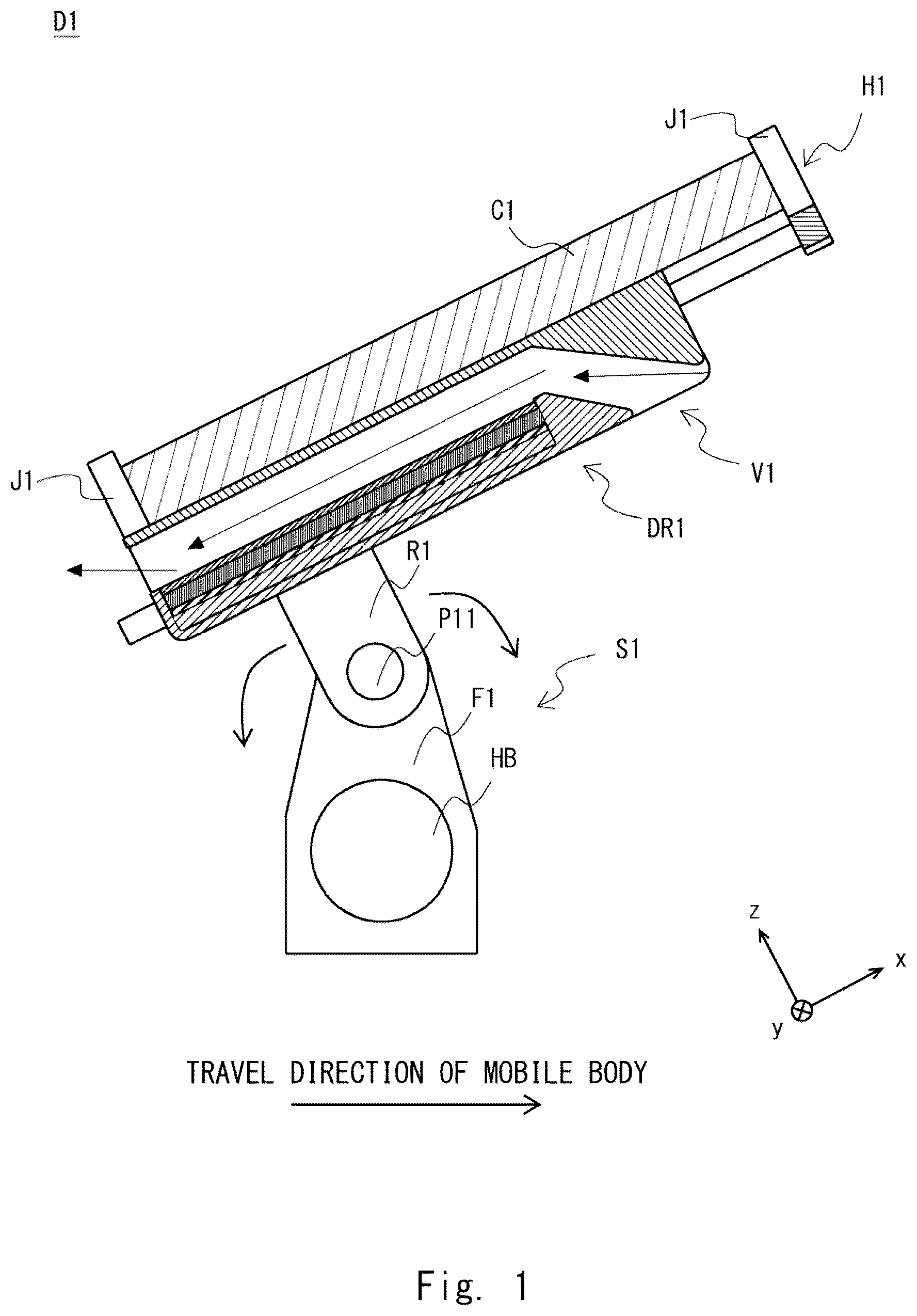
An embodiment of the present disclosure will be described below with reference to drawings. In the drawings, the same or corresponding components are given the same reference sign, and duplicate description will be omitted as necessary for clarification of description. Further, some reference signs are omitted in order to avoid the drawings from being complicated. It should be noted that each of the drawings below is schematic, and relationships between thicknesses and plane dimensions, a thickness ratio among layers, and the like are different from actual ones. Therefore, specific thicknesses and dimensions should be determined in consideration of the description below. Further, it goes without saying that the drawings also include such a part that the dimension relationship and ratio are different among the drawings. As a matter of course, the right-handed xyz Cartesian coordinates shown in each drawing are merely for convenience to describe positional relationships among components. In general, the positive z-axis indicates vertically upward, and the xy plane indicates a horizontal plane. First Embodiment Configuration of Driving Assistance Apparatus First, a configuration of a driving assistance apparatus D 1 according to a first embodiment will be described with reference to to 3 . is a sectional view of the driving assistance apparatus D 1 according to the first embodiment. are perspective views of the driving assistance apparatus D 1 according to the first embodiment. are diagrams showing a state in which a mobile information terminal C 1 is held by a housing unit H 1 . is a diagram showing a state in which the mobile information terminal C 1 is not held by the housing unit H 1 . As shown in , the driving assistance apparatus D 1 includes the housing unit H 1 , a drive recorder unit DR 1 , and a support unit S 1 . Support Unit First, the support unit S 1 will be described. As shown in to 3 , the support unit S 1 is configured with a rotation mechanism unit R 1 and a fixation unit F 1 . As shown in to 3 , the fixation unit F 1 is attached and fixed to a handlebar HB of a mobile body. The mobile body is a mobile body with a handlebar and is, for example, a two-wheeled vehicle or a micromobility. A driver can add a dashboard camera function to the mobile body by attaching the fixation unit F 1 of the driving assistance apparatus D 1 to the handlebar of the mobile body, and it is very convenient. As shown in to 3 , the rotation mechanism unit R 1 is connected to the fixation unit F 1 via a pinning portion P 11 . More specifically, as shown in , the rotation mechanism unit R 1 has a structure of being rotatable around the pinning portion P 1 in the direction of an arrow. By the rotation mechanism unit R 1 rotating, an installation position of the mobile information terminal C 1 held by the housing unit H 1 to be described later can be adjusted. Alternatively, the pinning portion P 11 may be modified to have a ball joint structure to seamlessly adjust the installation position of the mobile information terminal C 1 . Housing Unit Next, the housing unit H 1 will be described. As shown in , the housing unit H 1 holds the mobile information terminal C 1 . As shown in , the housing unit H 1 includes holding portions J 1 , an extendable portion E 1 , and a mounting portion M 1 . As shown in , the mounting portion M 1 (see ) is provided with the mobile information terminal C 1 mounted thereon. As shown in , the housing unit H 1 holds the mobile information terminal C 1 with four holding portions J 1 . In other words, the mounting portion M 1 holds the bottom part of the mobile information terminal C 1 to support the bottom part, and the holding portions J 1 hold the corners of the mobile information terminal C 1 to support the corners. As shown in , the extendable portion E 1 is a mechanism that is extendable and contractible in the directions of an arrow. As shown in , two holding portions J 1 (on the positive x-axis direction side) slide in the directions of the arrow, accompanying extension or contraction of the extendable portion E 1 . Thereby, the housing unit H 1 can hold the mobile information terminal C 1 according to the size and shape of the mobile information terminal C 1 . Though the four holding portions J 1 are provided to support the corners of the mobile information terminal C 1 in the example shown in to 3 , the present disclosure is not limited thereto. Holding portions may be provided on the housing unit H 1 to support a side (an xz plane) of the mobile information terminal C 1 . Drive Recorder Unit Next, the drive recorder unit DR 1 will be described. The drive recorder unit DR 1 records surroundings of the driver of the mobile body. As shown in to 3 , the drive recorder unit DR 1 is provided on the back side of the housing unit H 1 (the negative z-axis direction side in ). In general, the driver of the mobile body is located on the positive z-axis direction side of the mobile information terminal C 1 . Thereby, the drive recorder unit DR 1 can be said to be on the back side of the housing unit H 1 when seen from the driver of the mobile body. A heat dissipation mechanism of the drive recorder unit DR 1 will be described later. As shown in to 3 , in the driving assistance apparatus D 1 , the drive recorder unit DR 1 is provided on the back side of the housing unit H 1 on which the mobile information terminal C 1 is to be installed. In other words, in the driving assistance apparatus D 1 , the mobile information terminal C 1 and the drive recorder unit DR 1 are integrally arranged. Therefore, it is possible to install the driving assistance apparatus D 1 on a space-restricted mobile body such as two-wheeled vehicle, saving space. Vacant Space Portion Next, a vacant space portion V 1 will be described. As shown in to 3 , the vacant space portion V 1 is provided between the housing unit H 1 and the drive recorder unit DR 1 . A distance from the bottom surface of the housing unit H 1 to the top surface of the drive recorder unit DR 1 , that is, a width of the vacant space portion V 1 is set to a predetermined width, for example, according to the installation space of the driving assistance apparatus D 1 on the mobile body. As shown in , the wind passes through the vacant space portion V 1 in a direction opposite to the travel direction of the mobile body (the direction of arrows). As the travel speed of the mobile body increases, the flow rate and speed of the wind taken into the vacant space portion V 1 increases. By increasing the width of the vacant space portion V 1 , the flow rate and speed of the wind taken into the vacant space portion V 1 increases. Driving Assistance Apparatus According to Comparison Example Here, a driving assistance apparatus according to a comparison example will be described with reference to . is an xz plan view of the driving assistance apparatus according to the comparative example. In comparison with the driving assistance apparatus D 1 shown in to 3 , a driving assistance apparatus D 2 shown in is not provided with the vacant space portion V 1 . Except for that, the configuration is similar to that of the driving assistance apparatus D 1 shown in to 3 , and, therefore, description thereof will be omitted. The drive recorder unit DR 1 generates heat as it records the surroundings of the driver of the mobile body. Therefore, the drive recorder unit DR 1 dissipates the heat outside. In other words, the drive recorder unit DR 1 dissipates the heat in the z-axis direction (positive and negative directions) as indicated by arrows in . Due to the heat (in the positive z-axis direction) transmitted from the drive recorder unit DR 1 to the housing unit H 1 , the temperature of the housing unit H 1 increases. Thereby, the temperature of the mobile information terminal C 1 also increases. Therefore, there is a possibility that the mobile information terminal C 1 fails due to the heat from the drive recorder unit DR 1 . The mobile information terminal C 1 also generates heat as it is used. Therefore, the mobile information terminal C 1 also dissipates the heat outside. Due to the heat transmitted from the mobile information terminal C 1 to the housing unit H 1 , the temperature of the housing unit H 1 increases. Thereby, the temperature of the drive recorder unit DR 1 also increases. Therefore, there is also a possibility that the drive recorder unit DR 1 fails due to the heat from the mobile information terminal C 1 . Heat Dissipation From Vacant Space Portion In the driving assistance apparatus D 1 according to the first embodiment, however, the vacant space portion V 1 is provided between the housing unit H 1 and the drive recorder unit DR 1 as described before. Thereby, it is possible to prevent the heat from the drive recorder unit DR 1 from being transmitted to the housing unit H 1 . Therefore, it is possible to prevent the mobile information terminal C 1 from failing due to the heat from the drive recorder unit DR 1 . Further, it is also possible to prevent the heat from the mobile information terminal C 1 from being transmitted to the drive recorder unit DR 1 . In other words, by providing the vacant space portion V 1 between the housing unit H 1 and the drive recorder unit DR 1 , it is possible to prevent the heat from being transmitted from one of the mobile information terminal C 1 and the drive recorder unit DR 1 to the other. Therefore, in the driving assistance apparatus D 1 , it is possible to prevent failure of the drive recorder unit DR 1 and the mobile information terminal C 1 irrespective of travel of the mobile body. Here, the driving assistance apparatus D 1 is a driving assistance apparatus to be provided on a mobile body provided with a handlebar. A mobile body with a handlebar is not isolated from an external environment unlike an automobile. Therefore, the driving assistance apparatus D 1 is directly affected by the external environment. The external environment is, for example, an environment related to the weather such as wind, rain, snow, temperature, and sunlight. Due to the wind taken into the vacant space portion V 1 , it becomes easy for the driving assistance apparatus D 1 to dissipate the heat from the drive recorder unit DR 1 outside. Further, it is also possible for the driving assistance apparatus D 1 to cool the drive recorder unit DR 1 and the mobile information terminal C 1 by the wind taken into the vacant space portion V 1 . The wind may be taken into the vacant space portion V 1 by the wind blowing or by the mobile body traveling. In the case of a strong wind, since the flow rate and speed of the wind taken into the vacant space portion V 1 increases, the dissipation of heat to the outside and cooling described above increase more. Further, since the flow rate and speed of the wind taken into the vacant space portion V 1 increases as the travel speed of the mobile body increases, the dissipation of heat to the outside and cooling described above increase more. Thus, the driving assistance apparatus D 1 enhances the dissipation of heat to the outside by the drive recorder unit DR 1 and the mobile information terminal C 1 and cooling thereof, by utilizing being directly affected by the external environment. In the driving assistance apparatus D 1 , when the mobile body is not used, the mounting portion M 1 is exposed to sunlight because the mobile information terminal C 1 is not attached. In the driving assistance apparatus D 1 , the drive recorder unit DR 1 is provided on the back side of the housing unit H 1 (the negative z-axis direction side in ), that is, on the back side of the mounting portion M 1 (see ). Since the mounting portion M 1 plays a role of a sunshade, it is possible to prevent the drive recorder unit DR 1 from being directly exposed to sunlight. Therefore, it is possible to prevent increase in the temperature of the drive recorder unit DR 1 . Heat Dissipation Mechanism of Drive Recorder Unit Here, heat dissipation mechanisms of drive recorder units will be described in detail with reference to . shows sectional views of the drive recorder unit DR 1 in the driving assistance apparatus D 1 according to the first embodiment and a drive recorder unit DR 2 in the driving assistance apparatus D 2 according to the comparative example. The upper part of shows a sectional view of the drive recorder unit DR 1 of the driving assistance apparatus D 1 according to the first embodiment. The lower part of shows a sectional view of the drive recorder unit DR 2 of the driving assistance apparatus D 2 according to the comparative example. The sectional view in the upper part of is an enlarged view of the sectional view of the drive recorder unit DR 1 of . First, the heat dissipation mechanism of the drive recorder unit DR 2 of the driving assistance apparatus D 2 according to the comparison example will be described with reference to the lower part of . As shown in the lower part of , the drive recorder unit DR 2 is configured with casings 13 , a heat dissipation body 10 , and a circuit substrate 12 . As shown in the lower part of , the heat dissipation body 10 and the circuit substrate 12 are arranged between the casings 13 . As shown in the lower part of , in the drive recorder unit DR 2 , the casing 13 , the circuit substrate 12 , the heat dissipation body 10 , and the casing 13 are arranged in that order from the bottom part of the drive recorder unit DR 2 . Next, the heat dissipation mechanism of the drive recorder unit DR 1 of the driving assistance apparatus D 1 according to the first embodiment will be described with reference to the upper part of . As shown in the upper part of , the drive recorder unit DR 1 is configured with the casing 13 , the heat dissipation body 10 , a Peltier device 11 , and the circuit substrate 12 . As shown in the upper part of , the heat dissipation body 10 is provided on the interface with the vacant space portion V 1 (see to 3 ). The Peltier device 11 is provided between the heat dissipation body 10 and the circuit substrate 12 . As shown in the upper part of , in the drive recorder unit DR 1 , the casing 13 , the circuit substrate 12 , the Peltier device 11 , and the heat dissipation body 10 are arranged in that order from a bottom part of the drive recorder unit DR 1 . The heat dissipation body 10 is made of metallic material, for example, aluminum. The heat dissipation body 10 dissipates the heat from the drive recorder unit DR 1 into the vacant space portion V 1 (see ). The Peltier device 11 absorbs heat from the circuit substrate 12 and dissipates the heat to the heat dissipation body 10 . The Peltier device 11 has a heat dissipation surface and a heat absorption surface. The heat absorption surface of the Peltier device 11 is arranged on the circuit substrate 12 side. The heat dissipation surface of the Peltier device 11 is arranged on the heat dissipation body 10 side. The heat from the circuit substrate 12 is absorbed by the heat absorption surface of the Peltier device 11 . Then the heat absorbed by the heat absorption surface of the Peltier device 11 is dissipated upward (in the positive z-axis direction) by the heat dissipation surface of the Peltier device 11 . The heat dissipated from the heat dissipation surface of the Peltier device 11 is dissipated by the heat dissipation body 10 into the vacant space portion V 1 (see ). In this way, the heat from the drive recorder unit DR 1 is dissipated outside from the vacant space portion V 1 (see ). A configuration without the Peltier device 11 may be adopted. Here, the heat dissipation mechanism of the drive recorder unit DR 2 (in the lower part of ) and the heat dissipation mechanism of the drive recorder unit DR 1 (in the upper part of ) will be compared. In the heat dissipation mechanism of the drive recorder unit DR 1 , the casing 13 on the vacant space portion V 1 side is not provided in comparison with the heat dissipation mechanism of the drive recorder unit DR 2 . Thereby, in the drive recorder unit DR 1 , the thermal resistance of the casing 13 on the vacant space portion V 1 side can be reduced, and it is easier to dissipate heat. Here, in the heat dissipation mechanism of the drive recorder unit DR 1 (in the upper part of ), the wind may not be taken into the vacant space portion V 1 when the mobile body is not traveling. The Peltier device 11 , however, absorbs the heat from the circuit substrate 12 and dissipates the heat to the heat dissipation body 10 without being affected by whether the mobile body is traveling or not. Therefore, in the heat dissipation mechanism of the drive recorder unit DR 1 (in the upper part of ), the heat from the drive recorder unit DR 1 is dissipated outside from the vacant space portion V 1 ( ) even when the mobile body is not traveling. Furthermore, in the heat dissipation mechanism of the drive recorder unit DR 1 (in the upper part of ), since the heat dissipation body 10 is provided on the interface of the vacant space portion V 1 (see to 3 ), it is structured such that the driver cannot touch it. Therefore, the driving assistance apparatus D 1 can dissipate the heat from the drive recorder unit DR 1 while ensuring safety. Intake of Wind Next, intake of the wind by the driving assistance apparatus D 1 will be described with reference to . shows sectional views of the driving assistance apparatus D 1 according to the first embodiment. shows three states with different attachment positions (angles) of the mobile information terminal C 1 . The angle means an angle formed by a straight line parallel to the z axis and a straight line parallel to the travel direction of the mobile body. From the left side of , states in which attachment angles of the mobile information terminal C 1 are 0 degrees, 45 degrees, and 90 degrees, respectively, are shown in that order. In , the travel direction of the mobile body is assumed to be a direction to the right side of the drawing in all the states. As shown in , a projecting portion OV 1 of the housing unit H 1 is a part of the housing unit H 1 . The projecting portion OV 1 projects to the drive recorder unit DR 1 side. A bottom surface SL 1 of the projecting portion OV 1 has a negative slope in the xz plane. A projection corresponding portion OV 2 of the drive recorder unit DR 1 is a part of the drive recorder unit DR 1 . It is preferred that the projecting portion OV 1 and the projection corresponding portion OV 2 are formed such that the width of the vacant space portion V 1 between the projecting portion OV 1 and the projection corresponding portion OV 2 is almost the same as the width of the vacant space portion V 1 between the mounting portion M 1 (see the left illustration in ) and the heat dissipation body 10 (see the left illustration in ). By the projecting portion OV 1 and the projection corresponding portion OV 2 being formed, the vacant space portion V 1 can be said to be a vacant space the wind intake side of which is curved. As shown in the left illustration in , when the mobile body travels, the wind becomes an air current in the negative z-axis direction. As shown in the left illustration in , since the projecting portion OV 1 is formed, the wind taken into the vacant space portion V 1 passes through the vacant space portion V 1 along the bottom surface SL 1 and then flows out to the outside of the driving assistance apparatus D 1 . Thus, in the driving assistance apparatus D 1 , by the projecting portion OV 1 being formed, the wind accompanying travel of the mobile body certainly passes through the vacant space portion V 1 . Thereby, the driving assistance apparatus D 1 can enhance dissipation of heat to the outside by the drive recorder unit DR 1 and the mobile information terminal C 1 and cooling thereof. A tip part T 1 of the projecting portion OV 1 will be described with reference to the rightmost illustration in . As shown in the rightmost illustration in , the tip part T 1 of the projecting portion OV 1 is recessed from the bottom part 13 L of the drive recorder unit DR 1 . In other words, as shown in the rightmost illustration in , a height h 2 of the tip part T 1 of the projecting portion OV 1 in the z-axis direction is higher than a height h 1 of the bottom part 13 L of the drive recorder unit DR 1 in the z-axis direction. As shown in the rightmost illustration in , when the mobile body travels, the wind becomes an air current in the negative x-axis direction. As shown in the rightmost illustration in , since the tip part T 1 of the projecting portion OV 1 is recessed from the bottom part 13 L of the drive recorder unit DR 1 , it is easy to take the wind into the vacant space portion V 1 . The wind taken into the vacant space portion V 1 passes through the vacant space portion V 1 along a surface SL 2 and flows out to the outside of the driving assistance apparatus D 1 . Thus, in the driving assistance apparatus D 1 , by the tip part T 1 of the projecting portion OV 1 being recessed from the bottom part 13 L of the drive recorder unit DR 1 , it is possible to certainly take the wind accompanying travel of the mobile body into the vacant space portion V 1 , and the wind certainly passes through the vacant space portion V 1 . Thereby, the driving assistance apparatus D 1 can enhance dissipation of heat to the outside by the drive recorder unit DR 1 and the mobile information terminal C 1 and cooling thereof. As the z-axis direction of the mobile information terminal C 1 or the housing unit H 1 becomes closer to the same direction as the travel direction of the mobile body, that is, as the state becomes closer to the state of the left illustration in , it becomes easier to take in the wind by the tip part T 1 of the projecting portion OV 1 . shows the example in which the tip part T 1 of the projecting portion OV 1 is recessed from the bottom part 13 L of the drive recorder unit DR 1 in order to make it easy to take the wind into the vacant space portion V 1 . The present disclosure, however, is not limited thereto, and a flap portion may be provided near the inflow side of the vacant space portion V 1 . The flap portion can change the direction of taking in the wind that flows into the vacant space portion V 1 according to the attachment position (angle) of the mobile information terminal C 1 . Thereby, in the driving assistance apparatus D 1 , it becomes easier to take the wind into the vacant space portion V 1 . The flap portion is provided near the inflow side of the vacant space portion V 1 , for example, on the projecting portion OV 1 or the projection corresponding portion OV 2 . Outflow of Fluid Next, discharge of liquid from the driving assistance apparatus D 1 will be described with reference to . is an xy plan view showing an example of the heat dissipation body 10 . In , the heat dissipation body 10 has a heat sink shape. More specifically, protrusions P 1 and grooves G 1 are alternately formed on the heat dissipation body 10 in the x-axis direction. As described before, the driving assistance apparatus D 1 is affected by the external environment. In the case of a bad weather day such as a rainy or snowy day, liquid (rain or melted snow) flows into the vacant space portion V 1 (see to 3 ). shows an example in which the liquid flows into the vacant space portion V 1 (see to 3 ) from the right side. As shown in , each groove G 1 has a shape tapered from the positive y-axis direction to the negative y-axis direction. Each groove G 1 may be provided with a slope in the negative y-axis direction so that the liquid easily flows. A groove G 2 has a linear shape along the x-axis direction. The groove G 2 is a groove provided on the edge of the heat dissipation body 10 . Similarly to the grooves G 1 , the groove G 2 may be provided with a slope in the negative x-axis direction so that the liquid easily flows. Or alternatively, the grooves G 1 may be formed in the x-axis direction to be in the same direction as the travel direction of the mobile body. In this case, the groove G 2 need not be provided. Due to the wind caused by travel of the mobile body, it becomes easy for the liquid accumulated in the grooves G 1 to flow. It is also possible to apply coating of water-repellent material, for example, silicon resin material to the vacant space portion V 1 side surface of the heat dissipation body 10 to promote flow of the liquid, without providing neither the grooves G 1 nor the groove G 2 . The liquid that has flowed into the vacant space portion V 1 (see to 3 ) flows out to the groove G 2 along the direction of arrows in (the negative z-axis direction) via the grooves G 1 . The liquid that has flowed out to the groove G 2 flows out to the outside of the driving assistance apparatus D 1 along the direction of an arrow in (the negative x-axis direction) via the groove G 2 . Thus, the grooves G 1 and G 2 are grooves that can cause the liquid that has flowed into the vacant space portion V 1 (see to 3 ) to flow outside. By adopting such a configuration, it is possible to prevent liquid from accumulating inside the driving assistance apparatus D 1 even if the heat dissipation body 10 has a heat sink shape. The present disclosure has been described above in accordance with the above embodiment. The present disclosure, however, is not limited only to the configuration of the above embodiment and, of course, includes various kinds of modifications, corrections, and combinations that can be made by one skilled in the art within the scope of the claims of the present application. According to the present embodiment, it is possible to provide a driving assistance apparatus capable of preventing failure of a mobile information terminal caused by heat from a dashboard camera even if the mobile information terminal and the drive recorder unit are integrally arranged. While the invention has been described in terms of several embodiments, those skilled in the art will recognize that the invention can be practiced with various modifications within the spirit and scope of the appended claims and the invention is not limited to the examples described above. Further, the scope of the claims is not limited by the embodiments described above. Furthermore, it is noted that, Applicant's intent is to encompass equivalents of all claim elements, even if amended later during prosecution.
Figures (7)
Citations
This patent cites (6)
- US10562582
- US11696005
- US12108575
- US2016/0129962
- US2024/0300612
- US3237204