Auxiliary Tape Cassette Including Auxiliary Tape, Gear, and Case That Accommodates Therein at Least a Part of Auxiliary Tape and at Least a Part of Gear
Abstract
An auxiliary tape cassette includes: an auxiliary tape; a gear; and a case. The auxiliary tape is used for printing on a printing tape. The gear transmits a driving force from an outside. The case accommodates therein at least a part of the auxiliary tape and at least a part of the gear. The case has: a discharge opening; and a guide part. The discharge opening discharges the printing tape to an outside. The guide part guides the printing tape supplied from an outside of the case toward the discharge opening.
Claims (11)
1 . An auxiliary tape cassette comprising: an auxiliary tape used for printing on a printing tape; a gear that transmits a driving force from an outside; and a case that accommodates therein at least a part of the auxiliary tape and at least a part of the gear, wherein the case has: a discharge opening that discharges the printing tape to an outside; and a guide part that guides the printing tape supplied from an outside of the case toward the discharge opening.
Show 10 dependent claims
2 . The auxiliary tape cassette according to claim 1 , wherein the guide part has an insertion opening through which the printing tape is inserted to an inside of the case.
3 . The auxiliary tape cassette according to claim 2 , wherein the case has a first outer surface crossing a first direction parallel to a winding axis of a first roll configured of the auxiliary tape, the first outer surface being arranged to be offset from the first roll in the first direction, and wherein the insertion opening is provided in the first outer surface.
4 . The auxiliary tape cassette according to claim 2 , wherein the case has a side surface, the side surface being not overlapped with a first roll configured of the auxiliary tape in a first direction parallel to a winding axis of the first roll, the side surface crossing a second direction that is orthogonal to the winding axis of the first roll, and wherein the insertion opening is provided in the side surface.
5 . The auxiliary tape cassette according to claim 3 , wherein the case has: an auxiliary tape accommodation part that accommodates therein the first roll; and a gear accommodation part that accommodates therein the gear, wherein the gear accommodation part is arranged to be overlapped with at least a part of the auxiliary tape accommodation part in the first direction, the gear accommodation part having the first outer surface in which the insertion opening is provided, and wherein the auxiliary tape accommodation part has a communication opening that provides communication between the gear accommodation part and the auxiliary tape accommodation part.
6 . The auxiliary tape cassette according to claim 3 , wherein the case has: an auxiliary tape accommodation part that accommodates therein the first roll; and a gear accommodation part that accommodates therein the gear, and wherein the gear accommodation part is arranged to be overlapped with at least a part of the auxiliary tape accommodation part in the first direction, the gear accommodation part being arranged to be offset from the insertion opening when viewed from the first direction.
7 . The auxiliary tape cassette according to claim 3 , wherein the case has: a second outer surface that interposes the first roll in cooperation with the first outer surface therebetween; and a guide opening provided in the second outer surface at a position opposing the insertion opening.
8 . The auxiliary tape cassette according to claim 3 , wherein the case has an exposure opening in which the printing tape is exposed at a position upstream relative to the discharge opening in a discharging direction of the printing tape, and wherein the insertion opening is arranged to be offset from the exposure opening when viewed from the first direction.
9 . The auxiliary tape cassette according to claim 1 , wherein the case has a shaft part that can support a second roll configured of the printing tape.
10 . The auxiliary tape cassette according to claim 1 , wherein the case has a printing tape accommodation part that can accommodate therein a printing tape roll configured of the printing tape.
11 . The auxiliary tape cassette according to claim 10 , wherein the case has: an auxiliary tape accommodation part that accommodates therein an auxiliary tape roll configured of the auxiliary tape; and a gear accommodation part that accommodates therein the gear, and wherein the printing tape accommodation part, the gear accommodation part, and the auxiliary tape accommodation part are arranged in an order of the printing tape accommodation part, the gear accommodation part, and the auxiliary tape accommodation part in a direction parallel to a winding axis of the auxiliary tape roll.
Full Description
Show full text →
REFERENCE TO RELATED APPLICATIONS This is a by-pass continuation application of International Application No. PCT/JP2021/034291 filed Sep. 17, 2021 claiming priority from Japanese Patent Application No. 2020-164713 filed Sep. 30, 2020. The entire contents of the International Application and the priority application are incorporated herein by reference.
BACKGROUND
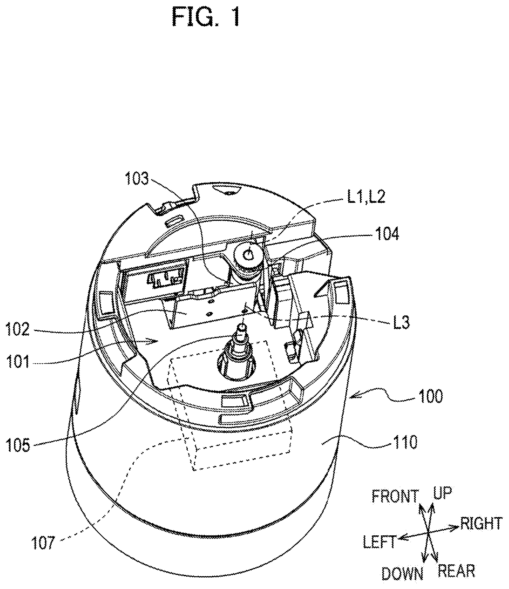
ART With a printing device that performs printing on a printing tape, cassettes that accommodates therein a printing tape are attached to and detached from a printing device body to replace and supply a printing tape. In one such cassette, a prior art discloses a configuration in which an ink ribbon and a printing tape are accommodated in a single case. DESCRIPTION Since the ink ribbon and the printing tape constitute a set in the cassette described above, combinations of colors of ink and types of the printing tape (e.g., color, size, material, etc.) are limited by the types of available cassettes. In view of the foregoing, it is an object of the present disclosure to provide an auxiliary tape cassette that can arbitrarily combine any auxiliary tape and printing tape. In order to attain the above and other object, the present disclosure provides an auxiliary tape cassette including: an auxiliary tape; a gear; and a case. The auxiliary tape is used for printing on a printing tape. The gear transmits a driving force from an outside. The case accommodates therein at least a part of the auxiliary tape and at least a part of the gear. The case has: a discharge opening; and a guide part. The discharge opening discharges the printing tape to an outside. The guide part guides the printing tape supplied from an outside of the case toward the discharge opening. In the above structure, since the printing tape supplied from the outside of the case can be guided toward the discharge opening using the guide part, any printing tape can be supplied into the case. As a result, any auxiliary tape and printing tape can be combined arbitrarily. Further, the positioning accuracy of the gear relative to a printing device body can be improved by providing the case that accommodates therein at least a part of the auxiliary tape and at least a part of the gear. is a schematic perspective view illustrating a printing device body. A and 2 B are schematic perspective views of a printing cassette. A and 3 B are schematic perspective views of a printing tape cassette of A . is a schematic exploded perspective view of the printing cassette of A . A and 5 B are schematic perspective views of an auxiliary tape cassette of A . A is a schematic perspective view of a printing cassette. B is a schematic perspective view illustrating a state where a printing tape roll is detached from the printing cassette of A . is a schematic exploded perspective view of the printing cassette of A . A and 8 B are schematic perspective views of a printing cassette. A and 9 B are schematic perspective views of a printing tape cassette of A . A and 10 B are schematic perspective views of an auxiliary tape cassette of A . is a schematic exploded perspective view of the auxiliary tape cassette of A . is a schematic exploded perspective view of an auxiliary tape cassette. is a schematic perspective view illustrating a state where a third case part is detached from the auxiliary tape cassette of . 1. First Embodiment [1-1. Configuration] A printing device body 100 illustrated in consists a printing device together with a printing cassette 10 illustrated in A and 2 B . This printing device is a device that performs printing on a tape-like printing medium. In the present embodiment, an axial direction of an output gear 21 will be referred to as an up-down direction, a direction orthogonal to the up-down direction in which the output gear 21 and a take-up spool 16 are arranged will be referred to as a front-rear direction, and a direction orthogonal to both the up-down direction and the front-rear direction will be referred to as a left-right direction. <Printing Device Body> As illustrated in , the printing device body 100 includes a cassette accommodation part 101 , a printing head 102 , a platen roller 103 , a platen gear 104 , a drive shaft 105 , a drive source 107 , and a housing 110 . (Cassette Accommodation Part) The cassette accommodation part 101 is a recess in which the printing cassette 10 is mounted. The cassette accommodation part 101 functions to position the printing cassette 10 . The cassette accommodation part 101 is provided in the housing 110 . (Printing Head) The printing head 102 is disposed inside the cassette accommodation part 101 . The printing head 102 has a plurality of heating elements whose heat generation is individually controlled. (Platen Roller) The platen roller 103 is disposed inside the cassette accommodation part 101 near the printing head 102 so as to oppose the printing head 102 . The platen roller 103 is pivotally movable in a direction toward or away from the printing head 102 . A rotational axis L 1 of the platen roller 103 is parallel to the up-down direction. (Platen Gear) The platen gear 104 is coupled to the platen roller 103 . In the present embodiment, a rotational axis L 2 of the platen gear 104 is arranged on the same line as the rotational axis L 1 of the platen roller 103 . The platen gear 104 is pivotally movable together with the platen roller 103 . (Drive Shaft) The drive shaft 105 is inserted into the take-up spool 16 and an input gear 22 in the printing cassette 10 . The drive shaft 105 rotates the take-up spool 16 and the input gear 22 . The drive shaft 105 is disposed inside the cassette accommodation part 101 . A rotational axis L 3 of the drive shaft 105 is parallel to the up-down direction. The drive shaft 105 is rotated about the rotational axis L 3 by the drive source 107 . (Drive Source) The drive source 107 drives the drive shaft 105 to rotate. A mechanism in which a motor and gears are combined, for example, can be used as the drive source 107 . <Printing Cassette> The printing cassette 10 illustrated in A and 2 B includes a printing medium (i.e., a printing tape 11 A). The printing cassette 10 is attachable to and detachable from the printing device body 100 . By replacing the printing cassette 10 , the printing medium can be replenished and the type of printing medium (e.g., the size, color, material, etc.) can be changed. The printing cassette 10 includes a printing tape cassette 30 , and an auxiliary tape cassette 40 . The printing cassette 10 is attached to the printing device body 100 while the printing tape cassette 30 and the auxiliary tape cassette 40 are coupled to each other. (Printing Tape Cassette) The printing tape cassette 30 illustrated in A and 3 B includes a printing tape case 35 that accommodates therein at least a part of the printing tape 11 A. As illustrated in , the printing tape cassette 30 also includes a printing tape roll 11 (an example of the second roll), a first supply spool 12 , and spacer films 13 A and 13 B. (Printing Tape Roll) The printing tape roll 11 is configured of the printing tape 11 A subjected to printing wound around the first supply spool 12 . Printing is performed on a surface of the printing tape 11 A by the printing head 102 in the printing device body 100 and an ink ribbon 14 A (an example of the auxiliary tape). The two spacer films 13 A and 13 B are disposed on respective outer sides of the printing tape roll 11 in the up-down direction so as to interpose the printing tape roll 11 therebetween. The spacer films 13 A and 13 B are disposed between the printing tape roll 11 and a first case part 31 and between the printing tape roll 11 and a second case part 32 , respectively. (First Supply Spool) The first supply spool 12 is rotatable about a rotational axis L 4 . The first supply spool 12 supplies the printing tape 11 A to the printing head 102 by rotating in accordance with conveyance of the printing tape 11 A by the platen roller 103 of the printing device body 100 . The rotational axis L 4 of the first supply spool 12 is parallel to the up-down direction and is coincident with a winding axis of the printing tape roll 11 . (Printing Tape Case) The printing tape case 35 has the first case part 31 , the second case part 32 , a first guide surface 35 A (see A and 3 B ), and a first discharge opening 35 B (see A and 3 B ). The first case part 31 constitutes an upper end portion of the printing tape case 35 . The second case part 32 constitutes a lower end portion of the printing tape case 35 . The second case part 32 is disposed below the first case part 31 and is coupled to the first case part 31 in the up-down direction. The printing tape roll 11 is disposed in a space enclosed by the first case part 31 and the second case part 32 . The first case part 31 has a first side wall 31 A, and a first notch 31 B. The second case part 32 has a second side wall 32 A, a second notch 32 B, and a first positioning part 32 C. Among outer surfaces of the printing tape case 35 , the first side wall 31 A and the second side wall 32 A constitute a side surface that circumferentially surrounds the printing tape roll 11 . The first notch 31 B is provided in a front portion of the first side wall 31 A. The second notch 32 B is provided in a front portion of the second side wall 32 A. The first notch 31 B and the second notch 32 B are coupled together to constitute the first discharge opening 35 B for the printing tape 11 A. As illustrated in A and 2 B , a part of the side surface of the printing tape case 35 constitutes the first guide surface 35 A, which guides the printing tape 11 A that has been discharged through the first discharge opening 35 B of the printing tape case 35 . The first discharge opening 35 B is provided in the side surface of the printing tape case 35 for discharging the printing tape 11 A out of the printing tape case 35 . The printing tape 11 A that has been discharged through the first discharge opening 35 B in a radial direction of the printing tape roll 11 is conveyed downward from the first discharge opening 35 B (i.e., toward the auxiliary tape cassette 40 ) while being wound around the first guide surface 35 A in a spiral shape having a central axis that is parallel to the up-down direction. As illustrated in A , the first positioning part 32 C is a hole provided in a first coupling surface 35 C of the printing tape case 35 . The first coupling surface 35 C is a surface that opposes and contacts the auxiliary tape cassette 40 positioned below the printing tape case 35 when the printing tape case 35 has been inserted into the cassette accommodation part 101 . The first positioning part 32 C positions the printing tape case 35 relative to the auxiliary tape cassette 40 . A second positioning part 41 E on the auxiliary tape cassette 40 is inserted into the first positioning part 32 C. Among the outer surfaces of the printing tape case 35 , the first coupling surface 35 C is a flat surface that crosses (specifically, that is orthogonal to) the up-down direction. The auxiliary tape cassette 40 can be arranged on the first coupling surface 35 C. (Auxiliary Tape Cassette) The auxiliary tape cassette 40 illustrated in A and 5 B is attachable to and detachable from the printing tape cassette 30 . The auxiliary tape cassette 40 includes an auxiliary tape case 45 (an example of the case) that accommodates therein at least a part of the ink ribbon 14 A and at least a part of a drive transmission unit 20 . The auxiliary tape cassette 40 in the present embodiment also serves as a gear cassette that accommodates therein gears. As illustrated in , the auxiliary tape cassette 40 includes an ink ribbon roll 14 (an example of the first roll and the auxiliary tape roll), a second supply spool 15 , the take-up spool 16 , a clutch spring holder 17 , and the drive transmission unit 20 . (Ink Ribbon Roll) The ink ribbon roll 14 is configured of the ink ribbon 14 A wound around the second supply spool 15 . The ink ribbon 14 A is used for printing on the printing tape 11 A. The ink ribbon 14 A is superimposed on the printing tape 11 A being conveyed at a head opening 42 B (an example of the exposure opening) and is used for printing by the printing head 102 . The ink ribbon 14 A that has been used for printing is taken up by the take-up spool 16 . Rotational resistance is applied to the ink ribbon roll 14 by a clutch spring (not illustrated) held in the clutch spring holder 17 . At least a part of the ink ribbon roll 14 is disposed in a position that is overlapped with the printing tape roll 11 in the up-down direction. (Second Supply Spool) The second supply spool 15 is rotatable about a rotational axis L 5 . The rotational axis L 5 of the second supply spool 15 is parallel to the rotational axis L 4 of the first supply spool 12 , i.e., is parallel to the up-down direction, and is coincident with a winding axis of the ink ribbon roll 14 . The second supply spool 15 supplies the ink ribbon 14 A to the head opening 42 B by rotating as the take-up spool 16 takes up the ink ribbon 14 A. (Take-up Spool) The take-up spool 16 is rotatable about a rotational axis L 6 . The rotational axis L 6 of the take-up spool 16 is parallel to the rotational axis L 5 of the second supply spool 15 . The take-up spool 16 is a cylindrical part that has a hollow part defined by an inner circumferential surface 16 A. Splines 16 B are provided on the inner circumferential surface 16 A of the take-up spool 16 . The drive shaft 105 of the printing device body 100 is coupled to the splines 16 B. The take-up spool 16 is rotated by the drive shaft 105 to take up the ink ribbon 14 A that has been used for printing. (Drive Transmission Unit) When a printing cassette 10 has been attached to the printing device body 100 , the drive transmission unit 20 transmits a driving force of the drive source 107 transmitted through the drive shaft 105 to the platen roller 103 and rotates the platen roller 103 at a rotational speed set for the respective printing cassettes 10 . The drive transmission unit 20 includes the output gear 21 , the input gear 22 , and an idle gear 23 . The drive transmission unit 20 is disposed further upward than the ink ribbon roll 14 (i.e., near the printing tape cassette 30 ). In other words, the output gear 21 and the input gear 22 are arranged in the auxiliary tape case 45 to be spaced apart from the ink ribbon roll 14 in the up-down direction. (Output Gear) The output gear 21 is an external gear provided for outputting a driving force used for conveying the printing tape 11 A to an outside. Specifically, the output gear 21 transmits the driving force from an outside to the platen gear 104 of the printing device body 100 . A rotational axis L 7 of the output gear 21 is parallel to the rotational axis L 5 of the second supply spool 15 . A part of the output gear 21 is exposed to a space that communicates with the head opening 42 B. The output gear 21 engages with the platen gear 104 at the space communicating with the head opening 42 B while the printing cassette 10 is attached to the printing device body 100 (i.e., while the auxiliary tape case 45 is accommodated in the cassette accommodation part 101 ). (Input Gear) The input gear 22 indirectly engages with the output gear 21 via the idle gear 23 and transmits a driving force to the output gear 21 . The input gear 22 has an external gear 22 A, and a spool 22 B. The spool 22 B is fixed to one side surface of the external gear 22 A. The spool 22 B is a cylindrical internal gear with splines provided on an inner circumferential surface thereof. The external gear 22 A is rotated integrally with the spool 22 B by the driving force of the drive source 107 inputted into the spool 22 B. A rotational axis L 8 of the input gear 22 (i.e., a rotational axis of the external gear 22 A and a rotational axis of the spool 22 B) is arranged on the same line as the rotational axis L 6 of the take-up spool 16 . At least a part of the input gear 22 is disposed at a position overlapped with the printing tape roll 11 in the up-down direction. The rotational axis L 8 of the input gear 22 is overlapped with the hollow part of the take-up spool 16 in the up-down direction. Also, a lower end portion of the spool 22 B in the input gear 22 is inserted into the hollow part of the take-up spool 16 from above. Therefore, the drive shaft 105 is simultaneously inserted into the take-up spool 16 and the input gear 22 in a state where the printing cassette 10 is attached to the printing device body 100 . As a result, the input gear 22 , although not directly coupled to the take-up spool 16 , is rotated together with the take-up spool 16 by the drive shaft 105 . (Idle Gear) The idle gear 23 is drivingly coupled to (i.e., engages with) the input gear 22 and the output gear 21 , and transmits a driving force inputted into the input gear 22 to the output gear 21 . Hence, the drive shaft 105 inputs a driving force into the output gear 21 indirectly via the input gear 22 and the idle gear 23 . The idle gear 23 is a stepped gear having an upstream gear 23 A engaging with the input gear 22 , and a downstream gear 23 B engaging with the output gear 21 . The upstream gear 23 A and the downstream gear 23 B are coaxially juxtaposed with each other. The downstream gear 23 B has a diameter smaller than the upstream gear 23 A. Further, the downstream gear 23 B is arranged closer to the printing tape cassette 30 than the upstream gear 23 A is to the printing tape cassette 30 in the up-down direction (i.e., above the downstream gear 23 B). The idle gear 23 transmits the driving force inputted into the input gear 22 to the output gear 21 after reducing a rotational speed of the driving force. That is, the drive transmission unit 20 includes a reduction mechanism whose reduction ratio is a transmission ratio obtained by dividing a rotational speed of the input gear 22 by a rotational speed of the output gear 21 . (Auxiliary Tape Case) The auxiliary tape case 45 has a third case part 41 , a fourth case part 42 , a fifth case part 43 , and a guide part 46 (see A ). The third case part 41 constitutes an upper end portion of the auxiliary tape case 45 . The fifth case part 43 constitutes a lower end portion of the auxiliary tape case 45 . The fourth case part 42 is arranged below the third case part 41 and above the fifth case part 43 , and is coupled to the third case part 41 and the fifth case part 43 in the up-down direction. The ink ribbon roll 14 , the second supply spool 15 , and the take-up spool 16 are disposed in a space enclosed by the fourth case part 42 and the fifth case part 43 . A part of the output gear 21 , the input gear 22 , and the idle gear 23 are disposed in a space enclosed by the third case part 41 and the fourth case part 42 . The third case part 41 has a third side wall 41 A, a first gear support part 41 B, a second gear support part 41 C, a third gear support part 41 D, and the second positioning part 41 E (see B ). Among outer surfaces of the auxiliary tape case 45 , the third side wall 41 A constitutes a side surface, which is continuous with the side surface of the printing tape case 35 . The first gear support part 41 B supports the output gear 21 such that the output gear 21 is rotatable. The second gear support part 41 C supports the input gear 22 such that the input gear 22 is rotatable. The third gear support part 41 D supports the idle gear 23 such that the idle gear 23 is rotatable. The second positioning part 41 E illustrated in B is provided on a second coupling surface 45 B. The second coupling surface 45 B opposes and contacts the printing tape cassette 30 positioned above the second coupling surface 45 B while the auxiliary tape case 45 is inserted in the cassette accommodation part 101 . Among the outer surfaces of the auxiliary tape case 45 , the second coupling surface 45 B is a flat surface that crosses (specifically, that is orthogonal to) the up-down direction and that is parallel to the first coupling surface 35 C of the printing tape case 35 . The printing tape cassette 30 can be arranged on the second coupling surface 45 B. The second positioning part 41 E is a cylindrical or columnar part that protrudes upward from the second coupling surface 45 B. When the auxiliary tape cassette 40 and the printing tape cassette 30 are coupled together, the auxiliary tape cassette 40 is positioned relative to the printing tape cassette 30 in the front-rear direction and the left-right direction by the second positioning part 41 E being inserted into the first positioning part 32 C of the printing tape case 35 . The fourth case part 42 illustrated in has a fourth side wall 42 A, the head opening 42 B, a second discharge opening 42 C (an example of the discharge opening), an inner guide wall 42 D, a first restricting part 42 E, and a ceiling wall 42 F. Among the outer surfaces of the auxiliary tape case 45 , the fourth side wall 42 A constitutes a side surface that circumferentially surrounds the ink ribbon roll 14 . The head opening 42 B is a cutout formed in a part of the fourth side wall 42 A. The head opening 42 B is a space in which the printing head 102 is placed in a state where the printing cassette 10 is attached to the printing device body 100 . In the head opening 42 B, printing is performed on the printing tape 11 A by the printing head 102 . The head opening 42 B is open in a lower portion of the auxiliary tape cassette 40 so that the printing head 102 can be inserted thereinto from below. The printing tape 11 A and the ink ribbon 14 A are passed over the head opening 42 B in the left-right direction. The printing tape 11 A is exposed in the head opening 42 B at a position upstream relative to the second discharge opening 42 C in a discharging direction of the printing tape 11 A. The second discharge opening 42 C discharges the printing tape 11 A on which printing has been performed to an outside of the printing cassette 10 . That is, the second discharge opening 42 C discharges the printing tape 11 A from an inside of the auxiliary tape case 45 to the outside therethrough. The printed printing tape 11 A is discharged to an outside of the printing device through the second discharge opening 42 C. The inner guide wall 42 D is a plate-like part having a front surface that guides the printing tape 11 A (i.e., contacts the printing tape 11 A from the rear) along the left-right direction inside the auxiliary tape case 45 . The inner guide wall 42 D constitutes a part of a second guide surface 45 A that guides the printing tape 11 A toward the second discharge opening 42 C. The inner guide wall 42 D is continuously provided from the fourth side wall 42 A. Additionally, the inner guide wall 42 D is disposed upstream of the head opening 42 B in the discharging direction of the printing tape 11 A and further frontward than the head opening 42 B. At least a part of the inner guide wall 42 D is disposed at the same position as the second discharge opening 42 C in the up-down direction. That is, at least a part of the inner guide wall 42 D is overlapped with the second discharge opening 42 C in a direction orthogonal to the up-down direction. The printing tape 11 A is conveyed on the inner guide wall 42 D in a direction orthogonal to the up-down direction (specifically, in the left-right direction). The first restricting part 42 E restricts movement of the printing tape 11 A in a width direction thereof when the printing tape 11 A is conveyed along the second guide surface 45 A configured by the inner guide wall 42 D. Specifically, the first restricting part 42 E is disposed above the inner guide wall 42 D and has a lower surface that is orthogonal to the up-down direction. The ceiling wall 42 F is disposed frontward of the inner guide wall 42 D to be spaced apart from the inner guide wall 42 D. The ceiling wall 42 F and the inner guide wall 42 D constitute therebetween a conveying path for the printing tape 11 A. The ceiling wall 42 F is connected to the first restricting part 42 E. An inner surface (i.e., a rear surface) of the ceiling wall 42 F constitutes a restricting surface that is arranged to oppose the inner guide wall 42 D. The fifth case part 43 has a fifth side wall 43 A, and a second restricting part 43 B. Together with the fourth side wall 42 A of the fourth case part 42 , the fifth side wall 43 A constitutes the side surface of the auxiliary tape case 45 that circumferentially surrounds the ink ribbon roll 14 . The second restricting part 43 B restricts movement of the printing tape 11 A in the width direction thereof in cooperation with the first restricting part 42 E when the printing tape 11 A is conveyed along the second guide surface 45 A. Specifically, the second restricting part 43 B is disposed below the inner guide wall 42 D of the fourth case part 42 and has an upper surface that is orthogonal to the up-down direction. The second restricting part 43 B opposes the first restricting part 42 E of the fourth case part 42 in the up-down direction. The inner guide wall 42 D, the ceiling wall 42 F, the first restricting part 42 E, and the second restricting part 43 B configure an arm part 45 C, as illustrated in B . The arm part 45 C has a space through which the printing tape 11 A passes when the printing tape 11 A is conveyed along the second guide surface 45 A of the auxiliary tape case 45 . The arm part 45 C constitutes a tunnel-like part that encompasses the printing tape 11 A in the width direction and a thickness direction thereof. An entrance for the printing tape 11 A in the arm part 45 C constitutes an insertion opening 45 F through which the printing tape 11 A supplied from the printing tape cassette 30 is inserted to the inside of the auxiliary tape case 45 . Within the arm part 45 C, the inner guide wall 42 D and the ceiling wall 42 F restrict movement of the printing tape 11 A in the front-rear direction (i.e., the thickness direction) and the first restricting part 42 E and the second restricting part 43 B restrict movement of the printing tape 11 A in the up-down direction (i.e., the width direction). The printing tape 11 A that has passed through the arm part 45 C is supplied to the head opening 42 B. As illustrated in A and 2 B , a part of the side surface of the auxiliary tape case 45 constitutes the second guide surface 45 A, which guides the printing tape 11 A supplied from an outside of the auxiliary tape case 45 (i.e., from the printing tape cassette 30 ) toward the second discharge opening 42 C. The printing tape 11 A guided by the first guide surface 35 A of the printing tape case 35 is further guided toward the second discharge opening 42 C by the second guide surface 45 A. The guide part 46 guides the printing tape 11 A supplied from the outside of the auxiliary tape case 45 toward the second discharge opening 42 C. The guide part 46 has the second guide surface 45 A, and the insertion opening 45 F. The insertion opening 45 F is provided in an insertion side surface 45 G (an example of the side surface) of the auxiliary tape case 45 . Among the outer surfaces of the auxiliary tape case 45 , the insertion side surface 45 G is a surface that crosses the left-right direction (specifically, is parallel to the up-down direction) and that is arranged at a position that is not overlapped with the ink ribbon roll 14 in the up-down direction (specifically, arranged frontward of the ink ribbon roll 14 ). The printing tape 11 A is inserted rightward through the insertion opening 45 F. <Conveyance and Printing of Printing Tape with Printing Device Body> When the printing cassette 10 is attached to the printing device body 100 , the printing tape 11 A is wrapped around the first guide surface 35 A of the printing tape case 35 and the second guide surface 45 A of the auxiliary tape case 45 to form a spiral portion 11 B. The spiral portion 11 B of the conveyed printing tape 11 A is wrapped across the side surface of the printing tape case 35 and the side surface of the auxiliary tape case 45 . Specifically, the spiral portion 11 B extends from the first discharge opening 35 B of the printing tape case 35 to the insertion opening 45 F. When the printing cassette 10 is attached to the printing device body 100 with the printing tape 11 A wrapped around the guide surfaces in this way, the printing head 102 is arranged in the head opening 42 B at a position overlapped with the printing tape 11 A and the ink ribbon 14 A in the front-rear direction. The printing tape 11 A is conveyed to the head opening 42 B by the platen roller 103 and is pressed against the printing head 102 through the ink ribbon 14 A by the platen roller 103 while the heating elements of the printing head 102 generate heat. As a result, some ink provided on a surface of the ink ribbon 14 A is transferred onto the printing tape 11 A, whereby characters, symbols, and the like are printed on the printing tape 11 A. The platen roller 103 conveys the printed printing tape 11 A from an inside of the printing cassette 10 toward the outside of the printing cassette 10 . The platen roller 103 is rotated by the platen gear 104 , which is engaged with the output gear 21 . The platen roller 103 and the platen gear 104 is pivotally movable between a position in which the platen roller 103 and the platen gear 104 are separated from the printing cassette 10 and a position in which the platen gear 104 is engaged with the output gear 21 . While the auxiliary tape case 45 of the printing cassette 10 is inserted into the cassette accommodation part 101 , the drive shaft 105 is engaged with the input gear 22 and the platen gear 104 is engaged with the output gear 21 . Specifically, while the drive shaft 105 is inserted into the take-up spool 16 and the input gear 22 of the printing cassette 10 , the platen gear 104 is engaged with the output gear 21 by pivotal movement of the platen roller 103 and the platen gear 104 toward the head opening 42 B of the printing cassette 10 . With the printing cassette 10 in its attached state, the output gear 21 is rotated when the drive shaft 105 rotates the input gear 22 . Further, the platen gear 104 is rotated by the rotation of the output gear 21 , and the platen roller 103 is rotated by the rotation of the platen gear 104 . [1-2. Effects] The following effects can be obtained according to the embodiment described above. ( 1 a ) With the auxiliary tape cassette 40 , any arbitrary printing tape 11 A can be supplied into the auxiliary tape case 45 since the printing tape 11 A supplied from an outside is guided to the second discharge opening 42 C by the guide part 46 . As a result, any ink ribbon 14 A and printing tape 11 A can be arbitrarily combined. Further, by providing the auxiliary tape case 45 that accommodates therein the ink ribbon 14 A and the drive transmission unit 20 , the output gear 21 can be positioned relative to the printing device body 100 with greater accuracy. ( 1 b ) The insertion opening 45 F of the guide part 46 allows the printing tape 11 A to be inserted into the auxiliary tape case 45 . This configuration can both protect the printing tape 11 A while ensuring stable conveyance of the printing tape 11 A. ( 1 c ) By arranging the insertion opening 45 F in the insertion side surface 45 G of the auxiliary tape case 45 , a part of the path for the printing tape 11 A (i.e., the second guide surface 45 A) can be provided on the outer side (i.e., on the side surface) of the auxiliary tape case 45 . As a result, the printing tape 11 A can be introduced into the auxiliary tape case 45 relatively easily while a size of the auxiliary tape cassette 40 can be reduced. 2. Second Embodiment [2-1. Configuration] A printing cassette 210 illustrated in A and 6 B is attached to the printing device body 100 of in place of the printing cassette 10 according to the first embodiment. The printing cassette 210 includes the printing tape roll 11 , the first supply spool 12 , and an auxiliary tape cassette 240 . (Auxiliary Tape Cassette) The auxiliary tape cassette 240 includes an auxiliary tape case 245 that accommodates therein the ink ribbon roll 14 , the drive transmission unit 20 , and the like the same as those in the first embodiment. The auxiliary tape case 245 includes a third case part 241 , a fourth case part 242 , and a fifth case part 243 . The fourth case part 242 and the fifth case part 243 are identical to the respective fourth case part 42 and the fifth case part 43 in the first embodiment. As illustrated in , the fourth case part 242 and the fifth case part 243 constitute an auxiliary tape accommodation part 51 that accommodates therein the ink ribbon roll 14 . The third case part 241 and the fourth case part 242 constitute a gear accommodation part 52 that accommodates therein the drive transmission unit 20 . The third case part 241 supports the printing tape roll 11 . The third case part 241 includes a partitioning wall 241 A, a shaft part 241 B, and a side wall 241 C. The partitioning wall 241 A covers the drive transmission unit 20 from above. The partitioning wall 241 A extends in the front-rear direction and the left-right direction. The shaft part 241 B is a columnar or cylindrical part that protrudes upward from an upper surface of the partitioning wall 241 A. The shaft part 241 B can support the printing tape roll 11 . The shaft part 241 B is inserted into hollow parts of the printing tape roll 11 and the first supply spool 12 . The side wall 241 C protrudes upward from an edge of the partitioning wall 241 A. The side wall 241 C is arranged to surround at least a part of the shaft part 241 B from outward in a radial direction thereof. The printing tape roll 11 is inserted between the shaft part 241 B and the side wall 241 C. That is, the side wall 241 C constitutes a printing tape accommodation part 53 that can accommodate therein the printing tape roll 11 . Note that the printing tape accommodation part 53 may have a cover that, in cooperation with the partitioning wall 241 A, interposes the printing tape roll 11 therebetween in the up-down direction. The cover is configured to be movable between an open position in which the printing tape roll 11 can be placed in the printing tape accommodation part 53 , and a closed position in which detachment of the printing tape roll 11 is prevented. The printing tape accommodation part 53 , the gear accommodation part 52 , and the auxiliary tape accommodation part 51 are arranged in the up-down direction in the order of the printing tape accommodation part 53 , the gear accommodation part 52 , and the auxiliary tape accommodation part 51 . [2-2. Effects] The following effects can be obtained according to the embodiment described above. ( 2 a ) By virtue of each of the shaft part 241 B and the auxiliary tape accommodation part 51 , the printing tape roll 11 can be attached to the auxiliary tape cassette 240 while the printing tape roll 11 is positioned relative to the auxiliary tape cassette 240 . ( 2 b ) Since the gear accommodation part 52 is arranged between the printing tape accommodation part 53 and the auxiliary tape accommodation part 51 in the up-down direction, positioning accuracy of the output gear 21 relative to the printing device body 100 can be improved. 3. Third Embodiment [3-1. Configuration] A printing cassette 410 illustrated in A and 8 B is attached to the printing device body 100 of in place of the printing cassette 10 according to the first embodiment. The printing cassette 410 includes a printing tape cassette 430 , and an auxiliary tape cassette 440 . Note that A illustrates a state in which a first case part 431 of the printing tape cassette 430 has been removed. B illustrates a state in which a third case part 441 of the auxiliary tape cassette 440 has been removed. (Printing Tape Cassette) The printing tape cassette 430 illustrated in A and 9 B has a printing tape case 435 that accommodates therein the printing tape 11 A. Parts accommodated in the printing tape case 435 are the same as those in the printing cassette 10 of the first embodiment. The printing tape case 435 has the first case part 431 , a second case part 432 , a first guide surface 435 A, and a first discharge opening 435 B. The first case part 431 constitutes an upper end portion of the printing tape case 435 . The second case part 432 is coupled to a lower portion the first case part 431 and constitutes a lower end portion of the printing tape case 435 . The second case part 432 has the first positioning part 32 C provided on the first coupling surface 35 C, similar to the first embodiment. Further, the second case part 432 has an inner wall 432 A constituting the first guide surface 435 A, and an opening constituting the first discharge opening 435 B. The inner wall 432 A surrounds the printing tape roll 11 from outward in a radial direction. The first discharge opening 435 B is provided in the first coupling surface 35 C. The first discharge opening 435 B discharges the printing tape 11 A to an outside of the printing tape case 435 in a direction crossing the first coupling surface 35 C (i.e., the up-down direction). As illustrated in A , the first guide surface 435 A guides the printing tape 11 A drawn off the printing tape roll 11 toward the first discharge opening 435 B. The printing tape 11 A is wrapped around the first guide surface 435 A from outward in the radial direction of the printing tape roll 11 while forming the spiral portion 11 B. (Auxiliary Tape Cassette) The auxiliary tape cassette 440 illustrated in A and 10 B has an auxiliary tape case 445 that accommodates therein the ink ribbon 14 A and the drive transmission unit 20 . Parts accommodated in the auxiliary tape case 445 are the same as those in the printing cassette 10 of the first embodiment. The auxiliary tape case 445 has the third case part 441 , a fourth case part 442 , a fifth case part 443 , a guide part 446 , and a guide opening 445 E. As illustrated in , the fourth case part 442 and the fifth case part 443 constitute an auxiliary tape accommodation part 451 that accommodates therein the ink ribbon roll 14 . The third case part 441 and the fourth case part 442 constitute a gear accommodation part 452 that accommodates therein the drive transmission unit 20 . The gear accommodation part 452 is arranged to be overlapped with at least a part of the auxiliary tape accommodation part 451 in the up-down direction. The third case part 441 constitutes an upper surface of the auxiliary tape case 445 (i.e., a second coupling surface 445 B). The fifth case part 443 constitutes a lower end portion of the auxiliary tape case 445 . The fourth case part 442 is coupled to an upper portion of the fifth case part 443 . As illustrated in B , the third case part 441 has the second positioning part 41 E the same as that in the first embodiment. Also, the third case part 441 supports the drive transmission unit 20 . The third case part 441 is fitted inside an outer wall 442 A of the fourth case part 442 so as to close off an interior space of the fourth case part 442 from above. The fourth case part 442 illustrated in has the head opening 42 B, the second discharge opening 42 C, the inner guide wall 42 D, the first restricting part 42 E, and the ceiling wall 42 F the same as those described in the first embodiment. The fourth case part 442 also has the outer wall 442 A, and an inner wall 442 B. The inner wall 442 B surrounds the ink ribbon roll 14 , the second supply spool 15 , and the take-up spool 16 from outward in a radial direction of the ink ribbon roll 14 . A part of an outer surface of the inner wall 442 B constitutes a second guide surface 445 A. The outer wall 442 A surrounds the inner wall 442 B from outward. As illustrated in B , an insertion opening 445 D is formed at an upper end portion of the auxiliary tape case 445 by the third case part 441 and the fourth case part 442 . The insertion opening 445 D is in communication with a space between the outer wall 442 A and the inner wall 442 B. The insertion opening 445 D is provided in the second coupling surface 445 B (an example of the first outer surface) that is coupled with the printing tape cassette 430 . The second coupling surface 445 B crosses the up-down direction (specifically, is orthogonal to the up-down direction) and is arranged to be offset from the ink ribbon roll 14 in the up-down direction (specifically, above the ink ribbon roll 14 ). The insertion opening 445 D is offset from the head opening 42 B when viewed from the up-down direction. That is, the insertion opening 445 D is not overlapped with the head opening 42 B in the up-down direction. Further, the gear accommodation part 452 is arranged to be offset from the insertion opening 445 D when viewed in the up-down direction. Accordingly, the printing tape 11 A is inserted into the auxiliary tape accommodation part 451 after moving past an outside of the gear accommodation part 452 . The printing tape 11 A that has been discharged through the first discharge opening 435 B of the printing tape case 435 is conveyed into the auxiliary tape case 445 through the insertion opening 445 D. As illustrated in B , the printing tape 11 A that has been fed into the auxiliary tape case 445 is wrapped around the second guide surface 445 A from outward in the radial direction of the ink ribbon roll 14 while forming the spiral portion 11 B. The guide part 446 guides the printing tape 11 A supplied from the outside of the auxiliary tape case 445 toward the second discharge opening 42 C. The guide part 446 includes the second guide surface 445 A, and the insertion opening 445 D. The fifth case part 443 illustrated in has the second restricting part 43 B the same as that in the first embodiment. The fifth case part 443 also has an opening constituting the guide opening 445 E. The guide opening 445 E is provided in a bottom surface 445 C (an example of the second outer surface). Together with the second coupling surface 445 B, the bottom surface 445 C interposes therebetween the ink ribbon roll 14 in the up-down direction in the auxiliary tape case 445 . The guide opening 445 E is in communication with the space between the outer wall 442 A and the inner wall 442 B of the fourth case part 442 . Further, at least a part of the guide opening 445 E opposes the insertion opening 445 D. Further, the guide opening 445 E extends along the second guide surface 445 A to a position overlapped with the arm part 45 C (i.e., the inner guide wall 42 D) so as to be overlapped with the conveying path of the printing tape 11 A in the fourth case part 442 in the up-down direction. Therefore, the printing tape 11 A inserted into the auxiliary tape case 445 through the insertion opening 445 D can be placed on the conveying path in the auxiliary tape case 445 while being drawn downward inside the auxiliary tape case 445 through the guide opening 445 E. Note that the guide opening 445 E is not overlapped with the entire ink ribbon roll 14 in the up-down direction. That is, the guide opening 445 E is formed in a shape that does not allow the ink ribbon roll 14 to pass downward through the fifth case part 443 and fall out of the auxiliary tape case 445 . Modification of Third Embodiment The auxiliary tape case 445 in the present embodiment may have a third case part 541 illustrated in in place of the third case part 441 . The third case part 541 has an outer wall 541 A, and an inner wall 541 B. The inner wall 541 B surrounds the drive transmission unit 20 in directions orthogonal to the up-down direction. A part of an outer surface of the inner wall 541 B constitutes the second guide surface 445 A. The outer wall 541 A surrounds the inner wall 541 B from outward. A space between the outer wall 541 A and the inner wall 541 B is in communication with the space between the outer wall 442 A and the inner wall 442 B of the fourth case part 442 . An upper end portion of the outer wall 541 A and an upper end portion of the inner wall 541 B constitute the insertion opening 445 D provided in the second coupling surface 445 B of the auxiliary tape case 445 . In other words, the gear accommodation part 452 has the second coupling surface 445 B and the insertion opening 445 D. As illustrated in , the auxiliary tape accommodation part 451 also has a communication opening 442 C. The communication opening 442 C is configured by an upper end portion of the outer wall 442 A and an upper end portion of the inner wall 442 B of the fourth case part 442 . The communication opening 442 C provides communication between the gear accommodation part 452 and the auxiliary tape accommodation part 451 . The printing tape 11 A that has been inserted into the gear accommodation part 452 through the insertion opening 445 D subsequently enters the auxiliary tape accommodation part 451 through the communication opening 442 C. [3-2. Effects] The following effects can be obtained according to the embodiment described above. ( 3 a ) By providing the insertion opening 445 D in the second coupling surface 445 B, the path for the printing tape 11 A (the second guide surface 445 A) is arranged inside the auxiliary tape cassette 440 when viewed along the up-down direction, thereby enabling the auxiliary tape cassette 440 to be made smaller. ( 3 b ) By arranging the gear accommodation part 452 to be offset from the auxiliary tape accommodation part 451 when viewed in the up-down direction or providing the communication opening 442 C in the auxiliary tape accommodation part 451 , the printing tape 11 A can be guided across the gear accommodation part 452 to the second discharge opening 42 C. ( 3 c ) The guide opening 445 E enables the printing tape 11 A to be placed on the guide part 446 in the auxiliary tape case 445 while being pulled out of the printing tape cassette 430 . 4. Other Embodiments While the invention has been described in conjunction with various example structures outlined above and illustrated in the figures, various alternatives, modifications, variations, improvements, and/or substantial equivalents, whether known or that may be presently unforeseen, may become apparent to those having at least ordinary skill in the art. Accordingly, the example embodiments of the disclosure, as set forth above, are intended to be illustrative of the invention, and not limiting the invention. Various changes may be made without departing from the spirit and scope of the disclosure. Therefore, the disclosure is intended to embrace all known or later developed alternatives, modifications, variations, improvements, and/or substantial equivalents. Some specific examples of potential alternatives, modifications, or variations in the described invention are provided below: ( 4 a ) The printing device in the above embodiments is not limited to a device that performs printing using an ink ribbon. In place of the printing tape, the printing device may use a strip of heat-sensitive paper. In this case, the auxiliary tape may be a laminated tape, for example. ( 4 b ) In the auxiliary tape cassette of the embodiments described above, the guide part need not have an insertion opening. That is, the guide part may guide the printing tape using only the outer surface of the auxiliary tape case. ( 4 c ) The auxiliary tape cassette of the third embodiment may include a shaft part and an auxiliary tape accommodation part those identical to the auxiliary tape cassette of the second embodiment. Further, one of the shaft part and the auxiliary tape accommodation part may be omitted from the auxiliary tape cassette of the second embodiment. ( 4 d ) Functions possessed by a single component in the embodiments described above may be distributed among a plurality of components, and functions possessed by a plurality of components may be integrated into a single component. Additionally, a part of the structures in the embodiments described above may be omitted. Further, at least a part of the structures in the embodiments described above may be added to or used in place of structures in other embodiments. All aspects included in the technical concepts identified from descriptions in the claims are embodiments of the present disclosure.
Figures (13)
Citations
This patent cites (100)
- US3672603
- US3804227
- US3823808
- US3948382
- US4034935
- US4252450
- US4351619
- US4397574
- US4402619
- US4490059
- US4499513
- US4538931
- US4565128
- US4598780
- US4668961
- US4832514
- US4856921
- US5099378
- US5145268
- US5325114
- US5402954
- US5435657
- US5472286
- US5619244
- US5645360
- US5917532
- US5959652
- US6511238
- US2007/0172286
- US2008/0084494
- US2010/0247208
- US2010/0247212
- US2011/0143073
- US2017/0282622
- US2020/0207107
- US2022/0016915
- US2022/0219472
- US2023/0219357
- US2023/0294431
- US2023/0356537
- US102092201
- US301959415
- US103273748
- US107264080
- US114502386
- US116194302
- US116234704
- US116802060
- US0414544
- US4023451
- US2016411
- USS50-36734
- USS54-111914
- USS59-6460
- USS59-95180
- USS60-8072
- USS60-9657
- USS60-36255
- USS60-038760
- USS60-46254
- USS60-48456
- USS60-188821
- USS60-224571
- USS61-154877
- USS62-103179
- USS63-156762
- USH02-6173
- USH02-9562
- USH02-11379
- USH02-11380
- USH02-37568
- USH03-97181
- USH03-284973
- USH04-152176
- USH05-41834
- USH05-53956
- USH06-183117
- USH07-9745
- USH07-32710
- US3015367
- USH07-276755
- USH07-276757
- USH08-183204
- USH08-183232
- US2000-103149
- US2001-047713
- US2002-211092
- US2005-280060
- US2007-502221
- US2008-261968
- US2009-196804
- US2010-234772
- US2011-148167
- US2011-150007
- US2014-170142
- US2017177709
- US2020-104324
- US2020-104510
- US2020168723
- US2005/018944