Abstract
A cassette holder holds a cassette for medical use. It includes a cassette receiving portion that includes a bottom surface to which a lower surface of the cassette is brought into contact when the cassette is set, and a plate-shaped portion that is provided in the cassette receiving portion, has a substantially plate-like shape, and extends substantially parallel to the bottom surface, and a protrusion inside of which is hollow, the protrusion being provided to the bottom surface to protrude downward. The bottom surface and the protrusion are provided with a plurality of through holes.
Claims (12)
1 . A cassette holder configured to hold a cassette for medical use, the cassette holder comprising: a cassette receiving portion in a state that a cassette is inserted and positioned in the cassette receiving portion; a plate-shaped portion that extends from a side wall of the cassette receiving portion; and a protrusion having a plate shape and a hollow interior, the protrusion being configured to project downward from a bottom surface of the cassette receiving portion, wherein the bottom surface and the protrusion are provided with a plurality of through holes, the cassette receiving portion is provided with a first slit and a second slit, the first slit and the second slit are collinearly aligned on the bottom surface of the cassette receiving portion, and the cassette receiving portion is foldable along the first slit and a second slit in an intermediate section of the cassette receiving portion.
Show 11 dependent claims
2 . The cassette holder according to claim 1 , wherein the cassette receiving portion has a rectangular shape aligned along a direction in which the first and second slits are collinearly aligned, the plate-shaped portion is provided to one of two short sides of the cassette receiving portions, and the first slit and the second slit are parallel to the short side to which the plate-shaped portion is provided.
3 . The cassette holder according to claim 1 , wherein the first slit and the second slit are provided in the cassette receiving portion and the protrusion, the cassette receiving portion includes a rib that protrudes upward from the bottom surface of the cassette receiving portion, and comes into contact with a peripheral edge of the cassette in a state that the cassette is inserted and positioned in the cassette receiving portion, and a height of the first slit and the second slit is equal to or more than half of a vertical distance between a distal end of the rib and a distal end of the protrusion.
4 . The cassette holder according to claim 1 , wherein the cassette receiving portion has a rectangular shape aligned along a direction in which the first and second slits are collinearly aligned, the plate-shaped portion is provided to one of two short sides of the cassette receiving portion, the plate-shaped portion includes a first side and a second side along a first direction that is parallel to a long side of the cassette receiving portion, the first side and the second side are respectively provided with a first projection and a second projection that are a pair of projections protruding outward along a direction in which the first and second slits are collinearly aligned, and a distal end of each of the first projection and the second projection is configured to be movable in a second direction orthogonal to the first direction.
5 . The cassette holder according to claim 4 , wherein the first projection and the second projection each include an arm portion that has an elongated plate shape and has a base end side provided in vicinity of the cassette receiving portion to be in a cantilever form, and the arm portion is elastically deformable.
6 . The cassette holder according to claim 1 , wherein the cassette receiving portion has a rectangular shape aligned along a direction in which the first and second slits are collinearly aligned, the plate-shaped portion is provided to one of two short sides of the cassette receiving portion, the plate-shaped portion includes a first side and a second side along a first direction that is parallel to a long side of the cassette receiving portion, and the first side and the second side are respectively provided with a first projection and a second projection that are a pair of projections protruding outward along a direction in which the first and second slits are collinearly aligned.
7 . The cassette holder according to claim 6 , wherein the first side and the second side are respectively provided with a third projection and a fourth projection that are a pair of projections protruding outward along a direction in which the first and second slits are collinearly aligned, a distal end of each of the third projection and the fourth projection is configured to be movable in a second direction orthogonal to the first direction, and the third projection and the fourth projection are provided between the cassette receiving portion and the first projection and the second projection.
8 . The cassette holder according to claim 7 , wherein the third projection and the fourth projection each include an arm portion that has an elongated plate shape and has a base end side provided in vicinity of the cassette receiving portion to be in a cantilever form, and the arm portion is elastically deformable.
9 . The cassette holder according to claim 7 , wherein the third projection and the fourth projection each have a hook shape, and each include an arm portion of a cantilever form that protrudes toward the cassette receiving portion from a corresponding one of the first projection and the second projection and has an elongated plate shape extending parallel to the first side and the second side, and a protruding portion that has an elongated plate shape, is provided at a distal end of the arm portion, and protrudes in a direction away from the plate-shaped portion, and the protruding portion includes a connection portion having one end provided to the arm portion, and an arc portion that has an arc shape and is provided on side of the connection portion opposite to the arm portion, and has center located closer to the plate-shaped portion than the protruding portion is.
10 . The cassette holder according to claim 8 , wherein the third projection and the fourth projection have distal end portions provided on ends not provided to the plate-shaped portion, and the distal end portions are inclined to have portions closer to the first projection and the second projection being closer to the plate-shaped portion.
11 . The cassette holder according to claim 9 , wherein the protruding portion has a flat surface portion orthogonal to a plane including the plate-shaped portion, and the flat surface portion is provided to an end of the arc portion on side opposite to the connection portion, and is inclined with respect to the first side and the second side along a direction in which the first and second slits are collinearly aligned.
12 . The cassette holder according to claim 11 , wherein the flat surface portion of the third projection is inclined with respect to the first side to have a portion closer to the first projection being closer to the first side, and the flat surface portion of the fourth projection is inclined with respect to the second side to have a portion closer to the second projection being closer to the second side.
Full Description
Show full text →
CROSS-REFERENCE TO RELATED APPLICATIONS
This application is a continuation application of International Patent Application No. PCT/JP2021/035880 filed on Sep. 29, 2021, which claims priority to Japanese Patent Application No. 2020-165304 filed on Sep. 30, 2020, the entire contents of which are incorporated by reference.
TECHNICAL FIELD
The present invention relates to a cassette holder.
BACKGROUND
ART Patent Literature 1 discloses a medical test cassette including a cassette body, a lid body, and a shielding plate. The cassette body is a rectangular container opened upward and has a bottom portion provided with multiple through holes. The lid body has multiple through holes and is attached to an upper portion of the cassette body. The shielding plate is a plate-shaped member having an upper surface provided with multiple protrusions that can be fitted into the through holes formed in the bottom portion of the cassette body. CITATION LIST Patent Literature Patent Literature 1: JP 2013-246076 A According to the invention described in Patent Literature 1, the cassette is immersed in chemical liquid together with a specimen sealed in the cassette with the lid body attached to the cassette body. In this process, the cassette body and the lid body need to be reliably fixed so that the lid body does not detach from the cassette body. However, according to the invention described in Patent Literature 1, when taking out an embedded block, the lid body needs to be detached from the cassette body after paraffin solidification, meaning that an operation of taking out the embedded block is not easy and is cumbersome. Furthermore, the invention described in Patent Literature 1 is premised on the chemical liquid treatment in which a cassette (that is, a specimen in the cassette) is manually immersed in the chemical liquid, meaning that a person needs to touch and take out the cassette immersed in the chemical liquid from the chemical liquid, and this is an insufficient procedure. Thus, with the invention described in Patent Literature 1, an embedded block is prepared with a low workability.
SUMMARY
OF INVENTION One or more embodiments of the present invention provide a cassette holder with which an embedded block is prepared with high workability. For example, a cassette holder according to one or more embodiments of the present invention to achieve the object described above is configured to hold a cassette for medical use, the cassette holder and includes: a cassette receiving portion to which the cassette is set, the cassette receiving portion including a bottom surface to which a lower surface of the cassette is brought into contact when the cassette is set; a plate-shaped portion that is provided in the cassette receiving portion, has a substantially plate-like shape, and extends substantially parallel to the bottom surface; and a protrusion inside of which is hollow, the protrusion being provided to the bottom surface to protrude downward, wherein the bottom surface and the protrusion are provided with a plurality of through holes. According to the cassette holder of one or more embodiments of the present invention, the plate-shaped portion having a plate shape extends substantially parallel to the bottom surface of the cassette receiving portion. With this configuration, the plate-shaped portion may be gripped when immersing the cassette set to the cassette receiving portion in chemical liquid, meaning that the cassette immersed in the chemical liquid needs not to be touched. Thus, the work can be safely and efficiently can be performed. Thus, the embedded block is prepared with excellent workability. The cassette receiving portion may be provided with a first slit and a second slit, and the first slit and the second slit may be collinearly arranged in plan view. Thus, the embedded block can be easily taken out from the inside of the cassette holder, with the cassette holder easily folded along the slits. Thus, the embedded block can be efficiently prepared. The cassette receiving portion may have a rectangular shape in plan view, the plate-shaped portion may be provided to one of two short sides of the cassette receiving portions, and the first slit and the second slit may be substantially parallel to the short side. Thus, the cassette holder can be easily folded along the first slit and the second slit. The first slit and the second slit may be provided in the cassette receiving portion and the protrusion, the cassette receiving portion may include a rib that protrudes upward from the bottom surface, and come into contact with a peripheral edge of the cassette when the cassette is set, and in side view, a height of the first slit and the second slit may be equal to or more than half of a distance between a distal end of the rib and a distal end of the protrusion. Thus, the cassette holder can be folded along the first slit and the second slit with a small amount of force. The cassette receiving portion may have a rectangular shape in plan view, the plate-shaped portion may be provided to one of two short sides of the cassette receiving portion, the plate-shaped portion may include a first side and a second side along a first direction that is substantially parallel to the cassette receiving portion, and the first side and the second side may be respectively provided with a first projection and a second projection that are a pair of projections protruding outward in plan view. With this configuration, when the cassette set to the cassette receiving portion is immersed in the chemical liquid with the plate-shaped portion gripped, the first projection and the second projection are caught on an opening portion of a bottle body of a chemical liquid bottle or a paraffin-filled bottle, so that the cassette holder does not fall into the chemical liquid bottle. Thus, the cassette can be easily taken out from the chemical liquid with the plate-shaped portion gripped, whereby excellent workability is achieved. The cassette receiving portion may have a rectangular shape in plan view, the plate-shaped portion may be provided to one of two short sides of the cassette receiving portion, the plate-shaped portion may include a first side and a second side along a first direction that is substantially parallel to a long side of the cassette receiving portion, the first side and the second side may be respectively provided with a first projection and a second projection that are a pair of projections protruding outward in plan view, and a distal end of each of the first projection and the second projection may be configured to be movable in a second direction substantially orthogonal to the first direction. With this configuration, when the cassette set to the cassette receiving portion is immersed in the chemical liquid with the plate-shaped portion gripped, the first projection and the second projection are caught on the opening portion of the bottle body of the chemical liquid bottle or the paraffin-filled bottle, so that the cassette holder does not fall into the chemical liquid bottle. Thus, the cassette can be easily taken out from the chemical liquid with the plate-shaped portion gripped, whereby excellent workability is achieved. The first side and the second side may be respectively provided with a third projection and a fourth projection that are a pair of projections protruding outward in plan view, a distal end of each of the third projection and the fourth projection may be configured to be movable in a second direction substantially orthogonal to the first direction, and the third projection and the fourth projection may be provided between the cassette receiving portion and the first projection and the second projection. Thus, the third projection and the fourth projection come into contact with the inner circumference surface of the bottle body. Thus, the cassette holder can be prevented from rotating in the bottle body. The third projection and the fourth projection may include a flat surface portion that is substantially parallel to the first side and the second side, and is substantially orthogonal to a plane including the plate-shaped portion. With this configuration, the flat surface portion presses the inner circumference surface of the bottle body. Thus, the cassette holder can be fixed to the bottle body with the cassette holder inserted in the bottle body prevented from rotating. The third projection and the fourth projection may each include an arm portion that has an elongated plate shape and has a base end side provided in vicinity of the cassette receiving portion to be in a cantilever form, and the arm portion may be elastically deformable. With this configuration, the third projection and the fourth projection can have a simple shape. The third projection and the fourth projection may each have a hook shape, and each include an arm portion of a cantilever form that protrudes toward the cassette receiving portion from a corresponding one of the first projection and the second projection and has an elongated plate shape extending substantially parallel to the first side and the second side, and a protruding portion that has an elongated plate shape, is provided at a distal end of the arm portion, and protrudes in a direction away from the plate-shaped portion, and the protruding portion may include a connection portion having one end provided to the arm portion, and an arc portion that has an arc shape and is provided on side of the connection portion opposite to the arm portion, and has center located closer to the plate-shaped portion than the protruding portion is. With this configuration, the arm portion extends substantially parallel to the first side and the second side, the direction of the force applied to the flat surface portion substantially coincides with the deformation direction of the arm portion, whereby the flat surface portion easily moves. Furthermore, the third projection and the fourth projection (the arm portion and the protruding portion) have long total lengths, and thus the third projection and the fourth projection can be elastically deformed by a small amount of force. The third projection and the fourth projection may have distal end portions provided on ends not provided to the plate-shaped portion, and the distal end portions may be inclined to have portions closer to the first projection and the second projection being closer to the plate-shaped portion. With this configuration, even when a projection due to burr or the like is formed in the opening portion of the bottle body into which the cassette holder is inserted, the third projection and the fourth projection would not get caught, whereby the cassette holder can be easily inserted in and taken out from the bottle. The protruding portion may have a flat surface portion substantially orthogonal to a plane including the plate-shaped portion, and the flat surface portion may be provided to an end of the arc portion on side opposite to the connection portion, and is inclined with respect to the first side and the second side in plan view. When the flat surface portion is inclined to have a portion closer to the first projection and the second projection being farther from the first side and the second side, the flat surface portion can more strongly press the inner circumference surface of the tubular bottle body. When the flat surface portion is inclined to have a portion closer to the first projection and the second projection being closer to the first side and the second side, the flat surface portion moves to be substantially parallel to the first side and the second side with the third projection and the fourth projection deformed, whereby the inner circumference surface of the bottle body can be pressed by the entire flat surface portion. The flat surface portion of the third projection may be inclined with respect to the first side to have a portion closer to the first projection being closer to the first side, and the flat surface portion of the fourth projection may be inclined with respect to the second side to have a portion closer to the second projection being closer to the second side. Thus, when the flat surface portion is inclined to have a portion closer to the first projection and the second projection being closer to the first side and the second side, the third projection and the fourth projection are deformed while pressing the inner circumference surface of the bottle body by the arc portion. Thus, the cassette holder is inserted in and taken out from the bottle body without imposing excessive force onto the third projection and the fourth projection, whereby the cassette holder is inserted and taken out smoothly, and the third projection and the fourth projection are prevented from being damaged. One or more embodiments of the present invention can provide a cassette holder with which an embedded block can be prepared with high workability.
BRIEF DESCRIPTION OF DRAWINGS
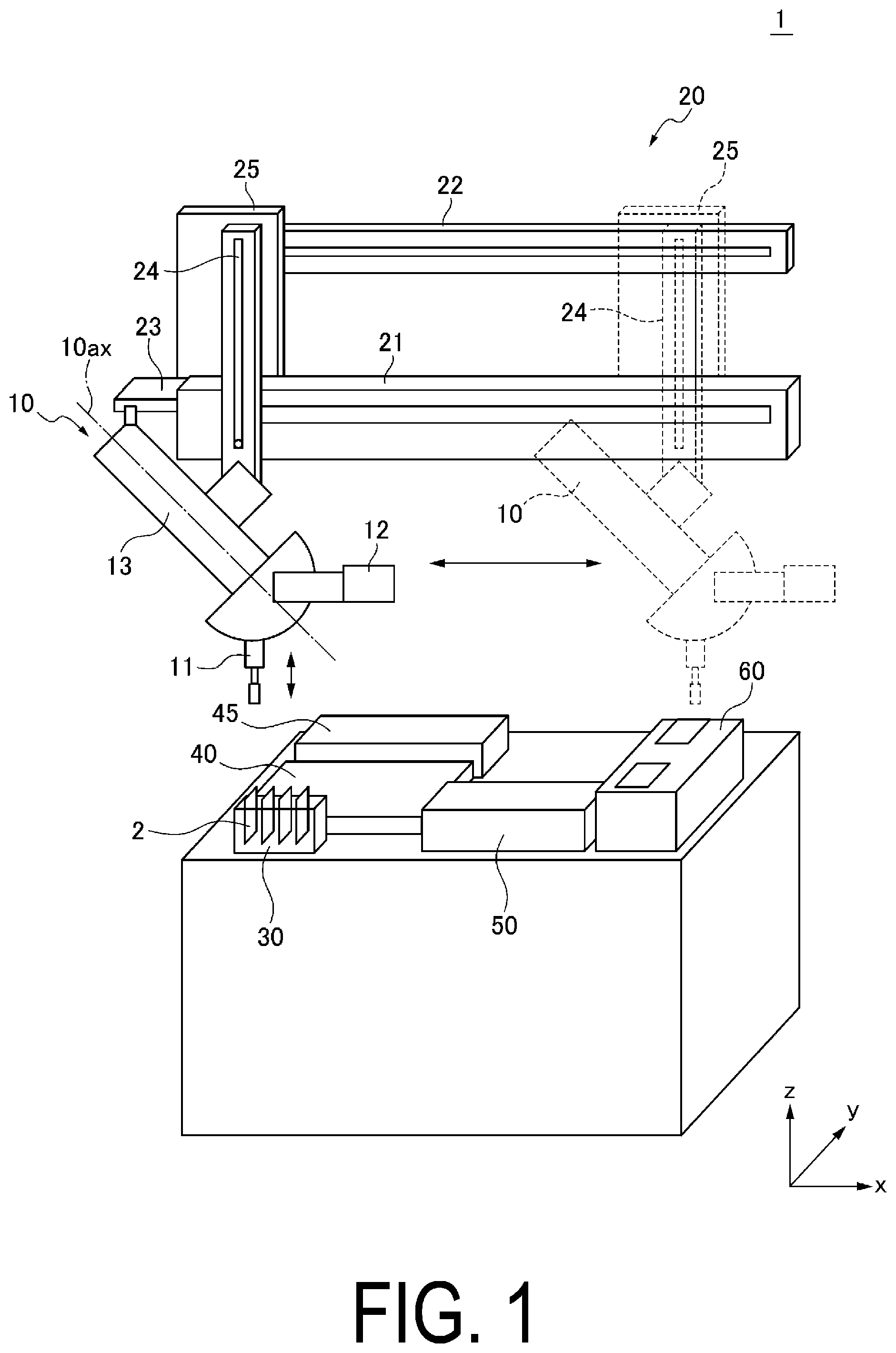
is a perspective view illustrating a schematic configuration of a paraffin-embedded block preparation device 1 of an embodiment of the present invention. is a perspective view illustrating a schematic configuration of the paraffin-embedded block preparation device 1 . is a perspective view illustrating an example of a schematic configuration of a holding portion 30 . is a diagram illustrating an example of a schematic configuration of a cassette holder 2 , with (A) being a front view and (B) being a side view. is a diagram illustrating a how a cassette 101 is set to the cassette holder 2 . is a perspective view illustrating an example of a schematic configuration of a chemical liquid bottle holding portion 40 and a temporary placement portion 45 . is a diagram illustrating an example of a schematic configuration of a bottle body 71 in which the cassette holder 2 is provided, with (A) being a front view of the cassette holder 2 and (B) being a side view of the cassette holder 2 . is a plan view illustrating a schematic configuration of the paraffin-embedded block preparation device 1 . is a perspective view illustrating an example of a schematic configuration of a paraffin fixing unit 60 . is a perspective view illustrating an example of a schematic configuration of the cassette holder 2 and a paraffin receiver 102 , with (A) being a perspective view of the paraffin receiver 102 , (B) being a perspective view illustrating a state where the cassette holder 2 is placed on the paraffin receiver 102 , and (C) being a cross-sectional view illustrating the state where the cassette holder 2 is placed on the paraffin receiver 102 . is a cross-sectional view illustrating an example of a schematic configuration of a paraffin discharge unit 62 . is a block diagram illustrating an electrical configuration of the paraffin-embedded block preparation device 1 . is a flowchart illustrating a flow of processing executed by the paraffin-embedded block preparation device 1 . is a flowchart illustrating a flow of processing (step S 20 ) of immersing the cassette holder 2 in chemical liquid. is a flowchart illustrating a flow of processing (step S 30 ) of immersing the cassette holder 2 in paraffin liquid. is a diagram illustrating the cassette holder 2 after processing executed by the paraffin-embedded block preparation device 1 . is a diagram illustrating how an embedded block is taken out from the cassette holder 2 . is a view illustrating the cassette 101 and an embedded block B taken out from the cassette holder 2 , with (A) being a side view and (B) being a perspective view. is a perspective view illustrating an overview of a cassette holder 3 . is a diagram illustrating an example of a schematic configuration of the cassette holder 3 , with (A) being a plan view and (B) being a side view. is a perspective view illustrating an overview of a cassette holder 3 A. is a diagram illustrating an overview of a cassette holder 4 , with (A) being a plan view and (B) being a side view. is a cross-sectional view illustrating an example of a schematic configuration of a bottle body 71 A in which the cassette holder 4 is provided. is a diagram illustrating an overview of a cassette holder 4 A. is a diagram illustrating an overview of a cassette holder 4 B. is a diagram illustrating an overview of a cassette holder 5 , with (A) being a plan view and (B) being a side view. is a cross-sectional view illustrating an example of a schematic configuration of a bottle body 71 A in which the cassette holder 5 is provided. is a diagram illustrating an overview of a cassette holder 5 A. is a diagram illustrating an overview of a cassette holder 5 B. is a diagram illustrating an overview of a cassette holder 6 , with (A) being a plan view and (B) being a side view. is a diagram illustrating an overview of a cassette holder 7 , with (A) being a plan view and (B) being a side view. is a diagram schematically illustrating how the cassette holder 7 is provided in the bottle body 71 A, with (A) illustrating a state before deformation of a projection 596 a , (B) illustrating how the projection 596 a deforms, and (C) illustrating a state where the projection 596 a is completely deformed. is a diagram illustrating an overview of a cassette holder 7 A. is a diagram illustrating an overview of a cassette holder 7 B. is a diagram illustrating an example of a schematic configuration of a cassette holder 8 , with (A) being a plan view and (B) being a side view. is a diagram illustrating an overview of a cassette holder 9 , with (A) being a plan view and (B) being a side view. is a diagram illustrating an example of a schematic configuration of a cassette holder 3 B, with (A) being an upper view and (B) being a plan view.
DESCRIPTION OF EMBODIMENTS
Hereinafter, embodiments of the present invention will be described in detail with reference to the drawings. The paraffin-embedded block preparation device of the present invention is, for example, a device for preparing a paraffin-fixed embedded block used for a genetic test such as an oncogene panel test. The cassette holder of the present invention is a member for holding a cassette for medical use, and is used for preparing a paraffin-fixed embedded block. First Embodiment are perspective views illustrating an example of a schematic configuration of a paraffin-embedded block preparation device 1 of an embodiment of the present invention. is an enlarged view of a main part of the paraffin-embedded block preparation device 1 . In the following description, an x direction and a y direction are defined as the horizontal direction, and a z direction is defined as the vertical direction. The x direction and the y direction are orthogonal to each other. The paraffin-embedded block preparation device 1 mainly includes a head 10 , a conveying unit 20 (corresponding to a first conveying unit), a holding portion 30 , a chemical liquid bottle holding portion 40 , a paraffin-filled bottle holding portion 50 , and a paraffin fixing unit 60 . The head 10 is provided to the conveying unit 20 and is disposed above the holding portion 30 , the chemical liquid bottle holding portion 40 , and the paraffin-filled bottle holding portion 50 . The head 10 mainly includes a cassette holder gripping unit 11 that grips a cassette holder 2 (described in detail below), a lid gripping unit 12 that grips a lid 72 (described in detail below), and a body portion 13 provided with the cassette holder gripping unit 11 and the lid gripping unit 12 . The cassette holder gripping unit 11 has two claws 11 a and 11 b (see ) provided to be movable in parallel, and grips the cassette holder 2 using the claws 11 a and 11 b . The lid gripping unit 12 has two claws 12 a and 12 b (see ) provided to be movable in parallel, and grips the lid 72 using the claws 12 a and 12 b. The cassette holder gripping unit 11 includes an opening/closing unit (not illustrated) that opens and closes the claws 11 a and 11 b between a closed position at which the cassette holder 2 is gripped and an open position at which the cassette holder 2 is not gripped. The lid gripping unit 12 is provided with an opening/closing unit (not illustrated) that opens and closes the claws 12 a and 12 b between a closed position at which the lid 72 is gripped and an open position at which the lid 72 is not gripped. The opening/closing unit includes an actuator and a transmission mechanism that transmits power from the actuator. The lid gripping unit 12 is provided so as to be rotatable about an axis 12 ax . The lid gripping unit 12 includes an actuator that rotates the lid gripping unit 12 and a transmission mechanism that transmits power from the actuator. The body portion 13 is provided so as to be rotatable about an axis 10 ax . The body portion 13 includes an actuator that rotates the body portion 13 and a transmission mechanism that transmits power from the actuator. The head 10 can adjust the orientations of the cassette holder gripping unit 11 and the lid gripping unit 12 by rotating the body portion 13 about the axis 10 ax . The axis 10 ax is inclined at approximately 45 degrees with respect to the z direction. The longitudinal directions of the cassette holder gripping unit 11 and the lid gripping unit 12 are inclined at approximately 45 degrees with respect to the axis 10 ax of the head 10 . Therefore, when the head 10 is rotated about the axis 10 ax , the positions and orientations of the cassette holder gripping unit 11 and the lid gripping unit 12 are changed between: a state where the longitudinal direction of the cassette holder gripping unit 11 is along the z direction (the cassette holder gripping unit 11 holds the cassette holder 2 vertically) and the longitudinal direction of the lid gripping unit 12 is along the x direction; and a state where the longitudinal direction of the cassette holder gripping unit 11 is along the x direction (the cassette holder gripping unit 11 holds the cassette holder 2 horizontally) and the longitudinal direction of the lid gripping unit 12 is along the z direction. The conveying unit 20 makes the head 10 move in the horizontal direction or the vertical direction. The conveying unit 20 mainly includes rails 21 and 22 extending in the x direction, a rail 23 extending in the y direction, a rail 24 extending in the z direction, and a driving unit 25 including an actuator (not illustrated). The rail 21 is provided with the rail 24 and the rail 22 is provided with the driving unit 25 . The driving unit 25 is provided with the rail 23 . The driving unit 25 makes the head 10 and the rails 23 and 24 move in the x direction along the rail 21 , and makes the head 10 move in the y direction along the rail 23 . The head 10 is provided to the rail 24 . The driving unit 25 moves the head 10 and the rails 23 and 24 in the z direction. Thus, the conveying unit 20 can convey the head 10 , that is, the cassette holder 2 gripped by the cassette holder gripping unit 11 among the holding portion 30 , the chemical liquid bottle holding portion 40 , the paraffin-filled bottle holding portion 50 , and the paraffin fixing unit 60 . The holding portion 30 holds the cassette holder vertically. is a perspective view illustrating an example of a schematic configuration of the holding portion 30 . The holding portion 30 mainly includes a frame 31 and a sensor 32 . The frame 31 includes two plate-shaped portions 31 a and 31 b disposed in parallel while extending substantially along the x direction. The plate-shaped portions 31 a and 31 b are respectively provided with four slits 31 c and four slits 31 d . The slits 31 c and 31 d extend along the z direction, and the positions of the slits 31 c and the slits 31 d in the x direction substantially match. With the slits 31 c and 31 d , the holding portion 30 is provided with holding portions 30 a , 30 b , 30 c , and 30 d adjacent to each other. The cassette holder 2 is inserted into the slits 31 c and 31 d . As a result, the cassette holder 2 is held vertically in the holding portions 30 a , 30 b , 30 c , and 30 d . When the cassette holder 2 is vertically oriented, the longitudinal direction of the cassette holder 2 is along the vertical direction. In the mode illustrated in , the holding portions 30 a , 30 b , 30 c , and 30 d are provided adjacent to each other, but the holding portions 30 a , 30 b , 30 c , and 30 d may not be adjacent to each other. The cassette holder 2 will now be described. is a diagram illustrating an example of a schematic configuration of the cassette holder 2 , with (A) being a plan view and (B) being a side view. The cassette holder 2 mainly includes a cassette receiving portion 91 to which a cassette 101 (see ) is set, a plate-shaped portion 92 having a substantially plate-like shape, and a protrusion 93 provided on the cassette receiving portion 91 . The cassette receiving portion 91 and the protrusion 93 are provided with a pair of slits 94 a and 94 b. In the description of the cassette holder 2 , a direction substantially orthogonal to the extending direction of the plate-shaped portion 92 is defined as an upward-downward direction, a protruding direction of the protrusion 93 is defined as a downward direction, and a direction opposite to the protruding direction of the protrusion 93 is defined as an upward direction. The plan view in (A) illustrates the cassette holder 2 as viewed from above. The cassette receiving portion 91 has a rectangular shape in plan view (when the cassette holder 2 is viewed from above), and mainly includes a bottom surface 91 a and a rib 91 b . The bottom surface 91 a is a flat surface with which the lower surface of the cassette 101 comes into contact when the cassette 101 is set, and has a rectangular shape in plan view. The bottom surface 91 a is provided with a plurality of through holes 97 . The rib 91 b protrudes upward from the bottom surface 91 a . The rib 91 b has a rectangular shape in plan view and comes into contact with the peripheral edge of the cassette 101 when the cassette 101 is set. However, the shape of the rib 91 b is not limited to this. For example, the rib may have a rectangular U shape in plan view, or may be made up of two parallel bar-shaped portions. The rib 91 b is provided with a cassette pressing claw 91 d for holding the cassette 101 when the cassette 101 is set to the cassette receiving portion 91 . However, the cassette pressing claw 91 d is not essential. The bottom surface 91 a is provided with the protrusion 93 protruding downward. The inside of the protrusion 93 is hollow. In the present embodiment, the protrusion 93 has a substantially truncated pyramid shape, but the shape of the protrusion 93 is not limited to this. The protrusion 93 is provided with the plurality of through holes 97 . In the present embodiment, the through holes 97 are provided in a bottom surface 93 a of the protrusion 93 and is not provided in a side surface 93 b , but may be provided in the side surface 93 b. is a diagram illustrating a state how the cassette 101 is set to the cassette holder 2 . In a state where a specimen (hereinafter, referred to as sample S) is placed on the bottom surface 93 a , the cassette 101 is attached to the cassette receiving portion 91 . When a rear end 101 b of the cassette 101 is inserted into the rib 91 b after a front end 101 a of the cassette 101 has been brought into contact with a projection 91 e of the rib 91 b , the cassette pressing claw 91 d is caught by the rear end 101 b . As a result, the cassette 101 is attached to the cassette holder 2 , and the sample S is sealed in the cassette holder 2 . The description will now return to . The bottom surface 91 a , the rib 91 b , and the side surface 93 b are provided with the slits 94 a and 94 b . The slits 94 a and 94 b are substantially parallel to the short sides of the rib 91 b , and are collinearly arranged in plan view of the cassette holder 2 . A height h 1 of the slits 94 a and 94 b in side view is equal to or more than half of a distance h 2 between a distal end of the rib 91 b and a distal end of the protrusion 93 . The plate-shaped portion 92 is provided on one side 91 c of the two short sides of the rib 91 b . The plate-shaped portion 92 extends substantially parallel to the bottom surface 91 a . The plate-shaped portion 92 has a substantially rectangular shape in plan view of the cassette holder 2 , and has two sides 92 a and 92 b along a direction (first direction) substantially parallel to the long side of the rib 91 b . The sides 92 a and 92 b have substantially the same length as the long side of the rib 91 b in plan view. As a result, the direction along the sides 92 a and 92 b is the longitudinal direction of the cassette holder 2 . The sides 92 a and 92 b are provided with projections 95 a and 95 b , respectively. The projections 95 a and 95 b are a pair of projections protruding outward in plan view. The sides 92 a and 92 b are provided with projections 96 a and 96 b , respectively. The projections 96 a and 96 b are a pair of projections protruding outward in plan view. The heights of the projections 96 a and 96 b are lower than the heights of the projections 95 a and 95 b . In other words, a width w 2 between both ends of the projections 96 a and 96 b is smaller than a width w 1 between both ends of the projections 95 a and 95 b . The projections 96 a and 96 b are provided between the cassette receiving portion 91 and the projections 95 a and 95 b. The distal end of each of the projections 96 a and 96 b is configured to be movable in a direction (second direction) substantially parallel to the short side (side 91 c ) of the rib 91 b . The projections 96 a and 96 b respectively include flat surface portions 97 a and 97 b substantially parallel to the sides 92 a and 92 b , and L-shaped arm portions 98 a and 98 b connecting the flat surface portions 97 a and 97 b and the sides 92 a and 92 b . The flat surface portions 97 a and 97 b are substantially orthogonal to a plane including the plate-shaped portion 92 . The sides 92 a and 92 b respectively include recesses 92 e and 92 f . The flat surface portions 97 a and 97 b move in a direction substantially parallel to the side 91 c , with base end portions of the arm portions 98 a and 98 b deforming inside the recesses 92 e and 92 f. Both ends of the flat surface portions 97 a and 97 b are bent toward the plate-shaped portion 92 . The connection portions between the flat surface portions 97 a and 97 b and the bent portions of both ends may have an edge shape or an arc shape (R shape). However, the configuration enabling the movement of the distal ends of the projections 96 a and 96 b in the direction substantially parallel to the side 91 c is not limited to this. The description will now return to . The sensor 32 is a sensor that detects whether the cassette holder 2 is held in the holding portions 30 a , 30 b , 30 c , and 30 d , and is provided for each of the holding portions 30 a , 30 b , 30 c , and 30 d . The sensor 32 is, for example, a transmission-type optical sensor, and has a light emitting unit and a light receiving unit facing each other across the slit 31 c . The sensor 32 detects the presence or absence of the cassette holder 2 , based on a fact that light emitted from the light emitting unit is blocked by the cassette holder 2 (projection 95 a ) inserted in the slit 31 c so as to be not received by the light receiving unit. A sensor 33 is provided adjacent to the frame 31 . The sensor 33 is, for example, a reflective optical sensor, and detects the position of the cassette holder gripping unit 11 . The description will now return to . In the chemical liquid bottle holding portion 40 , a plurality of chemical liquid bottles 70 filled with chemical liquid containing formalin, ethanol, and xylene are provided adjacent to each other. When the cassette holder 2 is inserted into the chemical liquid bottles 70 , the sample S inside the cassette holder 2 is immersed in the chemical liquid. A temporary placement portion 45 for temporarily placing a lid is provided adjacent to the chemical liquid bottle holding portion 40 . is a perspective view illustrating an example of a schematic configuration of the chemical liquid bottle holding portion 40 and the temporary placement portion 45 . The chemical liquid bottle holding portion 40 mainly includes plate-shaped portions 41 and 42 extending along the horizontal direction. The plate-shaped portion 41 is provided with a plurality of holes 41 a. The chemical liquid bottles 70 are provided in the holes 41 a. The chemical liquid bottle 70 includes a bottle body 71 a cross-sectional shape of which along a plane orthogonal to the center axis is polygonal, and the lid 72 that covers an opening portion of the bottle body 71 . The bottle body 71 is made of, for example, glass. The bottle body 71 and the lid 72 are screwed together. The shape of the hole 41 a corresponds to the outer shape of the bottle body 71 , and the bottle body 71 is inserted into the hole 41 a . The holes 41 a are arranged two-dimensionally along the x direction and the y direction. Therefore, the chemical liquid bottles 70 are two-dimensionally arranged in the chemical liquid bottle holding portion 40 . When the bottle body 71 is inserted into the hole 41 a , the bottom surface of the bottle body 71 is placed on the plate-shaped portion 42 . The cassette holder 2 is inserted into the chemical liquid bottle 70 . is a diagram illustrating an example of a schematic configuration of the bottle body 71 in which the cassette holder 2 is provided, with (A) being a front view of the cassette holder 2 and (B) being a side view of the cassette holder 2 . is a cross-sectional view of the bottle body 71 , with hatching indicating a cross section omitted. The bottle body 71 mainly includes a bottom surface 71 a , a side surface 71 b that forms a hexagonal cylindrical shape and is provided on the upper side of the bottom surface 71 a , and a tubular portion 71 c that has a cylindrical shape and is provided on the upper side of the side surface 71 b . The tubular portion 71 c has an outer circumference surface provided with a thread 71 d screwed with a thread formed on the lid 72 . The tubular portion 71 c has an opening portion 71 e as an upper end surface. The cassette holder 2 is inserted into the bottle body 71 through the opening portion 71 e . During this process, the cassette holder 2 is vertically orientated with the plate-shaped portion 92 extending along the vertical direction. Since the width w 1 (see ) between both ends of the projections 95 a and 95 b is larger than a diameter D of the tubular portion 71 c , the projections 95 a , 95 b are caught on the opening portion 71 e , whereby the cassette holder 2 is positioned in the z direction. The width w 2 (see ) between both ends of the projections 96 a and 96 b is smaller than the width w 1 (see ) between both ends of the projections 95 a and 95 b . Thus, the distal ends (the flat surface portions 97 a and 97 b ) of the projections 96 a and 96 b are configured to be movable in a width direction of the cassette holder 2 . Therefore, when the cassette holder 2 is inserted into the bottle body 71 , the flat surface portions 97 a and 97 b come into contact with an inner circumference surface of the tubular portion 71 c , and the flat surface portions 97 a and 97 b press the inner circumference surface of the tubular portion 71 c . As a result, the cassette holder 2 is fixed to the bottle body 71 with the cassette holder 2 inserted in the bottle body 71 prevented from rotating. The description will now return to . The chemical liquid bottle holding portion 40 includes chemical liquid bottle holding portions 40 a , 40 b , 40 c , and 40 d adjacently arranged. The chemical liquid bottle holding portions 40 a to 40 d are provided adjacent to each other in the y direction herein, but may not be adjacent to each other. The chemical liquid bottle holding portions 40 a to 40 d respectively correspond to the holding portions 30 a to 30 d . The cassette holder 2 held in the holding portion 30 a is immersed in the chemical liquid bottle 70 provided in the chemical liquid bottle holding portion 40 a . The cassette holder 2 held in the holding portion 30 b is immersed in the chemical liquid bottle 70 provided in the chemical liquid bottle holding portion 40 b . The cassette holder 2 held in the holding portion 30 c is immersed in the chemical liquid bottle 70 provided in the chemical liquid bottle holding portion 40 c . The cassette holder 2 held in the holding portion 30 d is immersed in the chemical liquid bottle 70 provided in the chemical liquid bottle holding portion 40 d. is a plan view illustrating a schematic configuration of the paraffin-embedded block preparation device 1 . In , the head 10 and the conveying unit 20 are omitted. The chemical liquid bottle holding portions 40 a to 40 d are regions elongated in the x direction, and are respectively provided with chemical liquid bottle groups 70 a to 70 d . The chemical liquid bottle groups 70 a to 70 d include a plurality of chemical liquid bottles 70 provided along the x direction. The cassette holder 2 held in the holding portion 30 a is inserted into the chemical liquid bottle group 70 a . The cassette holder 2 held in the holding portion 30 b is inserted into the chemical liquid bottle group 70 b . The cassette holder 2 held in the holding portion 30 c is inserted into the chemical liquid bottle group 70 c . The cassette holder 2 held in the holding portion 30 d is inserted into the chemical liquid bottle group 70 d. Each of the chemical liquid bottle groups 70 a to 70 d includes seven chemical liquid bottles 70 . The chemical liquid bottle groups 70 a to 70 d each include a chemical liquid bottle 70 h (corresponding to a first chemical liquid bottle) filled with formalin, chemical liquid bottles 70 i , 70 j , and 70 k (corresponding to a second chemical liquid bottle) filled with ethanol, and chemical liquid bottles 70 l , 70 m , and 70 n (corresponding to a third chemical liquid bottle) filled with xylene, arranged in this order from −x side. The cassette holder 2 is inserted into the chemical liquid bottles 70 h , 70 i , 70 j , 70 k , 70 l , 70 m and 70 n in this order. Although some of the chemical liquid bottles 70 are not illustration in , the chemical liquid bottles 70 are actually inserted into all the holes 41 a in at least two of the chemical liquid bottle holding portions 40 a to 40 d. The temporary placement portion 45 is provided on the farther side (+y side) of the chemical liquid bottle holding portion 40 . The temporary placement portion 45 has a lid placement portion 45 a on which the lid 72 removed from the bottle body 71 is placed, and a tentative lid placement portion 45 b on which a tentative lid 73 is placed. The tentative lid 73 covers the bottle body 71 into which the cassette holder 2 has been inserted. The description will now return to . The paraffin-filled bottle holding portion 50 is provided adjacent to the chemical liquid bottle holding portion 40 . However, the paraffin-filled bottle holding portion 50 and the chemical liquid bottle holding portion 40 may not be adjacent to each other. The paraffin-filled bottle holding portion 50 is provided with a paraffin-filled bottle 75 filled with paraffin in a liquid form (hereinafter, referred to paraffin liquid). The paraffin-filled bottle 75 is similar to the chemical liquid bottle 70 except that the liquid filled therein is paraffin, and includes the bottle body 71 and the lid 72 . As illustrated in , the paraffin-filled bottle holding portion 50 mainly includes plate-shaped portions 51 and 52 extending along the horizontal direction, and a heating portion 53 . Each of the plate-shaped portions 51 is provided with a plurality of holes 51 a . The shape of the hole 51 a corresponds to the outer shape of the paraffin-filled bottle 75 , and the paraffin-filled bottle 75 is inserted into the hole 51 a . The holes 51 a are arranged two-dimensionally along the x direction and the y direction. Therefore, the paraffin-filled bottles 75 are two-dimensionally arranged in the paraffin-filled bottle holding portion 50 . When the paraffin-filled bottle 75 is inserted into the hole 51 a , the bottom surface of the paraffin-filled bottle 75 is placed on the plate-shaped portion 52 . The heating portion 53 is provided so as to cover the plate-shaped portions 51 and 52 . The heating portion 53 heats the liquid paraffin filling the paraffin-filled bottle 75 to about 60° C., to prevent solidification of the liquid paraffin. Note that the form of the heating portion 53 is not limited to the illustrated form. For example, the heating portion 53 may be formed by attaching a heating wire to the plate-shaped portions 51 and 52 . The paraffin-filled bottle holding portion 50 includes paraffin-filled bottle holding portions 50 a , 50 b , 50 c , and 50 d adjacently arranged. The paraffin-filled bottle holding portions 50 a to 50 d are provided adjacent to each other in the y direction herein, but may not be adjacent to each other. The paraffin-filled bottle holding portions 50 a to 50 d are regions elongated in the x direction, and are respectively provided with paraffin-filled bottle groups 75 a to 75 d . The paraffin-filled bottle groups 75 a to 75 d include the plurality of paraffin-filled bottles 75 provided along the x direction. The paraffin-filled bottle holding portions 50 a to 50 d respectively correspond to the holding portions 30 a to 30 d and the chemical liquid bottle holding portions 40 a to 40 d . The cassette holder 2 held in the holding portion 30 a is inserted in the paraffin-filled bottle 75 provided to the paraffin-filled bottle holding portion 50 a . The cassette holder 2 held in the holding portion 30 b is inserted in the paraffin-filled bottle 75 provided to the paraffin-filled bottle holding portion 50 b . The cassette holder 2 held in the holding portion 30 c is inserted in the paraffin-filled bottle 75 provided to the paraffin-filled bottle holding portion 50 c . The cassette holder 2 held in the holding portion 30 d is inserted in the paraffin-filled bottle 75 provided to the paraffin-filled bottle holding portion 50 d. The paraffin-filled bottle groups 75 a to 75 d each include three paraffin-filled bottles 75 . The paraffin-filled bottle groups 75 a to 75 d each include paraffin-filled bottles 75 h , 75 i , and 75 j in this order from the −x side. The cassette holder 2 is inserted in the paraffin-filled bottles 75 h , 75 i , and 75 j in this order. Although some of the paraffin-filled bottles 75 are not illustrated in , the paraffin-filled bottles 75 are actually inserted into all the holes 51 a in at least two of the paraffin-filled bottle holding portions 50 a to 50 d. The description will now return to . The paraffin fixing unit 60 is provided adjacent to the paraffin-filled bottle holding portion 50 . However, the paraffin fixing unit 60 and the paraffin-filled bottle holding portion 50 may not be adjacent to each other. The paraffin fixing unit 60 includes a placement portion 61 on which the cassette holder 2 is horizontally placed, a paraffin discharge unit 62 including a nozzle that discharges the paraffin, and a cooling unit 63 including a cooling mechanism. The placement portion 61 is provided to be movable in the horizontal direction (here, the y direction). The paraffin discharge unit 62 and the cooling unit 63 are provided adjacent to each other in the moving direction of the placement portion 61 which is the y direction herein. is a perspective view illustrating an example of a schematic configuration of the paraffin fixing unit 60 . In , the paraffin discharge unit 62 is omitted. The placement portion 61 is a plate-shaped member extending along the horizontal direction. The cassette holder is placed horizontally on the placement portion 61 . The cassette holder 2 horizontally disposed corresponds to a case where the extending direction of the plate-shaped portion 92 is the horizontal direction and the cassette holder 2 faces upward (the protrusion 93 protrudes vertically downward). The cooling unit 63 mainly includes a flat surface portion 63 a on which the cassette holder 2 is placed and a cooling mechanism 63 b that cools the flat surface portion 63 a . The cooling mechanism 63 b includes a cooling unit such as a Peltier element. The flat surface portion 63 a is preferably made of metal to be more efficiently cooled by the cooling mechanism 63 b. The placement portion 61 is provided with four holes 61 a , 61 b , 61 c , and 61 d . The cassette holders 2 and paraffin receivers 102 are horizontally placed in the holes 61 a to 61 d. is a perspective view illustrating an example of a schematic configuration of the cassette holder 2 and the paraffin receiver 102 , with (A) being a perspective view of the paraffin receiver 102 , (B) being a perspective view illustrating a state where the cassette holder 2 is placed on the paraffin receiver 102 , and (C) being a cross-sectional view illustrating the state where the cassette holder 2 is placed on the paraffin receiver 102 . The paraffin receiver 102 mainly includes a plate-shaped portion 102 a with which the cassette holder 2 comes into contact, a protrusion 102 b formed in the plate-shaped portion 102 a , and a rib 102 c formed around the plate-shaped portion 102 a . When the cassette holder 2 is placed on the paraffin receiver 102 , the bottom surface 91 a comes into contact with the plate-shaped portion 102 a , and the protrusion 93 is inserted into the protrusion 102 b. The description will now return to . The paraffin receivers 102 are placed in the holes 61 a to 61 d in advance. The cassette holders 2 are placed on the paraffin receivers 102 placed in the holes 61 a to 61 d in advance. The holes 61 a to 61 d respectively correspond to the holding portions 30 a to 30 d . The cassette holder 2 held in the holding portion 30 a is placed on the paraffin receiver 102 placed in the hole 61 a . The cassette holder 2 held in the holding portion 30 b is placed on the paraffin receiver 102 placed in the hole 61 b . The cassette holder 2 held in the holding portion 30 c is placed on the paraffin receiver 102 placed in the hole 61 c . The cassette holder 2 held in the holding portion 30 d is placed on the paraffin receiver 102 placed in the hole 61 d. The paraffin fixing unit 60 includes conveying units 66 and 67 (corresponding to second conveying unit) that convey the placement portion 61 that is, the cassette holder 2 in the horizontal direction. The conveying unit 66 moves the placement portion 61 in the −y direction from a position indicated by solid line in , and disposes the cassette holders 2 provided in the holes 61 a to 61 d below (a region A indicated by dotted line in ) a nozzle 62 d (described in detail below) of the paraffin discharge unit 62 . The conveying unit 67 moves the placement portion 61 in the −y direction, so that the cassette holders 2 provided in the holes 61 a to 61 d are moved onto the cooling unit 63 from the region A to be placed on the flat surface portion 63 a. In the present invention, the paraffin fixing unit 60 includes the two conveying units 66 and 67 , but the paraffin fixing unit 60 may include one conveying unit having the functions of the conveying units 66 and 67 . is a cross-sectional view illustrating an example of a schematic configuration of the paraffin discharge unit 62 . The paraffin discharge unit 62 mainly includes a housing 62 a , a tank 62 b , a pipe 62 c , and the nozzle 62 d . The tank 62 b and the pipe 62 c are provided inside the housing 62 a , and the housing 62 a is provided with the nozzle 62 d. The housing 62 a includes a heating portion not illustrated. The heating portion heats the tank 62 b , the pipe 62 c and the nozzle 62 d to about 60° C. at which the paraffin turns into liquid. The interior of the tank 62 b is filled with the liquid paraffin. The paraffin is supplied from the tank 62 b to the nozzle 62 d through the pipe 62 c , and discharged from the nozzle 62 d. A vibration table 68 is provided on the lower side of the nozzle 62 d in the vertical direction (the region A indicated by the dotted line in ). The vibration table 68 is capable of vibrating, for example, for translational motions in the three directions of x, y, and z and rotational motions about the respective axes. The vibration table 68 may be capable of vibrating in at least one direction, an is preferably capable of vibrating in a horizontal direction. Because the vibration table 68 is already known, a description thereof is omitted. Further, the vibration table 68 includes a heating portion (not illustrated) and heats the cassette holder 2 placed on the vibration table 68 . However, the heating portion is not essential in the vibration table 68 . is a block diagram illustrating an electrical configuration of the paraffin-embedded block preparation device 1 . The paraffin-embedded block preparation device 1 mainly includes a control unit 110 , a communication unit 112 , and a storage unit 114 . The control unit 110 mainly includes a Central Processing Unit (CPU), and operates in accordance with a program stored in the storage unit 114 . The head 10 (the cassette holder gripping unit 11 , the lid gripping unit 12 , and the body portion 13 ), the conveying unit 20 (the driving unit 25 ), the holding portion 30 (the sensors 32 and 33 ), the paraffin fixing unit 60 (the paraffin discharge unit 62 , the cooling unit 63 , the conveying unit 66 and 67 , and the vibration table 68 ) are connected to the control unit 110 , and the control unit 110 controls each of these. Specifically, the control unit 110 controls the cassette holder gripping unit 11 to open and close the claws 11 a and 11 b , controls the lid gripping unit 12 to open and close the claws 12 a and 12 b , and rotates the lid gripping unit 12 . The control unit 110 controls the body portion 13 to rotate the head 10 about the axis 10 ax . The control unit 110 controls the conveying unit 20 to move the head 10 in the horizontal direction and the vertical direction. The control unit 110 acquires signals from the sensors 32 and 33 and controls the head 10 and the conveying unit 20 based on the signals. The control unit 110 controls the conveying unit 66 and 67 to move the placement portion 61 in the horizontal direction. The control unit 110 controls the paraffin discharge unit 62 to discharge paraffin from the nozzle 62 d . The control unit 110 controls the vibration table 68 to vibrate the vibration table 68 and to heat the vibration table 68 by the heating portion (not illustrated). Details of the operation of the control unit 110 will be described in detail below. The communication unit 112 includes a communication interface or the like for communicating with an external device. The storage unit 114 is formed by a hard disk or the like. The storage unit 114 stores various programs and various pieces of information required for the control unit 110 to execute the processing, and information on results of the processing. The configuration of the paraffin-embedded block preparation device 1 illustrated in is described as a main configuration for describing the features of the present embodiment, and does not exclude, for example, a configuration of a general information processing apparatus. is a flowchart illustrating a flow of processing executed by the paraffin-embedded block preparation device 1 . The following processing is mainly executed by the control unit 110 . The control unit 110 causes the cassette holder gripping unit 11 to grip the cassette holder 2 provided to the holding portion 30 (step S 10 ). The control unit 110 detects which of the holding portions 30 a to 30 d is holding the cassette holder 2 , using the sensor 32 . Then, the control unit 110 makes the conveying unit 20 move the cassette holder gripping unit 11 to be above the holding portion 30 a , 30 b , 30 c , 30 d in which the cassette holder 2 is detected. The control unit 110 moves the cassette holder gripping unit 11 downward with the claws 11 a and 11 b opened, and closes the claws 11 a and 11 b to make the cassette holder gripping unit 11 grip the cassette holder 2 . For example, when cassette holders 2 are held by all of the holding portions 30 a to 30 d , the cassette holder gripping unit 11 grips the cassette holder 2 held in the holding portions 30 a , 30 b , 30 c , and 30 da . For example, when the cassette holders 2 are held in the holding portions 30 b to 30 d , the cassette holder gripping unit 11 grips the cassette holder 2 held in the holding portion 30 b. The control unit 110 positions the cassette holder gripping unit 11 above the holding portion 30 b , 30 c , 30 d , based on a result of the detection by the sensor 33 , with the claws 11 a and 11 b arranged in the open position. Then, the control unit 110 moves the claws 11 a and 11 b from the open position to the closed position to grip the cassette holder 2 with the claws 11 a and 11 b. Next, the control unit 110 immerses the cassette holder 2 in the chemical liquid (step S 20 ). The control unit 110 moves the cassette holder gripping unit 11 to be above the chemical liquid bottle holding portion 40 a , 40 b , 40 c , 40 d corresponding to the holding portion 30 a , 30 b , 30 c , 30 d by which the cassette holder 2 gripped by the cassette holder gripping unit 11 has been held. For example, when the cassette holder gripping unit 11 is gripping the cassette holder 2 held in the holding portion 30 a , the control unit 110 moves the cassette holder gripping unit 11 to be above the chemical liquid bottle holding portion 40 a . For example, when the cassette holder gripping unit 11 is gripping the cassette holder 2 held in the holding portion 30 b , the control unit 110 moves the cassette holder gripping unit 11 to be above the chemical liquid bottle holding portion 40 b. is a flowchart illustrating a flow of processing (step S 20 ) of immersing the cassette holder 2 in the chemical liquid. Hereinafter, the flow of step S 20 will be described with reference to an example in which the cassette holder gripping unit 11 grips the cassette holder 2 held in the holding portion 30 a. The control unit 110 opens the lid 72 of the chemical liquid bottle 70 (step S 201 ). When step S 201 is performed for the first time, the control unit 110 opens the lid of the chemical liquid bottle 70 h positioned at the leftmost side (−x side) among the chemical liquid bottles 70 arranged in the chemical liquid bottle holding portion 40 a. The processing of step S 201 will be described. First, the control unit 110 rotates the head 10 about the axis 10 ax to change the orientation of the head 10 from a state in which the longitudinal direction of the cassette holder gripping unit 11 is along the z direction and the longitudinal direction of the lid gripping unit 12 is along the x direction to a state in which the longitudinal direction of the cassette holder gripping unit 11 is along the x direction and the longitudinal direction of the lid gripping unit 12 is along the z direction. Next, the control unit 110 moves the claws 12 a and 12 b to the open state and moves the lid gripping unit 12 vertically downward (−z direction). Next, the control unit 110 moves the claws 12 a and 12 b to the closed state to grip the lid 72 with the lid gripping unit 12 , rotates the lid gripping unit 12 gripping the lid 72 to rotate the lid 72 relative to the bottle body 71 to remove the lid 72 from the bottle body 71 , and moves the lid gripping unit 12 vertically upward (in the +z direction). Since the bottle body 71 and the hole 41 a are both hexagonal when viewed in the z direction, the bottle body 71 does not rotate even when the lid 72 is rotated by the lid gripping unit 12 , and the lid 72 can be removed from the bottle body 71 without gripping the bottle body 71 . Next, the control unit 110 moves the head 10 to the cassette holder 2 positioned above the chemical liquid bottle 70 whose lid 72 has been opened in step S 201 (step S 202 ). Then, the control unit 110 inserts the cassette holder 2 into the chemical liquid bottle 70 whose lid 72 has been opened in step S 201 , to immerse the cassette holder 2 in the chemical liquid (step S 203 ). The processing of step S 203 will be described. First, the control unit 110 rotates the head 10 about the axis 10 ax to change the orientation of the head 10 from a state in which the longitudinal direction of the cassette holder gripping unit 11 is along the x direction and the longitudinal direction of the lid gripping unit 12 is along the z direction to a state in which the longitudinal direction of the cassette holder gripping unit 11 is along the z direction and the longitudinal direction of the lid gripping unit 12 is along the x direction. Next, the control unit 110 moves the cassette holder gripping unit 11 in the −z direction to insert the cassette holder 2 into the bottle body 71 . When the cassette holder 2 is inserted in the bottle body 71 , the control unit 110 moves the claws 11 a and 11 b to the open state to release the gripping of the cassette holder 2 . As illustrated in , since the projections 95 a and 95 b of the cassette holder 2 are caught on the opening portion 71 e , the cassette holder 2 does not fall into the bottle body 71 . In addition, since the distal ends (flat surface portions 97 a and 97 b ) of the projections 96 a and 96 b of the cassette holder 2 are in contact with the inner circumference surface of the tubular portion 71 c and the flat surface portions 97 a and 97 b press the inner circumference surface of the tubular portion 71 c , the cassette holder 2 inserted in the bottle body 71 does not rotate. The description will now return to . The control unit 110 moves the head 10 in the +z direction, after bringing the claws 11 a and 11 b into the open state to release the gripping of the cassette holder 2 . Then, the processing in step S 203 ends. Next, the control unit 110 puts the tentative lid 73 on the chemical liquid bottle 70 into which the cassette holder 2 has been inserted in step S 203 (step S 204 ). The processing of step S 204 will be described. First, the control unit 110 rotates the head 10 about the axis 10 ax to change the orientation of the head 10 from a state in which the longitudinal direction of the cassette holder gripping unit 11 is along the z direction and the longitudinal direction of the lid gripping unit 12 is along the x direction to a state in which the longitudinal direction of the cassette holder gripping unit 11 is along the x direction and the longitudinal direction of the lid gripping unit 12 is along the z direction. Then, the control unit 110 moves the head 10 in the horizontal direction (at least one of the x direction and the y direction) and the +z direction to move the head 10 to be above the temporary placement portion 45 . Then, the control unit 110 places the lid 72 gripped by the lid gripping unit 12 on the lid placement portion 45 a. Next, the control unit 110 causes the lid gripping unit 12 to grip the tentative lid 73 placed on the tentative lid placement portion 45 b . Specifically, the control unit 110 moves the head 10 to be above the lid placement portion 45 a , moves the head 10 in the −z direction, and then moves the claws 12 a and 12 b to the open state to place the lid 72 on the lid placement portion 45 a . The control unit 110 moves the head 10 in the +z direction, then moves the head 10 in the horizontal direction to position the lid gripping unit 12 above the tentative lid placement portion 45 b , and moves the claws 12 a and 12 b to the closed state after moving the head 10 in the −z direction, to grip the tentative lid 73 . Next, the control unit 110 places the gripped tentative lid 73 on the bottle body 71 so as to cover the opening portion of the bottle body 71 whose the lid 72 has been removed. Specifically, the control unit 110 moves the head 10 in the horizontal direction to position the tentative lid 73 above the bottle body 71 whose lid 72 has been removed, moves the head 10 in the −z direction, and then moves the claws 12 a and 12 b to the open state to place the tentative lid 73 on the bottle body 71 . Therefore, it is possible to prevent evaporation of and emission of odor from the chemical liquid. Then, the processing in step S 204 ends. The control unit 110 determines whether a predetermined period of time has elapsed after the processing in step S 203 has started (step S 205 ). The predetermined period of time is, for example, any period of time (24 hours in the present embodiment) between 6 and 48 hours when the chemical liquid bottle 70 into which the cassette holder 2 is inserted in step S 203 is the chemical liquid bottle 70 h , and is one hour in a case of each of the chemical liquid bottles 70 i , 70 j , 70 k , 70 l , 70 m , and 70 n. The control unit 110 makes the cassette holder 2 move up and down inside the chemical liquid bottle 70 at a constant time interval until the predetermined period of time elapses after the start of the processing in step S 203 (during the processing in step S 205 ) to stir the chemical liquid filled in the chemical liquid bottle 70 . For example, the control unit 110 makes the cassette holder gripping unit 11 grip the cassette holder 2 and makes the head 10 sequentially move by a short distance (for example, about 10 mm to 30 mm) in the +z direction and the −z direction. The constant time is, for example, 15 minutes. Thus, a new chemical liquid can be supplied to the vicinity of the sample S. When the predetermined period of time has not elapsed after the start of the processing in step S 203 (NO in step S 205 ), the control unit 110 repeats step S 205 . When the predetermined period of time has elapsed from the start of the processing in step S 203 (YES in step S 205 ), the control unit 110 removes the tentative lid 73 from the bottle body 71 (step S 206 ), and takes out the cassette holder 2 from the bottle body 71 whose tentative lid 73 has been removed (step S 207 ). The processing of step S 206 will be described. First, the control unit 110 moves the head 10 in the horizontal direction and the vertical direction to dispose the head 10 above the chemical liquid bottle 70 into which the cassette holder 2 has been inserted. At this time, the head 10 is in a state in which the longitudinal direction of the lid gripping unit 12 is along the z direction. Next, the control unit 110 moves the claws 12 a and 12 b to the open state and moves the head 10 in the −z direction, and then moves the claws 12 a and 12 b to the closed state to make the lid gripping unit 12 grip the tentative lid 73 . Then, the control unit 110 moves the head 10 in the +z direction to remove the tentative lid 73 from the bottle body 71 , and rotates the head 10 about the axis 10 ax to achieve a state where the longitudinal direction of the cassette holder gripping unit 11 is along the z direction. Then, the processing in step S 206 ends. The processing of step S 207 will be described. The control unit 110 moves the claws 11 a and 11 b to the open state, moves the head 10 in the −z direction, and then moves the claws 11 a and 11 b to the closed state to make the cassette holder gripping unit 11 grip the cassette holder 2 . Then, the control unit 110 moves the head 10 in the +z direction to pull out the cassette holder 2 from the bottle body 71 . Then, the processing in step S 207 ends. Next, the control unit 110 attaches the lid 72 to the chemical liquid bottle 70 from which the cassette holder 2 has been taken out (step S 208 ). The processing of step S 208 will be described. First, the control unit 110 rotates the head 10 about the axis 10 ax to change the orientation of the head 10 from a state in which the longitudinal direction of the cassette holder gripping unit 11 is along the z direction and the longitudinal direction of the lid gripping unit 12 is along the x direction to a state in which the longitudinal direction of the cassette holder gripping unit 11 is along the x direction and the longitudinal direction of the lid gripping unit 12 is along the z direction. With the lid gripping unit 12 gripping the tentative lid 73 , the control unit 110 moves the head 10 in the horizontal direction to move the lid gripping unit 12 to be above the tentative lid placement portion 45 b , moves the head 10 in the −z direction, and then moves the claws 12 a and 12 b to the open state to place the tentative lid 73 on the tentative lid placement portion 45 b. Next, the control unit 110 moves the head 10 in the +z direction and then moves the head 10 in the horizontal direction so that the lid gripping unit 12 moves the head 10 to be above the lid placement portion 45 a . Next, the control unit 110 moves the claws 12 a and 12 b to the open state and moves the head 10 in the −z direction, and then moves the claws 12 a and 12 b to the closed state to make the lid gripping unit 12 grip the lid 72 . After moving the head 10 in the +z direction, the control unit 110 moves the head 10 to be above the chemical liquid bottle 70 from which the cassette holder 2 has been taken out in step S 25 , and rotates the lid gripping unit 12 while moving the head 10 in the −z direction to attach the lid 72 to the bottle body 71 . Then, the control unit 110 moves the head 10 in the +z direction, after moving the claws 12 a and 12 b to the open state to release the gripping of the lid 72 . Then, the processing in step S 208 ends. Next, the control unit 110 determines whether the processing up to step S 208 has been completed for the chemical liquid bottle 70 n disposed on the rightmost side (+x side) among the chemical liquid bottles 70 disposed in the chemical liquid bottle holding portion 40 a (step S 209 ). When the processing up to step S 208 has not been completed for the chemical liquid bottle 70 n disposed on the rightmost side (NO in step S 209 ), the control unit 110 opens the lid of the adjacent chemical liquid bottle 70 on the right side of the chemical liquid bottle 70 to which the lid 72 has been attached in step S 208 (step S 210 ). The processing of opening the lid of the chemical liquid bottle 70 is the same as that in step S 201 . Thereafter, the control unit 110 returns the processing to Step S 202 . For example, when the processing in steps S 202 to S 208 has been executed on the chemical liquid bottle 70 h , the control unit 110 opens the lid 72 of the chemical liquid bottle 70 i (step S 210 ), moves the cassette holder 2 to be above the chemical liquid bottle 70 i (step S 202 ), and inserts the cassette holder 2 into the chemical liquid bottle 70 i (step S 203 ). For example, when the processing in steps S 202 to S 208 has been executed on the chemical liquid bottle 70 k the control unit 110 opens the lid 72 of the chemical liquid bottle 70 l (step S 201 ), moves the cassette holder 2 to be above the chemical liquid bottle 70 l (step S 202 ), and inserts the cassette holder 2 into the chemical liquid bottle 70 l (step S 203 ). When the processing up to step S 208 is completed for the chemical liquid bottle 70 n disposed on the rightmost side (YES in step S 209 ), the control unit 110 ends the series of processing in step S 20 . The description will now return to . Next, the control unit 110 immerses the cassette holder 2 in the paraffin liquid (step S 30 ). The control unit 110 moves the cassette holder gripping unit 11 to be above the paraffin-filled bottle holding portion 50 a , 50 b , 50 c , 50 d corresponding to the holding portion 30 a , 30 b , 30 c , 30 d in which the cassette holder 2 gripped by the cassette holder gripping unit 11 has been held. For example, when the cassette holder gripping unit 11 is gripping the cassette holder 2 held in the holding portion 30 a , the control unit 110 moves the cassette holder gripping unit 11 to be above the paraffin-filled bottle holding portion 50 a . For example, when the cassette holder gripping unit 11 is gripping the cassette holder 2 held in the holding portion 30 b , the control unit 110 moves the cassette holder gripping unit 11 to be above the paraffin-filled bottle holding portion 50 b. is a flowchart illustrating a flow of processing (step S 30 ) of immersing the cassette holder 2 in the paraffin liquid. Hereinafter, the flow of step S 30 will be described with reference to an example in which the cassette holder gripping unit 11 grips the cassette holder 2 held in the holding portion 30 a. The control unit 110 opens the lid 72 of the paraffin-filled bottle 75 (step S 301 ). When step S 301 is performed for the first time, the control unit 110 opens the lid of the paraffin-filled bottle 75 h positioned at the leftmost side (−x side) among the paraffin-filled bottles 75 arranged in the paraffin-filled bottle holding portion 50 a . Since the processing in step S 301 is the same as the processing in step S 201 , description thereof will be omitted. Next, the control unit 110 moves the head 10 to position the cassette holder 2 above the paraffin-filled bottle 75 whose lid 72 has been opened in step S 301 (step S 302 ). Since the processing in step S 302 is the same as the processing in step S 202 , description thereof will be omitted. Then, the control unit 110 inserts the cassette holder 2 into the paraffin-filled bottle 75 whose lid 72 has been opened in step S 301 , to immerse the cassette holder 2 in the paraffin liquid (step S 303 ). Since the processing in step S 303 is the same as the processing in step S 203 , description thereof will be omitted. Next, the control unit 110 puts the tentative lid 73 on the paraffin-filled bottle 75 into which the cassette holder 2 has been inserted in step S 303 (step S 304 ). Since the processing in step S 304 is the same as the processing in step S 204 , description thereof will be omitted. The control unit 110 determines whether a predetermined period of time has elapsed after the processing in step S 33 has started (step S 305 ). The predetermined period of time is 1 hour and 20 minutes for example. As in step S 205 , the control unit 110 may make the cassette holder gripping unit 11 grip the cassette holder 2 until the predetermined period of time elapses after the processing in step S 303 has started (during the processing in step S 305 ), and move the cassette holder 2 up and down at a constant time interval to stir the paraffin liquid filled in the paraffin-filled bottle 75 . When the predetermined period of time has not elapsed after the start of the processing in step S 303 (NO in step S 305 ), the control unit 110 repeats step S 305 . When the predetermined period of time has elapsed from the start of the processing in step S 303 (YES in step S 305 ), the control unit 110 removes the tentative lid 73 from the paraffin-filled bottle 75 (step S 306 ), and takes out the cassette holder 2 from the paraffin-filled bottle 75 whose the tentative lid 73 has been removed (step S 307 ). Since the processing in steps S 306 and S 307 is the same as the processing in respective steps S 206 and S 207 , description thereof will be omitted. Next, the control unit 110 attaches the lid 72 to the paraffin-filled bottle 75 from which the cassette holder 2 has been taken out (step S 308 ). Since the processing in step S 308 is the same as the processing in step S 208 , description thereof will be omitted. Next, the control unit 110 determines whether the processing up to step S 308 has been completed for the paraffin-filled bottle 75 j disposed on the rightmost side (+x side) among the paraffin-filled bottles 75 disposed in the paraffin-filled bottle holding portion 50 a (step S 309 ). When the processing up to step S 308 has not been completed for the paraffin-filled bottle 75 j disposed on the rightmost side (NO in step S 309 ), the control unit 110 opens the lid of the adjacent paraffin-filled bottle 75 on the right side of the paraffin-filled bottle 75 to which the lid 72 has been attached in step S 308 (step S 310 ). The processing of opening the lid of the paraffin-filled bottle 75 is the same as that in step S 301 . Thereafter, the control unit 110 returns the processing to Step S 302 . When the processing up to step S 308 is completed for the paraffin-filled bottle 75 j disposed on the rightmost side (YES in step S 309 ), the control unit 110 ends the series of processing in step S 30 . The description will now return to . Next, the control unit 110 places the cassette holder 2 on the placement portion 61 (step S 40 ). In this process, the control unit 110 places the cassette holder 2 gripped by the cassette holder gripping unit 11 on the paraffin receiver 102 placed in the hole 61 a , 61 b , 61 c , 61 d corresponding to the holding portions 30 a , 30 b , 30 c , 30 d in which the cassette holder 2 has been held. For example, when the cassette holder gripping unit 11 grips the cassette holder 2 held in the holding portion 30 a , the control unit 110 places the cassette holder 2 on the paraffin receiver 102 placed in the hole 61 a . For example, when the cassette holder gripping unit 11 grips the cassette holder 2 held in the holding portion 30 b , the control unit 110 places the cassette holder 2 on the paraffin receiver 102 placed in the hole 61 b. The processing in step S 40 will be described using as an example, a case where the cassette holder gripping unit 11 grips the cassette holder 2 held in the holding portion 30 a . In step S 36 , since the longitudinal direction of the cassette holder gripping unit 11 , that is, the cassette holder 2 is along the horizontal direction, the control unit 110 makes the conveying unit 20 move the cassette holder gripping unit 11 in the horizontal direction in a state where the cassette holder gripping unit 11 is along the horizontal direction, to dispose the cassette holder 2 above the hole 61 a . Next, the control unit 110 makes the conveying unit 20 move the cassette holder gripping unit 11 in the −z direction, to place the cassette holder 2 on the paraffin receiver 102 . When the cassette holder 2 is placed on the paraffin receiver 102 , the control unit 110 moves the claws 11 a and 11 b to the open position to separate the cassette holder 2 from the cassette holder gripping unit 11 . Then, the control unit 110 makes the conveying unit 20 move the cassette holder gripping unit 11 in the horizontal direction and the vertical direction, to move the cassette holder gripping unit 11 away from the paraffin fixing unit 60 . Then, the processing in step S 40 ends. Next, the control unit 110 fills the cassette holder 2 placed on the placement portion 61 with paraffin (step S 50 ). Now, the processing in step S 50 will be described using as an example a case where the cassette holder 2 is placed in the hole 61 a . The control unit 110 makes the conveying unit 66 move the placement portion 61 in the −y direction, to dispose the hole 61 a below the nozzle 62 d . As a result, the cassette holder 2 provided in the hole 61 a is disposed below the nozzle 62 d . Then, in a state where the cassette holder 2 is disposed below the nozzle 62 d , the control unit 110 discharges paraffin from the nozzle 62 d. As illustrated in (B) and 10 (C) , since the cassette holder 2 is placed on the paraffin receiver 102 , the paraffin discharged from the nozzle 62 d fills the inside of the protrusion 93 . As illustrated in , in a state where the cassette holder 2 is disposed below the nozzle 62 d , the cassette holder 2 and the paraffin receiver 102 are placed on the vibration table 68 . The control unit 110 makes the vibration table 68 , that is, the cassette holder 2 and the paraffin receiver 102 vibrate, while discharging paraffin from the nozzle 62 d . Thus, the paraffin can fill the entirety of the inside of the protrusion 93 . At the same time, the control unit 110 heats the vibration table 68 , that is, the cassette holder 2 and the paraffin receiver 102 . As a result, it is possible to prevent air from remaining inside the protrusion 93 due to the paraffin solidifying before filling the entirety of the inside of the protrusion 93 . The description will now return to . Next, the control unit 110 cools the paraffin filled in the cassette holder 2 (step S 60 ). The control unit 110 makes the conveying unit 67 move the placement portion 61 in the −y direction, to make the placement portion 61 below the nozzle 62 d move to be on the upper side of the cooling unit 63 . As result, the paraffin receivers 102 placed in the holes 61 a to 61 d is placed on the flat surface portion 63 a , and the paraffin inside the cassette holder 2 is cooled by the cooling unit 63 . Thus, a series of processing executed by the paraffin-embedded block preparation device 1 is completed. While illustrates the processing flow in the case where the paraffin-embedded block preparation device 1 processes one cassette holder 2 , the paraffin-embedded block preparation device 1 can simultaneously process a plurality of cassette holders 2 . Hereinafter, a case where processing is performed on two cassette holders 2 held in the holding portions 30 a and 30 b will be described as an example. The control unit 110 executes the processing in step S 10 and steps S 201 to S 204 on the cassette holder 2 held in the holding portion 30 a , and executes the processing in step S 10 and steps S 201 to S 205 on the cassette holder 2 held in the holding portion 30 b , while the processing in step S 205 is being executed on the cassette holder 2 held in the holding portion 30 a (until the predetermined period of time elapses). After the processing in steps S 206 to S 210 has been executed on the cassette holder 2 held in the holding portion 30 a , the processing in steps S 206 to S 210 is executed on the cassette holder 2 held in the holding portion 30 b . Thus, the processing in steps S 10 and S 20 can be simultaneously executed on two cassette holders 2 . The paraffin-embedded block preparation device 1 also executes the processing in step S 30 simultaneously on the cassette holders 2 held in the holding portions 30 a and 30 b . The control unit 110 executes the processing in steps S 301 to S 304 on the cassette holder 2 held in the holding portion 30 a , and executes the processing in steps S 301 to S 305 on the cassette holder 2 held in the holding portion 30 b , while the processing in step S 305 is being executed on the cassette holder 2 held in the holding portion 30 a . After the processing in steps S 306 to S 310 has been executed on the cassette holder 2 held in the holding portion 30 a , the processing in steps S 306 to S 310 is executed on the cassette holder 2 held in the holding portion 30 b . Thus, the processing in step S 30 can be simultaneously executed on two cassette holders 2 . Then, the control unit 110 sequentially executes the processing steps S 40 and S 50 on the cassette holders 2 held in the holding portions 30 a and 30 b . Specifically, when it is determined YES in step S 309 in the processing in steps S 302 to S 309 on the paraffin-filled bottle 75 j corresponding to the cassette holder 2 held in the holding portion 30 a , the control unit 110 executes the processing in step S 40 and S 50 after step S 309 . Then, when it is determined YES in step S 309 in the processing in steps S 302 to S 309 on the paraffin-filled bottle 75 j corresponding to the cassette holder 2 held in the holding portion 30 b , the control unit 110 executes the processing in step S 40 and S 50 after step S 309 . The control unit 110 executes step S 60 for a plurality of cassette holders 2 simultaneously. Specifically, the control unit 110 moves the placement portion 61 in the −y direction, to make the placement portion 61 below the nozzle 62 d move to be on the upper side of the cooling unit 63 . As a result, all the cassette holders 2 and the paraffin receivers 102 placed on the placement portion 61 are placed on the flat surface portion 63 a , and the paraffin in all the cassette holders 2 placed on the placement portion 61 is simultaneously cooled by the cooling unit 63 . is a view illustrating the cassette holder 2 after processing executed by the paraffin-embedded block preparation device 1 . With the paraffin receiver 102 , the paraffin discharged in step S 50 fills the protrusion 93 , and the paraffin filled into the protrusion 93 in step S 50 is solidified. Therefore, even when the paraffin receiver 102 is removed from the cassette holder 2 , the solidified paraffin does not flow out from the protrusion 93 . Thus, an embedded block B in which the sample S is embedded in the paraffin is formed inside the protrusion 93 . is a diagram illustrating how an embedded block is taken out from the cassette holder 2 . Since the cassette receiving portion 91 and the protrusion 93 are provided with the pair of slits 94 a and 94 b , the cassette holder 2 can be folded along the slits 94 a and 94 b . Since the slits 94 a and 94 b are collinearly arranged, a force is likely to be concentrated between the slits 94 a and 94 b . Since the slits 94 a and 94 b are substantially parallel to the short side (side 91 c ) of the rib 91 b and the plate-shaped portion 92 extends so as to protrude from the side 91 c , when the operator grips the plate-shaped portion 92 and deforms the cassette holder 2 in a direction in which the opening portions of the slits 94 a and 94 b are widened (see the arrow in ), the slits 94 a and 94 b and the point of effort (the position at which the operator grips the cassette holder 2 ) can be located far from each other, whereby the cassette holder 2 can be easily folded. is a view illustrating the cassette 101 and the embedded block B taken out from the cassette holder 2 , with (A) being a side view and (B) being a perspective view. When the cassette holder 2 is folded, the cassette 101 and the embedded block B are taken out from the cassette holder 2 . The cassette 101 and the embedded block B are integrated by solidifying molten paraffin. According to the present embodiment, since the cassette receiving portion 91 and the protrusion 93 are provided with the slits 94 a and 94 b , and the slits 94 a and 94 b are collinearly arranged in plan view, the cassette holder 2 can be easily folded along the slits 94 a and 94 b , and the embedded block B can be easily taken out from the inside of the cassette holder 2 , whereby the embedded block B is prepared with excellent workability. According to the present embodiment, since the height h 1 of the slits 94 a and 94 b is equal to or more than half the distance h 2 between the distal end of the rib 91 b and the distal end of the protrusion 93 in side view, the cassette holder 2 can be folded along the slits 94 a and 94 b with a small amount of force. According to the present embodiment, the plate-shaped portion 92 extend substantially parallel to the bottom surface 91 a from one of the two side 91 c of the rib 91 b . Thus, the plate-shaped portion 92 may be gripped when immersing the cassette 101 provided in the cassette receiving portion 91 in the chemical liquid. When the operator performs the chemical liquid treatment in which the sample S is immersed in the chemical liquid, the operator does not need to touch the cassette 101 immersed in the chemical liquid, and thus the operator can perform the operation safely and efficiently. When the paraffin-embedded block preparation device 1 is used, the cassette 101 can be taken out from the chemical liquid the cassette holder gripping unit 11 gripping the plate-shaped portion 92 , and thus workability is high. According to the present embodiment, since the sides 92 a and 92 b are respectively provided with the projections 95 a and 95 b , the projections 95 a and 95 b are caught on the opening portion 71 e of the bottle body 71 when the cassette provided in the cassette receiving portion is immersed in the chemical liquid with the plate-shaped portion 92 gripped, so that the cassette holder 2 can be prevented from falling into the bottle body 71 . Therefore, the operator can perform the chemical liquid treatment, by gripping the plate-shaped portion 92 and taking out the cassette 101 from the chemical liquid. When the paraffin-embedded block preparation device 1 is used, the cassette holder gripping unit 11 gripping the plate-shaped portion 92 does not come into contact with the chemical liquid, so that a failure of the paraffin-embedded block preparation device 1 can be prevented. Further, according to the present embodiment, since the sides 92 a and 92 b are respectively provided with the projections 96 a and 96 b , the projections 96 a and 96 b come into contact with the inner circumference surface of the bottle body 71 . Thus, the cassette holder 2 can be prevented from rotating in the bottle body 71 . Since the flat surface portions 97 a and 97 b are provided at the distal ends of the projections 96 a and 96 b , the flat surface portions 97 a and 97 b can press the inner circumference surface of the bottle body 71 . Therefore, the cassette holder 2 can be fixed to the bottle body 71 . In the present embodiment, the holding portion 30 includes the four holding portions 30 a to 30 d , the chemical liquid bottle holding portion 40 includes the four chemical liquid bottle holding portions 40 a to 40 d , and the paraffin-filled bottle holding portion 50 includes the four paraffin-filled bottle holding portions 50 a to 50 d . However, the holding portion 30 may include at least two holding portions 30 a and 30 b , the chemical liquid bottle holding portion 40 may include at least two chemical liquid bottle holding portions 40 a and 40 b , and the paraffin-filled bottle holding portion 50 may include at least two paraffin-filled bottle holding portions 50 a and 50 b . While the chemical liquid bottle holding portions 40 a to 40 d are provided adjacent to each other and the paraffin-filled bottle holding portions 50 a to 50 d are provided adjacent to each other, the chemical liquid bottle holding portions 40 a to 40 d and the paraffin-filled bottle holding portions 50 a to 50 d may not be adjacent to each other. Second Embodiment is a perspective view illustrating an overview of a cassette holder 3 according to a second embodiment of the present invention. is a diagram illustrating an example of a schematic configuration of the cassette holder 3 , with (A) being a plan view and (B) being a side view. Note that the same components as those in the first embodiment are denoted by the same reference numerals, and descriptions thereof will be omitted. The cassette holder 3 mainly includes a cassette receiving portion 191 to which a cassette 101 (see ) is set, a plate-shaped portion 192 having a substantially plate-like shape, and a protrusion 193 provided on the cassette receiving portion 191 . In the description of the cassette holder 3 , a direction substantially orthogonal to the extending direction of the plate-shaped portion 192 is referred to as an upward-downward direction, a protruding direction of the protrusion 193 is referred to as a downward direction, and a direction opposite to the protruding direction of the protrusion 193 is referred to as an upward direction. The plan view in (A) illustrates the cassette holder 3 as viewed from above. The cassette receiving portion 191 has a rectangular shape in plan view, and mainly includes a bottom surface 191 a and a rib 191 b . The bottom surface 191 a is a flat surface with which the lower surface of the cassette 101 comes into contact when the cassette 101 is set, and has a rectangular shape in plan view. The bottom surface 191 a is provided with a plurality of through holes 197 . The rib 191 b protrudes upward from the bottom surface 191 a . The rib 191 b has a rectangular shape in plan view and comes into contact with the peripheral edge of the cassette 101 when the cassette 101 is set. The rib 191 b includes a short rib 191 f and a tall rib 191 g . With the rib 191 g , the cassette holder 3 can be easily folded at slits 194 a and 194 b (described in detail below). The rib 191 b is provided with a cassette pressing claw 191 d for holding the cassette 101 when the cassette 101 is set in the cassette receiving portion 191 . However, the cassette pressing claw 191 d is not essential. A projection 191 e is provided on the side of the rib 191 b opposite to the cassette pressing claw 191 d. The bottom surface 191 a is provided with the protrusion 193 protruding downward. The protrusion 193 is hollow inside, and includes a bottom surface 193 a on which the sample S is placed and a side surface 193 b . The protrusion 193 is provided with the plurality of through holes 197 . The cassette receiving portion 191 is provided with the pair of slits 194 a and 194 b . The slits 194 a and 194 b are substantially parallel to a short side (side 191 c ) of the rib 91 b , and are collinearly arranged in plan view of the cassette holder 3 . The plate-shaped portion 192 is provided to the side 191 c and extends substantially parallel to the bottom surface 191 a . The plate-shaped portion 192 has a rectangular shape in plan view, and has two sides 192 a and 192 b along a direction (first direction) substantially parallel to the long side of the rib 191 b . The sides 192 a and 192 b have substantially the same length as the long side of the rib 191 b in plan view. As a result, the direction along the sides 192 a and 192 b is the longitudinal direction of the cassette holder 3 . The sides 192 a and 192 b are respectively provided with projections 195 a and 195 b and projections 198 a and 198 b . The projections 195 a and 195 b and the projections 198 a and 198 b are pairs of projections protruding outward in plan view. The sides 192 a and 192 b are provided with projections 196 a and 196 b , respectively. The projections 196 a and 196 b are a pair of projections protruding outward in plan view. The distal end of each of the projections 196 a and 196 b is configured to be movable in a direction substantially parallel to the side 91 c. The projections 196 a and 196 b respectively include arm portions 120 a and 120 b and distal end portions 121 a and 121 b provided at the distal ends of the arm portions 120 a and 120 b . The arm portions 120 a and 120 b have an elongated plate shape, and are cantilevered members whose base end sides are provided in the vicinity of the cassette receiving portion 191 . The arm portions 120 a and 120 b are elastically deformable, and an angle θ 1 formed by the arm portions 120 a and 120 b and the sides 192 a and 192 b is 25° to 45°. Therefore, the distal end portions 121 a and 121 b are easily movable in the width direction of the cassette holder 3 . However, the angle θ 1 is not limited to 25° to 45°. The projections 195 a and 195 b are members for reinforcing the base end portions of the projections 196 a and 196 b , and are formed integrally with the projections 196 a and 196 b at the base ends of the projections 196 a and 196 b . The projections 198 a and 198 b come into contact with the projections 196 a and 196 b when the distal ends of the projections 196 a and 196 b move in a direction substantially parallel to the side 91 c , and thus prevent excessive deformation of the projections 196 a and 196 b. The cassette holder 3 is inserted into the bottle body 71 through the opening portion 71 e (see ). During this process, the cassette holder 3 is vertically orientated with the plate-shaped portion 192 extending along the vertical direction. Since the width between both ends of the projections 196 a and 196 b is larger than the diameter D (see ) of the tubular portion 71 c , the distal end portions 121 a and 121 b are caught on the opening portion 71 e , whereby the cassette holder 3 is positioned in the z direction. With the projections 198 a and 198 b provided, the cassette holder 3 is prevent from falling into the bottle body 71 due to excessive deformation of the projections 196 a and 196 b. In addition, since the distal ends of the projections 196 a and 196 b are configured to be movable in the width direction of the cassette holder 3 , when the cassette holder 3 is inserted into the bottle body 71 , edge portions of the projections 196 a and 196 b press the inner circumference surface of the opening portion 71 e from the inside. As a result, the cassette holder 3 is fixed to the bottle body 71 with the cassette holder 3 inserted in the bottle body 71 prevented from rotating. According to the present embodiment, since the plate-shaped portion 192 extends substantially parallel to the bottom surface 191 a , the cassette holder gripping unit 11 can grip the plate-shaped portion 192 and immerse the cassette 101 , provided in the cassette receiving portion 191 , in the chemical liquid. The embedded block B can be easily taken out from the inside of the cassette holder 3 by folding the cassette holder 3 along the slits 194 a and 194 b , whereby the embedded block B can be prepared with high workability. While in the cassette holder 3 , the sides 192 a and 192 b are respectively provided with the projections 195 a and 195 b and the projections 196 a and 196 b , the side 192 a or the side 192 b may be further provided with a projection. In a cassette holder 3 A illustrated in , the side 192 b is provided with a projection 199 b . The projection 199 b is provided only on one side of the plate-shaped portion 192 . The cassette holder 3 A is positioned with respect to the bottle body 71 with the distal end of the projection 199 b being in contact with the inner circumference surface of the tubular portion 71 c (see ). Third Embodiment is a diagram illustrating an overview of a cassette holder 4 according to a third embodiment of the present invention, with (A) being a plan view and (B) being a side view. Note that the same components as those in the first and the second embodiments are denoted by the same reference numerals, and descriptions thereof will be omitted. The cassette holder 4 mainly includes the cassette receiving portion 91 , a plate-shaped portion 292 having a substantially plate-like shape, and the protrusion 93 . A direction substantially parallel to the short side (side 91 c ) of the rib 91 b is a width direction (second direction of the present invention). The side 91 c is provided with the plate-shaped portion 292 . The plate-shaped portion 292 includes projections 296 a and 296 b . The plate-shaped portion 292 is only different from the plate-shaped portion 92 in the presence/absence of the recesses 92 e and 92 f and the projections 296 a and 296 b , and the rest is the same. The sides 92 a and 92 b are respectively provided with the projections 296 a and 296 b . The projections 296 a and 296 b are a pair of projections protruding outward in plan view. The heights of the projections 296 a and 296 b are lower than the heights of the projections 95 a and 95 b . The projections 296 a and 296 b are provided between the cassette receiving portion 91 and the projections 95 a and 95 b. The projections 296 a and 296 b respectively include flat surface portions 122 a and 122 b substantially parallel to the sides 92 a and 92 b , arm portions 123 a and 123 b that connect the flat surface portions 122 a and 122 b and the sides 92 a and 92 b , and distal end portions 124 a and 124 b provided on the distal end sides of the flat surface portions 122 a and 122 b . The flat surface portions 122 a and 122 b are substantially orthogonal to a plane including the plate-shaped portion 92 . The flat surface portions 122 a and 122 b and the distal end portions 124 a and 124 b of the projections 296 a and 296 b are each configured to be movable in the width direction. The arm portions 123 a and 123 b have an elongated plate shape, and are elastically deformable cantilevered member whose base end side is provided in the vicinity of the cassette receiving portion 91 . The distal end portions 124 a and 124 b are provided on the distal end sides of the flat surface portions 122 a and 122 b . When the arm portions 123 a and 123 b elastically deform, the flat surface portions 122 a and 122 b and the distal end portions 124 a and 124 b move in the width direction. An angle θ 2 formed by the arm portions 123 a and 123 b and the sides 92 a and 92 b is 25° to 45°, and is 30° in the present embodiment. Therefore, the arm portions 123 a and 123 b are long, and the flat surface portions 122 a and 122 b are movable with a small amount of force. However, the angle θ 2 is not limited to 25° to 45°. The connection portions between the flat surface portions 122 a and 122 b and the arm portions 123 a and 123 b , and between the flat surface portions 122 a and 122 b and the distal end portions 124 a and 124 b may have an edge shape or an arc shape (R shape). In the present embodiment, the connection portion has an arc shape (R8) with a radius of 8 mm. The distal end portions 124 a and 124 b are provided on the ends of the projections 296 a and 296 b not provided to the plate-shaped portion 292 . The distal end portions 124 a and 124 b are inclined to have a portion closer to the projections 95 a and 95 b being closer to the plate-shaped portion 292 . is a cross-sectional view illustrating an example of a schematic configuration of a bottle body 71 A in which the cassette holder 4 is provided. In , hatching indicating a cross section is omitted. The bottle body 71 A is different from the bottle body 71 in that it is made of plastic, and is the same as the bottle body 71 in that it includes the bottom surface 71 a , the side surface 71 b , the tubular portion 71 c , and the opening portion 71 e . When the cassette holder 4 is inserted in the bottle body 71 A, the projections 296 a and 296 b elastically deform to approach the plate-shaped portion 292 , the flat surface portions 122 a and 122 b come into contact with the inner circumference surface of the tubular portion 71 c (see ), and the flat surface portions 122 a and 122 b press the inner circumference surface of the tubular portion 71 c . As a result, the cassette holder 4 is fixed to the bottle body 71 with the cassette holder 4 inserted in the bottle body 71 prevented from rotating. The bottle body 71 A is made of plastic, and has the opening portion 71 e provided with a projection 71 f protruding inward. For example, when the bottle body 71 A is formed by blow molding, since the opening portion 71 e is formed by cutting an excess portion with a cutting-off tool, a burr due to the cutting-off process is formed as the projection 71 f . In the cassette holder 4 , since the distal end portions 124 a and 124 b of the projections 296 a and 296 b are inclined to have portions closer to the plate-shaped portion 292 being closer to the projections 95 a and 95 b , the cassette holder 4 can be smoothly inserted in and taken out from the bottle body 71 A without the projections 296 a and 296 b getting caught by the projection 71 f. According to the present embodiment, the projections 296 a and 296 b can have a simple shape. Therefore, manufacturing is facilitated. With the distal end portions 124 a and 124 b provided, the projections 296 a and 296 b can be prevent from being damaged. According to the present embodiment, the arm portions 123 a and 123 b of a cantilever form are provided that have the base end sides being provided in the vicinity of the cassette receiving portion 91 . Thus, the cassette holder 4 can be inserted in the bottle body 71 A, even when the cassette holder 4 is largely inclined with respect to the bottle body 71 A (see dotted line in ). The shape of the projections 296 a and 296 b is not limited to this. is a diagram illustrating an overview of a cassette holder 4 A according to a modification, and only illustrates the main part of the cassette holder 4 A. The cassette holder 4 A mainly includes the cassette receiving portion 91 , a plate-shaped portion 292 A having a substantially plate-like shape, and the protrusion 93 (not illustrated). A plate-shaped portion 292 A that has a substantially plate-like shape includes projections 296 a - 1 and 296 b - 1 respectively provided to the sides 92 a and 92 b . The projections 296 a - 1 and 296 b - 1 are a pair of projections protruding outward in plan view. The heights of the projections 296 a - 1 and 296 b - 1 are lower than the heights of the projections 95 a and 95 b . The projections 296 a - 1 and 296 b - 1 are provided between the cassette receiving portion 91 and the projections 95 a and 95 b. The projections 296 a - 1 and 296 b - 1 respectively include flat surface portions 125 a and 125 b substantially parallel to the sides 92 a and 92 b , arm portions 126 a and 126 b that connect the flat surface portions 125 a and 125 b and the sides 92 a and 92 b , and distal end portions 127 a and 127 b provided on the distal end sides of the flat surface portions 125 a and 125 b . The flat surface portions 125 a and 125 b are substantially orthogonal to a plane including the plate-shaped portion 92 . The arm portions 126 a and 126 b have an elongated plate shape, and are elastically deformable cantilevered members whose base end sides are provided in the vicinity of the cassette receiving portion 91 . The distal end portions 127 a and 127 b are provided on the distal end sides of the flat surface portions 125 a and 125 b . When the arm portions 126 a and 126 b elastically deform, the flat surface portions 125 a and 125 b and the distal end portions 127 a and 127 b are movable in the width direction. An angle θ 3 formed between the arm portions 126 a and 126 b and the sides 92 a and 92 b is 26°. Therefore, the arm portions 126 a and 126 b are long, and the flat surface portions 125 a and 125 b are movable with a small amount of force. is a diagram illustrating an overview of a cassette holder 4 B according to a modification, and only illustrates the main part of the cassette holder 4 B. The cassette holder 4 B mainly includes the cassette receiving portion 91 , a plate-shaped portion 292 B having a substantially plate-like shape, and the protrusion 93 (not illustrated). A plate-shaped portion 292 B that has a substantially plate-like shape includes projections 296 a - 2 and 296 b - 2 respectively provided to the sides 92 a and 92 b . The projections 296 a - 2 and 296 b - 2 are a pair of projections protruding outward in plan view. The heights of the projections 296 a - 2 and 296 b - 2 are lower than the heights of the projections 95 a and 95 b . The projections 296 a - 2 and 296 b - 2 are provided between the cassette receiving portion 91 and the projections 95 a and 95 b. The projections 296 a - 2 and 296 b - 2 respectively include flat surface portions 128 a and 128 b substantially parallel to the sides 92 a and 92 b , arm portions 129 a and 129 b that connect the flat surface portions 128 a and 128 b and the sides 92 a and 92 b , and distal end portions 130 a and 130 b provided on the distal end sides of the flat surface portions 128 a and 128 b . The flat surface portions 128 a and 128 b are substantially orthogonal to a plane including the plate-shaped portion 92 . The arm portions 129 a and 129 b have an elongated plate shape, and are elastically deformable cantilevered members whose base end sides are provided in the vicinity of the cassette receiving portion 91 . The distal end portions 130 a and 130 b are provided on the distal end sides of the flat surface portions 128 a and 128 b . When the arm portions 129 a and 129 b elastically deform, the flat surface portions 128 a and 128 b and the distal end portions 130 a and 130 b are movable in the width direction. An angle θ 4 formed between the arm portions 129 a and 129 b and the sides 92 a and 92 b is 45°. Therefore, even if the lengths of the arm portions 129 a and 129 b are short, a large amount of movement of the flat surface portions 128 a and 128 b can be guaranteed. An angle θ 5 formed between the distal end portions 130 a and 130 b and the flat surface portions 128 a and 128 b is 30°. Therefore, even if the arm portions 129 a and 129 b are excessively deformed, with the distal end portions 130 a and 130 b in contact with the plate-shaped portion 292 B, the projections 296 a - 2 and 296 b - 2 can be prevented from breaking. Fourth Embodiment is a diagram illustrating an overview of a cassette holder 5 according to a fourth embodiment of the present invention, with (A) being a plan view and (B) being a side view. The cassette holder 5 mainly includes the cassette receiving portion 91 , a plate-shaped portion 392 having a substantially plate-like shape, and the protrusion 93 . Note that the same components as those in the first to third embodiments are denoted by the same reference numerals, and descriptions thereof will be omitted. The side 91 c is provided with the plate-shaped portion 392 . The plate-shaped portion 392 is only different from the plate-shaped portion 92 in the projections 396 a and 396 b , and the rest is the same. The sides 92 a and 92 b are respectively provided with the projections 396 a and 396 b . The projections 396 a and 396 b are a pair of projections protruding outward in plan view. The heights of the projections 396 a and 396 b are lower than the heights of the projections 95 a and 95 b . The projections 396 a and 396 b are provided between the cassette receiving portion 91 and the projections 95 a and 95 b. The projections 396 a and 396 b have bent ends to be in a hook shape. The projections 396 a and 396 b respectively include arm portions 131 a and 131 b of a cantilever form, and protruding portions 135 a and 135 b of an elongated plate shape. The protruding portions 135 a and 135 b are provided at the distal ends of the arm portions 131 a and 131 b and protrude in a direction away from the plate-shaped portion 392 . The protruding portions 135 a and 135 b respectively include connection portions 133 a and 133 b having one ends provided to the arm portions 131 a and 131 b , arc portions 132 a and 132 b provided on the distal end sides of the connection portions 133 a and 133 b , and distal end portions 134 a and 134 b provided on the distal end sides of the arc portions 132 a and 132 b . The arc portions 132 a and 132 b and the distal end portions 134 a and 134 b of the projections 396 a and 396 b are each configured to be movable in the width direction. The arm portions 131 a and 131 b have an elongated plate shape, and are elastically deformable. The arm portions 131 a and 131 b have a cantilever form with the base end sides respectively fixed to the projections 95 a and 95 b , protrude toward the cassette receiving portion 91 from the projections 95 a and 95 b , and extend substantially parallel to the sides 92 a and 92 b. The arm portions 131 a and 131 b are respectively connected to the connection portions 133 a and 133 b at top portions 136 a and 136 b . The connection portions 133 a and 133 b have a cantilever form with the top portions 136 a and 136 b fixed, and can elastically deform. The arc portions 132 a and 132 b have an arc shape and are provided on the sides of the connection portions 133 a and 133 b opposite to the arm portions 131 a and 131 b . The arc portions 132 a and 132 b have a center O located closer to the plate-shaped portion 392 side than the protruding portions 135 a and 135 b are. Therefore, the arc portions 132 a and 132 b are convex outward. When the arm portions 131 a and 131 b and the protruding portions 135 a and 135 b elastically deform in a direction approaching the plate-shaped portion 392 , the arc portions 132 a and 132 b move in the width direction. An angle θ 6 formed by the arm portions 131 a and 131 b and the connection portions 133 a and 133 b is 25° to 65°, and is 25° in the present embodiment. With the angle θ 6 set to be small, the connection portions 133 a and 133 b become long, and the arm portions 131 a and 131 b and the connection portions 133 a and 133 b are elastically deformed together to move the arc portions 132 a and 132 b . Thus, the projections 396 a and 396 b are soft and are deformed by a small amount of force. However, the angle θ 6 is not limited to 25° to 65°. The distal end portions 130 a and 130 b are provided on the ends of the projections 396 a and 396 b not provided to the plate-shaped portion 392 . The distal end portions 130 a and 130 b are inclined at an angle θ 7 of 30° to have a portion closer to the projections 95 a and 95 b being closer to the plate-shaped portion 392 . is a cross-sectional view illustrating an example of a schematic configuration of the bottle body 71 A in which the cassette holder 5 is provided. In , hatching indicating a cross section is omitted. When the cassette holder 5 is inserted in the bottle body 71 A, the arm portions 131 a and 131 b and the protruding portions 135 a and 135 b are elastically deformed, the arc portions 132 a and 132 b come into contact with the inner circumference surface of the tubular portion 71 c , and the arc portions 132 a and 132 b press the inner circumference surface of the tubular portion 71 c . As a result, the cassette holder 5 is fixed to the bottle body 71 A with the cassette holder 5 inserted in the bottle body 71 A prevented from rotating. The distal end portions 130 a and 130 b are inclined to have a portion closer to the projections 95 a and 95 b being closer to the plate-shaped portion 392 , the distal end portions 130 a and 130 b are not caught by the projection 71 f even when the projections 396 a and 396 b deform, whereby the cassette holder 5 can be smoothly inserted in and taken out from the bottle body 71 A. According to the present embodiment, the arm portions 131 a and 131 b extend substantially parallel to the sides 92 a and 92 b , the direction of the force applied to the arc portions 132 a and 132 b and the direction of deformation of the arm portions 131 a and 131 b substantially coincide with each other, and thus the arc portions 132 a and 132 b can easily move. In addition, since the total length of the projections 396 a and 396 b (the arm portions 131 a and 131 b and the protruding portions 135 a and 135 b ) is long, the projections 396 a and 396 b is elastically deformable with a small amount of force, and the projections 396 a and 396 b can be deformed with a small amount of force. The shape of the projections 396 a and 396 b is not limited to this. The projections 396 a and 396 b have the arm portions 131 a and 131 b and the connection portions 133 a and 133 b connected to each other via the top portions 136 a and 136 b with a pointed shape. Alternatively, the arm portions 131 a and 131 b and the connection portions 133 a and 133 b may be connected via an arc. In the present invention, the mode in which the arm portions and the connection portions are connected to each other via an arc (the top portion is not pointed) is also included in the hook shaped projection having a bent end. Further, for example, the projection may include a flat surface portion in addition to the arc portion. is a diagram illustrating an overview of a cassette holder 5 A according to a modification, and only illustrates the main part of the cassette holder 5 A. The cassette holder 5 A mainly includes the cassette receiving portion 91 , a plate-shaped portion 392 A having a substantially plate-like shape, and the protrusion 93 (not illustrated). The plate-shaped portion 392 A that has a substantially plate-like shape includes projections 396 a - 1 and 396 b - 1 respectively provided to the sides 92 a and 92 b. The projections 396 a - 1 and 396 b - 1 are a pair of projections protruding outward in plan view. The heights of the projections 396 a - 1 and 396 b - 1 are lower than the heights of the projections 95 a and 95 b . The projections 396 a - 1 and 396 b - 1 are provided between the cassette receiving portion 91 and the projections 95 a and 95 b. The projections 396 a - 1 and 396 b - 1 have bent ends to be in a hook shape. The projections 396 a - 1 and 396 b - 1 respectively include the arm portions 131 a and 131 b of a cantilever form, and protruding portions 137 a and 137 b of an elongated plate shape. The protruding portions 137 a and 137 b are provided at the distal ends of the arm portions 131 a and 131 b and protrude in a direction away from the plate-shaped portion 392 . The protruding portions 137 a and 137 b respectively include connection portions 138 a and 138 b having one ends provided to the arm portions 131 a and 131 b , arc portions 139 a and 139 b provided on the distal end sides of the connection portions 138 a and 138 b , flat surface portion 140 a and 140 b provided on the distal end sides of the arc portions 139 a and 139 b , and distal end portions 141 a and 141 b provided on the distal end sides of the flat surface portions 140 a and 140 b . The flat surface portions 140 a and 140 b are substantially parallel to the sides 92 a and 92 b and substantially orthogonal to a plane including the plate-shaped portion 392 A. The arm portions 131 a and 131 b are respectively connected to the connection portions 138 a and 138 b via top portions 142 a and 142 b. The arc portions 139 a and 139 b have an arc shape and are provided on the sides of the connection portions 138 a and 138 b opposite to the arm portions 131 a and 131 b . The arc portions 139 a and 139 b have a center O located closer to the plate-shaped portion 392 side than the protruding portions 137 a and 137 b are. Therefore, the arc portions 139 a and 139 b are convex outward. Therefore, when the cassette holder 5 A is inserted in the bottle body 71 A (see ), first, the arc portions 139 a and 139 b come into contact with the inner circumference surface of the tubular portion 71 c (see ). An angle θ 8 formed by the arm portions 131 a and 131 b and the connection portions 138 a and 138 b is 45°. Since the angle θ 8 is large, the arc portions 139 a and 139 b , the flat surface portions 140 a and 140 b , and the distal end portions 141 a and 141 b move in the width direction only through elastic deformation of the arm portions 131 a and 131 b , without elastically deforming the connection portions 138 a and 138 b . In addition, since the protruding portions 137 a and 137 b are also elastically deformable, the projections 396 a - 1 and 396 b - 1 can be deformed using a small amount of force. The distal end portions 141 a and 141 b are provided on the ends of the projections 396 - 1 a and 396 - 1 b not provided to the plate-shaped portion 392 A. The flat surface portions 140 a and 140 b and the distal end portions 141 a and 141 b are connected to each other via curved surfaces. The distal end portions 141 a and 141 b are inclined to have a portion closer to the projections 95 a and 95 b being closer to the plate-shaped portion 392 A. Therefore, even if the projections 396 a and 396 b are deformed, the distal end portions 141 a and 141 b are not caught by the projection 71 f (see ), so that the cassette holder 5 A can be smoothly inserted in and taken out from the bottle body 71 A. is a diagram illustrating an overview of a cassette holder 5 B according to a modification, and only illustrates the main part of the cassette holder 5 B. The cassette holder 5 B mainly includes the cassette receiving portion 91 , a plate-shaped portion 392 B having a substantially plate-like shape, and the protrusion 93 (not illustrated). The plate-shaped portion 392 BS that has a substantially plate-like shape includes projections 396 a - 2 and 396 b - 2 respectively provided to the sides 92 a and 92 b. The projections 396 a - 2 and 396 b - 2 are a pair of projections protruding outward in plan view. The heights of the projections 396 a - 2 and 396 b - 2 are lower than the heights of the projections 95 a and 95 b . The projections 396 a - 2 and 396 b - 2 are provided between the cassette receiving portion 91 and the projections 95 a and 95 b. The projections 396 a - 2 and 396 b - 2 have bent ends to be in a hook shape. The projections 396 a - 2 and 396 b - 2 respectively include the arm portions 131 a and 131 b of a cantilever form, and protruding portions 143 a and 143 b of an elongated plate shape. The protruding portions 143 a and 143 b are provided at the distal ends of the arm portions 131 a and 131 b and protrude in a direction away from the plate-shaped portion 392 . The protruding portions 143 a and 143 b respectively include connection portions 144 a and 144 b having one ends provided to the arm portions 131 a and 131 b , arc portions 145 a and 145 b provided on the distal end sides of the connection portions 144 a and 144 b , flat surface portion 146 a and 146 b provided on the distal end sides of the arc portion 145 a and 145 b , and distal end portions 147 a and 147 b provided on the distal end sides of the flat surface portions 146 a and 146 b . The flat surface portions 146 a and 146 b are substantially parallel to the sides 92 a and 92 b and substantially orthogonal to a plane including the plate-shaped portion 392 B. The arm portions 131 a and 131 b are respectively connected to the connection portions 144 a and 144 b at top portions 148 a and 148 b. The arc portions 145 a and 145 b have an arc shape and are provided on the sides of the connection portions 144 a and 144 b opposite to the arm portions 131 a and 131 b . The arc portions 145 a and 145 b have the center O located closer to the plate-shaped portion 392 than the protruding portions 143 a and 143 b are. Therefore, the arc portions 145 a and 145 b are convex outward. Therefore, when the cassette holder 5 B is inserted in the bottle body 71 A, first, the arc portions 145 a and 145 b come into contact with the inner circumference surface of the tubular portion 71 c (see ). An angle θ 9 formed by the arm portions 131 a and 131 b and the connection portions 144 a and 144 b is 65°. Since the angle θ 9 is large, the flat surface portions 140 a and 140 b move in the width direction only through elastic deformation of the arm portions 131 a and 131 b , without elastically deforming the connection portions 144 a and 144 b. The distal end portions 147 a and 147 b are provided on the ends of the projections 396 a - 2 and 396 b - 2 not provided to the plate-shaped portion 392 B. The flat surface portions 146 a and 146 b and the distal end portions 147 a and 147 b are connected to each other via curved surfaces. The distal end portions 147 a and 147 b are inclined to have a portion closer to the projections 95 a and 95 b being closer to the plate-shaped portion 392 B. Therefore, even if the projections 396 a - 2 and 396 b - 2 are deformed, the distal end portions 147 a and 147 b are not caught by the projection 71 f (see ), so that the cassette holder 5 B can be smoothly inserted in and taken out from the bottle body 71 A. Fifth Embodiment is a diagram illustrating an overview of a cassette holder 6 according to a fifth embodiment of the present invention, with (A) being a plan view and (B) being a side view. Note that the same components as those in the first to fourth embodiments are denoted by the same reference numerals, and descriptions thereof will be omitted. The cassette holder 6 mainly includes the cassette receiving portion 91 , a plate-shaped portion 492 having a substantially plate-like shape, and the protrusion 93 . The side 91 c is provided with the plate-shaped portion 492 . The plate-shaped portion 492 includes projections 496 a and 496 b . The plate-shaped portion 492 is only different from the plate-shaped portion 92 in the projections 496 a and 496 b , and the rest is the same. The sides 92 a and 92 b are respectively provided with the projections 496 a and 496 b . The projections 496 a and 496 b are a pair of projections protruding outward in plan view. The heights of the projections 496 a and 496 b are lower than the heights of the projections 95 a and 95 b . The projections 496 a and 496 b are provided between the cassette receiving portion 91 and the projections 95 a and 95 b. The projections 496 a and 496 b have bent ends to be in a hook shape. The projections 496 a and 496 b respectively include arm portions 131 a and 131 b of a cantilever form, and protruding portions 149 a and 149 b of an elongated plate shape. The protruding portions 149 a and 149 b are provided at the distal ends of the arm portions 131 a and 131 b and protrude in a direction away from the plate-shaped portion 492 . The protruding portions 149 a and 149 b respectively include connection portions 150 a and 150 b having one ends provided to the arm portions 131 a and 131 b , arc portions 151 a and 151 b provided on the distal end sides of the connection portions 150 a and 150 b , flat surface portions 152 a and 152 b provided on the distal end sides of the arc portion 151 a and 151 b , and distal end portions 153 a and 153 b provided on the distal end sides of the flat surface portions 152 a and 152 b. The arm portions 131 a and 131 b are respectively connected to the connection portions 150 a and 150 b at top portions 154 a and 154 b . The connection portions 150 a and 150 b have a cantilever form with the top portions 154 a and 154 b fixed. The protruding portions 149 a and 149 b can elastically deform, and when the arm portions 131 a and 131 b and the protruding portions 149 a and 149 b elastically deform, the arc portions 151 a and 151 b , the flat surface portions 152 a and 152 b , and the distal end portions 153 a and 153 b move in the width direction. An angle θ 10 formed by the arm portions 131 a and 131 b and the connection portions 150 a and 150 b is 25° to 65°, and is 45° in the present embodiment. However, the angle θ 10 is not limited to 25° to 65°. The arc portions 151 a and 151 b have an arc shape and are provided on the sides of the connection portions 150 a and 150 b opposite to the arm portions 131 a and 131 b . The arc portions 151 a and 151 b have the center O located closer to the plate-shaped portion 492 than the protruding portions 149 a and 149 b are. Therefore, the arc portions 151 a and 151 b are convex outward. The flat surface portions 152 a and 152 b are each inclined with respect to the sides 92 a and 92 b , and are each substantially orthogonal to a plane including the plate-shaped portion 92 . The flat surface portion 152 a is inclined with respect to the side 92 a to have a portion closer to the projection 95 a being farther from the side 92 a , and the flat surface portion 152 b is inclined with respect to the side 92 b to have a portion closer to the projection 95 b being farther from the side 92 b . An angle θ 11 thereof is 3.5° to 5°, and is 3.5° in the present embodiment. However, θ 11 is not limited to 3.5° to 5°. When the cassette holder 6 is inserted in the bottle body 71 A (see ), the flat surface portions 152 a and 152 b come into contact with the inner circumference surface of the tubular portion 71 c , and the flat surface portions 152 a and 152 b press the inner circumference surface of the tubular portion 71 c . As a result, the cassette holder 6 is fixed to the bottle body 71 A with the cassette holder 6 inserted in the bottle body 71 A prevented from rotating. According to the present embodiment, since the flat surface portions 152 a and 152 b are inclined with respect to the sides 92 a and 92 b to have a portion closer to the projections 95 a and 95 b being farther from the sides 92 a and 92 b , the flat surface portions 152 a and 152 b can more strongly press the inner circumference surface of the tubular portion 71 c. Sixth Embodiment is a diagram illustrating an overview of a cassette holder 7 according to a sixth embodiment of the present invention, with (A) being a plan view and (B) being a side view. Note that the same components as those in the first to fifth embodiments are denoted by the same reference numerals, and descriptions thereof will be omitted. The cassette holder 7 mainly includes the cassette receiving portion 91 , a plate-shaped portion 592 having a substantially plate-like shape, and the protrusion 93 . The side 91 c is provided with the plate-shaped portion 592 . The plate-shaped portion 592 includes projections 596 a and 596 b . The plate-shaped portion 592 is only different from the plate-shaped portion 92 in the projections 596 a and 596 b , and the rest is the same. The sides 92 a and 92 b are respectively provided with the projections 596 a and 596 b . The projections 596 a and 596 b are a pair of projections protruding outward in plan view. The heights of the projections 596 a and 596 b are lower than the heights of the projections 95 a and 95 b . The projections 596 a and 596 b are provided between the cassette receiving portion 91 and the projections 95 a and 95 b. The projections 596 a and 596 b have bent ends to be in a hook shape. The projections 596 a and 596 b respectively include arm portions 131 a and 131 b of a cantilever form, and protruding portions 155 a and 155 b of an elongated plate shape. The protruding portions 155 a and 155 b are provided at the distal ends of the arm portions 131 a and 131 b and protrude in a direction away from the plate-shaped portion 592 . The protruding portions 155 a and 155 b respectively include connection portions 156 a and 156 b having one ends provided to the arm portions 131 a and 131 b , arc portions 157 a and 157 b provided on the distal end sides of the connection portions 156 a and 156 b , flat surface portions 158 a and 158 b provided on the distal end sides of the arc portion 157 a and 157 b , and distal end portions 159 a and 159 b provided on the distal end sides of the flat surface portions 158 a and 158 b. The arm portions 131 a and 131 b are respectively connected to the connection portions 156 a and 156 b at top portions 160 a and 160 b . The connection portions 156 a and 156 b have a cantilever form with the top portions 160 a and 160 b fixed. An angle θ 12 formed by the arm portions 131 a and 131 b and the connection portions 156 a and 156 b is 25° to 65°, and is 65° in the present embodiment. Thus, the arc portions 157 a and 157 b , the flat surface portions 158 a and 158 b , and the distal end portions 159 a and 159 b move in the width direction, mainly through the elastic deformation of the arm portions 131 a and 131 b , with almost no elastic deformation of the connection portions 156 a and 156 b . However, the angle θ 12 is not limited to 25° to 65°. The arc portions 157 a and 157 b are provided on the sides of the connection portions 156 a and 156 b opposite to the arm portions 131 a and 131 b . The arc portions 157 a and 157 b have an arc shape centered on the point O (for example, an arc having a radius of 5 mm to 8 mm). The arc portions 157 a and 157 b have the center O located closer to the plate-shaped portion 592 than the protruding portions 155 a and 155 b are. Therefore, the arc portions 157 a and 157 b are convex outward. The flat surface portions 158 a and 158 b are each inclined with respect to the sides 92 a and 92 b , and are each substantially orthogonal to a plane including the plate-shaped portion 92 . The flat surface portion 158 a is inclined with respect to the side 92 a to have a portion closer to the projection 95 a being closer from the side 92 a , and the flat surface portion 158 b is inclined with respect to the side 92 b to have a portion closer to the projection 95 b being closer to the side 92 b . An angle θ 13 thereof is 3.5° to 5°, and is 5° in the present embodiment. However, θ 13 is not limited to 3.5° to 5°. The distal end portions 159 a and 159 b are provided on the ends of the projections 596 a and 596 b not provided to the plate-shaped portion 592 . The distal end portions 159 a and 159 b are inclined to have a portion closer to the projections 95 a and 95 b being closer to the plate-shaped portion 592 . is a diagram schematically illustrating how the cassette holder 7 is provided in the bottle body 71 A, with (A) illustrating a state before deformation of a projection 596 a , (B) illustrating how the projection 596 a deforms, and (C) illustrating a state where the projection 596 a is completely deformed. As illustrated in (A) , the flat surface portions 158 a and 158 b are inclined to have a portion closer to the sides 92 a and 92 b being closer to the projections 95 a and 95 b , and the arc portions 157 a and 157 b are convex outward. Thus, the arc portions 157 a and 157 b are positioned on the outermost sides of the protruding portions 155 a and 155 b . Therefore, when the cassette holder 7 is inserted in the bottle body 71 A, first, the arc portions 157 a and 157 b come into contact with the inner circumference surface of the tubular portion 71 c. When the cassette holder 7 is pushed in from the state illustrated in (A) , as illustrated in (B) , the arm portions 131 a and 131 b elastically deform while the arc portions 157 a and 157 b move along the inner circumference surface of the tubular portion 71 c . When the cassette holder 7 is further pushed in from the state illustrated in (B) , as illustrated in (C) , the arm portions 131 a and 131 b (and the protruding portions 155 a and 155 b in some cases) elastically deform, and the flat surface portions 158 a and 158 b become substantially parallel to the sides 92 a and 92 b (two-dot chain line in indicates the same state). Thus, in a state where the cassette holder 7 is completely inserted in the bottle body 71 A, the entirety of the flat surface portions 158 a and 158 b are in contact with the inner circumference surface of the tubular portion 71 c , and the entirety of the flat surface portions 158 a and 158 b press the inner circumference surface of the tubular portion 71 c . As a result, the cassette holder 7 is fixed to the bottle body 71 A with the cassette holder 7 inserted in the bottle body 71 A prevented from rotating. The distal end portions 159 a and 159 b are inclined to have portions closer to the projections 95 a and 95 b being closer to the plate-shaped portion 592 . Thus, the cassette holder 7 can be smoothly inserted in and taken out from the bottle body 71 A without the projections 596 a and 596 b getting caught by the projection 71 f (not illustrated in ). According to the present embodiment, since the flat surface portions 158 a and 158 b are inclined with respect to the sides 92 a and 92 b to have a portion closer to the projections 95 a and 95 b being closer from the sides 92 a and 92 b , the entirety of the flat surface portions 158 a and 158 b can press the inner circumference surface of the tubular portion 71 c . Thus, the cassette holder 7 can be firmly fixed to the bottle body 71 A, even though the projections 596 a and 596 b are soft and easily deformable. According to the present embodiment, the projections 596 a and 596 b deform while the arc portions 157 a and 157 b press the inner circumference surface of the bottle body 71 A. Thus, the cassette holder 7 is inserted in and taken out from the bottle body 71 A without imposing excessive force on the projections 596 a and 596 b , whereby the cassette holder 7 can be smoothly inserted and taken out, and the projections 596 a and 596 b can be prevented from being damaged. The shape of the projections 596 a and 596 b is not limited to this. is a diagram illustrating an overview of a cassette holder 7 A according to a modification, and only illustrates the main part of the cassette holder 7 A. The cassette holder 7 A mainly includes the cassette receiving portion 91 , a plate-shaped portion 592 A having a substantially plate-like shape, and the protrusion 93 (not illustrated). A plate-shaped portion 592 A that has a substantially plate-like shape includes projections 596 a - 1 and 596 b - 1 respectively provided to the sides 92 a and 92 b. The projections 596 a - 1 and 596 b - 1 are a pair of projections protruding outward in plan view. The heights of the projections 596 a - 1 and 596 b - 1 are lower than the heights of the projections 95 a and 95 b . The projections 596 a - 1 and 596 b - 1 are provided between the cassette receiving portion 91 and the projections 95 a and 95 b. The projections 596 a - 1 and 596 b - 1 have bent ends to be in a hook shape. The projections 596 a - 1 and 596 b - 1 respectively include the arm portions 131 a and 131 b of a cantilever form, and protruding portions 161 a and 161 b of an elongated plate shape. The protruding portions 161 a and 161 b are provided at the distal ends of the arm portions 131 a and 131 b and protrude in a direction away from the plate-shaped portion 592 A. The protruding portions 161 a and 161 b respectively include connection portions 162 a and 162 b having one ends provided to the arm portions 131 a and 131 b , arc portions 163 a and 163 b provided on the distal end sides of the connection portions 162 a and 162 b , flat surface portions 164 a and 164 b provided on the distal end sides of the arc portion 163 a and 163 b , and distal end portions 165 a and 165 b provided on the distal end sides of the flat surface portions 164 a and 164 b . The arm portions 131 a and 131 b are respectively connected to the connection portions 162 a and 162 b at top portions 166 a and 166 b. An angle θ 14 formed by the arm portions 131 a and 131 b and the connection portions 162 a and 162 b is 60°. Thus, the arc portions 163 a and 163 b , the flat surface portions 164 a and 164 b , and the distal end portions 165 a and 165 b move in the width direction, mainly through the elastic deformation of the arm portions 131 a and 131 b , with almost no elastic deformation of the connection portions 162 a and 162 b. The arc portions 163 a and 163 b are provided on the sides of the connection portions 162 a and 162 b opposite to the arm portions 131 a and 131 b . The arc portions 163 a and 163 b have an arc shape centered on the point O. The center O of the arc portions 163 a and 163 b is located closer to the plate-shaped portion 592 A than the protruding portions 161 a and 161 b are, and thus the arc portions 163 a and 163 b are convex outward. The flat surface portions 164 a and 164 b are each inclined with respect to the sides 92 a and 92 b , and are each substantially orthogonal to a plane including the plate-shaped portion 592 A. The flat surface portion 164 a is inclined with respect to the side 92 a to have a portion closer to the projection 95 a being closer from the side 92 a , and the flat surface portion 164 b is inclined with respect to the side 92 b to have a portion closer to the projection 95 b being closer to the side 92 b . An angle θ 15 thereof is 5°. Therefore, when the cassette holder 7 A is inserted in the bottle body 71 A, first, the arc portions 163 a and 163 b come into contact with the inner circumference surface of the tubular portion 71 c . The arm portions 131 a and 131 b and the protruding portions 161 a and 161 b elastically deform while the arc portions 163 a and 163 b move along the inner circumference surface of the tubular portion 71 c , until the flat surface portions 164 a and 164 b become substantially parallel to the sides 92 a and 92 b. The distal end portions 165 a and 165 b are inclined to have portions closer to the projections 95 a and 95 b being closer to the plate-shaped portion 592 A. Thus, the cassette holder 7 A can be smoothly inserted in and taken out from the bottle body 71 A without the projections 596 a - 1 and 596 b - 1 getting caught by the projection 71 f (see ). is a diagram illustrating an overview of a cassette holder 7 B according to a modification, and only illustrates the main part of the cassette holder 7 B. The cassette holder 7 B mainly includes the cassette receiving portion 91 , a plate-shaped portion 592 B having a substantially plate-like shape, and the protrusion 93 (not illustrated). A plate-shaped portion 592 B that has a substantially plate-like shape includes projections 596 a - 2 and 596 b - 2 respectively provided to the sides 92 a and 92 b. The projections 596 a - 2 and 596 b - 2 are a pair of projections protruding outward in plan view. The heights of the projections 596 a - 2 and 596 b - 2 are lower than the heights of the projections 95 a and 95 b . The projections 596 a - 2 and 596 b - 2 are provided between the cassette receiving portion 91 and the projections 95 a and 95 b. The projections 596 a - 2 and 596 b - 2 have bent ends to be in a hook shape. The projections 596 a - 2 and 596 b - 2 respectively include the arm portions 131 a and 131 b of a cantilever form, and protruding portions 167 a and 167 b of an elongated plate shape. The protruding portions 167 a and 167 b are provided at the distal ends of the arm portions 131 a and 131 b and protrude in a direction away from the plate-shaped portion 592 B. The protruding portions 167 a and 167 b respectively include connection portions 168 a and 168 b having one ends provided to the arm portions 131 a and 131 b , arc portions 169 a and 169 b provided on the distal end sides of the connection portions 168 a and 168 b , flat surface portions 170 a and 170 b provided on the distal end sides of the arc portion 169 a and 169 b , and distal end portions 171 a and 171 b provided on the distal end sides of the flat surface portions 170 a and 170 b . The arm portions 131 a and 131 b are respectively connected to the connection portions 168 a and 168 b at top portions 172 a and 172 b. An angle θ 16 formed by the arm portions 131 a and 131 b and the connection portions 168 a and 168 b is 60°. The flat surface portions 170 a and 170 b are each inclined with respect to the sides 92 a and 92 b , and are each substantially orthogonal to a plane including the plate-shaped portion 92 . The flat surface portions 170 a and 170 b are inclined with respect to the sides 92 a and 92 b to have a portion closer to the projections 95 a and 95 b being closer to the sides 92 a and 92 b . An angle θ 17 thereof is 5°. Therefore, when the cassette holder 7 B is inserted in the bottle body 71 A, first, the arc portions 169 a and 169 b come into contact with the inner circumference surface of the tubular portion 71 c (see ). The arm portions 131 a and 131 b and the protruding portions 167 a and 167 b elastically deform while the arc portions 169 a and 169 b move along the inner circumference surface of the tubular portion 71 c , until the flat surface portions 170 a and 170 b become substantially parallel to the sides 92 a and 92 b. The distal end portions 171 a and 171 b are inclined to have portions closer to the projections 95 a and 95 b being closer to the plate-shaped portion 592 A. Thus, the cassette holder 7 B can be smoothly inserted in and taken out from the bottle body 71 A without the projections 596 a - 2 and 596 b - 2 getting caught by the projection 71 f (see ). Seventh Embodiment is a diagram illustrating an example of a schematic configuration of a cassette holder 8 according to a seventh embodiment of the present invention, with (A) being a plan view and (B) being a side view. Note that the same components as those in the first to sixth embodiments are denoted by the same reference numerals, and descriptions thereof will be omitted. The cassette holder 8 mainly includes the cassette receiving portion 91 , a plate-shaped portion 692 having a substantially plate-like shape, and the protrusion 93 . The plate-shaped portion 692 is provided to the side 91 c and extends substantially parallel to the bottom surface 91 a . The plate-shaped portion 692 includes projections 696 a and 696 b and recesses 692 e and 692 f. The plate-shaped portion 692 is different from the plate-shaped portion 392 in the shapes of the projections 696 a and 696 b and the recesses 692 e and 692 f , and the rest is the same. The sides 92 a and 92 b are provided with projections 696 a and 696 b , respectively. The projections 696 a and 696 b are a pair of projections protruding outward in plan view. The distal end of each of the projections 696 a and 696 b is configured to be movable in a direction substantially parallel to the side 91 c . The projections 696 a and 696 b are provided between the cassette receiving portion 91 and the projections 95 a and 95 b. The projection 696 a has a higher height than the projection 95 a (see dotted line in ). The height of the projections 696 a and 696 b is not limited that illustrated, and the projection 696 b may have a higher height than the projection 95 b. The projections 696 a and 696 b have an elongated plate shape, and are elastically deformable. The projections 696 a and 696 b respectively include arc portions 173 a and 173 b , arm portions 174 a and 174 b that connect the arc portions 173 a and 173 b and the sides 92 a and 92 b to each other, and distal end portions 175 a and 175 b provided on the distal end sides of the arc portions 173 a and 173 b . The arc portions 173 a and 173 b and the distal end portions 175 a and 175 b of the projections 696 a and 696 b are each configured to be movable in the width direction. The arm portions 174 a and 174 b have an elongated plate shape, and are elastically deformable cantilevered members whose base end sides are provided in the vicinity of the cassette receiving portion 91 . The distal end portions 175 a and 175 b are provided on the distal end sides of the arc portions 173 a and 173 b . When the arm portions 174 a and 174 b elastically deform, the arc portions 173 a and 173 b and the distal end portions 175 a and 175 b move in the width direction. The arc portions 173 a and 173 b have an arc shape and are provided on the distal end sides of the arm portions 174 a and 174 b . The center O of the arc portions 173 a and 173 b is located closer to the plate-shaped portion 692 than the projections 696 a and 696 b are. Therefore, the arc portions 173 a and 173 b are convex outward. An angle θ 17 formed by the arm portions 174 a and 174 b and the sides 92 a and 92 b is 25° to 45°, and is 45° in the present embodiment. Therefore, the arm portions 174 a and 174 b are long, and the arc portions 173 a and 173 b are movable with a small amount of force. Further, since the arm portions 123 a and 123 b are long, the arc portions 173 a and 173 b is moved by a large amount. However, the angle θ 17 is not limited to 25° to 45°. The distal end portions 175 a and 175 b are provided on the ends of the projections 696 a and 696 b not provided to the plate-shaped portion 692 . The distal end portions 175 a and 175 b are inclined to have a portion closer to the projections 95 a and 95 b being closer to the plate-shaped portion 692 . The sides 92 a and 92 b are provided with recesses 692 e and 692 f , respectively. When the projections 696 a and 696 b are elastically deformed, the distal end portions 175 a and 175 b are inserted into the recesses 692 e and 692 f. When an attempt is made to insert the cassette holder 8 into the bottle body 71 A (see ), first, the projections 696 a and 696 b are elastically deformed so as to approach the plate-shaped portion 692 . In a state where the cassette holder 8 is inserted in the bottle body 71 A, the projections 696 a and 696 b are largely elastically deformed as indicated by two-dot chain line in . In the present embodiment, the projections 696 a and 696 b have a higher height than the projections 95 a and 95 b , and the projections 696 a and 696 b are long. Still, since the recesses 692 e and 692 f are deep, the projections 696 a and 696 b are elastically deformable to result in the projections 696 a and 696 b being lower than the height of the projections 95 a and 95 b , and the cassette holder 8 can be fixed to the bottle body 71 A. The distal end portions 175 a and 175 b are inclined to have portions closer to the projections 95 a and 95 b being closer to the plate-shaped portion 292 . Thus, the cassette holder 8 can be smoothly inserted in and taken out from the bottle body 71 A without the projections 696 a and 696 b getting caught by the projection 71 f (see ). According to the present embodiment, even if the projections 696 a and 696 b are formed to have a higher height than the projection 95 a , the cassette holder 8 can be inserted into the bottle body 71 A. Since the projections 696 a and 696 b are long, the projections 696 a and 696 b can be elastically deformed with a small amount of force. Eighth Embodiment is a diagram illustrating an overview of a cassette holder 9 according to an eighth embodiment of the present invention, with (A) being a plan view and (B) being a side view. Note that the same components as those in the first to seventh embodiments are denoted by the same reference numerals, and descriptions thereof will be omitted. The cassette holder 9 mainly includes the cassette receiving portion 91 , a plate-shaped portion 792 having a substantially plate-like shape, and the protrusion 93 . The side 91 c is provided with the plate-shaped portion 792 . The plate-shaped portion 792 includes projections 796 a and 796 b and recesses 792 e and 792 f . The plate-shaped portion 792 is different from the plate-shaped portion 592 in the shapes of the projections 796 a and 796 b and the recesses 792 e and 792 f , and the rest is the same. The sides 92 a and 92 b are respectively provided with the projections 796 a and 796 b . The projections 796 a and 796 b are a pair of projections protruding outward in plan view. The heights of the projections 796 a and 796 b are lower than the heights of the projections 95 a and 95 b . The projections 796 a and 796 b are provided between the cassette receiving portion 91 and the projections 95 a and 95 b. The projection 796 a has a higher height than the projection 95 a (see dotted line in ). The height of the projections 796 a and 796 b is not limited that illustrated, and the projection 796 b may have a higher height than the projection 95 b. The projections 796 a and 796 b have bent ends to be in a hook shape. The projections 796 a and 796 b respectively include arm portions 131 a and 131 b of a cantilever form, and protruding portions 176 a and 176 b of an elongated plate shape. The protruding portions 176 a and 176 b are provided at the distal ends of the arm portions 131 a and 131 b and protrude in a direction away from the plate-shaped portion 792 . The protruding portions 176 a and 176 b respectively include connection portions 177 a and 177 b having one ends provided to the arm portions 131 a and 131 b , arc portions 178 a and 178 b provided on the distal end sides of the connection portions 177 a and 177 b , flat surface portions 179 a and 179 b provided on the distal end sides of the arc portion 178 a and 178 b , and distal end portions 180 a and 180 b provided on the distal end sides of the flat surface portions 179 a and 179 b. The arm portions 131 a and 131 b are respectively connected to the connection portions 177 a and 177 b at top portions 181 a and 181 b . The connection portions 177 a and 177 b have a cantilever form with the top portions 181 a and 181 b fixed. An angle θ 18 formed by the arm portions 131 a and 131 b and the connection portions 177 a and 177 b is 25° to 65°, and is 65° in the present embodiment. Thus, the arc portions 178 a and 178 b , the flat surface portions 179 a and 179 b , and the distal end portions 180 a and 180 b move in the width direction, mainly through the elastic deformation of the arm portions 131 a and 131 b , with almost no elastic deformation of the connection portions 177 a and 177 b. The arc portions 178 a and 178 b are provided on the sides of the connection portions 177 a and 177 b opposite to the arm portions 131 a and 131 b . The arc portions 178 a and 178 b have an arc shape centered on the point O. The arc portions 178 a and 178 b have the center O located closer to the plate-shaped portion 592 than the connection portions 177 a and 177 b are. Therefore, the arc portions 178 a and 178 b are convex outward. The flat surface portions 179 a and 179 b are each inclined with respect to the sides 92 a and 92 b , and are each substantially orthogonal to a plane including the plate-shaped portion 92 . The flat surface portions 179 a and 179 b are inclined with respect to the sides 92 a and 92 b to have a portion closer to the projections 95 a and 95 b being closer to the sides 92 a and 92 b . An angle θ 19 thereof is 3.5° to 5°, and is 5° in the present embodiment. The distal end portions 180 a and 180 b are provided on the ends of the projections 796 a and 796 b not provided to the plate-shaped portion 792 . The distal end portions 180 a and 180 b are inclined to have a portion closer to the projections 95 a and 95 b being closer to the plate-shaped portion 792 . The sides 92 a and 92 b are provided with recesses 792 e and 792 f , respectively. When the projections 796 a and 796 b are elastically deformed, the top portions 181 a and 181 b are inserted into the recesses 792 e and 792 f. When an attempt is made to insert the cassette holder 9 into the bottle body 71 A (see ), first, the projections 796 a and 796 b are elastically deformed so as to approach the plate-shaped portion 692 . In a state where the cassette holder 8 is inserted in the bottle body 71 A, the projections 796 a and 796 b are largely elastically deformed as indicated by two-dot chain line in . In the present embodiment, the projections 796 a and 796 b have a higher height than the projections 95 a and 95 b . Still, since the recesses 792 e and 792 f are deep, the projections 796 a and 796 b are elastically deformable to result in the projections 796 a and 796 b being lower than the height of the projections 95 a and 95 b , and the cassette holder 9 can be fixed to the bottle body 71 A. The distal end portions 180 a and 180 b are inclined to have portions closer to the projections 95 a and 95 b being closer to the plate-shaped portion 792 . Thus, the cassette holder 9 can be smoothly inserted in and taken out from the bottle body 71 A without the projections 796 a and 796 b getting caught by the projection 71 f (see ). According to the present embodiment, even if the projections 796 a and 796 b are formed to have a higher height than the projections 95 a and 95 b , the cassette holder 9 can be inserted into the bottle body 71 A. Ninth Embodiment is a diagram illustrating an example of a schematic configuration of a cassette holder 3 B according to a seventh embodiment of the present invention, with (A) being an upper view and (B) being a plan view. Note that the same components as those in the first and the second embodiments are denoted by the same reference numerals, and descriptions thereof will be omitted. The cassette holder 3 B mainly includes the cassette receiving portion 191 , a plate-shaped portion 892 having a substantially plate-like shape, and the protrusion 193 . The plate-shaped portion 892 is provided to the side 91 c and extends substantially parallel to the bottom surface 91 a . The plate-shaped portion 892 includes projections 896 a and 896 b . The plate-shaped portion 892 is only different from the plate-shaped portion 392 in the projections 896 a and 896 b , and the rest is the same. The sides 92 a and 92 b are provided with projections 896 a and 896 b , respectively. The projections 896 a and 896 b are a pair of projections protruding outward in plan view. The distal end of each of the projections 896 a and 896 b is configured to be movable in a direction substantially parallel to the side 91 c. The projections 896 a and 896 b respectively include arm portions 182 a and 182 b and plate-shaped portions 186 a and 186 b provided at the distal ends of the arm portions 182 a and 182 b . The arm portions 182 a and 182 b have an elongated plate shape, and are cantilevered members whose base end sides are provided in the vicinity of the cassette receiving portion 91 . The arm portions 182 a and 182 b can be elastically deformed. The arm portions 182 a and 182 b respectively include base end portions 183 a and 183 b , center portions 184 a and 184 b , and distal end portions 185 a and 185 b . The base end portions 183 a and 183 b , the center portions 184 a and 184 b , and the distal end portions 185 a and 185 b all have an elongated plate shape, but are different from each other in an angle of inclination with respect to the sides 92 a and 92 b . The base end portions 183 a and 183 b have the largest angle of inclination with respect to the sides 92 a and 92 b , and the distal end portions 185 a and 185 b have the smallest angle of inclination with respect to the sides 92 a and 92 b . With the arm portions 182 a and 182 b thus configured, a large angle can be formed by the base end portions 183 a and 183 b and the sides 92 a and 92 b. An angle θ 20 formed by the base end portions 183 a and 183 b and the sides 92 a and 92 b is 25° to 45°. Thus, the plate-shaped portions 186 a and 186 b can easily move in the width direction of the cassette holder 8 . However, the angle θ 20 is not limited to 25° to 45°. The plate-shaped portions 186 a and 186 b have a plate shape and are provided to be substantially parallel to the plate-shaped portion 892 . The plate-shaped portion 186 a and the plate-shaped portion 186 b have different sizes. In the present embodiment, the plate-shaped portion 186 b is larger than the plate-shaped portion 186 a , and is particularly long in the widthwise direction. When the cassette holder 3 B is inserted into the bottle body 71 (see ) or 71 A (see ), the arm portions 182 a and 182 b are elastically deformed, the distal end portions 185 a and 185 b come into contact with the inner circumference surface of the tubular portion 71 c (see , 23 and 27 ), and the distal end portions 185 a and 185 b press the inner circumference surface of the tubular portion 71 c . The plate-shaped portions 186 a and 186 b are caught on the opening portion 71 e (see , 23 , and 27 ), and thus the cassette holder 3 B is positioned in the height direction so as not to fall into the bottle body 71 , 71 A. As a result, the cassette holder 3 B is fixed to the bottle body 71 , 71 A with the cassette holder 3 B inserted in the bottle body 71 , 71 A prevented from rotating. According to the present embodiment, the projections 896 a and 896 b can have a simple shape. The plate-shaped portions 186 a and 186 b have different sizes, and thus can correspond to the tubular portion 71 c and the opening portion 71 e of various sizes. The embodiments of the invention are described above in detail with reference to the drawings. However, specific configurations are not limited to the embodiments and also include changes in design or the like without departing from the gist of the invention. Additionally, in the present invention, “substantially” is a concept not only including the case of being strictly the same, but also including an error and deformation to the extent that a loss of identity does not occur. For example, a term “substantially parallel” and a term “substantially orthogonal” are not limited to “strictly parallel” and “strictly orthogonal.” In addition, for example, terms such as “parallel,” “orthogonal,” and the like include “substantially parallel,” “substantially orthogonal,” and the like, respectively. To put it differently, those terms are not strictly limited to the parallel state, orthogonal state, or the like, respectively. REFERENCE SIGNS LIST 1 : Paraffin-embedded block preparation device 2 , 3 , 3 A, 3 B, 4 , 4 A, 4 B, 5 , 5 A, 5 B, 6 , 7 , 7 A, 7 B, 8 : Cassette holder 10 : Head 10 ax : Axis 11 : Cassette holder gripping unit 11 a , 11 b : Claw 12 : Lid gripping unit 12 a , 12 b : Claw 12 ax : Axis 13 : Body portion 20 : Conveying unit 21 , 22 , 23 , 24 : Rail 25 : Driving unit 30 , 30 a , 30 b , 30 c , 30 d : Holding portion 31 : Frame 31 a , 31 b : Plate-shaped portion 31 c , 31 d : Slit 32 , 33 : Sensor 40 , 40 a , 40 b , 40 c , 40 d : Chemical liquid bottle holding portion 41 : Plate-shaped portion 41 a : Hole 42 : Plate-shaped portion 45 : Temporary placement portion 45 a : Lid placement portion 45 b : Tentative lid placement portion 50 , 50 a , 50 b , 50 c , 50 d : Paraffin-filled bottle holding portion 51 : Plate-shaped portion 51 a : Hole 52 : Plate-shaped portion 53 : Heating portion 60 : Paraffin fixing unit 61 : Placement portion 61 a , 61 b , 61 c , 61 d : Hole 62 : Paraffin discharge unit 62 a : Housing 62 b : Tank 62 c : Pipe 62 d : Nozzle 63 : Cooling unit 63 a : Flat surface portion 63 b : Cooling mechanism 66 , 67 : Conveying unit 68 : Vibration table 70 , 70 h , 70 i , 70 j , 70 k , 70 l , 70 m , 70 n : Chemical liquid bottle 70 a , 70 b , 70 c , 70 d : Chemical liquid bottle group 71 : bottle body 71 a : Bottom surface 71 b : Side surface 71 c : Tubular portion 71 d : Thread 71 e : Opening portion 72 : Lid 73 : Tentative lid 75 , 75 h , 75 i , 75 j : Paraffin-filled bottle 75 a , 75 b , 75 c , 75 d : Paraffin-filled bottle group 91 , 191 : Cassette receiving portion 91 a , 191 a : Bottom surface 91 b , 191 b , 191 f , 191 g : Rib 91 c , 191 c : Side 91 d , 191 d : Cassette pressing claw 91 e , 191 e : Projection 92 , 192 , 292 , 292 A, 292 B, 392 , 392 A, 392 B, 492 , 592 , 592 A, 592 B, 692 , 792 , 892 : Plate-shaped portion 92 a , 92 b , 192 a , 192 b : Side 92 e , 92 f , 692 e , 692 f , 792 e , 792 f : Recess 93 , 193 : Protrusion 93 a , 193 a : Bottom surface 93 b , 193 b : Side surface 94 a , 94 b , 194 a , 194 b : Slit 95 a , 95 b , 96 a , 96 b , 195 a , 195 b , 196 a , 196 b , 198 a , 198 b , 199 b , 296 a , 296 b , 296 a - 1 , 296 b - 1 , 296 a - 2 , 296 b - 2 , 396 a , 396 b , 396 a - 1 , 396 b - 1 , 396 a - 2 , 396 b - 2 , 496 a , 496 b , 596 a , 596 b , 596 a - 1 , 596 b - 1 , 596 a - 2 , 596 b - 2 , 696 a , 696 b , 796 a , 796 b , 896 a , 896 b : Projection 97 , 197 : Through hole 97 a , 97 b : Flat surface portion 98 a , 98 b : Arm portion 101 : Cassette 101 a : Front end 101 b : Rear end 102 : Paraffin receiver 102 a : Plate-shaped portion 102 b : Protrusion 102 c : Rib 110 : Control unit 112 : Communication unit 114 : Storage unit 120 a , 120 b , 123 a , 123 b , 126 a , 126 b , 129 a , 129 b , 131 a , 131 b , 174 a , 174 b : Arm portion 121 a , 121 b , 124 a , 124 b , 127 a , 127 b , 130 a , 130 b , 134 a , 134 b , 141 a , 141 b , 147 a , 147 b , 153 a , 153 b , 159 a , 159 b , 165 a , 165 b , 171 a , 171 b : Distal end portion 122 a , 122 b , 125 a , 125 b , 128 a , 128 b , 140 a , 140 b , 146 a , 146 b , 152 a , 152 b , 158 a , 158 b , 164 a , 164 b , 170 a , 170 b : Flat surface portion 132 a , 132 b , 139 a , 139 b , 145 a , 145 b , 151 a , 151 b , 157 a , 157 b , 163 a , 163 b , 169 a , 169 b , 173 a , 173 b , 178 a , 178 b : Arc portion 133 a , 133 b , 138 a , 138 b , 144 a , 144 b , 150 a , 150 b , 156 a , 156 b , 162 a , 162 b , 168 a , 168 b , 177 a , 177 b : Connection portion 135 a , 135 b , 137 a , 137 b , 143 a , 143 b , 149 a , 149 b , 155 a , 155 b , 161 a , 161 b , 167 a , 167 b , 176 a , 176 b : Protruding portion 136 a , 136 b , 142 a , 142 b , 148 a , 148 b , 154 a , 154 b , 160 a , 160 b , 166 a , 166 b , 172 a , 172 b , 181 a , 181 b : Top portion 183 a , 183 b : Base end portion 184 a , 184 b : Center portion 186 a , 186 b : Plate-shaped portion
Figures (20)
Citations
This patent cites (14)
- US2008/0254504
- US2013/0196371
- US2015/0355059
- US110608934
- US200230568
- US2002303568
- US2009-507231
- US2009-250782
- US2013-50324
- US2013050324
- US2013-246076
- US2016-194533
- US2007/028202
- US2013/192607