Dual-action Expandable Intervertebral Implants
Abstract
A two-stage intervertebral implant comprises an expandable cage comprising a pivot connecting upper and lower bodies, a first expansion mechanism, such as a wedge, configured to pivot the upper body and the lower body at the pivot point in a first stage, and a second expansion mechanism, such as a toggle joint, configured to pivot the upper body and the lower body at the pivot point in a second stage beyond the first stage. A method of implanting an implant comprises inserting the implant into anatomy, the implant comprising a first component rotatably coupled to a second component at a pivot point, operating a first expansion mechanism to rotate the implant at the pivot point to expand the implant to a first level, and operating a second expansion mechanism to rotate the implant at the pivot point from the first level to a second level.
Claims (20)
1 . An intervertebral implant comprising: a first cage comprising a first angled surface; a second cage comprising a second angled surface opposing the first angled surface; a drive shaft comprising a first shaft and a second shaft, the second shaft being threaded into the first shaft; a hinge connecting the first cage and the second cage at a first side of the intervertebral implant; a toggle joint connecting the first cage and the second cage at a second side of the intervertebral implant; and a wedge having opposing surfaces and positioned between the first cage and the second cage and configured to translate from proximate the first side toward the second side, wherein the wedge is positioned on the first shaft such that rotation of the first shaft causes the wedge to move closer to the second shaft and opposing surfaces of the wedge are pushed into the angled surfaces of the first and second cages to force the first cage and the second cage away from each other to cause rotation about the hinge and initial expansion of the toggle joint.
14 . A two-stage intervertebral implant comprising: an expandable cage comprising: an upper body; a lower body; and a pivot connecting the upper body and the lower body; a first expansion mechanism configured to pivot the upper body and the lower body at the pivot in a first stage; a second expansion mechanism configured to pivot the upper body and the lower body at the pivot in a second stage beyond the first stage, and an actuation mechanism configured to sequentially operate the first expansion mechanism and the second expansion mechanism, wherein the first expansion mechanism comprises a wedge configured to slide against the upper body and the lower body to push apart the upper body and the lower body; wherein the second expansion mechanism comprises a toggle joint configured to expand between the upper body and the lower body to push apart the upper body and the lower body; and wherein the actuation mechanism comprises a first shaft configured to engage a driver and a second shaft configured to threadably engage the first shaft, wherein the wedge engages the first shaft such that displacement of the first shaft relative to the second shaft causes displacement of the wedge, whereby opposing surfaces of the wedge engage corresponding first and second angled surfaces of the upper and lower bodies, respectively, to cause rotation and initial expansion of the toggle joint, and wherein engagement of the first shaft by the driver causes the first and second stages through sequential engagement of the first and second expansion mechanisms.
Show 18 dependent claims
2 . The intervertebral implant of claim 1 , wherein: the first shaft threadably engages the wedge such that the first shaft has an outer threaded surface along which the wedge translates and a threaded bore to engage a threaded exterior surface of the second shaft.
3 . The intervertebral implant of claim 2 , wherein the first cage comprises a first angled surface; and the second cage comprises a second angled surface opposing the first angled surface; wherein the wedge translates along the first and second angled surfaces to push the first and second cages away from each other and further comprising: a first stop surface extending inward from the first angled surface; and a second stop surface extending inward from the second angled surface; wherein in a first stage expansion, the first and second stop surfaces are configured to inhibit further translation of the wedge along the first and second angled surfaces and the first and second shafts are configured to be disengaged from the toggle joint; and wherein in a second stage expansion, the first and second shafts are configured to engage and rotate the toggle joint while being disengaged from further translation of the wedge along the first and second angled surfaces.
4 . The intervertebral implant of claim 1 , wherein: the intervertebral implant is configured to rotate from a collapsed position to an expanded position; in the collapsed position the first cage and the second cage are within ten degrees of parallel; and in the expanded position the first cage and the second cage are angled relative to each other in a range of twenty-five to thirty-five degrees.
5 . The intervertebral implant of claim 1 , wherein the wedge is accessible between the first cage and the second cage from the first side via a portal in the hinge that is configured to receive a driver to enable the driver to engage the first shaft.
6 . The intervertebral implant of claim 5 , wherein the first shaft has an outer threaded surface along which the wedge translates; the first shaft further comprising a socket located at a first end of the first shaft; and the second shaft threaded into the first shaft and including a pivot connected to the toggle joint at a second end.
7 . The intervertebral implant of claim 6 , wherein: the wedge is provided with stops to engage stop surfaces of the first and second cages.
8 . The intervertebral implant of claim 1 , wherein the toggle joint comprises: a first linkage extending from the first cage; and a second linkage extending from the second cage; and a pin coupling the first and second linkages.
9 . The intervertebral implant of claim 8 , wherein the first and second linkages are curved.
10 . The intervertebral implant of claim 9 , wherein: the toggle joint forms a rounded tip at the second side of the intervertebral implant in an expanded configuration; and the toggle joint forms a pointed tip at the second side of the intervertebral implant in a collapsed position.
11 . The intervertebral implant of claim 1 , further comprising a plurality of arcuate slots located proximate the first side configured to couple to an inserter in a collapsed configuration and an expanded configuration.
12 . The intervertebral implant of claim 1 , wherein a first expansion mechanism comprises the wedge to rotate the intervertebral implant at a pivot point to expand the intervertebral implant to a first level, wherein a second expansion mechanism comprises the toggle joint to rotate the intervertebral implant at the pivot point from the first level to a second level, and wherein the first and second expansion mechanisms are sequentially operated by a compound threading action between the second shaft threadably engaging an interior of the first shaft, an exterior of the first shaft threadably engaging the wedge.
13 . The intervertebral implant of claim 12 , wherein the pivot point connects proximal portions of the first and second cages, the first expansion mechanism rotates distal portions of the first and second cages of the intervertebral implant at the pivot point, and the second expansion mechanism rotates the distal portions of the first and second cages of the intervertebral implant at the pivot point from the first level to a second level, wherein, in the first level, the first expansion mechanism pivots the distal portions of the first and second cages at the pivot point without engagement of the second expansion mechanism, wherein, in the second level, the second expansion mechanism pivots the distal portions of the first and second cages at the pivot point without engagement of the first expansion mechanism, and wherein operating the first expansion mechanism and operating the second expansion mechanism comprise rotating a driver engaging the first shaft.
15 . The two-stage intervertebral implant of claim 14 , wherein the first expansion mechanism has a greater opening strength than the second expansion mechanism and is used to initiate expansion while the second expansion mechanism has a greater expansion height than the first expansion mechanism and is used to provide further expansion; and wherein: the first and second expansion mechanisms comprise: a binding post fastener connected to the toggle joint; and the wedge threaded onto the binding post fastener and engaged with the upper and lower bodies.
16 . The two-stage intervertebral implant of claim 14 , wherein: the first shaft threadably engages the wedge such that the first shaft has an outer threaded surface along which the wedge translates and a threaded bore to engage a threaded exterior surface of the second shaft; and wherein the wedge translates along the first and second angled surfaces to push the upper and lower bodies away from each other.
17 . The two-stage intervertebral implant of claim 16 , further comprising: a first stop surface extending inward from and transverse to the first angled surface; and a second stop surface extending inward from and transverse to the second angled surface; wherein, in the first stage, the first and second stop surfaces are configured to inhibit further translation of the wedge along the first and second angled surfaces and the first and second shafts are configured to inhibit rotation of the toggle joint; and wherein, in the second stage, the first and second shafts are configured to rotate the toggle joint without further translation of the wedge along the first and second angled surfaces.
18 . The two-stage intervertebral implant of claim 17 , wherein the wedge is accessible between the upper and lower bodies from a proximal end via a portal in a hinge that is configured to receive the driver to enable the driver to engage the first shaft.
19 . The two-stage intervertebral implant of claim 18 , further comprising: a screw mechanism configured to transition the implant between an expanded position and a collapsed position, the screw mechanism comprising the first shaft and the second shaft, the first shaft comprising a socket located at a first end of the first shaft to receive the driver, and the pivot connected to the toggle joint at a second end.
20 . The two-stage intervertebral implant of claim 19 , wherein opposing surfaces of the wedge each comprises an angled edge portion engaging a corresponding one of the first and second angled surfaces and a front portion engaging a corresponding one of the first and second stop surfaces, and wherein, in each of the opposing surfaces, the corresponding one of the first and second angled surfaces is transverse to the front portion.
Full Description
Show full text →
CLAIM
OF PRIORITY This application claims the benefit of U.S. Provisional Patent Application Ser. No. 63/123,347, filed on Dec. 9, 2020, the benefit of priority of which is claimed hereby, and which is incorporated by reference herein in its entirety.
TECHNICAL FIELD
This document pertains generally, but not by way of limitation, to implants for positioning between adjacent bones, such as can be used in spinal correction procedures. More specifically, but not by way of limitation, the present application relates to intervertebral implants that are expandable.
BACKGROUND
A spinal column can require correction of spinal deformities and abnormalities resulting from trauma or degenerative issues. Various methods of correcting issues with the spinal column can include fusing adjacent vertebrae together with a spacer and/or a rod system to immobilize the degenerated portion of the spine. Such procedures can be beneficial in patients having diseased or degenerated disc material between the vertebrae. For example, intervertebral implants can be positioned between adjacent vertebrae to fuse the vertebrae together, after disk material located therebetween is removed. In order to facilitate insertion between the adjacent vertebrae, the implants can be configured to expand. As such, the implant can be collapsed to have a smaller height for insertion and after being positioned into the target anatomy can be expanded to a taller height to provide the desired spacing. It can, however, be difficult to expand the implant to the desired level due to, for example, resistance from the anatomy. Examples of intervertebral spacer implants are described in Pub. No. US 2015/0148908 to Marino et al.; Pub. No. US 2016/0354212 to Baynham; and Pub. No. US 2020/0129307 to Hunziker et al. Overview The present inventors have recognized, among other things, that a problem to be solved can include the difficulty of providing expandable intervertebral implants that simultaneously provide bone support to the adjacent bones, and that are easy to expand when implanted. In particular, the present inventors have recognized that many typical expandable implants utilize only a single mechanism to expand the implant. As such, each of these implants typically include tradeoffs between providing bone support, expansion height and mechanical advantage. For example, some intervertebral implants can be configured to be expanded using a wedge system. Wedge-based expanders can provide strong bone support between bones. However, wedge expanders can be limited in the amount they can be expanded, e.g., wedges-based expanders typically do not provide a large expansion height. The present subject matter can help provide a solution to these problems, such as by providing an interbody implant that is configured to expand using two different expansion mechanisms. The two different expansion mechanisms can be configured to be deployed in a staged or staggered manner such that advantageous of each mechanism can be taken advantage of during different states of expansion. For example, a first expansion mechanism having a greater opening strength or force (e.g., a greater mechanical advantage) can be used to initiate expansion, while a second expansion mechanism having a greater expansion height can be used to provide further expansion. In examples, the expansion mechanisms can be configured to work cooperatively, e.g., at the same time, and then exclusively, e.g., one at a time. In other examples, the expansion mechanisms can be configured to operate sequentially, e.g., one and then the other. In examples, a wedge expander and a toggle joint expander can be paired together. The wedge expander can be configured to operate first to provide the force necessary to overcome high loading initially placed on the implant by the anatomy. The toggle joint expander can be configured to take over from the wedge expander to provide additional expansion beyond what is provided by the wedge expander. In an example, an intervertebral implant can comprise a first cage, a second cage, a hinge connecting the first cage and the second cage at a first side of the intervertebral implant, a toggle joint connecting the first cage and the second cage at a second side of the intervertebral implant, and a wedge positioned between the first cage and the second cage and configured to translate from proximate the first side toward the second side to cause rotation about the hinge and initial expansion of the toggle joint. In another example, a method of inserting an intervertebral implant can comprise inserting the intervertebral implant into anatomy of a patient, the intervertebral implant comprising a first component rotatably coupled to a second component at a pivot point, operating a first expansion mechanism to rotate the intervertebral implant at the pivot point to expand the intervertebral implant to a first level, and operating a second expansion mechanism to rotate the intervertebral implant at the pivot point from the first level to a second level. In an additional example, a two-stage intervertebral implant can comprise an expandable cage comprising an upper body, a lower body, and a pivot connecting the upper body and the lower body, a first expansion mechanism configured to pivot the upper body and the lower body at the pivot point in a first stage, and a second expansion mechanism configured to pivot the upper body and the lower body at the pivot point in a second stage beyond the first stage. In another example, an inserter device for a prosthetic implant can comprise an elongate rod extending from a proximal end to a distal end and including an internal lumen extending between the proximal end and the distal end and a first channel extending along an exterior of the elongate rod between the proximal end and the distal end, a first coupling arm comprising an elongate shank configured to ride in the first channel, a distal coupling portion including a coupling feature configured for coupling to the prosthetic implant and a proximal actuation portion, and an actuation mechanism coupled to a proximal end of the elongate rod and configured to move the first coupling arm within the first channel between a retracted position and an advanced position. In an additional example, a push mechanism for dispensing a material from a handheld dispenser with a piston can comprise a trigger configured to rotate about a pivot point, a first pawl configured to rotate on the trigger a first distance from the pivot point, and a second pawl configured to rotate on the trigger a second distance from the pivot point, wherein the second pawl is positioned relative to the first pawl to form a channel therebetween for pushing the piston in a longitudinal direction, wherein the first pawl and the second pawl are oppositely configured to interact with the channel. This overview is intended to provide an overview of subject matter of the present patent application. It is not intended to provide an exclusive or exhaustive explanation of the invention. The detailed description is included to provide further information about the present patent application.
BRIEF DESCRIPTION OF THE DRAWINGS
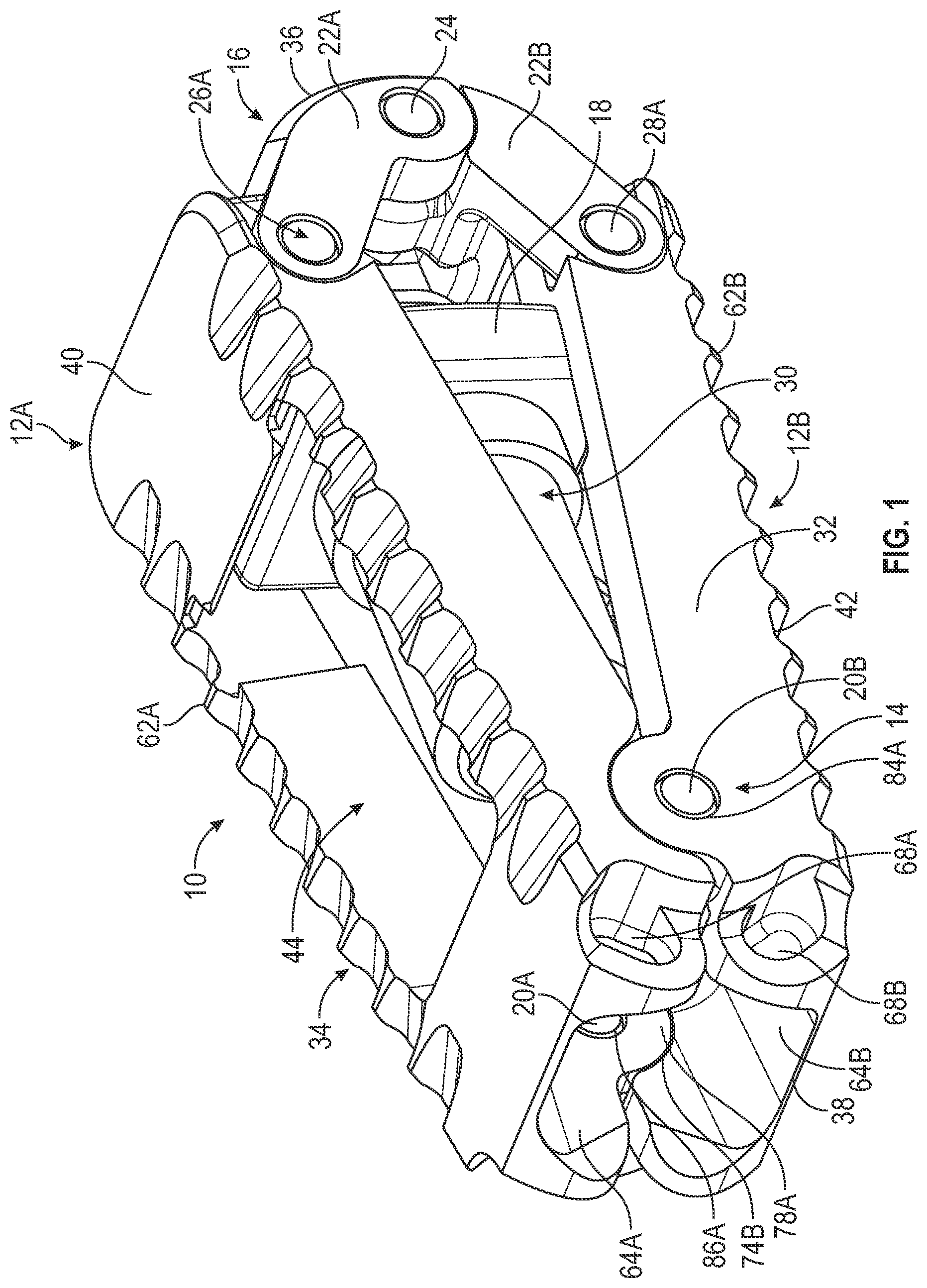
is a perspective view of an interbody implant of comprising a cage structure pivotable by a wedge and a toggle joint. A is an exploded view of the interbody implant of showing superior and inferior cages of the cage structure and pivot pins. B is an exploded view of the interbody implant of showing the toggle joint and associated pins. C is an exploded view of the interbody implant of showing the wedge and a threaded fastener. A is a side view of the interbody implant of in a collapsed state showing interior surfaces of the superior and inferior cages engaged with each other. B is a side view of the interbody implant of in an expanded state showing interior surfaces of the superior and inferior cages angled relative to each other. is a side view of the interbody implant of B from an opposing viewpoint. is a top view of the interbody implant of B showing the threaded fastener through windows of the cage structure. is an end view of the interbody implant of showing the threaded fastener for the wedge and the toggle joint. is an end view of the interbody implant of showing the toggle joint. A is a side cross-sectional view of the interbody implant of in a substantially collapsed state. B is a side cross-sectional view of the interbody implant between the collapsed state and the expanded state showing the wedge disengaging and the toggle joint engaging. C is a side cross-sectional view of the interbody implant of in a substantially expanded state. is a line diagram illustrating a method of implanting a dual-action expandable intravertebral implant. is a side view of an inserter comprising a handle and an insertion rod coupled to an interbody implant of the present disclosure. A is a perspective view of a pushrod configured for use with the inserter of for high volume dispensing. B is a perspective view of a pushrod configured for use with the inserter of for low volume dispensing. A is a cross-sectional view of the inserter of with the high-volume pushrod inserted therethrough. B is a close-up view of first and second pawls acting on the pushrod of A illustrating a force diagram. is a close-up view of the insertion rod of the inserter of A showing the interbody implant coupled thereto and a surgical material cartridge positioned therein. is a close-up view of the handle of the inserter of A showing a coupling controller, a push mechanism and a locking mechanism. is a perspective view of the push mechanism and the locking mechanism of shown in isolation. A is a perspective view of the locking mechanism of showing a locking pawl and a button. B is a rear view of the locking mechanism of showing the locking pawl selectively engageable with the button. is a perspective view of the push mechanism of engaged with a pushrod. A is a rear perspective view of a high-volume pushrod shown from a proximal-to-distal viewpoint to illustrate opposing tracks of teeth. B is a rear perspective view of a low-volume pushrod shown from a proximal-to-distal viewpoint to illustrate opposing tracks of teeth. A is a rear cross-sectional view of the high-volume pushrod of A loaded into the push mechanism. B is a rear cross-sectional view of the low-volume pushrod of B loaded into the push mechanism. A is a rear perspective view of a distal portion of the insertion rod of engaged with an interbody implant. B is a front perspective view of a distal portion of the insertion rod of disengaged from an interbody implant. C is a distal end view of the insertion rod of showing a coupling arm mated therewith. is a side view of a coupling arm of the insertion rod of A- 20 C showing curvature of the coupling arm. is a side view of the coupling controller of showing a control knob for the coupling arms. is a side view of the coupling controller of with the control knob removed to show a translation cam. is a side view of the coupling controller of with an access cover removed from the translation cam. is side cross-sectional view of the coupling controller of showing engagement of the control knob and the translation cam. In the drawings, which are not necessarily drawn to scale, like numerals may describe similar components in different views. Like numerals having different letter suffixes may represent different instances of similar components. The drawings illustrate generally, by way of example, but not by way of limitation, various embodiments discussed in the present document.
DETAILED DESCRIPTION
is a perspective view of interbody implant 10 of the present application showing superior cage 12 A, inferior cage 12 B, hinge or pivot joint 14 , toggle joint 16 and wedge 18 . A is an exploded view of interbody implant 10 of showing superior cage 12 A and inferior cage 12 B. B is an exploded view of interbody implant 10 of showing toggle joint 16 . C is an exploded view of interbody implant 10 of showing wedge 18 and screw mechanism or drive shaft 30 . A is a side view of interbody implant 10 of in a collapsed state showing interior surfaces of superior and inferior cages 12 A and 12 B engaged with each other. B is a side view of interbody implant 10 of in an expanded state showing interior surfaces of superior and inferior cages 12 A and 12 B angled relative to each other. is a side view of interbody implant 10 of B from an opposing viewpoint of that of B . is a top view of interbody implant 10 of B showing drive shaft 30 through windows 60 A and 60 B of the cage structure. is an end view of interbody implant 10 of showing toggle joint 16 . A is a side cross-sectional view of interbody implant 10 of in a substantially collapsed state. show the various features of implant 10 from different angles, different states of being exploded and different operational states and together show the configuration and operation of implant 10 . are discussed concurrently. Superior cage 12 A and inferior cage 12 B can be connected at pivot joint 14 via pins 20 A and 20 B. Toggle joint 16 can comprise superior linkage 22 A and inferior linkage 22 B, which can be connected to each other via pin 24 . Superior linkage 22 A can be connected to superior cage 12 A via pin 26 A and pin 28 A ( B ). Inferior linkage 22 B can be connected in inferior cage 12 B via pin 26 B and pin 28 B ( B ). Wedge 18 can be configured to interact with superior cage 12 A, inferior cage 12 B and toggle joint 16 via drive shaft 30 . Interbody implant 10 can comprise side surface 32 , side surface 34 , insertion portion 36 , coupling portion 38 , superior surface 40 and inferior surface 42 . With reference to C , the present application shows and describes a particular orientation of interbody implant 10 . However, other orientations can be used. For example, coupling portion 38 and insertion portion 36 can be on either the anterior or posterior side of the spinal column; e.g., interbody implant 10 can be rotated one-hundred-eighty degrees in the plane of A and 3 B . Likewise, superior surface 40 and inferior surface 42 can be reversed so superior surface 40 point downward an inferior surface points upward, e.g., interbody implant 10 can be rotated one-hundred-eighty degrees in the plane of . Additionally, side surfaces 32 and 34 can be used in opposite directions. Interbody implant 10 can be shaped for positioning between adjacent anatomic bodies, such as adjacent vertebrae in a spinal column. Interbody implant can be configured to occupy space where a degenerative or damaged disk has been removed. As such, interbody implant 10 can be configured to directly contact bone, particularly at superior surface 40 and inferior surface 42 . For example, superior surface 40 can contact the inferior surface of an upper vertebra and inferior surface 42 can contact the superior surface of a lower vertebra. Interbody implant 10 can be configured to promote bone in-growth into the surfaces of interbody implant 10 by inclusion of space between superior cage 12 A and inferior cage 12 B, and elsewhere, that can form internal cavity 44 , which can provide a space for holding bone graft or other bone-growth-promoting materials to promote in-growth of bone from the adjacent vertebrae. As is discussed in greater detail below with reference to A and 3 B , interbody implant 10 can be collapsed to the configuration of A to facilitate insertion into anatomy of a patient, such as through an incision and in between adjacent bones, and then expanded to the configuration of B when positioned in the desired location to, for example, influence the relative position of the adjacent bone. As is discussed in greater detail with reference to A- 8 C , drive shaft 30 can be operated to change interbody implant 10 between the expanded configuration of B and the collapsed position of A , and vice versa, in a staged or staggered manner to utilize the different mechanical advantages of wedge 18 and toggle joint 16 . Superior cage 12 A can comprise first leg 50 A, second leg 52 A, insertion end 54 A and coupler end 56 A. Inferior cage 14 B can comprise first leg 50 B, second leg 52 B, insertion end 54 B and coupler end 56 B. Legs 50 A and 52 A and ends 54 A and 56 A can be configured to define superior surface 40 and surround window 60 A. Legs 50 B and 52 B and ends 54 B and 56 BA can be configured to define inferior surface 42 and surround window 60 B. Superior cage 12 A can further comprise scallops 62 A, portal 64 A, portal 66 A ( A ) and couplers 68 A and 70 A ( ). Inferior cage 12 B can further comprise scallops 62 B, portal 64 B, portal 66 B ( A ) and couplers 68 B and 70 B ( ). Superior cage 12 A can comprise outer hinge pockets 72 A and 74 A ( ) and inner hinges 76 A and 78 A ( ). Inferior cage 12 B can include inner hinge pockets 72 B and 74 B and outer hinges 76 B and 78 B. Superior cage 12 A can comprise toggle pockets 80 A and 82 A and inferior cage 12 B can comprise toggle pockets 80 B and 82 B. Legs 50 A- 52 B can include comprise elongate bodies configured to extend in anterior-posterior directions and provide structural stability to implant 10 . Scallops 62 A and 62 B can be provided on legs 50 A- 52 B to provide engagement with soft tissue and bone, such as when implant 10 is in an expanded state. Legs 50 A and 52 A can be connected by insertion end 54 A and coupler end 56 A to form portal 64 A. Superior surface 40 and inferior surface 42 can include flat or planar portions to allow implant to slide along soft tissue or bone, such as when implant 10 is in a collapsed state. Portals 64 A and 64 B can extend into the superior and inferior surfaces of implant 10 to form a superior-inferior path through implant 10 , thereby allowing bone-growth through implant 10 . Portals 64 A and 64 B and 66 A and 66 B can cooperate to form a medial-lateral passage through implant 10 . Portals 66 A and 66 B can provide space for operation of toggle joint 16 . Portals 64 A and 64 B can provide space for an instrument to reach drive shaft 30 for wedge 18 . Portals 64 A and 64 B can also provide access to internal cavity 44 for the placement of bone graft material, bone cement or the like. Couplers 68 A- 70 B can form sockets for coupling to a tool, such as a four-pin insertion device (e.g., inserter 600 of ) having four circular pins or pads (e.g., couplers 816 A, 816 B, 818 A, 818 B of B ) that can engage couplers 68 A- 78 B. Couplers 68 A- 70 B can have an arcuate shape to allow for articulation of superior cage 12 A and inferior cage 12 B while remaining engaged with the four pins of the insertion device. Thus, the pads or pins of the insertion device can be circular and have a diameter that is equal to the width of the slots forming couplers 68 A- 70 A, but the slots can be longer to allow the pads or pins to slide in the slots. The pads or pins can be mounted to spring-loaded detents to allow for engagement with couplers 68 A- 70 B, but that prevent relative rotation between the insertion device and implant 10 . Thus, the insertion device can be used to push implant 10 between anatomy and position implant 10 in the desired location. Superior cage 12 A and inferior cage 12 B can be similarly constructed except for the locations of pockets 72 A and 74 A and pockets 72 B and 74 B. Pockets 72 A and 74 A of superior cage 12 A can be configured to be exposed to the exterior of implant 10 , while flanges 76 B and 78 B of inferior cage 12 B can be configured to be exposed to the exterior of implant 10 . Conversely, pockets 72 B and 74 B of inferior cage 12 B can be configured to be exposed to the interior of implant 10 , while flanges 76 A and 78 A of superior cage 12 A can be configured to be exposed to the interior of implant 10 . As such, flanges 76 A and 78 A of superior cage 12 A can nest within flanges 76 B and 78 B of inferior cage 12 B. Pin bores 84 A and 86 A can align with pin bores 84 B and 86 B to receive pins 20 A and 20 B, respectively. As such, superior cage 12 A and inferior cage 12 B can pivot relative to each other at pivot joint 14 . Toggle pockets 80 A- 82 B can cooperate to receive linkages 22 A and 22 B. Toggle pockets 80 A- 82 B can include pin bores 86 A and 86 B and 88 A ( A ) and 88 B ( A ), respectively, to receive pins 26 A, 28 A, 26 B and 28 B. Superior linkage 22 A can comprise first link, 90 A, second link 92 A, crosspiece 94 A, first cam 96 A, second cam 98 A and pin holes 100 A, 102 A, 104 A and 106 A. Inferior linkage 22 B can comprise first link, 90 B, second link 92 B, crosspiece 94 B, first cam 96 B, second cam 98 B and pin holes 100 B, 102 B, 104 B and 106 B. Link 90 A can be positioned in pocket 80 A, link 92 A can be positioned in pocket 82 A, link 90 B can be positioned in pocket 80 B and link 92 B can be positioned in pocket 82 B. Superior linkage 22 A and inferior linkage 22 B can be configured to have the same shape, but are used in opposite orientations. As such, pin holes 104 A, 106 B, 104 B and 106 A can align to receive pin 24 . Leg 90 A and cam 96 A can be offset from each other and leg 92 A and cam 98 A can be offset from each other such that linkage 22 A has a curved shape. Leg 90 B and cam 96 B can be offset from each other and leg 92 B and cam 98 B can be offset from each other such that linkage 22 B has a curved shape. Likewise, crosspieces 94 A and 94 B can be curved in a corresponding manner. Thus, linkages 22 A and 22 B can be tucked between cages 12 A and 12 B in the collapsed state to provide a low profile. Additionally, the curvature of linkages 22 A and 22 B give insertion portion 36 implant 10 a pointed shape in the collapsed state as can be seen in A and a rounded shape in the expanded state as can be seen in B . Drive shaft 30 can comprise first shaft 110 and second shaft 112 . Wedge 18 can comprise body 114 , socket 116 , slide surface 118 , side surfaces 120 A and 120 B, and stops 122 A- 122 D. First shaft 110 can comprise shaft 124 , interior passage 126 , flange 128 and drive socket 130 . In various examples, such as those of A- 8 C , flange 128 can be omitted. Second shaft 112 can comprise shaft 132 , threaded exterior 134 , coupler 136 and pin hole 138 . In an example, interior passage 126 and threaded exterior 134 can be threadedly engaged with each other in similar fashion as the fastener known as a binding post. Wedge 18 can be positioned on first shaft 110 such that socket 116 abuts flange 128 . In the illustration of C , socket 116 of wedge 18 can comprise a throughbore and the exterior of shaft 124 can be smooth so that first shaft 110 can rotate within wedge 18 . However, in additional examples, as shown in A- 8 C , socket 116 and the exterior of shaft 124 can be mated in a threaded engagement. In such a configuration, drive shaft 30 can be configured to provide dual-action advancement of wedge 18 relative to toggle joint 16 . For example, wedge 18 can ride on the exterior of shaft 124 of first shaft 110 in a threaded engagement and threaded exterior 134 of second shaft 112 can ride in threading of interior passage 126 of first shaft 110 . As such, rotation of first shaft 110 at socket 130 via a driver instrument can cause advancement of wedge 18 in a compound fashion. Thus, as discussed with reference to A- 8 C , a driver instrument can be inserted into socket 130 to rotate first shaft 110 , thereby causing wedge 18 to move closer to second shaft 112 (providing the wedge action) and advancing second shaft 112 into interior passage 126 (facilitating operation of toggle joint 16 ). Both of these actions bring wedge 18 closer to coupler 136 , which ultimately allows toggle joint 16 to operate, such as when stops 122 A- 122 D of wedge 18 engage stop surfaces 142 A and 142 B of cages 12 A and 12 B. The orientation between superior surface 40 and inferior surface 42 can be selected and set such that angle α can correspond to a desired wedge angle (e.g., lordosis) between adjacent vertebrae. For example, interbody implant 10 depicted in C can be configured for use in the lower lumbar region of the spine between any of the L1-L5 vertebrae. In a particular example, interbody implant 10 can be used between the L4 and L5 vertebrae or the L5 and S1 vertebrae where the wedge angle can be in the range of about 6 degrees to about 10 degrees. However, in other embodiments, interbody implant 10 can be configured for use in other regions of a spinal column and can be configured such that superior surface 40 and inferior surface 42 are approximately parallel. Furthermore, intervertebral implants according to the present disclosure can be configured for insertion into the spine at different levels and at different insertion approaches, e.g., anterior or posterior, and with angle α being in the range of approximately fifteen to thirty-five degrees. A- 8 C show cross-sectional views of implant 10 transitioning from a collapsed state to an expanded state via engagement of first and second expansion mechanisms, such as wedge 18 and toggle joint 16 . A- 8 C are taken at section 8 - 8 of , with drive shaft 30 additionally being shown in cross-section. A is a side cross-sectional view of interbody implant 10 of in the collapsed state. Drive shaft 30 can be retracted so that superior cage 12 A and inferior cage 12 B are engaged with each other, as shown in A , at interface 144 . Also shown in A is distance D, which is the distance between pins 26 A and 26 B when the interior surfaces of cages 12 A and 12 B are in contact with each other and parallel. Drive shaft 30 can be operated so that wedge 18 engages surfaces of superior cage 12 A and inferior cage 12 B such that wedge 18 causes cages 12 A and 12 B to spread apart and pivot relative to each other at pin 20 B. In particular, surfaces 118 A and 118 B of wedge 18 can engage angled surfaces 140 A and 140 B. As first shaft 110 is rotated, wedge 18 can be pushed into angled surfaces 140 A and 140 B to force superior cage 12 A and inferior cage 12 B away from each other. Drive shaft 30 can advance wedge 18 twice as fast as the threaded engagement between wedge 18 and first shaft 110 would allow due to the compound threading action arising from second shaft 112 also being threaded into first shaft 110 . Thus, wedge 18 can be used to provide the initial angulation between cages 12 A and 12 B when it is most difficult to displace anatomy. B is a side cross-sectional view of interbody implant 10 between the collapsed state and the expanded stage showing wedge 18 disengaging angled surfaces 140 A and 140 B and toggle joint 16 beginning to engage. Wedge 18 can advance toward stop surfaces 142 A and 142 B along angled surfaces 140 A and 140 B due to the square outer shape of wedge 18 being prevented from rotation vias surfaces of cages 12 A and 12 B, thereby allowing the threading engagement to translate wedge 18 . In the example of C , instead of wedge 18 being driven along shaft 124 via threaded engagement, wedge 18 can be pulled along by threaded engagement between interior passage 126 and threaded exterior 134 due to flange 128 . Wedge 18 can reach the end of angled surfaces 140 A and 140 B to reach engagement with stop surfaces 142 A and 142 B. Thus, further outward expansion of cages 12 A and 12 B via wedge 18 can cease and toggle joint 16 can takeover. C is a side cross-sectional view of interbody implant 10 of in the expanded state. Engagement of wedge 18 with stop surfaces 142 A and 142 B can initiate operation of toggle joint 16 . As drive shaft 30 continues to be rotated by a driver instrument, wedge 18 can pull pin 24 closer to wedge 18 . Furthermore, wedge 18 advances closer to the end (to the right in C ) of first shaft 110 as second shaft 112 is pulled further inside of first shaft 110 due to the compound threading action mentioned above. Thus, toggle joint 16 can take over from wedge 18 in providing pivoting action to cages 12 A and 12 B. Toggle joint 16 can be more readily expanded after the initial expansion provided by wedge 18 to take advantage of the greater height of toggle joint 16 . Specifically, linkages 22 A and 22 B when rotated away from each other on pin 24 are taller than wedge 18 . Described another way, it can be more difficult to expand toggle joint 16 from the collapsed state when under load from anatomy due to the enhanced force being applied to linkages 22 A and 22 B due to lever effects of the anatomy. Thus, wedge 18 and toggle joint 16 work cooperatively and sequentially to take advantage of the mechanical benefits of each expansion mechanism. is a line diagram illustrating method 500 of implanting dual-action expandable intravertebral implant 10 . Interbody implant 10 can be implanted between adjacent bones, such as adjacent vertebrae, to promote bone in-growth. A method of implanting interbody implant 10 can include properly preparing and performing an incision in a patient to access a medial, lateral or posterior portion of a spine adjacent an area where damaged or diseased intervertebral tissue is located. Soft tissue can be retracted using appropriate instrumentation to provide better access to the damaged or diseased intervertebral tissue. The damaged or diseased intervertebral tissue can be removed using appropriate methods to clear access to inferior and superior bone surfaces of the adjacent vertebrae. At step 502 , expandable intervertebral implant 10 can be attached to an inserter (e.g., inserter 600 of ) in a collapsed state so as to minimize the height of intervertebral implant 10 . The inserter can be attached to couplers 68 A- 70 B. At step 504 , the inserter can be used to insert intervertebral implant 10 into the incision and between adjacent vertebrae, where damaged or diseased tissue has been removed. For example, an elongate inserter can be coupled to couplers 68 A- 70 B to push implant 20 through the incision and to the target location. The inserter can be used to position implant 10 into the desired implant position. In other examples, interbody implant 10 can be attached to a tool, such as by threading a shaft of an insertion instrument into engagement with interbody implant 10 . Interbody implant 10 can be manipulated by a surgeon, robot or another person to position insertion portion 36 in the incision. Interbody implant 10 can be oriented in a desired direction such that insertion portion 36 is pointed toward the anterior of the spine and coupling portion 38 is pointed toward the posterior of the spine, for example. Crosspieces 94 A and 94 B can be engaged with soft tissue that is located medially or laterally of the implantation site in the spine. The insertion tool can be pushed to slide soft tissue across legs 50 A- 52 B. The curvature of crosspieces 94 A and 94 B can push the soft tissue out of the way of interbody implant 10 to inhibit soft tissue from scraping along scallops 62 A and 62 B. The insertion tool can be pushed until legs 50 A- 52 B engage the exposed superior and inferior bone surfaces of the adjacent vertebrae where disc material has been removed. Legs 50 A- 52 B can be pushed in between the adjacent vertebrae and can act as a wedge to initially spread the vertebrae to receive the full thickness of interbody implant 10 after expansion as described below with respect to steps 506 - 520 . Interbody implant 10 can continue to be pushed until scallops 62 A and 62 B are positioned adjacent the exposed superior and inferior bone surfaces of the adjacent vertebrae. Scallops 62 A and 62 B can help engage with bone when implant 10 is finally positioned to prevent displacement by digging into boney structure. Interbody implant 10 can be positioned so as to be centered in the anterior-posterior direction on the vertebrae. If deemed desirable by the surgeon to verify placement of interbody implant 10 , a surgeon can obtain imaging of the patient so that the location of implant 10 relative to the medial and lateral sides of the vertebrae can be viewed and measured. At step 506 , a driver can be extended into intervertebral implant 10 , such as by being passed into and through the inserter. As step 508 , first stage expansion of intervertebral implant 10 can be commenced with implant 10 in the desired location. At step 510 , the driver can be inserted into drive shaft 30 to activate the first stage expansion. The driver can be engaged with drive socket 130 to rotate interior passage 126 and threaded exterior 134 relative to each other. Likewise, wedge 18 and shaft 124 can be rotated relative to each other. At step 512 , wedge 18 can be slid along angled surfaces 140 A and 140 B to push superior cage 12 A and inferior cage 12 B away from each other. At step 514 , wedge 18 can be configured to be advanced to engage stop surfaces 142 A and 142 B. Thus, wedge 18 can be prevented from further providing direct outward expansion of superior cage 12 A and inferior cage 12 B. At step 516 , the driver can continue to rotate drive shaft 30 to activate the second stage expansion. Stop surfaces 142 A and 142 B can be configured to allow wedge 18 facilitate operation of toggle joint 16 . At step 518 , toggle joint 16 can be engaged by drive shaft 30 being pulled through wedge 18 to draw pin 24 closer to wedge 18 , thereby causing linkages 22 A And 22 B to rotate at pin 24 to cause outward expansion of cages 12 A and 12 B proximate insertion portion 36 , lifting cages 12 A and 12 B outward away from wedge 18 . At step 520 , implant 10 can be expanded to the desired angle. In particular, angle α can be adjusted to meet the needs of a specific patient, such as a particular lordosis angle based on the level of the spine that implant 10 is inserted into. At step 522 , the driver for drive shaft 30 can be detached from implant 10 and withdrawn from the anatomy. At step 524 , the inserter can be detached from implant 10 and withdrawn from the anatomy. At step 526 , bone cement or bone graft material can be positioned within implant 10 . For example, bone-growth-promoting material can be packed into windows 60 A and 60 B. In various examples, bone-growth-promoting material can be packed into windows 60 A and 60 B before implantation. However, in some embodiments described herein, bone-growth-promoting material can be packed after implantation. In other examples, bone graft material can be inserted into implant 10 before step 524 . At step 528 , the incision in the patient can be appropriately closed to leave interbody implant 10 within the patient to allow implant 10 to fuse the adjacent vertebrae through, via, bone in-growth. With interbody implant 10 positioned between bone surfaces of the adjacent vertebrae, bone from the vertebrae can grow into the windows 60 A and 60 B to interact with the bone graft material placed therein. The bone-growth-promoting material located within windows 60 A and 60 B can interact with the vertebrae to enhance bone growth. Furthermore, movement of the vertebrae, such as by bending and twisting of the spine, can apply compression to interbody implant 10 . Compressive forces applied to interbody implant 10 in the superior-inferior direction by the spine can be transmitted the bone-growth-promoting material to thereby stimulate biological growth of bone at the vertebrae contacting interbody implant 10 . As bone grows into interbody implant 10 , the superior and inferior vertebrae can become fused together through interbody implant 10 . Interbody implant 10 of the present disclosure can be configured for use in various spinal correction procedures. Intervertebral implants of the present disclosure can be used with different insertion approaches and for various levels of the spine. Specifically, the illustrated example can be used as a Transformational Lumbar Interbody Fusion (TLIF) device or a Posterior Lumbar Interbody Fusion (PLIF) device. However, the features and benefits of the present disclosure can additionally be configured for use as an anatomic Anterior Cervical Interbody Fusion (ACIF) device or a lordotic Anterior Cervical Interbody Fusion (ACIF) device. TLIF devices can be configured for insertion in between vertebrae from a posterior side of the spinal column. More specifically, a TLIF device of the present disclosure can be configured for insertion into a spinal column between a spinous process and an adjacent transverse process. A TLIF device of the present disclosure can be configured, e.g., with different thicknesses, sizes, widths, lengths to accommodate usage at different levels in the spinal column or in different sized patients. A TLIF device of the present application can be rotated on a superior-inferior axis in a transverse plane while being inserted to the position TLIF device to extend across the spinal column. An insertion device can be coupled to coupling portion 38 and insertion portion 36 can be pushed through tissue into the spinal column such that superior and inferior surfaces 40 and 42 align with an inferior surface of a superior vertebra and a superior surface of an inferior vertebra. PLIF devices can be configured for insertion in between vertebrae from a posterior side of the spinal column. More specifically, a PLIF device of the present disclosure can be configured for insertion into a spinal column between a spinous process and an adjacent transverse process. A PLIF device of the present disclosure can be configured, e.g., with different thicknesses, sizes, widths, lengths to accommodate usage at different levels in the spinal column or in different sized patients. A PLIF device of the present disclosure can inserted straight into the spinal column on one side of the spinal cord. In examples, a second PLIF device can be inserted straight into the spinal column on the opposite side of the spinal column. An insertion device can be coupled to coupling portion 38 and insertion portion 36 can be pushed through tissue into the spinal column such that superior and inferior surfaces 40 and 42 align with an inferior surface of a superior vertebra and a superior surface of an inferior vertebra. The systems, devices and methods discussed in the present application can be useful in implanting expandable interbody implants, such as those that can be used in spinal correction procedures involving lateral, transverse, anterior or posterior insertion of a spacer between adjacent vertebrae. The interbody implant can have first and second bodies that can be coupled to each other at a pivoting coupling. The angle between the first and second bodies can be adjusted to push adjacent anatomy into a desired orientation, such as a desired angle therebetween. The first and second bodies can be moved into the desired angle using two expansion mechanisms that can provide different actuation qualities, such as expansion strength or force, expansion height and mechanical leverage. Thus, the two expansion mechanisms can be arranged in conjunction with an actuation mechanism to sequentially operate to pivot the first and second bodies relative to each other to overcome resistance from the anatomy and position the anatomy in the desired orientation. The first expansion mechanism can be configured to overcome high initial loading on the implant from the anatomy. The second expansion mechanism can be configured to provide increased expansion beyond the configuration of the first expansion mechanism when initial loading from the anatomy is overcome. is a side view of inserter 600 comprising handle 602 and insertion rod 604 coupled to interbody implant 10 of the present disclosure. Handle 602 can comprise body 606 , cover 608 , trigger 610 , handpiece 612 , spring 614 , access port 616 and lock button 618 . Insertion rod 604 can comprise coupling controller 620 , shaft 622 and first coupling arm 624 A. Body 606 can comprising a housing be used to hold a mechanism (e.g., push mechanism 652 of A ) for moving a pushrod (e.g., pushrod 630 of A or pushrod 631 of B ) through inserter 600 to dispense a material into implant 10 . Coupling controller 620 can be operated to couple and uncouple implant 10 to the distal end of shaft 622 . Trigger 610 can be pivotably coupled to body 606 and cover 608 at pin 625 . Handle 602 and trigger 610 can be configured to be held by a user to dispense a surgical material, such as a material that promotes bone growth, an artificial bone graft material or a natural bone graft material. Squeezing of trigger 610 toward handle 602 can cause movement of a piston in shaft 622 to push material out of a cartridge (e.g., cartridge 656 of ) loaded into shaft 622 and into implant 10 . Button 618 can be operated to change a rate at which material is dispensed from inserter 600 in combination with the use of different pushrods, as shown in A and 11 B . A is a perspective view of pushrod 630 configured for use with inserter 600 of . Pushrod 630 can comprise knob 632 and shaft 634 , which can comprise engagement portion 636 and piston portion 638 . A top or superior side (as illustrated) of engagement portion 636 can comprise tooth track 640 A and groove 642 A. As can be seen in A , a bottom or inferior side of engagement portion 636 can comprise tooth track 640 B and groove 642 B. As is discussed with reference to , 19 A and 19 B , pushrod 630 can be configured to interact with push mechanism 652 ( ) in only one way to cause dispensing at a first rate. However, other pushrods can be configured to interact with push mechanism 652 in different ways to cause dispensing at different rates. B is a perspective view of pushrod 631 configured for use with inserter 600 of . Pushrod 631 can comprise knob 633 and shaft 635 , which can comprise engagement portion 637 and piston portion 639 . A top or superior side (as illustrated) of engagement portion 637 can comprise tooth track 641 A and groove 643 A. As can be seen in B , a bottom or inferior side of engagement portion 637 can comprise tooth track 641 B and groove 643 B. As is discussed with reference to , 19 A and 19 B , pushrod 631 can be configured to interact with push mechanism 652 ( A ) in only one way to cause dispensing at a second rate that is different than the first rate. A is a cross-sectional view of inserter 600 of with pushrod 630 inserted therethrough. Inserter 600 can comprise locking mechanism 650 , push mechanism 652 and coupling controller 620 . Shaft 622 of insertion rod 604 can comprise internal lumen 654 through which pushrod 630 can extend and in which cartridge 656 can be positioned. Distal end 658 of insertion rod 604 can couple to implant 10 . A proximal portion of insertion rod 604 can be connected to access port 616 . Access port 616 can be aligned with lumen 654 to allow passage of pushrod 630 from a proximal side of body 606 through to implant 10 . Trigger 610 can be used to actuate push mechanism 652 to advance pushrod 630 into lumen 654 in a controlled manner and with a requisite level of force to expel material from cartridge 656 . Spring 614 can be used to bias trigger 610 away from handle 612 . As discussed in greater detail below, different pushrods can be loaded into push mechanism 652 to cause advancement by push mechanism 652 at different rates. Locking mechanism 650 can be used to selectively prevent movement of pushrod 630 . Coupling controller 620 can facilitate coupling and coupling of implant 10 from insertion rod 604 from a proximal end of shaft 622 . As discussed in greater detail below, rotation of coupling controller 620 can cause deflection of coupling arm 624 A and coupling arm 624 B ( B ) to facilitate coupling and uncoupling of implant 10 . B is a close-up view of first and second pawls 672 A and 672 B acting on pushrod 630 of A . B illustrates forces F 2 and F 3 acting on pushrod 630 , which are discussed in greater detail below. is a close-up view of insertion rod 604 of inserter 600 of A showing interbody implant 10 and bone graft material cartridge 656 . Cartridge 656 can be loaded into distal end 658 of shaft 622 after implant 10 has been inserted into the anatomy and adjusted (e.g., expanded) to the desired configuration. Shaft 622 should be empty to allow for insertion of a tool (e.g., screwdriver) to expand implant 10 . Cartridge 656 can be filled with bone graft material and can be clipped to the tip of a pushrod (e.g., pushrod 630 ). The assembly of cartridge 656 and pushrod 630 can be inserted by access port 616 after step 520 of . Shaft 622 can include pads 660 A and 660 B to center cartridge 656 within lumen 654 and prevent cartridge 656 from passing out of lumen 654 . (See B .) Pads 660 A and 660 B can be located can be located near distal end 658 in order to position cartridge 656 proximate implant 10 . As such, advancement of shaft 634 via push mechanism 652 into cartridge 656 can cause bone graft material to enter implant 10 such as through portals 64 A and 64 B ( ). is a close-up view of body 606 of inserter 600 of A showing coupling controller 620 , push mechanism 652 and locking mechanism 650 . is a perspective view of push mechanism 620 and locking mechanism 650 of shown in isolation. are discussed concurrently. Coupling controller 620 can comprise knob 662 , piston 664 , cover 666 and pins 668 A and 668 B. Shaft 622 can comprise first channel 670 A and second channel 670 B into which coupling arms 624 A and 624 B can be positioned, respectively. Push mechanism 652 can comprise first pawl 672 A, second pawl 672 B, first pivot pin 674 A, second pivot pin 674 B, first biasing element 676 A, second biasing element 676 B, first bias pin 678 A and second bias pin 678 B. Locking mechanism 650 can comprise pin 682 , biasing element 684 , button 618 and locking pawl 688 . Locking pawl 688 can further comprise tang 691 and latch 693 . As shown in , first pawl 672 A can comprise first body 690 A comprising groove 692 A, pin bore 694 A, rail 696 A and prong 698 A; and second pawl 672 B can comprise second body 690 B comprising groove 692 B, pin bore 694 B, rail 696 B and prong 698 B. Operation of locking mechanism 650 is described with reference to A and 16 B . Operation of push mechanism 652 is described with reference to B . Operation of coupling controller 620 is described with reference to A- 25 . A is a perspective view of locking mechanism 650 of showing locking pawl 680 positioned relative to button 618 . B is a rear view of locking mechanism 650 of . A and 16 B are discussed concurrently. Button 618 can comprise body 686 comprising first and second pads 700 A and 700 B, and pawl window 702 comprising lock surface 704 A with notch 706 A and dispense surface 704 B with notch 706 B. Body 686 can be positioned in body 606 ( ) such that pads 700 A and 700 B extend through corresponding sockets in body 606 and cover 608 . As such, button 618 can be accessible on the exterior of body 606 to a user of inserter 600 . Body 686 can fit into the corresponding sockets via an interference fit that allows sliding. Body 686 can be prevented from separating from body 606 via the presence of locking pawl 680 . Locking pawl 680 can be mounted to body 606 via pin 682 , which can be fit into corresponding bores in body 606 and cover 608 . Locking pawl 680 can comprise cylinder portions 708 A and 708 B that can include sockets for receiving pin 682 . Slot 710 can be positioned between cylinder portions 708 A and 708 B to allow for the presence of biasing device 712 . Biasing device 712 can comprise a torsion spring having a wire wound into a coil that can be disposed on pin 682 and ends of the wire extended therefrom. Locking pawl 688 can further comprise tang 691 and latch 693 . As such, one arm of biasing device 712 can press against a component of inserter 600 (e.g., see access port 616 of ) and another arm of biasing device 712 can press against latch 693 . Thus, latch 693 can be biased into pawl window 702 against one of lock surface 704 A and dispense surface 704 B, depending on the position of body 686 . Bulge 714 of latch 693 can seat into one of notches 706 A and 706 B to inhibit lateral translation of button 618 . Lock surface 704 A can be further below pin 682 than dispense surface 704 B, which allows tang 691 to be positioned higher when latch 693 is engaged with lock surface 704 A as compared to dispense surface 704 B, to engage pushrod 630 ( A ) to prevent movement of pushrod 630 . As described below, pushrod 630 can comprise teeth that receive tang 691 . Dispense surface 704 B can be closer to pin 682 than lock surface 704 A, which allows tang 691 to be positioned lower when latch 693 is engaged with dispense surface 704 B as compared to lock surface 704 A, to disengage pushrod 630 ( A ) and allow pushrod 630 to move. is a perspective view of push mechanism 652 of engaged with pushrod 630 . First pawl 672 A can be mounted to trigger 610 via pin 674 A and second pawl 672 B can be mounted to trigger 610 via pin 674 B. Pawls 672 A and 672 B can be rotatably mounted to pawl pins 674 A and 674 B. Pins 678 A and 678 B can be mounted to trigger 610 outward of pins 674 A and 674 B relative to pushrod 630 . Biasing elements 676 A and 676 B can be mounted to pins 678 A and 678 B to bias first and second pawls 672 A and 672 B inward toward pushrod 630 , respectively. Biasing elements 676 A and 676 B can comprise torsion springs having wires wound into coils that can be disposed on pins 678 A and 678 B and ends of the wires extended therefrom. Thus, both of pawls 672 A and 672 B will contact pushrod 630 , but only one will functionally engage pushrod 630 depending on the configuration of pushrod 630 and other pushrods. Specifically, both of rails 696 A and 696 B and prongs 698 A and 698 B will be biased toward pushrod 630 , but only one of rails 696 A and 696 B from one of pawls 672 A and 672 B and one of prongs 698 A and 698 B from the other of pawls 672 A and 672 B engage the pushrod. As shown in A and 19 B , one of rails 696 A and 696 B will engage one of grooves 642 A and 642 B to allow engagement of one of prongs 698 A and 698 B with one of teeth 640 A and 640 B to allow movement of pushrod 230 , while the other of rails 696 A and 669 B will engage the other of teeth 640 A and 640 B to prevent engagement of the other of prongs 698 A and 698 B with the other of teeth 640 A and 640 B to prevent movement of pushrod 230 . A is a rear perspective view of high-volume pushrod 230 of showing opposing tracks of teeth 640 A and 640 B adjacent channels 642 A and 642 B. Pushrod 230 can have a circular cross-sectional profile with first surface 720 A and second surface 720 B forming flats extending along the length of pushrod 230 . First surface 720 A and second surface 720 B can comprise surfaces into which teeth 640 A and 640 B and channels 642 A and 642 B can be formed, respectively. Channels 642 A and 642 B are located on opposing diagonal corners of pushrod 230 . Likewise, teeth 640 A and 640 B are located on opposing diagonal corners of pushrod 230 . As such, whether first surface 720 A is oriented upward (superior) or second surface 720 B is oriented upward (superior), the top of pushrod 230 will always have either teeth 640 A or 640 B on the right (as shown in A ) and either channels 642 A and 642 B on the left (as shown in A ). Thus, as can be seen in A , the upward facing teeth will always engage with prong 698 A and the upward facing channel will always receive rail 696 A (without contact between rail 696 A and the channel). Conversely, as can be seen in A , the downward facing teeth will always engage with rail 696 B and the downward facing channel will always face prong 698 B (without contact between prong 696 B and the teeth). Thus, only first pawl 672 A will engage with pushrod 230 as configured in the illustration of A . B is a rear perspective view of low-volume pushrod 231 configured to engage a different portion of the push mechanism 652 than high-volume pushrod 230 . Low-volume pushrod 231 can comprise opposing tracks of teeth 641 A and 641 B adjacent channels 643 A and 643 B. Pushrod 231 can have a circular cross-sectional profile with first surface 721 A and second surface 721 B forming flats extending along the length of pushrod 231 . First surface 721 A and second surface 721 B can comprise surfaces into which teeth 641 A and 641 B and channels 643 A and 643 B can be formed, respectively. Channels 643 A and 643 B are located on opposing diagonal corners of pushrod 231 . Likewise, teeth 641 A and 641 B are located on opposing diagonal corners of pushrod 231 . As such, whether first surface 721 A is oriented upward (superior) or second surface 721 B is oriented upward (superior), the top of pushrod 231 will always have either teeth 641 A or 641 B on the left (as shown in B ) and either channels 643 A and 643 B on the right (as shown in B ). Thus, as can be seen in B , the downward facing teeth will always engage with prong 698 B and the downward facing channel will always receive rail 696 B (without contact between rail 696 B and the channel). Conversely, as can be seen in B , the upward facing teeth will always engage with rail 696 A and the upward facing channel will always face prong 698 A (without contact between prong 696 A and the teeth). Thus, only second pawl 672 B will engage with pushrod 231 as configured in the illustration of B . A is a rear cross-sectional view of high-volume pushrod 230 of A loaded into push mechanism 652 . B is a rear cross-sectional view of low-volume pushrod 231 of B loaded into push mechanism 652 . Trigger 610 is configured to rotate about trigger axis AT of pin 625 . As shown in A , pawl 672 A is configured to rotate about high-speed axis AH of pin 674 A. As shown in B , pawl 672 B is configured to rotate about low-speed axis AL of pin 674 B. High-speed axis AH is further away from trigger axis AT than low-speed axis AL. As such, rotation of trigger 610 can cause pawl 672 A to be moved with a higher velocity and lower force than pawl 672 B. Thus, pawl 672 A can cause a push rod configured to engage with pawl 672 A (e.g., pushrod 230 ) faster and with less force than pawl 672 B can cause a pushrod configured to engage with pawl 672 B (e.g., pushrod 231 ) to move. As shown in A , pawls 672 A and 672 B and trigger 610 can generate forces F 1 , F 2 and F 3 about pin 625 , as summarized in Equations 1-4. {right arrow over ( F 1 )}× AB ={right arrow over ( F 2 )}× BC ={right arrow over ( F 3 )}× BD Equation [1] AB>BD>BC Equation [2] {right arrow over ( F 2 )}>{right arrow over ( F 3 )}>{right arrow over ( F 1 )} Equation [3] {right arrow over ( V A )}>{right arrow over ( V D )}>{right arrow over ( V C )} Equation [4] In examples, it can be advantageous to dispense substitute (e.g., artificial) bone graft material at an upper rate than natural bone graft material because artificial material can flow easier than biological bone graft material. A is a rear perspective view of a distal portion of insertion rod 604 of engaged with interbody implant 10 . Insertion rod 604 can comprise central lumen 654 , first channel 670 A and second channel 670 B. First coupling arm 624 A can be disposed in first channel 670 A and second coupling arm 624 B can be disposed in second channel 670 B. First channel 670 A can comprise base 802 A and overhanging flanges 804 A and 806 A. Second channel 670 B can comprise base 802 B and overhanging flanges 804 B and 806 B. First coupling arm 624 A can comprise body 808 A and flanges 810 A and 812 A, thereby giving first coupling arm 624 A a T-shaped cross-section. Second coupling arm 624 B can comprise body 808 B and flanges 810 B and 812 B, thereby giving second coupling arm 624 B a T-shaped cross-section. However, first coupling arm 624 A and second coupling arm 624 B can additionally include flat regions 814 A and 814 B where body 808 A and body 808 B are tapered down to the height of flanges 810 A- 812 B. Coupling arms 624 A and 624 B can comprise shanks that slide along bases 802 A and 802 B of channels 670 A and 670 B, respectively. As shown in , coupling arms 624 A and 624 B can include prongs 815 A and 815 B that engage with coupling controller 620 to produce distal and proximal movement of arms 624 A and 624 B. When arms 624 A and 624 B are retracted proximally into channels 670 A and 670 B (such that distal coupling portions (e.g., couplers 816 A- 818 B of B ) are immediately proximate the distal end of shaft 622 ), bodies 808 A and 808 B extend generally parallel with channels 670 A and 670 B, as well as shaft 622 of insertion rod 604 . However, as can be seen in , bodies 808 A and 808 B can have a curvature to bias the distal coupling portions away from shaft 622 . Thus, when coupling controller 620 is operated to push arms 624 A and 624 B distally, the distal coupling portions can move away from each other to open up and receive or release implant 10 , as shown in B . Flat regions 814 A and 814 B can comprised thinned down portions of arms 624 A and 624 B that have rectangular cross-sectional profiles to allow arms 624 A and 624 B a greater ability to flex. B is a front perspective view of a distal portion of insertion rod 604 of disengaged from interbody implant 10 . First coupling arm 624 A and second coupling arm 624 B can be extended out from channels 670 A and 670 B to allow for separation of arms 624 A and 624 B from each other due to, for example, curvature arising from pre-bends in each of arms 624 A and 624 B. First coupling arm 624 A can include couplers 816 A and 818 A, groove 820 A and pad 660 A. Second coupling arm 624 B can include couplers 816 B and 818 B, groove 820 BA and pad 822 B. Couplers 816 A- 818 B can be sized to fit within couplers 68 A- 70 B of implant 10 (See ). Couplers 68 A- 70 B can comprise arcuate slots and couplers 816 A- 818 B can comprise circular pads. The width of the arcuate slots can be slightly larger than the diameter of the circular pads to allow the pads to slide along an arcuate path with the slots. As such, implant 10 can be expanded and contracted while couplers 816 A- 818 B remain engaged with couplers 68 A- 70 B. Grooves 820 A and 820 B can be curved to mate with corresponding curvatures on implant 10 to provide a secure fit between arms 624 A and 624 B and implant 10 . C is a distal end view of insertion rod 604 having coupling arm 624 A mated therewith. Coupling arm 624 A can comprise couplers 816 A and 818 B, groove 820 A and pad 660 A. Coupling arm 624 B can comprise corresponding components as coupling arm 624 A shown in C . Insertion rod 604 can comprise shaft 622 , internal lumen 654 , implant cutout 824 A and pad cutout 826 A. Insertion rod 604 can additionally include a corresponding implant cutout opposing cutout 824 A and a corresponding pad cutout opposing pad cutout 826 A. Cutout 824 A and the opposing cutout can correspond to the shape of grooves 820 A and 820 B to closely conform to the shape of implant 10 . As mentioned, pad 660 A and 660 B ( ) can be used to engage cartridge 656 . is a side view of coupling arm 624 A of insertion rod 604 of A- 20 C showing curvature of body 808 A of coupling arm 624 A. The majority of the length of arm 624 A from prongs 815 A ( ) to the portion shown in can extend straight, parallel to shaft 622 , along axis A 2 . However, the distal most portion of arm 624 A can be curved outward, as shown in , beginning at approximately the location of flat region 814 A to facilitate coupling and uncoupling from implant 10 . The amount of curvature can allow for couplers 816 A- 818 B to disengage from couplers 68 A- 70 B. For example, the amount of curvature can be at least as much as the height of couplers 816 A- 818 B, plus an additional amount to allow for removal from couplers 68 A- 70 B. is a side view of coupling controller 620 of showing control knob 662 for coupling arms 624 A and 624 B. Coupling controller 620 can comprise knob 662 , piston 664 , cover 666 and pins 668 A and 668 B. Shaft 622 can comprise first channel 680 A and second channel 670 B. Shaft 622 can extend from body 606 at base 830 . Shaft 622 can be stationary relative to body 606 . Piston 664 can be slidably mounted to shaft 622 to move distally and proximally. Shaft 622 can comprise flat side 832 , as well as an opposite flat side (not visible), along which piston 664 can slide. Flat side 832 and the opposing flat side prevent rotation of piston 664 about the axis of shaft 662 . Knob 662 can be rotatably coupled with piston 664 such that rotation of knob 662 can cause proximal or distal translation of piston 664 along shaft 622 . is a side view of coupling controller 620 of with control knob 662 removed to show piston 664 . Pins 668 A and 668 B can be used to anchor knob 662 to shaft 622 so that knob 662 is prevented from translating along shaft 622 . As can be seen in , knob 662 can include flange 846 that engages lip 848 of base 830 to prevent distal translation of knob 662 . Pins 668 A and 668 B can prevent proximal translation of knob 662 . However, pins 668 A and 668 B can be removed to facilitate disassembly of inserter 600 . Piston 664 can include threading 834 that meshes with mating threading 836 ( ) on interior of bore 838 of knob 662 . As such, rotation of knob 662 about the axis of shaft 622 can push or pull piston 664 via engagement of threading 834 and 836 . Piston 664 can include cover 666 to allow access to ends of arms 624 A and 624 B where prongs 815 A and 815 B are located. is a side view of coupling controller 620 of with access cover 666 removed from piston 664 to show springs 840 A and 840 B and balls 842 A and 842 , which can be used to bias cover 666 in place within piston 664 . Seal 844 can additionally be placed between piston 664 and knob 662 to, for example, prevent disassembly of piston 664 from knob 662 . Cover 666 can include lip 850 configured to be positioned distally of prongs 815 A and 815 B. Thus, when cover 666 is seated within window 852 of piston 664 , lip 850 can prevent distal movement of arms 624 A and 624 B. However, when cover 666 is removed, arms 624 A and 624 B can be withdrawn from piston 664 in a distal direction along channels 670 A and 670 B. As such, to assemble inserter 600 , knob 622 can be placed over shaft 622 so flange 846 engages lip 848 . Base 830 can be assembled with body 606 . Pins 668 A and 668 B can be inserted to secure knob 622 . Piston 664 can be assembled to knob 622 via rotation of knob 622 to thread ably engage with piston 664 . Arms 624 A and 624 B can then be inserted into channels 670 A and 670 B until prongs 815 A and 815 B are visible in window 852 . Cover 666 can then be placed in window 852 to secure arms 624 A and 624 B. is side cross-sectional view of coupling controller 620 of showing engagement of control knob 622 and piston 664 . As shown, threading 836 of knob 622 can engage threading of piston 624 . Thus, knob 622 can be rotated in a fixed axial position about shaft 622 to cause pushing of piston 624 via the threaded engagement. Piston 624 can be prevented from rotation by engagement with flat sides 832 of shaft 622 . Translation of piston 624 can cause a corresponding translation of arms 624 A and 624 B via engagement with prongs 815 A and 815 B. Various Notes & Examples Example 1 is an intervertebral implant comprising: a first cage; a second cage; a hinge connecting the first cage and the second cage at a first side of the intervertebral implant; a toggle joint connecting the first cage and the second cage at a second side of the intervertebral implant; and a wedge positioned between the first cage and the second cage and configured to translate from proximate the first side toward the second side to cause rotation about the hinge and initial expansion of the toggle joint. In Example 2, the subject matter of Example 1 optionally includes wherein: the first cage comprises a first angled surface; and the second cage comprises a second angled surface opposing the first angled surface; wherein the wedge translates along the first and second angled surfaces to push the first and second cages away from each other. In Example 3, the subject matter of Example 2 optionally includes a first stop surface extending inward from the first angled surface; and a second stop surface extending inward from the second angled surface; wherein the first and second stop surfaces are configured to inhibit further translation of the wedge along the first and second angled surfaces. In Example 4, the subject matter of any one or more of Examples 1-3 optionally include wherein: the intervertebral implant is configured to rotate from a collapsed position to an expanded position; in the collapsed position the first cage and the second cage are within ten degrees of parallel; and in the expanded position the first cage and the second cage are angled relative to each other in a range of twenty-five to thirty-five degrees. In Example 5, the subject matter of any one or more of Examples 1-4 optionally include wherein the wedge is accessible between the first cage and the second cage from the first side. In Example 6, the subject matter of Example 5 optionally includes a screw mechanism configured to transition the expandable implant between an expanded position and a collapsed position, the screw mechanism comprising: a shaft having an outer threaded surface along which the wedge translates; a socket located at a first end of the shaft; and a pivot connected to the toggle joint at a second end. In Example 7, the subject matter of Example 6 optionally includes wherein the shaft comprises: a first component comprising the outer threaded surface and the socket; and a second component threaded into the first component and including the pivot. In Example 8, the subject matter of any one or more of Examples 1-7 optionally include wherein the toggle joint comprises: a first linkage extending from the first cage; and a second linkage extending from the second cage; and a pin coupling the first and second linkages. In Example 9, the subject matter of Example 8 optionally includes wherein the first and second linkages are curved. In Example 10, the subject matter of Example 9 optionally includes wherein: The toggle joint forms a rounded tip at the second side of the intervertebral implant in an expanded configuration; and the toggle joint forms a pointed tip at the second side of the intervertebral implant in a collapsed position. In Example 11, the subject matter of any one or more of Examples 1-10 optionally include a plurality of arcuate slots located proximate the first side configured to couple to an inserter in a collapsed configuration and an expanded configuration. Example 12 is a method of implanting an intervertebral implant, the method comprising: inserting the intervertebral implant into anatomy of a patient, the intervertebral implant comprising a first component rotatably coupled to a second component at a pivot point; operating a first expansion mechanism to rotate the intervertebral implant at the pivot point to expand the intervertebral implant to a first level; and operating a second expansion mechanism to rotate the intervertebral implant at the pivot point from the first level to a second level. In Example 13, the subject matter of Example 12 optionally includes wherein operating the first expansion mechanism comprises: sliding a wedge along angled surfaces of the first and second components. In Example 14, the subject matter of any one or more of Examples 12-13 optionally include wherein operating the second expansion mechanism comprises: expanding a toggle joint. In Example 15, the subject matter of any one or more of Examples 12-14 optionally include wherein operating the first expansion mechanism and operating the second expansion mechanism comprise rotating a threaded fastener. In Example 16, the subject matter of Example 15 optionally includes wherein rotating a threaded fastener comprises sequentially engaging the first expansion mechanism and then the second expansion mechanism. In Example 17, the subject matter of any one or more of Examples 12-16 optionally include wherein inserting the intervertebral implant into anatomy of a patient comprises inserting the intervertebral implant into a spinal column such that the first component faces an inferior surface of a first vertebra and the second component faces a superior surface of a second vertebra adjacent the first vertebra. Example 18 is a two-stage intervertebral implant comprising: an expandable cage comprising: an upper body; a lower body; and a pivot connecting the upper body and the lower body; a first expansion mechanism configured to pivot the upper body and the lower body at the pivot point in a first stage; and a second expansion mechanism configured to pivot the upper body and the lower body at the pivot point in a second stage beyond the first stage. In Example 19, the subject matter of Example 18 optionally includes an actuation mechanism configured to sequentially operate the first expansion mechanism and the second expansion mechanism. In Example 20, the subject matter of Example 19 optionally includes wherein: the first expansion mechanism comprises a wedge configured to slide against the upper body and the lower body to push apart the upper body and the lower body; the second expansion mechanism comprises a toggle joint configured to expand between the upper body and the lower body to push apart the upper body and the lower body; and the actuation mechanism comprises: a binding post fastener connected to the toggle joint; and a wedge threaded onto the binding post fastener and engaged with the upper and lower bodies. Example 21 is an inserter device for a prosthetic implant, the inserter device comprising: an elongate rod extending from a proximal end to a distal end, the elongate rod comprising: an internal lumen extending between the proximal end and the distal end; and a first channel extending along an exterior of the elongate rod between the proximal end and the distal end; a first coupling arm comprising: an elongate shank configured to ride in the first channel; a distal coupling portion including a coupling feature configured for coupling to the prosthetic implant; and a proximal actuation portion; and an actuation mechanism coupled to a proximal end of the elongate rod and configured to move the first coupling arm within the first channel between a retracted position and an advanced position. In Example 22, the subject matter of Example 21 optionally includes wherein elongate shank includes a pre-bend configured to bias the distal coupling portion away from the elongate rod. In Example 23, the subject matter of Example 22 optionally includes wherein: the elongate shank is positioned such that the distal coupling portion extends out of the first channel such that: in the retracted position the distal coupling portion axially aligns with the first channel; and in the advanced position the distal coupling portion is displaced from the channel. In Example 24, the subject matter of any one or more of Examples 21-23 optionally include wherein: the first channel comprises: a base extending along the elongate rod; and a pair of flanges overhanging the base; and the elongate shank is configured to slide along the base opposing the pair of flanges. In Example 25, the subject matter of Example 24 optionally includes wherein the elongate shank comprises a T-shaped cross-section. In Example 26, the subject matter of Example 25 optionally includes wherein the elongate shank comprises a segment proximal of the distal coupling portion comprising a rectangular cross-sectional profile. In Example 27, the subject matter of any one or more of Examples 21-26 optionally include wherein the distal coupling portion comprises a pair of spaced apart tabs. In Example 28, the subject matter of any one or more of Examples 21-27 optionally include wherein the actuation mechanism comprises: a knob rotatable about the elongate rod to push and pull the first coupling arm. In Example 29, the subject matter of Example 28 optionally includes wherein the actuation mechanism further comprises: a piston configured to slide along the elongate rod in a non-rotatable fashion, the piston coupled to the first coupling arm; wherein the knob and the piston are disposed in threaded engagement such that rotation of the knob pushes and pulls the piston. In Example 30, the subject matter of any one or more of Examples 21-29 optionally include a second coupling arm extending in a second channel of the elongate rod. Example 31 is a push mechanism for dispensing a material from a handheld dispenser with a piston, the push mechanism comprising: a trigger configured to rotate about a pivot point; a first pawl configured to rotate on the trigger a first distance from the pivot point; and a second pawl configured to rotate on the trigger a second distance from the pivot point, wherein the second pawl is positioned relative to the first pawl to form a channel therebetween for pushing the piston in a longitudinal direction; wherein the first pawl and the second pawl are oppositely configured to interact with the channel. In Example 32, the subject matter of Example 31 optionally includes wherein the first pawl and the second pawl are positioned above the pivot point. In Example 33, the subject matter of any one or more of Examples 31-32 optionally include wherein: the first pawl faces toward the pivot point; and the second pawl faces away from the pivot point. In Example 34, the subject matter of Example 33 optionally includes a first pushrod configured to engage with the first pawl; and a second pushrod configured to engage with the second pawl. In Example 35, the subject matter of Example 34 optionally includes wherein the first pawl comprises: a first tang extending in the longitudinal direction; and a first rail extending alongside the first tang. In Example 36, the subject matter of Example 35 optionally includes wherein the first pushrod comprises: a first tooth track comprising a plurality of positions configured to engage with the first tang; and a first channel configured to receive the first rail. In Example 37, the subject matter of Example 36 optionally includes wherein the first pushrod comprises an opposite tooth track positioned diagonally across a cross-section of the first pushrod; and an opposite channel positioned diagonally across the cross-section of the first pushrod. In Example 38, the subject matter of any one or more of Examples 34-37 optionally include wherein the second pawl comprises: a second tang extending in the longitudinal direction; and a second rail extending alongside the second tang. In Example 39, the subject matter of Example 38 optionally includes wherein the second pushrod comprises: a second tooth track comprising a plurality of positions configured to engage with the second tan, and a second channel configured to receive the second rail. In Example 40, the subject matter of any one or more of Examples 33-39 optionally include wherein the first pawl and the second pawl are biased toward the channel. Each of these non-limiting examples can stand on its own, or can be combined in various permutations or combinations with one or more of the other examples. The above detailed description includes references to the accompanying drawings, which form a part of the detailed description. The drawings show, by way of illustration, specific embodiments in which the invention can be practiced. These embodiments are also referred to herein as “examples.” Such examples can include elements in addition to those shown or described. However, the present inventor also contemplates examples in which only those elements shown or described are provided. Moreover, the present inventor also contemplates examples using any combination or permutation of those elements shown or described (or one or more aspects thereof), either with respect to a particular example (or one or more aspects thereof), or with respect to other examples (or one or more aspects thereof) shown or described herein. In the event of inconsistent usages between this document and any documents so incorporated by reference, the usage in this document controls. In this document, the terms “a” or “an” are used, as is common in patent documents, to include one or more than one, independent of any other instances or usages of “at least one” or “one or more.” In this document, the term “or” is used to refer to a nonexclusive or, such that “A or B” includes “A but not B,” “B but not A,” and “A and B,” unless otherwise indicated. In this document, the terms “including” and “in which” are used as the plain-English equivalents of the respective terms “comprising” and “wherein.” Also, in the following claims, the terms “including” and “comprising” are open-ended, that is, a system, device, article, composition, formulation, or process that includes elements in addition to those listed after such a term in a claim are still deemed to fall within the scope of that claim. Moreover, in the following claims, the terms “first,” “second,” and “third,” etc. are used merely as labels, and are not intended to impose numerical requirements on their objects. The above description is intended to be illustrative, and not restrictive. For example, the above-described examples (or one or more aspects thereof) may be used in combination with each other. Other embodiments can be used, such as by one of ordinary skill in the art upon reviewing the above description. The Abstract is provided to comply with 37 C.F.R. § 1.72(b), to allow the reader to quickly ascertain the nature of the technical disclosure. It is submitted with the understanding that it will not be used to interpret or limit the scope or meaning of the claims. Also, in the above Detailed Description, various features may be grouped together to streamline the disclosure. This should not be interpreted as intending that an unclaimed disclosed feature is essential to any claim. Rather, inventive subject matter may lie in less than all features of a particular disclosed embodiment. Thus, the following claims are hereby incorporated into the Detailed Description as examples or embodiments, with each claim standing on its own as a separate embodiment, and it is contemplated that such embodiments can be combined with each other in various combinations or permutations. The scope of the invention should be determined with reference to the appended claims, along with the full scope of equivalents to which such claims are entitled.
Figures (20)
Citations
This patent cites (13)
- US10561502
- US10624756
- US10631996
- US2007/0282441
- US2014/0114420
- US2015/0148908
- US2016/0166396
- US2016/0331542
- US2016/0354212
- US2017/0112630
- US2020/0054461
- US2020/0129307
- US2020/0360151