Formation Process for a Potassium-ion Hybrid Super-capacitor
Abstract
A process may form a potassium-ion hybrid super-capacitor. Such a process may include: charging a potassium-ion hybrid supercapacitor including (i) a negative electrode comprising graphite, (ii) a positive electrode comprising activated carbon, and (ii) an electrolyte comprising a potassium salt, at constant current in a protocol of between Cx/50 and Cx/2, to a charge cutoff voltage of between 3.0 V and 3.3 V; holding the supercapacitor at the charge cutoff voltage until the leakage current is between Cx/2000 and Cx/500; and discharging the supercapacitor at constant current in a protocol of between Cx/50 and Cx, to a discharge cutoff voltage of between 0 V and 2 V, wherein the process further includes degassing the supercapacitor after the charging, the holding, or the discharging.
Claims (20)
1 . Formation-A process for forming a potassium-ion hybrid super-capacitor, the process comprising: charging the potassium-ion hybrid supercapacitor comprising (i) a negative electrode comprising graphite, (ii) a positive electrode comprising activated carbon, and (iii) an electrolyte comprising a potassium salt, at constant current in a protocol-range of from Cy/10 to 5C y /2, to a charge cutoff voltage in a range of from 3.0 to 3.3 V, C, being a formation capacity of an intercalation compound KC 8 , holding the potassium-ion hybrid supercapacitor at the charge cutoff voltage until a leakage current is in a range of from C y /400 to C y /100, discharging the potassium-ion hybrid supercapacitor at constant current in a range of from C y /10 to 5C y , to a discharge cutoff voltage in a range of from 0 to 2 V; and, degassing the supercapacitor after the charging, the holding, or the discharging.
Show 19 dependent claims
2 . The process of claim 1 , wherein the charging the holding, and/or the discharging is implemented at a temperature in a range of from 15° C. to 30° C.
3 . The process of to claim 2 , wherein each of the charging, the holding, and the discharging are implemented at a temperature in a range of from 15° C. to 30° C.
4 . The process of claim 1 , wherein the charging and the discharging are carried out in a protocol range of from C y /3 to C y .
5 . The process of claim 4 , wherein the charging and the discharging are carried out at C y /2.
6 . The process of claim 1 , wherein the hold time the holding is in a range of from 20 to 28 hours.
7 . The process of claim 6 , wherein the hold time in the holding is 24 hours.
8 . The process of claim 1 , wherein the leakage current at the end of the discharging is C y /200.
9 . The process of claim 1 , wherein the degassing of the supercapacitor is carried out after the discharging.
10 . The process of claim 1 , wherein the electrolyte is non-aqueous.
11 . The process of claim 1 , wherein the potassium salt present in the electrolyte is in solution comprising an organic solvent.
12 . The process of claim 1 , wherein the potassium salt present in the electrolyte comprises KClO 4 , KBF 4 , KPF 6 , potassium bis(trifluoromethanesulfonyl)imide, potassium bis(fluorosulfonyl)imide, potassium bis(oxalato) borate, KSCN, KSbF 6 , KAsF 6 , KAICl 4 , KSiF 6 , and/or KSO 3 CF 3 .
13 . The process of claim 12 , wherein the potassium salt present in the electrolyte comprises KClO 4 , KBF 4 , and/or KPF 6 .
14 . The process of claim 12 , wherein the potassium salt is in solution comprising a carbonate, linear ether, nitrile, lactone, and/or amide solvents.
15 . The process of claim 14 , wherein the solvent comprises propylene carbonate, ethylene carbonate, diethyl carbonate, dimethyl carbonate, dimethoxyethane, acetonitrile, γ-butyrolactone, and/or dimethylformamide.
16 . The process of claim 1 , wherein the charging, the holding, and/or the discharging is implemented at a temperature in a range of from 15 to 30° C., and wherein the charging and the discharging are carried out in a range of from C y /3 to C y .
17 . The process of claim 1 , wherein each of the charging, the holding, and the discharging are implemented at a temperature in a range of from 15 to 30° C., and wherein the charging and the discharging are carried out in a range of from C y /3 to C y .
18 . The process of claim 1 , wherein the potassium salt present in the electrolyte comprises KClO 4 .
19 . The process of claim 1 , wherein the potassium salt present in the electrolyte comprises KBF 4 .
20 . The process of claim 1 , wherein the potassium salt present in the electrolyte comprises KPF 6 .
Full Description
Show full text →
CROSS-REFERENCE TO RELATED APPLICATIONS
The present application is the claims the benefit of the filing date of French Appl. No. 21 09574, filed on Sep. 13, 2021, the content of each of which is incorporated by reference.
TECHNICAL FIELD
The present invention relates to a formation process for a potassium-ion hybrid supercapacitor.
PRIOR ART
The power density and energy density supplied by supercapacitors, as energy storage devices, are midway between those supplied by electrochemical batteries and by conventional electrolytic capacitors. Supercapacitors also return energy more rapidly than an electrochemical battery. In known symmetrical supercapacitors, the positive and negative electrodes are based on activated carbon and the electrolyte is based on tetraethylammonium tetrafluoro-borate (TEABF 4 ). These symmetrical supercapacitors have a high power density and high cyclability but a low energy density, associated with the medium capacity of the supercapacitor (which is of the order of 8 Wh/kg) and with the operating voltage. To meet the demand for an increase in energy density, supercapacitors were developed that lie between the symmetrical supercapacitors conventionally used, based on activated carbon, and batteries. Such capacitors are referred to as asymmetric or hybrid. One of the electrodes—conventionally, the negative electrode—is specifically formed from a rechargeable battery material, and the other—conventionally, the positive electrode—is formed on the basis of activated carbon, and the electrolyte situated between these two electrodes is conventionally aqueous and generally comprises lithium salts in solution. Charge storage in a hybrid supercapacitor takes place at the negative electrode via a redox reaction, whereas charge storage at the positive electrode takes place via the formation of an electrochemical double layer. Patent application FR 3 005 199 A1 describes an example of a hybrid supercapacitor said to be a potassium-ion supercapacitor, comprising a negative electrode comprising graphite, a positive electrode comprising activated carbon, and an electrolyte comprising at least one potassium salt. The first usage cycles, referred to as “formation” cycles, of an electrochemical system such as a hybrid supercapacitor are essential in ensuring effective long-term operation of the supercapacitor. The reference formation used to date, corresponding to 5 charge/discharge cycles at C x or 5C y (where C x and C y , respectively, are the formation capacity of the intercalation compound KC 8 and the capacity of the cell) from 0.5 to 3.5 V, gives rise to scatter and to instability in the cycling performance, with discharged capacities that reduce and then increase drastically in several thousand cycles, to reach values very much greater than the symmetrical supercapacitors. Applications WO 2016/168496 A1, WO 2016/059907 A1, CN 106797022 A, US 2018/254524 A1 and DE 10 2018 105613 A1 describe electrode formulations and electrolyte compositions for functional systems based on potassium, such as potassium-ion batteries, and potassium-ion hybrid capacitors and even supercapacitors, albeit without specifying the formation step for the electrodes. Application WO 2020/125560 A1 describes a preliminary potassiation step which comprises using potassium metal in order to produce a passivation layer of potassium on the surface of the negative electrode, which comprises graphite. Exposition of the Invention There is therefore a need for enhancing the stability and the reproducibility of the cycling performance of potassium-ion supercapacitors in a manner which should be simple and inexpensive to implement.
SUMMARY OF THE INVENTION
The subject of the invention is therefore a formation process for a potassium-ion hybrid supercapacitor, the process comprising: a) supplying the potassium-ion hybrid supercapacitor comprising: a negative electrode comprising graphite, a positive electrode comprising activated carbon, an electrolyte comprising at least one potassium salt, b) charging the supercapacitor at constant current in a protocol of between C x /50 and C x /2 or between C y /10 and 2.5C y , to a charge cutoff voltage of between 3.0 V and 3.3 V, where C x is the formation capacity of the intercalation compound KC 8 and C y is the capacity of the electrolytic cell, c) holding the supercapacitor at the charge cutoff voltage until the leakage current is between C x /2000 and C x /500, d) discharging the supercapacitor at constant current in a protocol of between C x /50 and C x or between C y /10 and 5C y , to a discharge cutoff voltage of between 0 V and 2 V, preferably equal to 0.5 V, where the process further comprises degassing the supercapacitor after one of steps b) to d). Holding a supercapacitor under direct voltage is commonly used for keeping it in the charged state, by compensating the self-discharge phenomena, and therefore for simulating its ageing and observing the drop in its cycling performance. Surprisingly, and contrary to all expectations, the inventors have found that holding the supercapacitor under direct voltage by means of the process according to the invention enables cycling performance to be obtained which is reproducible and stable, especially in the long term, with high energy densities, in particular, of greater than 12 Wh/kg electrochemical core . The process according to the invention is, moreover, a low-cost process which is easy to implement, with a limited number of steps. Furthermore, it does not require a complex step of preliminary potassiation as described in the prior art. The positive electrode is the site of the formation of the electrochemical double layer. The negative electrode is the site of a redox reaction which involves intercalation of the potassium present in the electrolyte. For example, the intercalation may take place such that the potassium composition is at most equal to KC 8 , for example, ranging from KC 64 to KC 8 and advantageously corresponding to KC 48 or to KC 16 . The formation capacity of the intercalation compound KC 8 , referred to as C x , is equal to 5 times the capacity of the electrolytic cell C y . The electrolytic cell comprises the negative electrode, the positive electrode and the electrolyte. The voltage of the potassium-ion hybrid supercapacitor of step a) may be between 50 mV and 500 mV, preferably between 100 mV and 300 mV. The charge cutoff voltage of step b) is preferably between 3.1 V and 3.3 V, being for example 3.2 V. The time in step c) for which the supercapacitor is held at the charge cutoff voltage is preferably between 22 hours and 26 hours, and for example is 24 hours. At least one and preferably all of steps b) to d) may be implemented at a temperature of between 15° C. and 30° C., preferably between 20° C. and 25° C., better still between 21° C. and 24° C., for example at a temperature of 23° C. It is possible thereby to implement the process according to the invention without a step of heating the potassium-ion hybrid supercapacitor. The charging in step b) may be carried out in a protocol of between C x /15 and C x /5 or between C y /3 and C y , preferably in a C x /10 or C y /2 protocol. The discharging in step d) may be carried out in a protocol of between C x /15 and C x /5 or between C y /3 and C y , preferably in a C x /10 or C y /2 protocol. The hold time in step c) may be between 15 hours and 30 hours, or even between 20 hours and 28 hours, in particular 24 hours. The leakage current at the end of step c) may be between C x /2000 and C x /500 or between C y /400 and C y /100, and is preferably equal to C x /1000 or C y /200. Degassing Degassing is the removal of some or all of the gas or gases present within the potassium-ion hybrid supercapacitor. These one or more gases may have been produced in step b), c) and/or d). They may be electrochemical reaction products associated with the formation of a passivation layer on the negative electrode and/or with secondary reactions between the electrolyte and the functional groups of the positive electrode. The degassing step limits premature ageing of the supercapacitor. It is able in particular to prevent the pores of the electrode being filled with gas and becoming non-functional, the consequence of which would be a sharp drop in performance of the supercapacitor. The degassing of the supercapacitor may be carried out after each of steps b) to d). In particular, the degassing of the supercapacitor may be carried out after step d). Positive Electrode The positive electrode is preferably a capacitive electrode. The positive electrode is preferably porous. Negative Electrode The graphite of the negative electrode is preferably capable of intercalating potassium. It may in particular comprise particulate graphite having a median particle size of 50 μm, this particle size being measured by D50 laser particle size analysis. The potassium therefore has the capacity for intercalation into the graphite of the negative electrode, at high charge states, such that the composition corresponds at most to KC 8 . Electrolyte The electrolyte is preferably non-aqueous. The at least one potassium salt present in the electrolyte may be in solution in at least one organic solvent. The at least one potassium salt may be selected from KClO 4 , KBF 4 , KPF 6 , potassium bis(trifluoromethane-sulfonyl)imide (known by the abbreviation KTFSI), potassium bis(fluorosulfonyl)imide (known by the abbreviation KFSI), potassium bis(oxalato)borate (known by the abbreviation KBOB), KSCN, KSbF 6 , KAsF 6 , KAlCl 4 , KSiF 6 , KSO 3 CF 3 and mixtures thereof, and preferably selected from KClO 4 , KBF 4 , KPF 6 and mixtures thereof. The at least one potassium salt present in the electrolyte may be in solution in at least one solvent selected from carbonate solvents, linear ether solvents, nitrile solvents, lactone solvents, amide solvents and mixtures thereof, and preferably selected from propylene carbonate, ethylene carbonate, diethyl carbonate, dimethyl carbonate, dimethoxyethane, acetonitrile, γ-butyrolactone, dimethylformamide and mixtures thereof.
BRIEF DESCRIPTION OF THE DRAWINGS
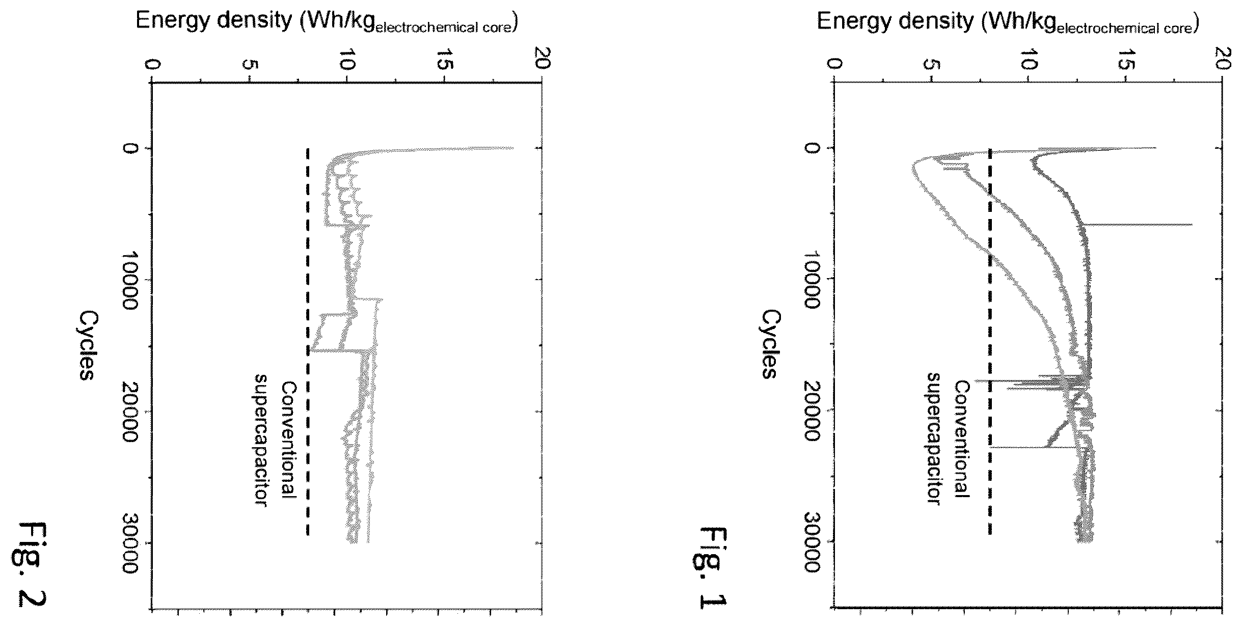
The invention may be appreciated more fully from a reading of the detailed description hereinafter of implementation examples which are not limiting on said invention, and from examination of the appended drawing, in which: shows cycling performance results for a potassium-ion hybrid supercapacitor which has undergone a formation process outside of the invention, shows cycling performance results for a potassium-ion hybrid supercapacitor which has undergone another formation process outside of the invention, shows cycling performance results for a potassium-ion hybrid supercapacitor which has undergone a formation process according to the invention, and shows results of comparative tests evaluating the effect of each step of the process according to the invention.
DETAILED DESCRIPTION
to 4 show cycling performance results for a potassium-ion hybrid supercapacitor which has undergone a formation process outside of or according to the invention. The curves represent the energy density measured as a function of the number of cycles. In these tests, cycling is performed in a 20C x or 100C y protocol. shows the cycling performance results of three potassium-ion hybrid supercapacitors which have undergone the same reference formation process outside of the invention. In these tests, the reference formation process used corresponds to five charge/discharge cycles at C x or 5C y from 0.5 to 3.5 V. It is seen in that the three curves give rise to scattering and to instability of the cycling performance, with energy densities which decrease and then increase drastically in several thousand cycles to reach energy density values of between 12 and 13 Wh/kg electrochemical core , these being values which are very much greater than those obtained with the symmetrical—also called conventional—supercapacitors, which are of the order of 8 Wh/kg electrochemical core . shows the cycling performance results for three potassium-ion hybrid supercapacitors which have undergone the same formation process outside of the invention, consisting of first cycles performed in a C x /10 or C y /2 protocol and at a temperature of approximately 23° C. It is seen in that the curves are reproducible and therefore that the scattering observed in is significantly reduced. The energy density values are nevertheless between 10 and 11 Wh/kg electrochemical core and are lower than the values obtained in . Moreover, the long-term cycling performance of the supercapacitor remains unstable. shows the cycling performance results for four potassium-ion hybrid supercapacitors which have undergone the same implementation example of the formation process according to the invention. In these tests, the implementation example of the formation process according to the invention that is used comprises the succession: of charging the supercapacitor at constant current in a C x /10 or C y /2 protocol to a charge cutoff voltage of 3.2 V, of holding the supercapacitor at the charge cutoff voltage of 3.2 V for a hold time of 24 hours, of discharging the supercapacitor to a discharge cutoff voltage of 0.5 V, and of degassing the supercapacitor. It is seen in that the curves are both reproducible and stable, with high energy density values, of between 12 and 14 Wh/kg electrochemical core . shows the results of comparative tests evaluating the effect of each step of the process according to the invention. The key to is as follows. Curve 1 corresponds to an implementation example of the process according to the invention. Curve 2 corresponds to an implementation example of the process according to the invention without step b). Curve 3 corresponds to an implementation example of the process according to the invention without the degassing. Curve 4 corresponds to an implementation example of the process according to the invention without step b), which is replaced by a step of charging the supercapacitor at constant current in a protocol of more than C x /2 (5 mA), to a charge cutoff voltage of between 3.0 V and 3.3 V. Curve 5 corresponds to an implementation example of the process according to the invention without step c), which is replaced by a step of holding the supercapacitor at the charge cutoff voltage until the leakage current is equal to 10 μA. It is seen in that the best cycling performance, in terms of energy density, stability and reproducibility, is obtained with curve 1, which corresponds to an implementation example of the formation process according to the invention. The tests show, indeed, that the energy density values for curves 2 to 5 do not exceed 12 Wh/kg electrochemical core over the long term. The invention is of course not limited to the implementation example of the process, which is given for the purpose of illustration and is non-limiting.
Figures (2)
Citations
This patent cites (19)
- US6087043
- US2012/0115035
- US2016/0049661
- US2018/0254524
- US2019/0035560
- US2019/0280299
- US2020/0067055
- US2021/0358695
- US106797022
- US111584248
- US10 2018 105 613
- US3 534 443
- US3 848 949
- US3 005 199
- US2020-145061
- USWO 2016/059907
- USWO 2016/168496
- USWO 2018/135627
- USWO 2020/125560