Impact Damping Device for a Rechargeable Battery
Abstract
A power tool, in particular a chipping hammer, having a housing and a battery interface device for releasably connecting at least one rechargeable battery to the power tool. An impact damping device is contained between the housing and the battery interface device, wherein the impact damping device contains at least one damping element which is arranged in a longitudinal extent perpendicularly to a working axis of the power tool.
Claims (19)
1 . A power tool comprising: a housing; a battery interface device for releasably connecting at least one rechargeable battery to the power tool; and a damper device for absorbing and damping impacts acting on the at least one rechargeable battery, the damper contained between the housing and the battery interface device; the damper device having a first hinge and a second hinge and a damper.
19 . A power tool comprising: a housing; a battery interface device for releasably connecting at least one rechargeable battery to the power tool, the battery interface device containing a planar base plate, a first connector for receiving a first rechargeable battery, and a second connector for receiving a second rechargeable battery; and a damper device for absorbing and damping impacts acting on first and second rechargeable batteries, the damper contained between the housing and the battery interface device.
Show 17 dependent claims
2 . The power tool as recited in claim 1 wherein the damper device contains at least one damper arranged in a longitudinal extent perpendicularly to a working axis of the power tool.
3 . The power tool as recited in claim 2 wherein the at least one damper is configured cylindrically with an oval cross-sectional area.
4 . The power tool as recited in claim 2 wherein the at least one damper has at least one axially extending groove on an outer lateral surface.
5 . The power tool as recited in claim 2 wherein the at least one damper at least partially contains an elastic material.
6 . The power tool as recited in claim 2 wherein the at least one damper is configured in the form of a spring element.
7 . The power tool as recited in claim 6 wherein the at least one damper is a coil spring element.
8 . A chipping hammer comprising the power tool as recited in claim 1 .
9 . The power tool as recited in claim 1 wherein the damper device includes at least one damper configured cylindrically with an oval cross-sectional area.
10 . The power tool as recited in claim 1 wherein the damper device includes at least one damper having at least one axially extending groove on an outer lateral surface.
11 . The power tool as recited in claim 1 wherein the damper device includes at least one damper having at least partially an elastic material.
12 . The power tool as recited in claim 1 wherein the damper device includes at least one damper having a spring element.
13 . The power tool as recited in claim 12 wherein the at least one damper is a coil spring element.
14 . The power tool as recited in claim 1 wherein the battery interface device has a first connector for receiving a first rechargeable battery and a second connector for receiving a second rechargeable battery.
15 . The power tool as recited in claim 1 wherein the battery interface device contains a planar base plate.
16 . The power tool as recited in claim 1 wherein the first hinge has a first pin and the second hinge has a second pin.
17 . The power tool as recited in claim 16 wherein the first hinge has a first upper hinge band, a second upper hinge band, and a first lower hinge band, and the second hinge has a third upper hinge band, a fourth upper hinge band, and a second lower hinge band.
18 . The power tool as recited in claim 17 where the first pin is arranged between the first upper hinge band, the second upper hinge band, and the first lower hinge band, and the second pin is arranged between the third upper hinge band, the fourth upper hinge band, and the second lower hinge band.
Full Description
Show full text →
The present invention relates to a power tool, in particular a chipping hammer, having a housing and a battery interface device for releasably connecting at least one rechargeable battery to the power tool.
BACKGROUND
Battery-operated hammer drills and/or chipping hammers of the type mentioned at the beginning are known in principle from the prior art.
SUMMARY OF THE INVENTION
If rechargeable batteries are used to supply the power tool with electrical energy, it is advantageous that particular measures for protecting the rechargeable batteries against impacts, shocks and other mechanical actions are taken. Rechargeable batteries can be quite sensitive, or react in a fault-prone manner to such mechanical actions, such as shocks, impacts, etc., for example. Protective apparatuses known from the prior art for rechargeable batteries on power tools are usually inadequate and/or too complex. It is an object of the present invention to provide a power tool, in particular a chipping hammer, with which the abovementioned problem can be solved and in which the protection of rechargeable batteries connected to the power tool can be improved. The present invention provides a power tool, in particular a chipping hammer, having a housing and a battery interface device for releasably connecting at least one rechargeable battery to the power tool. According to the invention, a damping device for absorbing and damping impacts acting on the at least one rechargeable battery is contained between the housing and the battery interface device. As a result, mechanical actions on the rechargeable battery, for example shocks, impacts, etc., can be reduced and the rechargeable battery protected. The damping device can in this case also be referred to as an impact damping device. Furthermore, the damping device can also be used to reduce vibrations acting on the rechargeable battery. According to a further advantageous embodiment of the present invention, it may be possible that the damping device contains at least one damping element, which is arranged in a longitudinal extent perpendicularly to a working axis of the power tool. According to one advantageous embodiment of the present invention, it may be possible that the damping element is configured in a cylindrical manner and has primarily an oval cross-sectional area. According to a further advantageous embodiment of the present invention, it may be possible that the at least one damping element has at least one axially extending groove on an outer lateral surface. As a result, the elasticity and consequently the damping effect of the damping element can be increased. According to one advantageous embodiment of the present invention, it may be possible that the at least one damping element at least partially contains an elastic material. The elastic material may be an elastomer or rubber. According to a further advantageous embodiment of the present invention, it may be possible that the at least one damping element is configured in the form of a spring element, in particular of a coil spring element. Further advantages will become apparent from the following description of the figures. Various exemplary embodiments of the present invention are illustrated in the figures. The figures, the description and the claims contain numerous features in combination. A person skilled in the art will expediently also consider the features individually and combine them to produce useful further combinations.
BRIEF DESCRIPTION OF THE DRAWINGS
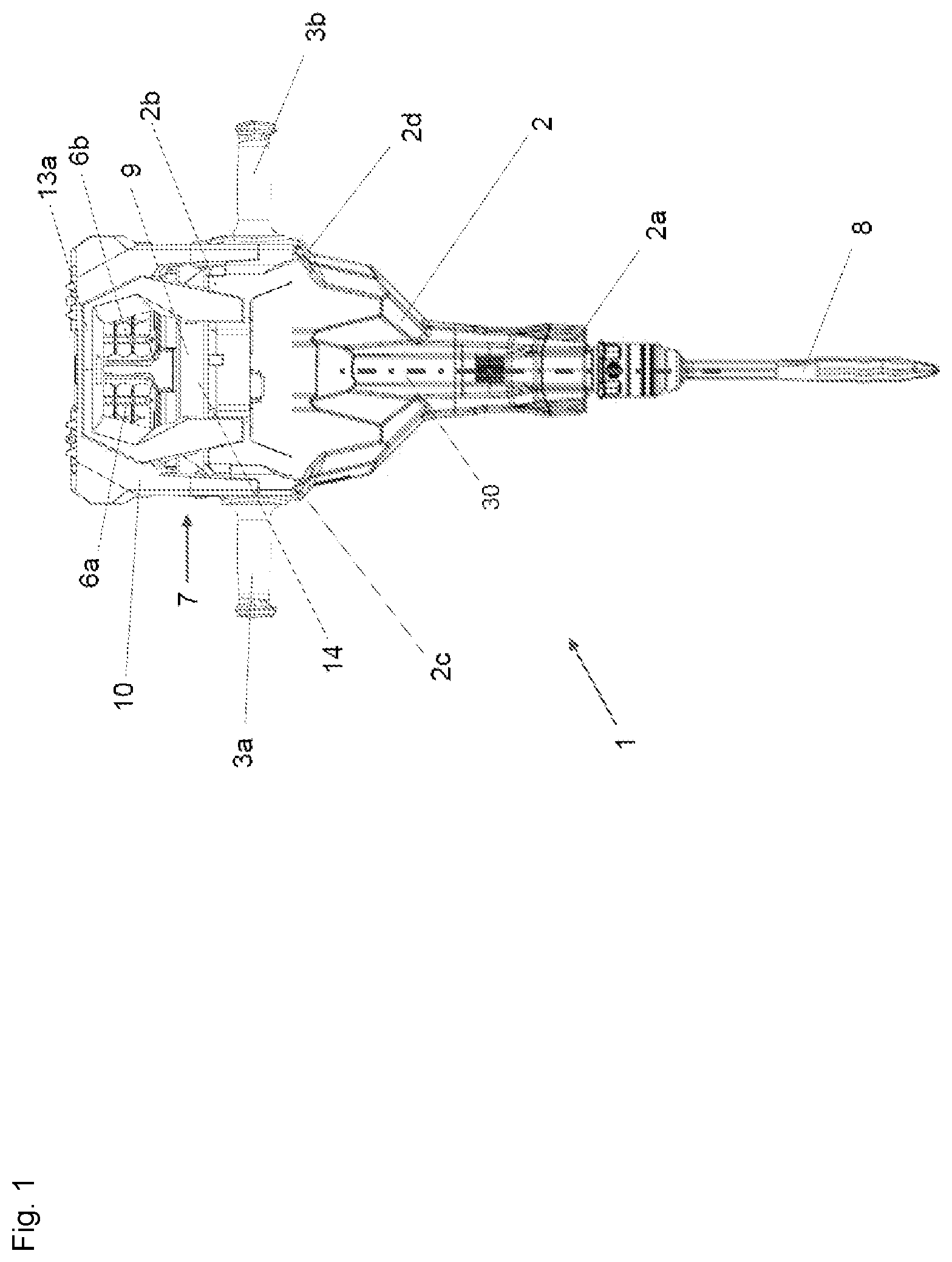
In the figures: shows a side view of a power tool configured as a chipping hammer; shows a side view of an upper end of a housing of the power tool with a guard bracket; shows a side view of the upper end of the housing of the power tool with the guard bracket; shows a perspective view of the upper end of the housing of the power tool with an impact damping device and without the guard bracket; shows a sectional view through the impact damping device; shows a further sectional view through the impact damping device and a first and second rechargeable battery; and shows a perspective view of a damping element.
DETAILED DESCRIPTION
shows a power tool 1 in the form of a chipping hammer. It is also possible, however, for the power tool 1 to be configured in the form of a saw, a grinder, a screwdriver, a drill, a hammer drill or the like. The power tool 1 in the form of a chipping hammer contains primarily a housing 2 , a first handle 3 a , a second handle 3 b , a battery receptacle apparatus 7 , and a tool fitting 5 . Contained inside the housing 2 are primarily an electric motor and an impact apparatus. The impact apparatus can also be referred to as an impact mechanism or impact mechanism apparatus. The electric motor and the impact apparatus are connected together such that pulse-like impacts are generated and transmitted to the tool fitting 5 . To supply the power tool 1 and in particular the electric motor with electrical energy, a first and second rechargeable battery 6 a , 6 b are connected to the power tool 1 via the battery receptacle apparatus 7 . According to an alternative embodiment, it is also possible for only one rechargeable battery or more than two rechargeable batteries to be able to be used. The housing 2 in turn has a first end 2 a , a second end 2 b , a left-hand side wall 2 c and a right-hand side wall 2 d . The first handle 3 a is positioned on the left-hand side wall 2 c and the second handle 3 b is positioned on the right-hand side wall 2 d . The tool fitting 5 is positioned at the first end 2 a of the housing 2 and serves to receive and hold a tool 8 . In the exemplary embodiment that is illustrated in the figures, the tool 8 is configured in the form of a chisel. The battery receptacle apparatus 5 is positioned at the second end 2 b of the housing 2 and serves to receive and hold the first and second rechargeable batteries 6 a , 6 b. The battery receptacle apparatus 7 in turn contains a battery interface device 9 and a battery fall protection device 10 . The battery interface device 9 contains primarily a planar base plate 11 , a first connection device 12 a for receiving the first rechargeable battery 6 a , and a second connection device 12 b for receiving the second rechargeable battery 6 b . The first and second connection devices 12 a , 12 b are positioned on the base plate 11 in the arrow direction Y. With the aid of the first and second connection devices 12 a , 12 b , the first and second rechargeable batteries 6 a , 6 b are able to be connected both mechanically and electrically to the power tool 1 so as to be releasable again. As a result of the first and second rechargeable batteries 6 a , 6 b being connected in a releasable manner, electrical energy can pass from the two rechargeable batteries 6 a , 6 b to the consumers (for example the electric motor) of the power tool 1 . It is possible for only one rechargeable battery to be used to supply the power tool 1 . The battery fall protection device 10 serves primarily to protect the first and second rechargeable batteries from an impact or strike if the power tool 1 is dropped or falls over. As illustrated in the figures (see, e.g., ), the battery fall protection device 10 has primarily a first and a second guard bracket 13 a , 13 b . The guard brackets 13 a , 13 b can also be referred to as supporting frames or frames. Both the first and the second guard bracket 13 a , 13 b each have a first end 14 , a second end 15 , a left-hand end 16 and a right-hand end 17 (see, e.g., ). The first end 14 of the first and second guard brackets 13 a , 13 b is positioned at the second end 2 b of the housing 2 of the power tool 1 . The first and second guard brackets 13 a , 13 b are in this case connected releasably to the housing 2 of the power tool 1 by screws. In , five of the total of eight screw holes or the screw domes SD for the screws for fastening the two guard brackets 13 a , 13 b to the housing 2 of the power tool 1 are illustrated. Each guard bracket 13 a , 13 b is fixed by four screws to the housing 2 of the power tool 1 . According to an alternative configuration, it may also be possible for the first and/or second guard bracket 13 a , 13 b to be connected fixedly, i.e. inseparably, to the housing 2 of the power tool 1 . The two guard brackets 13 a , 13 b are configured such that they are in contact at their second ends 15 and are connected together. As can be seen in , the two guard brackets 13 a , 13 b form a planar face at the second end 15 . In an assembled state, i.e. when the two guard brackets 13 a , 13 b have been connected to the second end 2 a of the housing 2 of the power tool 1 , the two guard brackets 13 a , 13 b form a kind of cage with an interior space IR. The first and second rechargeable batteries 6 a , 6 b can be received in the interior space IR between the two guard brackets 13 a , 13 b. As is shown in particular in , the battery interface device 9 is positioned at the second end 2 b of the housing 2 of the power tool 1 (see, e.g., ). As already indicated above, the battery interface device 9 is configured to connect the first and second rechargeable batteries 6 a , 6 b releasably to the housing 2 of the power tool 1 . To this end, the first rechargeable battery 6 a is pushed in the arrow direction X onto the first connection device 12 a and the second rechargeable battery 6 b is pushed counter to the arrow direction X onto the second connection device 12 b. A damping device 18 is positioned between the housing 2 of the power tool 1 and the battery interface device 9 . The damping device 18 serves primarily to absorb impacts, shocks and other mechanical influences on the battery receiving apparatus 4 . As illustrated in the figures, the damping device 18 has primarily a first and a second hinge element 19 a , 19 b and a damping element 20 (see, e.g., ). Each hinge element 19 a , 19 b contains a pin 21 and a first and second upper hinge band 22 a , 22 b and a lower hinge band 23 . The two upper hinge bands 22 a , 22 b are connected to the base plate 11 of the battery interface device 9 in a manner spaced apart from one another and the lower hinge band 23 is connected to the second end 2 b of the housing 2 of the power tool 1 . In the present exemplary embodiment, the lower hinge band 23 is configured in the form of a continuous hinge chamber with a through-hole. The pin 21 is arranged horizontally in the arrow direction Z between the upper hinge bands 22 a , 22 b and the lower hinge band 23 . The damping element 20 is configured in a cylindrical manner and has primarily an oval cross-sectional area with a central through-hole 40 (cf. ). Furthermore, the damping element 20 consists of an elastic material, for example rubber. As is likewise shown in , the damping element 20 has, on an outer lateral surface 24 , a number of axially extending grooves 25 a and tongues 25 b . In other words: a number of elevations 25 b and recesses 25 a . The grooves and recesses 25 a can also be referred to as elongate cutouts. The multiplicity of grooves 25 along the outer lateral surface 24 of the damping element 20 have the effect that the damping element 20 exhibits increased elastic properties. As is apparent from , the groove in the top side OS and in the underside US of the damping element 20 has a depth of 2 mm. The two tongues 25 b on the top side OS and on the underside US are each at a distance of 10 mm from one another. The highest elevation of the tongue 25 b is in this case 5 mm away from the deepest point of the groove 25 a. As is apparent in particular from , a first and second damping element 20 are positioned around the pin 21 . The pin 21 is in this case introduced into the through-hole 40 . The first and second damping elements 20 are identical in the configuration. The length of each damping element 20 in this case corresponds to approximately one third of the length of the pin 21 . The first damping element 20 is positioned at the first end 21 a of the pin 21 and the second damping element 20 is positioned at the second end 21 b of the pin 21 . Between the first and second damping elements 20 , a clearance or cavity HR is left. The cavity HR serves for it to be possible for the first and second damping elements 20 to extend upon deformation. According to an alternative embodiment of the damping device 18 , it is possible that, instead of a first and second damping element 20 , only one, continuous damping element is provided around the pin 21 . In order to keep the pin 21 in position between the upper and lower hinge bands 22 a , 22 b , 23 and to prevent the pin 21 and thus the damping elements 20 from dropping out of the damping device 18 , a respective nut 25 is provided at the end 21 a , 21 b of the pin 21 . As a result of the elastic damping element 20 being positioned around the pin 21 , it is possible for the upper hinge bands 22 a , 22 b to be able to move relative to the lower hinge band 23 . Consequently, the battery interface device 9 can move relative to the housing 2 of the power tool 1 . In other words: the battery interface device 9 is decoupled from the housing 2 of the power tool 1 by the damping device 18 . According to an alternative configuration of the damping device 18 , the damping element 20 is configured in the form of a spring element, in particular of a coil spring element (shown solely schematically in as 50 ). The value of the spring constant for the damping element 20 should be chosen such that the deflection of the damping element 20 (i.e. of the spring) is at a minimum. A minimum deflection of the damping element 20 makes it possible to prevent an impact on the housing 2 of the power tool 1 (for example if the power tool falls over) from causing the rechargeable batteries 6 a , 6 b to shake and strike the substrate. Example Calculation of a Minimum Deflection of the Damping Element: E pot spring=½× D×s 2 E pot spring=potential energy of the spring or damping element s=deflection of the spring or damping element D=spring constant E pot PT=m×g×h E pot PT=potential energy of the power tool m=mass of one or more rechargeable batteries g=gravity=9.81 m/s 2 h=height from the ground to the battery position on the power tool ½× D×s 2 =m×g×h s =√{square root over (2× m×g×h )}/ D ) Example: D=275 to 300 kN/m s=5 mm LIST OF REFERENCE SIGNS 1 Power tool 2 Housing 3 a First handle 3 b Second handle 5 Tool fitting 6 a First rechargeable battery 6 b Second rechargeable battery 7 Battery receptacle apparatus 8 Tool 9 Battery interface device 10 Battery fall protection device 11 Base plate 12 a First connection device 12 b Second connection device 13 a First guard bracket 13 b Second guard bracket 14 First end of the guard bracket 15 Second end of the guard bracket 16 Left-hand end of the guard bracket 17 Right-hand end of the guard bracket 18 Damping device 19 a First hinge element 19 b Second hinge element 20 Damping element 21 Pin 22 a First upper hinge band 22 b Second upper hinge band 23 Lower hinge band 24 Outer lateral surface 25 a Axially extending groove 25 b Tongue 25 Nut 40 Through-hole 50 Coil spring HR Cavity SD Screw holes OS Top side of the damping element US Underside of the damping element
Figures (7)
Citations
This patent cites (15)
- US2008/0047724
- US2010/0294525
- US2011/0073339
- US2012/0171539
- US2017/0106518
- US2019/0001477
- US2020/0215679
- US102046334
- US112014006502
- US102016215660
- US102018210189
- US1882559
- US2486986
- USWO 2017108414
- USWO-2018036720