Abstract
A cable connector assembly includes a pair of sub-assemblies movable in translation relative to each other along a clamping direction and a tightening device tightening the sub-assemblies along the clamping direction. Each of the sub-assemblies is pivotable relative to a pivot axis extending perpendicular to the clamping direction. Each of the sub-assemblies has a main housing and a clamping part at least partially housed within the main housing. The clamping part is movable in translation relative to the main housing along the clamping direction. The tightening device tightens the sub-assemblies along the clamping direction with a first clamping region formed between the sub-assemblies that receives and clamps a first cable. A secondary clamping region is formed in each of the sub-assemblies between the clamping part and the main housing that receives and clamps a secondary cable.
Claims (18)
1 . A cable connector assembly, comprising: a pair of sub-assemblies including a first sub-assembly and a second sub-assembly movable in translation relative to each other along a clamping direction, each of the sub-assemblies is rotatable relative to a pivot axis extending perpendicular to the clamping direction, each of the sub-assemblies has a main housing and a clamping part at least partially housed within the main housing, each main housing has a housing cavity defined by a base and from which extends a circumferential wall along the clamping direction, the clamping part is movable in translation relative to the main housing along the clamping direction; and a tightening device tightening the sub-assemblies along the clamping direction with a first clamping region formed between the sub-assemblies that receives and clamps a first cable, a secondary clamping region is formed in each of the sub-assemblies between the clamping part and the main housing that receives and clamps a secondary cable, the circumferential wall has a pair of opposite faces each having a through hole receiving the secondary cable at the secondary clamping region.
18 . A cable connector assembly, comprising: a pair of sub-assemblies including a first sub-assembly and a second sub-assembly movable in translation relative to each other along a clamping direction, each of the sub-assemblies is rotatable relative to a pivot axis extending perpendicular to the clamping direction, each of the sub-assemblies has a main housing and a clamping part at least partially housed within the main housing, the clamping part is movable in translation relative to the main housing along the clamping direction; and a tightening device having a screw longitudinally extending along a central axis of the cable connector assembly and tightening the sub-assemblies along the clamping direction with a first clamping region formed between the sub-assemblies that receives and clamps a first cable, a secondary clamping region is formed in each of the sub-assemblies between the clamping part and the main housing that receives and clamps a secondary cable, each of the clamping parts has a housing with an anti-rotation device preventing a rotation around a central axis of the screw, the housings of the clamping parts have complementary non-circular ducts translating one into the other and dimensioned to receive the screw and prevent rotation by interference fit.
Show 16 dependent claims
2 . The cable connector assembly of claim 1 , wherein the secondary clamping region is formed between the clamping part and the base of the main housing.
3 . The cable connector assembly of claim 1 , further comprising a sealing device provided at each of the through holes of the circumferential wall, the sealing device sealing an interface between the housing cavity and the secondary cable.
4 . The cable connector assembly of claim 1 , wherein the clamping part has a housing integrally formed in an electrically insulating material and delimited by a circumferential wall extending along the clamping direction.
5 . The cable connector assembly of claim 4 , wherein the circumferential wall has an external surface sliding along an internal surface of the main housing by a plurality of complementary guiding elements disposed on the external surface and the internal surface.
6 . The cable connector assembly of claim 4 , wherein the clamping part has an insulation piercing device supported in the housing, the insulation piercing device pierces an insulation layer and contacts a conductor of the first cable and the secondary cable.
7 . The cable connector assembly of claim 6 , wherein the insulation piercing device is integrally formed in one piece and has a serrated blade with a plurality of teeth extending in a direction parallel to the clamping direction.
8 . The cable connector assembly of claim 7 , wherein the serrated blade extends through a sealing device on the clamping part of each of the sub-assemblies.
9 . The cable connector assembly of claim 1 , further comprising a sealing device on the clamping part of each of the sub-assemblies that seals an interface between the first clamping region and the clamping part and an interface between the secondary clamping region and the clamping part.
10 . The cable connector assembly of claim 1 , wherein a first face of the clamping part of the first sub-assembly faces a second face of the clamping part of the second sub-assembly at the first clamping region, the first face and the second face extend non-parallel to each other.
11 . The cable connector assembly of claim 1 , wherein the first clamping region and/or each of the secondary clamping regions receives up to two cables along an insertion direction perpendicular to the clamping direction and up to two cables along a parallel and opposite direction to the insertion direction.
12 . The cable connector assembly of claim 1 , wherein the tightening device has a head, a bolt, and a screw longitudinally extending along a central axis of the cable connector assembly, the central axis is parallel to the clamping direction.
13 . The cable connector assembly of claim 12 , wherein each of the main housings and the clamping parts are arranged between the head and bolt along the central axis of the screw.
14 . The cable connector assembly of claim 13 , wherein each of the clamping parts has a housing with an anti-rotation device preventing a rotation around the central axis of the screw, the housings of the clamping parts have complementary non-circular ducts translating one into the other and dimensioned to receive the screw and prevent rotation by interference fit.
15 . The cable connector assembly of claim 12 , wherein at least one of the main housings has a recess receiving the bolt, a form-fit connection of the bolt in the recess prevents a rotation of the main housing with respect to the central axis of the screw.
16 . The cable connector assembly of claim 1 , wherein each of the main housings and each of the clamping parts are individual pieces that are integrally formed in an electrically insulating material.
17 . The cable connector assembly of claim 1 , wherein the cable connector assembly electrically connects the first cable to the secondary cables in each of the sub-assemblies, the first cable having a greater diameter than the secondary cables.
Full Description
Show full text →
CROSS-REFERENCE TO RELATED APPLICATIONS
This application claims the benefit of the filing date under 35 U.S.C. § 119(a)-(d) of European Patent Application No. 21306228.4, filed on Sep. 8, 2021.
FIELD OF THE INVENTION
The present invention relates to a cable connector assembly for electrically connecting cables, in particular for electrically connecting a first insulated cable to a plurality of secondary insulated cables.
BACKGROUND
Photovoltaic power stations, like solar farms or solar parks, consist of a large collection of photovoltaic solar panels that absorb solar energy, convert it into electricity and provide that electricity to the power grid for distribution. Traditionally, multiple individual combiner box connections are used for collecting the electricity produced by each panel. It is generally preferred to use a trunk-bus architecture in photovoltaic power stations, to provide less complex wiring arrangements compared to the traditional approach. The main issue with the trunk-bus architecture is collecting numerous tap cables, feeding electrical power to distribution line conductors, to one main truck cable, i.e. a main power transmission conductor. A conventional trunk-bus architecture approach for collecting the electricity produced by each panel is to use one insulation-piercing connector per connection. Insulation-piercing connectors are already commonly used for insulated aerial bundled cables. Typically, these insulated aerial bundled cables comprise an outer insulation layer surrounding a bundle of electrical conductors. Insulation-piercing connectors are known in the art, like from EP 1 139 496 A2, for connecting two insulated aerial bundled cables, for instance when tapping a main line with a branch line or with another main line. Such known connectors comprise two clamping halves designed to clamp two insulated aerial bundled cables arranged therebetween parallel to one another by tightening device. In order to connect the respective bundles of electrical conductors of the two clamped insulated aerial bundled cables, it is known that each clamping half usually comprises two parallel long insulation-piercing blades that extend along a transversal direction of the connector and serve as a tightening device. In turn, these insulation-piercing blades comprise teeth protruding from their two extremities perpendicularly to the transversal direction. Thus, depending on the type of insulation-piercing connector, two, four or up to eight long insulation-piercing blades are used for piercing the insulation layers of the two insulated aerial bundled cables sandwiched therebetween, from above and from below simultaneously, and thereby electrically connect the respective bundles of electrical conductors. However, the insulation-piercing connector known from EP 1 139 496 A2 is configured for clamping insulated aerial bundled cables of same diameters. Such connectors are thus not adapted for connecting insulated aerial bundled cables of different diameters, as these would cause an asymmetry in the connector. The insulation-piercing connector known from FR 2930847 A1 comprises pivotable clamping parts with respect to a clamping direction of the connector allowing to clamp insulated cables of different diameters therebetween. Each insulation-piercing connector known from FR 2930847 A1 is, however, built such that it can only clamp up to four insulated cables. In order to clamp more than four insulated cables, FR 2930847 A1 propose to mechanically join two identical insulation-piercing connectors, by an assembly means, like a wedge gear element. There is, however, a need to decrease the number of insulation-piercing connectors on the photovoltaic power stations, for reducing the installation cost and the space required for the electrical connections.
SUMMARY
A cable connector assembly includes a pair of sub-assemblies movable in translation relative to each other along a clamping direction and a tightening device tightening the sub-assemblies along the clamping direction. Each of the sub-assemblies is pivotable relative to a pivot axis extending perpendicular to the clamping direction. Each of the sub-assemblies has a main housing and a clamping part at least partially housed within the main housing. The clamping part is movable in translation relative to the main housing along the clamping direction. The tightening device tightens the sub-assemblies along the clamping direction with a first clamping region formed between the sub-assemblies that receives and clamps a first cable. A secondary clamping region is formed in each of the sub-assemblies between the clamping part and the main housing that receives and clamps a secondary cable.
BRIEF DESCRIPTION OF THE DRAWINGS
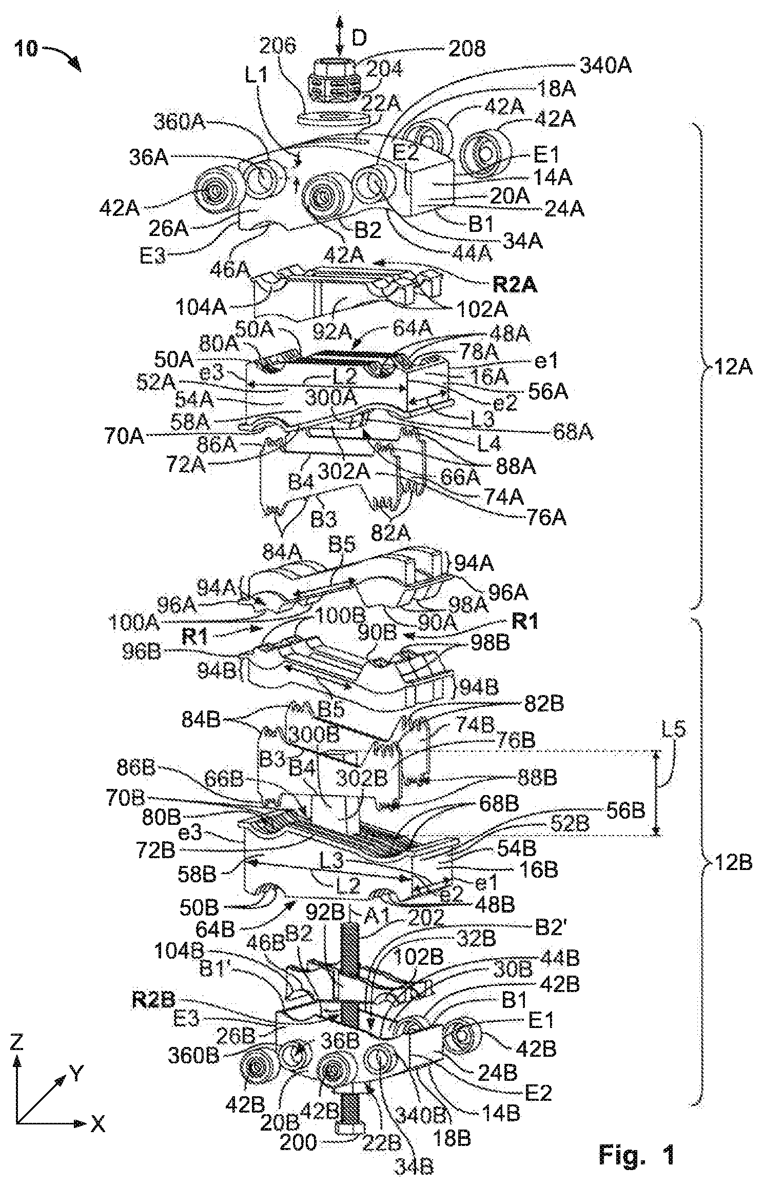
The invention will now be described by way of example with reference to the accompanying Figures, of which: is an exploded perspective view of a cable connector assembly according to an embodiment; is a perspective view of the cable connector assembly in an assembled state without any insulated conductor cables; is a perspective view of the cable connector assembly in the assembled state with a plurality of insulated conductor cables; A is a sectional perspective view of the cable connector assembly of , before a tightening operation; and B is a sectional perspective view of the cable connector assembly of , after a tightening operation.
DETAILED
DESCRIPTION OF THE EMBODIMENT
(S) Features and advantages of the present invention will be described with reference to the drawings. In the description, reference is made to the accompanying figures that are meant to illustrate embodiments of the invention. It is understood that such embodiments do not represent the full scope of the invention. schematically illustrate a cable connector assembly 10 according to an exemplary embodiment the invention. illustrates the cable connector assembly 10 in an exploded view, while illustrates the cable connector assembly 10 in an assembled state. The cable connector assembly 10 is an insulation-piercing connector 10 for electrically connecting cables, in particular for electrically connecting a first insulated cable to a plurality of secondary insulated cables, more in particular for electrically connecting a first insulated cable having a greater diameter than the respective diameter of secondary insulated cables. As illustrated in , the cable connector assembly 10 comprises two sub-assemblies 12 A, 12 B arranged one above the other along a clamping direction D of the cable connector assembly 10 . The clamping direction D is represented by a double arrow “D” parallel to a Z-axis of the Cartesian coordinate system indicated in . In the following, the reference signs comprising the letter “A” refers to the first sub-assembly 12 A corresponding to the upper sub-assembly 12 A illustrated in . The reference signs comprising the letter “B” refers to the second sub-assembly 12 B corresponding to the lower sub-assembly 12 B illustrated in . The first sub-assembly 12 A is substantially symmetrical to the second sub-assembly 12 B by mirror symmetry, also called reflection symmetry, with respect to a plane of symmetry (XY) of the Cartesian coordinate system perpendicular to the clamping direction D, as indicated in . Each sub-assembly 12 A, 12 B comprises a respective main housing 14 A, 14 B and a respective clamping part 16 A, 16 B. In an embodiment, each of the main housings 14 A, 14 B and each of the clamping parts 16 A, 16 B are respectively integrally formed in one-piece in a non-electrically conductive material. For instance, each of the main housings 14 A, 14 B and each of the clamping parts 16 A, 16 B are respectively formed by plastic injection molding. Hence, the cable connector assembly 10 comprises four distinct plastic components 14 A, 14 B, 16 A, 16 B. Each main housing 14 A, 14 B comprises a base 18 A, 18 B from which extends a circumferential wall 20 A, 20 B along the clamping direction D. Each base 18 A, 18 B is provided with a through-hole 22 A, 22 B. In the exemplary embodiments of , the through-holes 22 A, 22 B are oblong. Moreover, in the exemplary embodiments of , the bases 18 A, 18 B are convex surfaces. As further explained below, the combination of the oblong shape of the through holes 22 A, 22 B and the convex surfaces of the bases 18 A, 18 B makes it easier to pivot the sub-assemblies 12 A, 12 B relative to a respective pivot axis parallel to the Y-axis of the Cartesian coordinate system indicated in . Accordingly, the respective pivot axis of the sub-assemblies 12 A, 12 B is perpendicular to the clamping direction D. In other embodiments, the through-holes 22 A, 22 B can have a circular shape and/or the bases 18 A, 18 B can be flat surfaces in a plane (XY) of the Cartesian coordinate system indicated in . In the exemplary embodiments of , each base 18 A, 18 B is a four-sided base. Consequently, each circumferential wall 20 A, 20 B is provided with four faces 24 A-B, 26 A-B, 28 A-B, 30 A-B (only faces 24 A-B, 26 A-B, 28 B, 30 B are visible in the view of ). Each face 24 A, 26 A, 28 A, 30 A (respectively each face 24 B, 26 B, 28 B, 30 B) ends with a respective free-border B 1 , B 1 ′, B 2 , B 2 ′. As better shown in the second-assembly 12 B of , the free-borders B 1 , B 1 ′ respectively longitudinally extend along the Y-axis of the Cartesian coordinate system indicated in . Hence, the free-borders B 1 , B 1 ′ are parallel to each other. The free-borders B 2 , B 2 ′ respectively extend perpendicularly from the free-borders B 1 , B 1 ′ along the X-axis of the Cartesian coordinate system indicated in . The free-borders B 2 , B 2 ′ are parallel to each other. In the main housing 14 A (respectively the main housing 14 B), adjacent faces 24 A, 26 A, 28 A, 30 A (respectively adjacent faces 24 B, 26 B, 28 B, 30 B) are joined to one another by edges E 1 , E 2 , E 3 , E 4 (E 4 is not visible in the view of ). The edge E 1 joins the faces 24 A and 30 A (respectively 24 B and 30 B). The edge E 2 joins the faces 24 A and 26 A (respectively 24 B and 26 B). The edge E 3 joins the faces 26 A and 28 A (respectively 26 B and 28 B). The edge E 4 (not visible in the view of ) joins the faces 28 A and 30 A (respectively 28 B and 30 B). In one embodiment of the present invention, the edges E 1 , E 2 , E 3 , E 4 can have the same length. In the exemplary embodiment shown in , two edges E 1 , E 2 are shorter than the two other edges E 3 , E 4 . The edge E 1 has the same length than the edge E 2 . The edge E 3 has the same length as the edge E 4 . Hence, two opposites faces 28 A and 30 A (respectively 28 B and 30 B) of the circumferential wall 20 A (respectively 20 B) are each respectively provided with edges of different lengths. Consequently, because of the length difference of the edges, the free borders B 2 , B 2 ′ are oblique edges, in particular with respect to the plan (XY). The oblique geometry of the free borders B 2 , B 2 ′ is defined by the entire free border B 2 not being perpendicular to the edges E 2 , E 3 and the entire free border B 2 ′ not being perpendicular to the edges E 1 , E 4 . It is noted that in the exemplary embodiment shown in , the free border B 1 is perpendicular to the edges E 1 , E 4 and the free border B 1 ′ is perpendicular to the edges E 2 , E 3 . Each circumferential wall 20 A, 20 B, respectively consisting of the four faces 24 A-B, 26 A-B, 28 A-B, 30 A-B as mentioned above, defines a housing cavity 32 A, 32 B (only the housing cavity 32 B is visible in the view of ). The respective surface of the faces 24 A-B, 26 A-B, 28 A-B, 30 A-B oriented towards the housing cavity 32 A, 32 B, i.e. to an inside of the sub-assembly 16 A, 16 B, is mentioned hereafter as “internal surfaces”. As further described thereafter, each housing cavity 32 A, 32 B is configured for receiving in translation the clamping part 16 A, 16 B and up to four cables (the cables are not represented in ). In order to be able to insert cables into the housing cavity 32 A, 32 B, the circumferential wall 20 A, 20 B is provided with at least one through-hole sized to the dimensions of a cable. For sake of clarity in the description of the figures, reference is made in the following to the sub-assembly 12 A only. It is noted that the description sub-assembly 12 A, by the mirror symmetry, also applies to the sub-assembly 12 B, wherein the letter “A” following the reference signs is to be replaced by the letter “B”. In the exemplary embodiment shown in , two opposite faces 26 A, 30 A are respectively provided with two circular through-holes each. The face 26 A comprises two circular through-holes 34 A, 36 A. A central axis of each through-hole 34 A, 36 A is parallel to the Y-axis of the Cartesian coordinate system indicated in . Said central axis of the through-holes 34 A, 36 A are respectively aligned with central axis of two further circular through-holes 38 A, 40 A (not visible in the view of ) provided on the opposite face 30 A of the face 26 A. Hence, a cable can be inserted via the through-hole 34 A and lead out by the opposite through hole 40 A. Respectively, a cable can be inserted via the through-hole 36 A and lead out by the opposite through hole 38 A. In a variant wherein four cables are placed in the housing cavity 32 A, as later explained in reference to , each of the four cables can be respectively inserted in a through-hole 34 A, 36 A, 38 A, 40 A and does not exit from the housing cavity 32 A. In the exemplary embodiment shown in , each through-hole 34 A, 36 A, 38 A, 40 A is provided by a respective circular rim 340 A, 360 A, 380 A, 400 A (only the circular rims 340 A, 360 A are visible in ) perpendicularly extending along a length L 1 from the faces 26 A, 30 A of the circumferential wall 20 A. The circular rims 340 A, 360 A, 380 A, 400 A provide a mechanical support to a cable inserted into a respective through-hole 34 A, 36 A, 38 A, 40 A. The circular rims 340 A, 360 A, 380 A, 400 A also serve for mounting a sealing device 42 A on the respective through-hole 34 A, 36 A, 38 A, 40 A so as to seal an interface between the housing cavity 32 A and a cable inserted into one of the through holes 34 A, 36 A, 38 A, 40 A. In the exemplary embodiment shown in , each sealing device 42 A is made of an elastomer material and has an essentially cylindrical shape of a length substantially equal to the length L 1 . In a non-watertight variant of the cable connector assembly 10 , the main housing 14 A is not provided with sealing device 42 A. Hence, in the non-watertight variant, the circular rims 340 A, 360 A, 380 A, 400 A can be optional. As further shown in , the free-border B 2 of the face 26 A (respectively the free-border B 2 ′ of the face 30 A) is provided with two concave recesses 44 A, 46 A. The recesses 44 A, 46 A respectively have a depth extending along the Z-axis. In the following, the clamping part 16 A is further described with respect to . As mentioned above, for sake of clarity in the description of the figures, reference is made to the sub-assembly 12 A only. It is noted that the description of the sub-assembly 12 A also applies to the sub-assembly 12 B, wherein the letter “A” following the reference signs is to be replaced by the letter “B”. The clamping part 16 A comprises a housing 52 A delimited by a circumferential wall 54 A. In order to be insertable in the housing cavity 32 A of the main housing 14 A, the housing 52 A of the clamping part 16 A has a complementary shape of the housing cavity 32 A of the main housing 14 A. As a result, like the circumferential wall 20 A, the circumferential wall 54 A of the clamping part 16 A is provided with four faces 56 A, 58 A, 60 A, 62 A (only the faces 56 A, 58 A are visible in ) extending along the clamping direction D. A length L 2 (as indicated by a double arrow L 2 in ) of the opposite faces 58 A, 60 A is parallel to the X-axis of the Cartesian coordinate system indicated in . A length L 3 (as indicated by a double arrow L 3 in ) of the opposite faces 56 A, 62 A is parallel to the Y-axis of the Cartesian coordinate system indicated in . The lengths L 2 and L 3 as defined above are respectively adapted to the internal dimensions (not visible in ) of the housing cavity 32 A. In particular, the lengths L 2 and L 3 are determined such that the faces 56 A, 58 A, 60 A, 62 A of the clamping part 16 A respectively slide along the faces 24 A, 26 A, 28 A, 30 A of the housing cavity 32 A of the main housing 14 A along the clamping direction D. The selection of the lengths L 2 and L 3 is made so as to avoid an excess of friction between the faces 56 A, 58 A, 60 A, 62 A of the clamping part 16 A and the faces 24 A, 26 A, 28 A, 30 A of the housing cavity 32 A of the main housing 14 A for allowing a translation motion between the main housing 14 A for and the clamping part 16 A without too much resistance for an installer. It is understood that the faces of the main housing 14 A along which the faces of the clamping part 16 A translate, correspond to the internal surfaces of the faces 24 A, 26 A, 28 A, 30 A of the housing cavity 32 of the main housing 14 A. Accordingly, the faces of the clamping part 16 A translating on and along said internal surfaces of the housing cavity 32 A of the main housing 14 A correspond to external surfaces of the faces 56 A, 58 A, 60 A, 62 A of the clamping part 16 A. The translation of the said internal surfaces 24 A, 26 A, 28 A, 30 A on said external surfaces 56 A, 58 A, 60 A, 62 A is better shown by the cut-view of A and 4 B , in particular by the encircled zone T 1 . In another embodiment, to further facilitate the translation of the clamping part 16 A with respect to the main housing 14 A, the internal surfaces 24 A, 26 A, 28 A, 30 A of the housing cavity 32 of the main housing 14 A and the external surfaces 56 A, 58 A, 60 A, 62 A of the clamping part 16 A can be respectively provided with guiding elements, like longitudinal grooves extending along the clamping direction D. The clamping part 16 A is designed so that a first side 64 A of the housing 52 A, being perpendicular to the faces 56 A, 58 A, 60 A, 62 A, is configured for receiving at least one cable. In the exemplary embodiment shown in , the first side 64 A of the housing 52 A is provided with the two concave recesses 48 A, 50 A extending along the Y-axis of the Cartesian coordinate system indicated in . The recesses 48 A, 50 A respectively have a depth extending along the Z-axis. The two recesses 48 A, 50 A are adapted to the dimension of cables to be clamped between the first side 64 A of the housing 52 A and an internal surface 19 A of the base 18 A of the main housing 14 A, as better shown in the cut-views of A and 4 B . The clamping part 16 A is provided with a second side 66 A, substantially opposite to the first side 64 A along the clamping direction D. As the clamping part 16 A has a complementary shape to the main housing 14 A, in the exemplary embodiment shown in , the housing 52 A is also provided with edges e 1 , e 2 , e 3 , e 4 (e 4 is not visible in ) of different lengths, which are respectively proportional to the edges E 1 , E 2 , E 3 , E 4 of the main housing 14 A. The edge e 1 joins the faces 56 A and 62 A. The edge e 2 joins the faces 56 A and 58 A. The edge e 3 joins the faces 58 A and 60 A. The edge e 4 (not visible in the view of ) joins the faces 60 A and 62 A. Consequently, because of the length difference of the edges e 1 to e 4 , the second side 66 A is on oblique surface. In other words, the entire second side 66 A is not parallel to the first side 64 A extending in the plan (XY). The second side 66 A is provided with two concave recesses 68 A, 70 A. Each concave recesses 68 A, 70 A has a complementary shape to a cable. The recesses 68 A, 70 A respectively have a depth extending along the Z-axis. In the exemplary embodiment shown in , the second side 66 A is provided with a circumferential shoulder 72 A. The circumferential shoulder 72 A contributes to ease the manufacturing process of the clamping part 16 A by plastic injection molding. The circumferential shoulder 72 A can also provide a stop when said circumferential shoulder 72 A abuts against the free borders B 1 , B 1 ′, B 2 , B 2 ′ of the main housing 14 A. In a variant, the second side 66 A is not provided with a circumferential shoulder. The clamping part 16 A is further configured to accommodate insulation piercing devices 74 A, 76 A. In the exemplary embodiment shown in , said insulation piercing devices 74 A, 76 A are substantially flat and are supported in the housing 52 A by an interference fit between each insulation piercing device 74 A, 76 A and a respective receptacle 78 A, 80 A provided in the housing 52 A. Said receptacle 78 A, 80 A extend inside the housing 52 A from the first side 64 A to the second side 66 A in parallels plans to the plan (XZ). The insulation piercing devices 74 A, 76 A are inserted and hold in the respective receptacles 78 A, 80 A. In a variant, the insulation piercing devices 74 A, 76 A are supported in the housing 52 A by a different connection than by interference fit. For instance, the housing 52 A, made of rigid plastic, can be overmolded on the insulation piercing devices 74 A, 76 A. The insulation piercing device 74 A and the insulation piercing device 76 A are arranged in the housing 52 A so as to be respectively positioned in plans parallels to each other, both parallel to the plan (XZ). The insulation piercing device 74 A is identical to the insulation piercing device 76 A. Hence, for sake of clarity, the description of the insulation piercing device herebelow is only made in reference to insulation piercing device 74 A and the same description applies to the insulation piercing device 76 A. It is noted that the insulation piercing device 74 A (respectively 76 A) is symmetrical to the insulation piercing device 74 B (respectively 76 B) by a mirror symmetry with respect to a plan (XY). Hence, the same description also applies to the insulation piercing device 74 A, 76 B. As the insulation piercing devices 74 A, 74 B, 76 A, 76 B can be all identical, a standardized manufacturing is possible for low cost. However, the insulation piercing device 74 A, 74 B, 76 A, 76 B do not need to be identical. Thus, in further variants, the size and the shape of one more of insulation piercing device could vary depending on the installation requirements. As shown in , the insulation piercing device 74 A is integrally formed in one-piece in a metal or metal alloy material, in particular in copper or tinned-plated copper, i.e. in an electrically conductive material. In the exemplary embodiment shown in , the insulation piercing device 74 A comprises four serrated blades 82 A, 84 A, 86 A, 88 A. The function of the insulation piercing device 74 A, 74 B, 76 A, 76 B is to establish an electrical contact between the cables. In the exemplary embodiment shown in , the extremities of the serrated blades 82 A, 84 A, 86 A, 88 A are provided with tooth extending in a direction parallel to the clamping direction D. The serrated blades 82 A, 84 A, 86 A, 88 A of the insulation piercing device 74 A are configured for piercing respective insulation layers and contacting respective conductors of cables. In a variant, at least one of the blades 82 A, 84 A, 86 A, 88 A has a V-shape instead of a tooth shape. The V-shape must be sharped enough to pierce an insulation layer of a cable. In another variant, the design of the serrated blades 82 A, 84 A, 86 A, 88 A is configured for piercing a bare cable. In the plan (XZ), the geometry of the insulation piercing device 74 A is complementary to the geometry of the faces 58 A, 62 A of the clamping part 16 A, said faces 58 A, 62 A having a complementary shape to the faces 26 A, 30 A of the main housing 14 A. As a result, a free-border B 3 joining the serrated blades 82 A and 84 A is non-parallel to a free-border B 4 joining the serrated blades 86 A and 88 A. In other words, the free-border B 3 extends along an oblique direction with respect to the free-border B 4 . The border B 4 extends along a direction parallel to the X-axis. In reference to the overall cable connector assembly 10 and in view of the above, a first clamping region R 1 is formed between the two sub-assemblies 12 A, 12 B. In the first clamping region R 1 , at least one cable can be received between the recesses 68 A and 68 B and clamped by the serrated blades 82 A and 82 B. In a variant, two cables (instead of one) can be inserted between the recesses 68 A and 68 B. One cable can be pierced by the serrated blades 82 A of the insulation piercing device 74 A and the serrated blades 82 B of the insulation piercing device 74 B. Another cable can be pierced by the serrated blades 82 A of the insulation piercing device 76 A and the serrated blades 82 B of the insulation piercing device 76 B. A further cable can be received in the first clamping region R 1 between the recesses 70 A and 70 B, and clamped by the serrated blades 84 A and 84 B. In a variant, two cables (instead of one) can be inserted between the recesses 70 A and 70 B. One cable can be pierced by the serrated blades 84 A of the insulation piercing device 74 A and the serrated blades 84 B of the insulation piercing device 74 B. Another cable can be pierced by the serrated blades 84 A of the insulation piercing device 76 A and the serrated blades 84 B of the insulation piercing device 76 B. Hence, up to four cables can be clamped and pierced in the first clamping region R 1 . As shown in , the face 66 A of the clamping part 16 A facing the face 66 B of the other clamping part 16 B in the first clamping region R 1 extend within a plan that is non-parallel to the plan in which extends the face 66 B of the clamping part 16 B. The asymmetrical design according to the embodiment illustrated in of the insulation piercing device 74 A-B, 76 A-B, the clamping parts 16 A-B and the main housing 14 A-B allows to adapt more easily a difference of diameter between a cable inserted between the recesses 68 A and 68 B and another cable inserted between the recesses 70 A and 70 B. In the exemplary embodiment shown in , the recesses 68 A and 68 B are configured for receiving a cable having a greater diameter than a cable insertable between the recesses 70 A and 70 B. Moreover, two secondary clamping regions R 2 A and R 2 B are respectively formed in the housing cavities 32 A, 32 B between the clamping part 16 A, 16 B and the main housing 14 A, 14 B. In the secondary clamping region R 2 A, at least one cable can be received inside the housing cavity 32 A between an internal surface (not visible in , but see reference 19 A in A and 4 B ) of the base 18 A of the main housing 14 A and the recess 48 A of the first side 64 A of the clamping part 16 A. Said cable can be pierced by the serrated blades 88 A. It is noted that in a variant, like in the embodiment illustrated in , two cables (instead of one) can be inserted between said internal surface 19 A (not visible in ) of the base 18 A of the main housing 14 A and the recess 48 A of the first side 64 A of the clamping part 16 A. One cable can be pierced by the serrated blades 88 A of the insulation piercing device 74 A and another cable can be pierced by the serrated blades 88 A of the insulation piercing device 76 A. A further cable can be received in the secondary clamping regions R 2 A between said internal surface 19 A (not visible in ) of the base 18 A of the main housing 14 A and the recess 50 A of the first side 64 A of the clamping part 16 A. Said further cable can be clamped by the serrated blades 86 A. It is noted that in a variant, like in the embodiment illustrated in , two cables instead of one) can be inserted between said internal surface 19 A (not visible in ) of the base 18 A of the main housing 14 A and the recess 50 A of the first side 64 A of the clamping part 16 A. One cable can be pierced by the serrated blades 86 A of the insulation piercing device 74 A and another cable can be pierced by the serrated blades 86 A of the insulation piercing device 76 A. Hence, up to four cables can be pierced in the secondary clamping region R 2 A. In the secondary clamping region R 2 B, one cable can be received inside the housing cavity 32 B between an internal surface (not visible in , but see reference 19 B in A and 4 B ) of the base 18 B of the main housing 14 B and the recess 48 B of the first side 64 B of the clamping part 16 B. Said cable can be clamped by the serrated blades 88 A. It is noted that in a variant, like in the embodiment illustrated in , two cables instead of one) can be inserted between said internal surface 19 B (not visible in ) of the base 18 B of the main housing 14 B and the recess 48 B of the first side 64 B of the clamping part 16 B. One cable can be pierced by the serrated blades 88 B of the insulation piercing device 74 B and another cable can be pierced by the serrated blades 88 B of the insulation piercing device 76 B. A further cable can be received in the secondary clamping regions R 2 B between said internal surface 19 B (not visible in ) of the base 18 B of the main housing 14 B and the recess 50 B of the first side 64 B of the clamping part 16 B. Said further cable can be pierced by the serrated blades 86 B. It is noted that in variant, like in the embodiment illustrated in , two cables instead of one) can be inserted between said internal surface 19 B (not visible in ) of the base 18 B of the main housing 14 B and the recess 50 B of the first side 64 B of the clamping part 16 B. One cable can be pierced by the serrated blades 86 B of the insulation piercing device 74 B and another cable can be pierced by the serrated blades 86 B of the insulation piercing device 76 B. Hence, up to four cables can be pierced in the secondary clamping region R 2 B. The structure of the cable connector assembly 10 according to the present invention is thus configured for piercing up to twelve cables, in particular up to four cable in each clamping region R 1 , R 2 A, R 2 B. In the exemplary embodiment shown in , the cable connector assembly 10 further comprises sealing devices 90 A, 90 B, 92 A, 92 B. Each of the sealing devices 90 A, 90 B, 92 A, 92 B may integrally formed in an elastomer material, like rubber. The sealing devices 90 A, 90 B, 92 A, 92 B can be overmolded on the respective insulation piercing device 74 A-B, 76 A-B and housings 52 A- 52 B. Each sealing device 90 A, 90 B is provided at the second side 66 A, 66 B of the respective clamping part 16 A, 16 B for sealing an interface between the first clamping region R 1 and the respective clamping part 16 A, 16 B. Each sealing device 90 A, 90 B comprises a portion 94 A, 94 B adapted to be tightly inserted in the respective housing 52 A, 52 B of the clamping part 16 A, 16 B. Each sealing device 90 A, 90 B also comprises a shoulder 96 A, 96 B to further improve the sealing properties. Each sealing device 90 A, 90 B comprises protuberances 98 A, 98 B through which extend the serrated blades 82 A, 82 B. Each sealing devices 90 A, 90 B further comprises protuberances 100 A, 100 B through which extend the serrated blades 84 A, 84 B. The protuberances 98 A, 98 B, 100 A, 100 B extended substantially in a perpendicular direction, parallel to the clamping direction D, from the portion 94 A, 94 B. An insertion of the 98 A, 98 B, 100 A, 100 B inside the respective housing 52 A, 52 B of the clamping part 16 A, 16 B is prevented by the dimensions of said protuberances and the shoulders 96 A, 96 B. The border B 5 of the sealing devices 90 A, 90 B joining respectively the protuberance 98 A, 98 B to the protuberance 100 A, 100 B does not extend parallel to the X-axis because of the asymmetrical geometry of the clamping parts 16 A, 16 B in the exemplary embodiment shown in . The sealing device 92 A is provided inside the housing cavity 32 A of the main housing 14 A for sealing the first face 64 A of the clamping part 16 A at an interface with the secondary clamping region R 2 A. Respectively, the sealing device 92 B is provided inside the housing cavity 32 B of the main housing 14 B for sealing the first face 64 B of the clamping part 16 B at an interface with the secondary clamping region R 2 B. Each sealing device 92 A, 92 B is provided with concave recesses 102 A, 102 B, 104 A, 104 B for receiving one or two cables each. The concave recesses 102 A, 102 B allow sealing an interface with the concave recesses 48 A, 48 B of the clamping part 16 A, 16 B. The concave recesses 104 A, 104 B allow sealing an interface with the concave recesses 50 A, 50 B clamping part 16 A, 16 B. The shape and dimensions of the concave recesses 102 A, 102 B, 104 A, 104 B of the sealing devices 92 A, 92 B are thus adapted to the dimensions of the clamping parts 16 A, 16 B and cables to be inserted therein. The serrated blades 86 A extend through the concave recesses 104 A of the sealing device 92 A for piercing a cable at the secondary clamping region R 2 A. Respectively, the serrated blades 86 B extend through the concave recesses 104 B of the sealing devices 92 B for piercing a cable at the secondary clamping region R 2 B. The serrated blades 88 A extend through the concave recesses 102 A of the sealing device 92 A for piercing a cable at the secondary clamping region R 2 A. Respectively, the serrated blades 88 B extend through the concave recesses 102 B of the sealing devices 92 B for piercing a cable at the secondary clamping region R 2 B. In order to keep cables clamped in the clamping regions R 1 , R 2 A, R 2 B, the cable connector assembly 10 comprises tightening device 200 . The tightening device 200 allows tightening the two sub-assemblies 12 A, 12 B. The tightening of the two sub-assemblies 12 A, 12 B is achieved by their mutual translation, the sub-assemblies 12 A, 12 B moving towards each other along the clamping direction D. In the embodiment illustrated in , the tightening device 200 comprise a screw 202 of longitudinal axis A 1 inserted through the two sub-assemblies 12 A, 12 B, where a bolt 204 can be used for the tightening. As shown in , the screw 202 can be inserted essentially along a central vertical axis of the cable connector assembly 10 . Hence, the screw 202 extends along the clamping direction D through the main housing 14 A, the sealing device 92 A, the clamping part 16 A, the sealing device 90 A, the sealing device 90 B, the clamping part 16 B, the sealing device 92 B and the main housing 14 B. As further illustrated in , a spacer 206 can also be used between a head 208 of the screw 202 and the base 18 A of the main housing 14 A. The screw 202 further comprises a bolt 210 positioned so as to abut on the main housing 14 B. The main housings 14 A, 14 B and the clamping parts 16 A, 16 B are all arranged between the head 208 and the bolt 210 along the central axis A 1 of the screw 202 . It is possible that, once the cable connector assembly 10 is assembled, like in , an end part of the screw 202 is deliberately damaged so that the cable connector assembly 10 can no longer be disassembled. Furthermore, it is also possible to use a shear-head bolt, such that the operator will stop tightening the bolt once its shear-head breaks. As further illustrated, in , the cable connector assembly 10 comprises anti-rotation devices 300 A, 300 B for preventing a rotation of each clamping part 16 A, 16 B with respect to a rotation axis aligned with the longitudinal axis A 1 of the screw 202 and parallel to the clamping direction D. The anti-rotation device 300 A of the clamping part 16 A is formed by a non-circular duct 302 A, in particular a square duct 302 A, for receiving the screw 202 therein. The non-circular duct 302 A extends along the clamping direction D from the first face 64 A towards the second face 66 A and protrudes beyond to the second face 66 A along a length L 4 , as shown in . The anti-rotation device 300 B of the clamping part 16 B is also formed by a non-circular duct 302 B, in particular a square duct 302 B, for receiving the screw 202 therein. The non-circular duct 302 B extends along the clamping direction D from the first face 64 B towards the second face 66 B and protrudes beyond to the second face 66 B along a length L 5 , as shown in . The internal circumference of the non-circular duct 302 B is dimensioned according to the diameter of the screw 202 for receiving the screw 202 . The respective internal circumferences (not visible) of the non-circular ducts 302 A, 302 B are dimensioned in a complementary manner so that the non-circular ducts 302 B of length L 5 can be received and translate within the non-circular ducts 302 B of length L 4 along the clamping direction D. The length L 5 is greater than the length L 4 . The respective non-circular cross-section of the ducts 302 A, 302 B in a plan perpendicular to the longitudinal axis A 1 of the screw 202 allows preventing a rotation of the clamping parts 16 A, 16 B in a plan (XY) with respect to a rotation axis aligned with the longitudinal axis A 1 of the screw 202 by interference-fit, also known as friction-fit. Furthermore, the main housing 14 B is provided at the base 18 B with a recess for receiving the bolt 210 , such that a form-fit connection of said bolt 210 in the recess of the main housing 14 B prevents a rotation of said main housing 14 B with respect to the central axis A 1 of the screw 200 . The anti-rotation devices 300 A, 300 B provide the advantage that the installer is able to tighten the tightening device 200 , for instance a screw and a bolt, without worrying about manually keeping the sub-assemblies 12 A, 12 B from rotation relatively to a central axis of the screw 202 . It thus allows improving the ease of installation of the cable connector assembly 10 . illustrates the cable connector assembly 10 of in an assembled state and without any insulated conductor cables, i.e. before the tightening operations have taken place. In the assembled state, as shown in , each clamping part 16 A, 16 B is partially inserted into the respective main housing 14 A, 14 B. Each clamping part 16 A, 16 B protrudes beyond the free borders B 1 , B 1 ′, B 2 , B 2 ′ (only B 1 and B 2 are visible in the ) of the main housing 14 A, 14 B along a distance d 0 in the assembled state and before the tightening operations. The distance d 0 is smaller than the length of any of the edges e 1 , e 2 , e 3 , e 4 , as each clamping part 16 A, 16 B is partially inserted into the respective main housing 14 A, 14 B. The installation process of the cable connector assembly 10 is described thereafter with reference to to 4 B . Elements with the same reference numeral already described and illustrated in will not be described in detail again but reference is made to their description above. At the step shown in , a main cable C 1 , for instance a trunk cable C 1 , of diameter c 1 is installed in the first clamping region R 1 between the recesses 68 A, 68 B. In a variant, two main cables, like two trunk cables, can be installed between the recesses 68 A, 68 B in the first clamping region R 1 along parallel directions to one another. A tap cable C 2 of diameter c 2 , wherein c 2 is less than c 1 , is installed in the first clamping region R 1 between the recesses 70 A, 70 B. In a variant, two tap cables can be installed between the recesses 70 A, 70 B in the first clamping region R 1 along parallel directions to one another. In another embodiment, wherein only a trunk cable and no tap cable is required in the first clamping region R 1 , a dummy cable can be inserted between the recesses 70 A, 70 B so as to provide a sufficiently good force (i.e. strain) transmission in the cable connector assembly 10 . As a variant, instead of using a dummy cable, the opposite blades 84 A, 84 B can have a complementary geometry providing a form-fit connection directly between said opposite blades 84 A, 84 B. As a result, there is no need to insert a dummy cable between the opposite blades 84 A, 84 B, and the diameter of the “missing” tap cable can be compensated by the dimensions of the blades 84 A, 84 B forming a form-fit connection. A tap cable C 3 of diameter c, wherein c is less than c 1 , is inserted along an insertion direction D 2 in the cavity housing 32 A via the through-hole 34 A. It is noted that the diameter c can be different from the diameter c 2 . The diameters c, c 1 and c 2 take in account any insulation layer of the cables. A tap cable C 4 of diameter c is inserted along the insertion direction D 2 in the cavity housing 32 A via the through-hole 36 A. A tap cable C 5 of diameter c is inserted along an insertion direction −D 2 , parallel but opposite to the insertion direction D 2 , in the cavity housing 32 A via the through-hole 38 A. A tap cable C 6 of diameter c is inserted along the insertion direction −D 2 in the cavity housing 32 A via the through-hole 40 A. A tap cable C 7 of diameter c is inserted along the insertion direction D 2 in the cavity housing 32 B of the main housing 14 B via the through-hole 34 B. A tap cable C 8 of diameter c is inserted along the insertion direction D 2 in the cavity housing 32 B via the through-hole 36 B. A tap cable C 9 of diameter c is inserted along the insertion direction −D 2 in the cavity housing 32 B via the through-hole 38 B. A tap cable C 10 of diameter c is inserted along the insertion direction −D 2 in the cavity housing 32 B via the through-hole 40 B. The parallel insertion directions D 2 , −D 2 are perpendicular to the clamping direction D. In the cable connector assembly 10 , the main cable C 1 and tap cable C 2 extend longitudinally along an insertion directions D 2 , −D 2 . In a variant, one or more of the tap cables C 3 to C 10 has/have a diameter different than the diameter c. A shows a step following the step shown in . At the step of A , the cables C 1 to C 10 have been inserted into the cable connector assembly 10 . As shown in A , the main cable C 1 (e.g. the trunk cable C 1 ) is placed in the first clamping region R 1 between the serrated blades 82 A, 82 B. At the step of A , before the tightening step (shown in B ), the serrated blades 82 A, 82 B are distanced from each other along the clamping direction D by a gap g. The tap cable C 2 is placed in the first clamping region R 1 between the serrated blades 84 A, 84 B. At the step of A , before the tightening step (shown in B ), the serrated blades 84 A, 84 B are distanced from each other along the clamping direction D by a gap g 2 , wherein g 2 is less than g 1 , as the cable C 2 has a smaller diameter c 2 than the diameter c 1 of the main cable C 1 . The tap cable C 3 is placed in the secondary clamping region R 2 A between the serrated blades 86 A of the insulation piercing device 74 A and an internal surface 19 A of the base 18 A. The internal surface 19 A is oriented towards the inside of the housing cavity 32 A as shown in A . The internal surface 19 A of the base 18 A corresponds to a bottom of the housing cavity 32 A. The tap cable C 4 is placed in the secondary clamping region R 2 A between the serrated blades 88 A of the insulation piercing device 74 A and the internal surface 19 A of the base 18 A. The tap cable C 5 is placed in the secondary clamping region R 2 A between the serrated blades 86 A of the insulation piercing device 76 A and the internal surface 19 A of the base 18 A. The tap cable C 6 is placed in the secondary clamping region R 2 A between the serrated blades 88 A of the insulation piercing device 76 A and the internal surface 19 A of the base 18 A. At the step of A , before the tightening step (shown in B ), the serrated blades 86 A, 88 A are distanced from the internal surface 19 A of the base 18 A along the clamping direction D by a gap g 3 . Respectively, the tap cable C 7 is placed in the secondary clamping region R 2 B between the serrated blades 86 B of the insulation piercing device 74 B and an internal surface 19 B of the base 18 B. The internal surface 19 B is oriented towards the inside of the housing cavity 32 B as shown in A . The internal surface 19 B of the base 18 B corresponds to a bottom of the housing cavity 32 B. The tap cable C 8 is placed in the secondary clamping region R 2 B between the serrated blades 88 B of the insulation piercing device 74 B and the internal surface 19 B of the base 18 B. The tap cable C 9 is placed in the secondary clamping region R 2 B between the serrated blades 86 B of the insulation piercing device 76 B and the internal surface 19 B of the base 18 B. The tap cable C 10 is placed in the secondary clamping region R 2 B between the serrated blades 88 B of the insulation piercing device 76 B and the internal surface 19 B of the base 18 B. At the step of A , before the tightening step (shown in B ), the serrated blades 86 B, 88 B are distanced from the internal surface 19 B of the base 18 B along the clamping direction D by a gap g 4 . As can be seen from the embodiment represented by the cut-views of A and 4 B , the internal surface 19 B is provided with grooves for receiving the cables C 3 to C 10 . In a variant (not represented), a wedge can be provided between said groove and one of the cables C 3 to C 10 to better cope with a difference in cable diameter in the cable connector assembly 10 . Once all cables C 1 to C 10 have been inserted into the cable connector assembly 10 , the tightening device is tightened by an operator. A rotation of the head 208 and the bolt 210 relative to the screw 202 causes a mutual translation movement of the sub-assemblies 12 A, 12 B towards each other along the clamping direction D. Moreover, each of the two sub-assemblies 12 A, 12 B is pivotable relative to the longitudinal axis A 1 of the screw 202 . The pivot motion is facilitated by the combination of the oblong shape of the through holes 22 A, 22 B and the convex surfaces of the bases 18 A, 18 B. As a result of the tightening operation, the cable connector assembly 10 is in an assembled and connected state. In the assembled and connected state, an electrical contact is established between the main cable C 1 and the tap cables C 2 to C 10 . The assembled and connected state is represented by the B . During the tightening operation, at the upper part of the cable connector assembly 10 shown in B , the head 208 , in particular the shear head 208 , generates a force F on the main housing 14 A. The main housing 14 A, in particular the internal surface 19 B, compresses the tap cables C 3 , C 4 , C 5 , C 6 on the serrated blades 86 A, 88 A in the secondary clamping region R 2 A with a force F/ 4 . This force F/ 4 pushes the serrated blades 82 A, 84 A into the main cable C 1 and the tap cable C 2 . As a result, after tightening, the serrated blades 86 A, 88 A are distanced from the internal surface 19 A of the base 18 A along the clamping direction D by a gap G 3 , wherein G 3 is less than g 3 . At the bottom part of the cable connector assembly 10 , the bolt 210 returns the force −F to the main housing 14 B, in particular the internal surface 19 B, which compresses the tap cables C 7 , C 8 , C 9 , C 10 on the serrated blades 86 B, 88 B in the secondary clamping region R 2 B with a force −F/ 4 . This force −F/ 4 pushes the serrated blades 82 B, 84 B into the main cable C 1 and the tap cable C 2 . The forces F, —F, F/ 4 and −F/ 4 are parallel to the clamping direction D. After the tightening operation, the serrated blades 86 B, 88 B are distanced from the internal surface 19 B of the base 18 B along the clamping direction D by a gap G 4 , wherein G 4 is less than g 4 . At the first clamping region R 1 , the serrated blades 82 A, 82 B are distanced from each other along the clamping direction D by a gap G 1 , wherein G 1 is less than 1 . Respectively, the serrated blades 84 A, 84 B are distanced from each other along the clamping direction D by a gap G 2 , wherein G 2 is less than g 2 . Hence, in the assembled and connected state is represented by the B , the tightening of the cable connector assembly 10 along the clamping direction D has the effect of reducing the initial gaps g 1 , g 2 , g 3 , g 4 between the serrated blades at the region R 1 and between the serrated blades and the main housing 14 at the regions R 2 A, R 2 B to respective smaller distance G 1 , G 2 , G 3 , G 4 . It leads to the perforation of the insulating layer of the cables C 1 -C 10 by the serrated blades B 2 , 84 , 86 , 88 which allows causing a contact between the teeth of the serrated blades 82 , 84 , 86 , 88 with the conductor core of the cables C 1 -C 10 . Hence, an electrical contact between the cables C 1 -C 10 , i.e. their conductor cores, and the serrated blades 82 , 84 , 86 , 88 can be established in the assembled and connected state of B by the translation of the sub-assemblies 12 A, 12 B towards each other along the clamping direction D. As shown in B , in the assembled and connected state, each clamping part 16 A, 16 B protrudes beyond the free borders B 1 , B 1 ′, B 2 , B 2 ′ (only B 1 is visible in the A ) of the main housing 14 A, 14 B along a distance d 1 , wherein d 1 is less than d 0 . To better deal with cables of different diameters, the first clamping region R 1 can be rendered asymmetric for receiving two cables of different diameters, in particular by providing an oblique face to the clamping parts 16 A, 16 B. The B highlights that the non-parallel borders B 3 , B 4 allows better dealing with the differences of diameters between the main cable C 1 and the tap cable C 2 . The cable connector assembly 10 is configured to clamp up to twelve cables and to cope with cables of different diameters by the two translatable and pivotable sub-assemblies 12 A, 12 B, and translatable clamping parts 16 A, 16 B into their respective main housings 14 A, 14 B. The present invention is, however, not limited to the above-mentioned asymmetric embodiment. Hence, in a variant, the borders B 3 , B 4 can respectively extend between the blades 82 , 84 and the blades 86 , 88 along parallel directions to each other. The clamping parts 16 A, 16 B are used for the clamping taking place in all clamping regions R 1 , R 2 A, R 2 B. The sealing devices 42 A, 42 B, 90 A, 90 B, 92 A, 92 B allow providing a cable connector assembly 10 adapted for watertight application. The present invention is however not limited to the above-mentioned watertight embodiment. The cable connector assembly 10 for electrically connecting cables allowing the connection of one main trunk cable C 1 to a plurality of tap cables C 2 -C 10 having a respective different diameter than the main trunk cable, in particular by one cable connector assembly wherein only one tightening device 200 needs to be operated for the installation. All previously discussed embodiments are not intended as limitations but serve as examples illustrating features and advantages of the invention. It is to be understood that some or all of the above described features can also be combined in different ways.
Figures (4)
Citations
This patent cites (10)
- US8678852
- US11177585
- US2019/0140368
- US1139496
- US2541684
- US2882040
- US2871720
- US3836304
- US2930847
- US3017494