Display Device, Display System, and Display Driving Method
Abstract
A display device according to the present disclosure includes: a reception circuit that is configured to receive a piece of first image data and a piece of second image data, the piece of first image data representing an entire image having a first resolution, the piece of second image data representing a first partial image having a second resolution higher than the first resolution, and the first partial image corresponding to a portion of the entire image; a display section including a plurality of pixels; and a display drive circuit that is configured to perform first driving and second driving, the first driving in which the plurality of pixels is driven in units of a first number of pixels on the basis of the piece of first image data, the second driving in which two or more pixels provided in a region corresponding to the first partial image of the plurality of pixels are driven in units of a second number of pixels on the basis of the piece of second image data, and the second number being smaller than the first number.
Claims (20)
1 . A display device comprising: a reception circuit that is configured to receive a piece of first image data and a piece of second image data, the piece of first image data representing an entire image having a first resolution, the piece of second image data representing a first partial image having a second resolution higher than the first resolution, and the first partial image corresponding to a portion of the entire image; a display section including a plurality of pixels; a display drive circuit that is configured to perform first driving and second driving, the first driving in which the plurality of pixels is driven in units of a first number of pixels on a basis of the piece of first image data, the second driving in which two or more pixels provided in a region corresponding to the first partial image of the plurality of pixels are driven in units of a second number of pixels on a basis of the piece of second image data, and the second number being smaller than the first number; and a decompression circuit that is configured to decompress a piece of compressed image data of the piece of first image data and the piece of second image data, wherein at least one of the piece of first image data or the piece of second image data is compressed.
11 . A display device comprising: a reception circuit that is configured to receive a piece of first image data and a piece of second image data, the piece of first image data representing an entire image having a first resolution, the piece of second image data representing a first partial image having a second resolution higher than the first resolution, and the first partial image corresponding to a portion of the entire image; a display section including a plurality of pixels; a display drive circuit that is configured to perform first driving and second driving, the first driving in which the plurality of pixels is driven in units of a first number of pixels on a basis of the piece of first image data, the second driving in which two or more pixels provided in a region corresponding to the first partial image of the plurality of pixels are driven in units of a second number of pixels on a basis of the piece of second image data, and the second number being smaller than the first number; and a decompression circuit that is configured to decompress a piece of compressed image data of the piece of first image data and the piece of second image data, wherein both the piece of first image data and the piece of second image data are compressed, and a compression ratio of the piece of first image data and a compression ratio of the piece of second image data are different from each other.
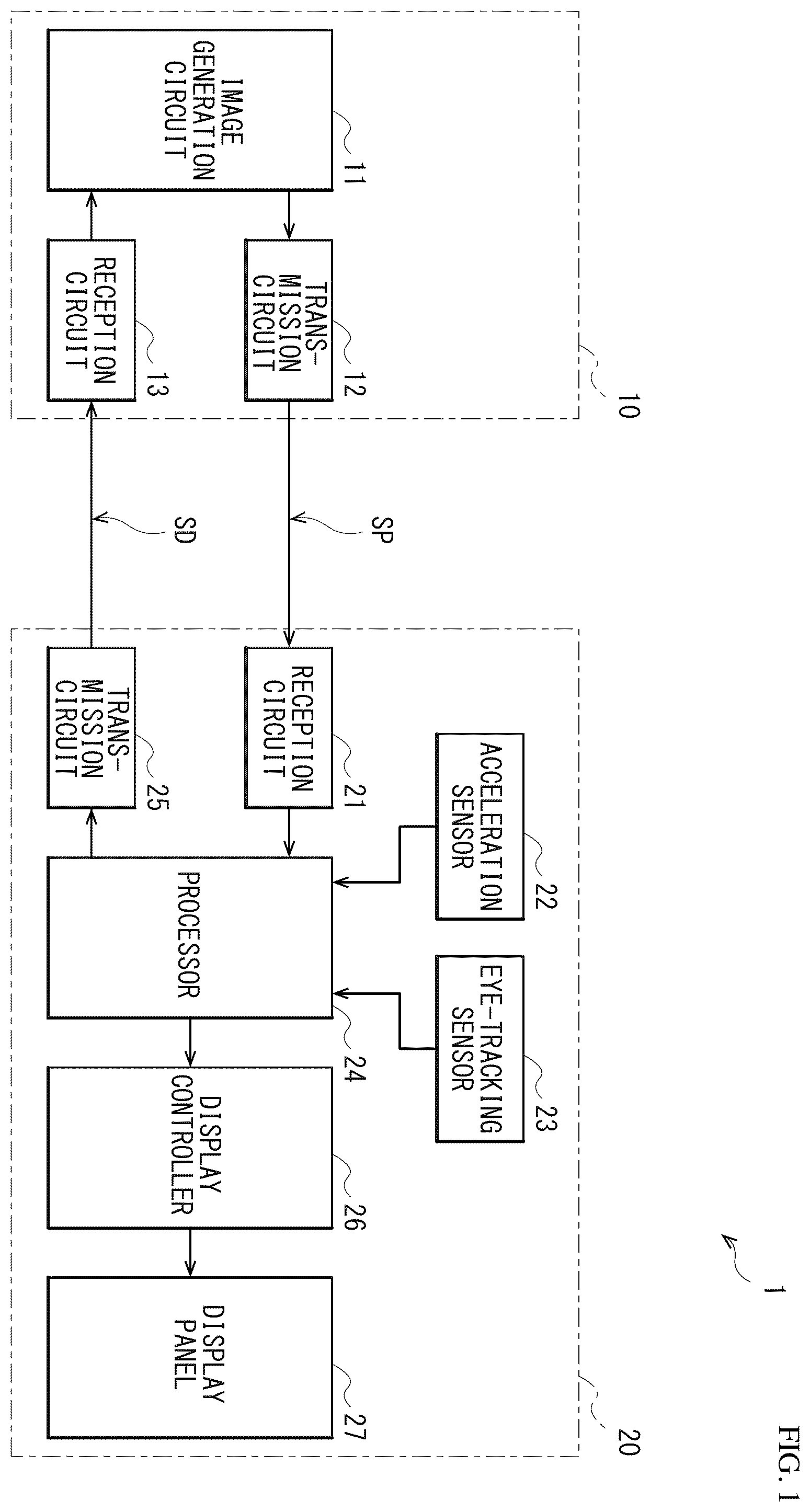
16 . A display system comprising: an image generation device that is configured to transmit a piece of first image data and a piece of second image data, the piece of first image data representing an entire image having a first resolution, the piece of second image data representing a first partial image having a second resolution higher than the first resolution, and the first partial image corresponding to a portion of the entire image; and a display device, the display device including a reception circuit that is configured to receive the piece of first image data and the piece of second image data, a display section including a plurality of pixels, a display drive circuit that is configured to perform first driving and second driving, the first driving in which the plurality of pixels is driven in units of a first number of pixels on a basis of the piece of first image data, the second driving in which two or more pixels provided in a region corresponding to the first partial image of the plurality of pixels are driven in units of a second number of pixels on a basis of the piece of second image data, the second number being smaller than the first number, and a decompression circuit that is configured to decompress a piece of compressed image data of the piece of first image data and the piece of second image data, wherein at least one of the piece of first image data or the piece of second image data is compressed.
20 . A display driving method comprising: transmitting a piece of first image data and a piece of second image data, the piece of first image data representing an entire image having a first resolution, the piece of second image data representing a first partial image having a second resolution higher than the first resolution, the first partial image corresponding to a portion of the entire image; receiving the piece of first image data and the piece of second image data; performing first driving in which a plurality of pixels is driven in units of a first number of pixels on a basis of the piece of first image data; and performing second driving in which two or more pixels provided in a region corresponding to the first partial image of the plurality of pixels are driven in units of a second number of pixels on a basis of the piece of second image data, the second number being smaller than the first number; and decompressing a piece of compressed image data of the piece of first image data and the piece of second image data, wherein at least one of the piece of first image data or the piece of second image data is compressed.
Show 16 dependent claims
2 . The display device according to claim 1 , wherein the reception circuit is configured to receive the piece of second image data after receiving the piece of first image data, and the display drive circuit is configured to perform the second driving after performing the first driving.
3 . The display device according to claim 1 , wherein the display device further comprises: a first sensor that is configured to detect which portion in a display region of the display section a user is observing; and a transmission circuit that is configured to transmit a result of detection by the first sensor to an image generation device that is configured to generate the piece of first image data and the piece of second image data, and the first partial image comprises an image corresponding to the result of detection by the first sensor.
4 . The display device according to claim 1 , wherein the piece of second image data is one of a plurality of pieces of second image data, the reception circuit is configured to receive the plurality of pieces of second image data, the first partial image is one of a plurality of first partial images, and the plurality of first partial images each represented by a corresponding one of the plurality of pieces of second image data is different from each other.
5 . The display device according to claim 1 , wherein the reception circuit is configured to alternately receive the piece of first image data and the piece of second image data.
6 . The display device according to claim 1 , wherein the reception circuit is configured to alternately receive the piece of first image data and the piece of second image data in a first period, and is configured to continue to receive the piece of first image data of the piece of the first image data and the piece of second image data in a second period.
7 . The display device according to claim 6 , wherein the display device further comprises: a second sensor, the second sensor being an acceleration sensor, the acceleration sensor being configured to detect an attitude of the display device; and a transmission circuit that is configured to transmit a result of detection by the second sensor to an image generation device that is configured to generate the piece of first image data and the piece of second image data, and the second period corresponds to a period in which the attitude of the display device is changing.
8 . The display device according to claim 1 , wherein the second number is one.
9 . The display device according to claim 1 , wherein the reception circuit is configured to further receive a piece of third image data representing a second partial image having a third resolution higher than the second resolution, the second partial image corresponding to a portion of the first partial image, and the display drive circuit is configured to perform third driving in which two or more pixels provided in a region corresponding to the second partial image of a plurality of images are driven in units of a third number of pixels on a basis of the piece of third image data, the third number being smaller than the second number.
10 . The display device according to claim 1 , wherein a data amount of the piece of the first image data and a data amount of the piece of second image data are equal to each other.
12 . The display device according to claim 11 , wherein the reception circuit is configured to receive the piece of second image data after receiving the piece of first image data, and the display drive circuit is configured to perform the second driving after performing the first driving.
13 . The display device according to claim 11 , wherein the display device further comprises: a first sensor that is configured to detect which portion in a display region of the display section a user is observing; and a transmission circuit that is configured to transmit a result of detection by the first sensor to an image generation device that is configured to generate the piece of first image data and the piece of second image data, and the first partial image comprises an image corresponding to the result of detection by the first sensor.
14 . The display device according to claim 11 , wherein the piece of second image data is one of a plurality of pieces of second image data, the reception circuit is configured to receive the plurality of pieces of second image data, the first partial image is one of a plurality of first partial images, and the plurality of first partial images each represented by a corresponding one of the plurality of pieces of second image data is different from each other.
15 . The display device according to claim 11 , wherein the reception circuit is configured to alternately receive the piece of first image data and the piece of second image data.
17 . The display system according to claim 16 , wherein the display device further includes a first sensor that is configured to detect which portion in a display region of the display section a user is observing; and a transmission circuit that is configured to transmit a result of detection by the first sensor to the image generation device, wherein the image generation device is configured to receive the result of detection by the first sensor transmitted from the transmission circuit, is configured to generate the first partial image on a basis of the result of detection by the first sensor, and is configured to generate the piece of second image data representing the first partial image.
18 . The display system according to claim 16 , wherein the image generation device is configured to generate the first partial image by detecting a portion in which an image changes of the entire image, and is configured to generate the piece of second image data representing the first partial image.
19 . The display system according to claim 16 , wherein the display device further includes an acceleration sensor that is configured to detect a change in at attitude of the display device, and a transmission circuit that is configured to transmit a result of detection by the acceleration sensor to the image generation device, wherein the image generation device is configured to receive the result of detection by the acceleration sensor transmitted from the transmission circuit, and is configured to determine which one of the piece of first image data and the piece of second image data is to be transmitted, on a basis of the result of detection by the second sensor.
Full Description
Show full text →
TECHNICAL FIELD
The present disclosure relates to a display device that displays an image, a display system, and a display driving method.
BACKGROUND
ART For example, there is a display device that generates a frame image on the basis of an entire image having a low resolution and a partial image having a high resolution and displays the generated frame image (for example, PTL 1). CITATION LIST Patent Literature PTL 1: Japanese Unexamined Patent Application Publication No. 2019-197224
SUMMARY OF THE INVENTION
In display devices, high image quality is desired, and a further improvement in image quality is expected. It is desirable to provide a display device, a display system, and a display driving method that make it possible to enhance image quality. A display device according to an embodiment of the present disclosure includes a reception circuit, a display section, and a display drive circuit. The reception circuit is configured to be able to receive a piece of first image data and a piece of second image data. The piece of first image data represents an entire image having a first resolution. The piece of second image data represents a first partial image having a second resolution higher than the first resolution. The first partial image corresponds to a portion of the entire image. The display section includes a plurality of pixels. The display drive circuit is configured to be able to perform first driving and second driving. In the first driving, the plurality of pixels is driven in units of a first number of pixels on the basis of the piece of first image data, and in the second driving, two or more pixels provided in a region corresponding to the first partial image of the plurality of pixels are driven in units of a second number of pixels on the basis of the piece of second image data. The second number is smaller than the first number. A display system according to an embodiment of the present disclosure includes an image generation device and a display device. The image generation device is configured to be able to transmit a piece of first image data and a piece of second image data. The piece of first image data represents an entire image having a first resolution. The piece of second image data represents a first partial image having a second resolution higher than the first resolution. The first partial image corresponds to a portion of the entire image. The display device includes a reception circuit, a display section, and a display drive circuit. The reception circuit is configured to be able to receive the piece of first image data and the piece of second image data. The display section includes a plurality of pixels. The display drive circuit is configured to be able to perform first driving and second driving. In the first driving, the plurality of pixels is driven in units of a first number of pixels on the basis of the piece of first image data. In the second driving, two or more pixels provided in a region corresponding to the first partial image of the plurality of pixels are driven in units of a second number of pixels on the basis of the piece of second image data. The second number is smaller than the first number. A display driving method according to an embodiment of the present disclosure includes: transmitting a piece of first image data and a piece of second image data, the piece of first image data representing an entire image having a first resolution, the piece of second image data representing a first partial image having a second resolution higher than the first resolution, the first partial image corresponding to a portion of the entire image; receiving the piece of first image data and the piece of second image data; performing first driving in which a plurality of pixels is driven in units of a first number of pixels on the basis of the piece of first image data; and performing second driving in which two or more pixels provided in a region corresponding to the first partial image of the plurality of pixels are driven in units of a second number of pixels on the basis of the piece of second image data, the second number being smaller than the first number. In the display device, the display system, and the display driving method according to the embodiments of the present disclosure, the reception circuit receives the piece of first image data and the piece of second image data. The piece of first image data is a piece of data representing the entire image having the first resolution. The piece of second image data is a piece of data representing the first partial image having the second resolution higher than the first resolution. The first partial image corresponds to a portion of the entire image. The first driving is performed in which the plurality of pixels is driven in units of the first number of pixels on the basis of the piece of first image data. In addition, the second driving is performed in which two or more pixels provided in the region corresponding the first partial image of the plurality of pixels are driven in units of the second number of pixels on the basis of the piece of second image data. The second number is smaller than the first number.
BRIEF DESCRIPTION OF DRAWINGS
is a block diagram illustrating a configuration example of a display system according to an embodiment of the present disclosure. is an explanatory diagram illustrating an example of a display image of a head-mounted display illustrated in . is an explanatory diagram illustrating an example of an entire image and a partial image generated by an image generation device illustrated in . A is an explanatory diagram illustrating an example of a piece of image data of an entire image according to a reference example. B is an explanatory diagram illustrating an example of pieces of image data of the entire image and the partial image. is an explanatory diagram illustrating an example of pieces of image data to be transmitted by the image generation device illustrated in . is a block diagram illustrating a configuration example of a display panel illustrated in . is an explanatory diagram illustrating an example of a display operation in the display system illustrated in . is an explanatory diagram illustrating an example of a display operation in the head-mounted display illustrated in . is an explanatory diagram illustrating a driving example of pixels. is another explanatory diagram illustrating the driving example of the pixels. is another explanatory diagram illustrating an example of the display operation in the head-mounted display illustrated in . is a block diagram illustrating an example of a configuration example of a display system according to a modification example. is an explanatory diagram illustrating an example of a display image of a head-mounted display illustrated in . is a block diagram illustrating a configuration example of a display system according to another modification example. is an explanatory diagram illustrating a driving example of pixels according to another modification example. is a table illustrating a characteristic example of a display system according to another modification example. is an explanatory diagram illustrating an example of an entire image and a partial image according to another modification example. is a table illustrating a characteristic example of a display system according to another modification example. is an explanatory diagram illustrating an example of an entire image and a partial image according to another modification example. is an explanatory diagram illustrating an example of pieces of image data of the entire image and the partial image according to another modification example. is an explanatory diagram illustrating an example of a display operation in a head-mounted display according to another modification example. is an explanatory diagram illustrating an example of an entire image and a partial image according to another modification example. is an explanatory diagram illustrating an example of pieces of image data of the entire image and the partial image according to another modification example. is an explanatory diagram illustrating an example of a display operation in a head-mounted display according to another modification example. is an explanatory diagram illustrating an example of an entire image and a partial image according to another modification example. is a table illustrating a characteristic example of a display system according to another modification example. is an explanatory diagram illustrating an example of pieces of image data of an entire image and a partial image according to another modification example. is an explanatory diagram illustrating an example of a display operation in a head-mounted display according to another modification example. is an explanatory diagram illustrating a driving example of pixels according to another modification example. is an explanatory diagram illustrating an operation example of a display system according to another modification example. is an explanatory diagram illustrating an example of a display operation in a head-mounted display according to another modification example. is an explanatory diagram illustrating an example of a display operation in a head-mounted display according to another modification example. is an explanatory diagram illustrating an example of a display image of a head-mounted display according to another modification example. is an explanatory diagram illustrating an example of an entire image and partial images generated by an image generation device according to another modification example. is an explanatory diagram illustrating an example of pieces of image data of the entire image and the partial images according to another modification example. is an explanatory diagram illustrating an example of a display operation in a display system according to another modification example. is an explanatory diagram illustrating an example of a display operation in an head-mounted display according to another modification example. is a table illustrating a characteristic example of a display system according to another modification example. is a block diagram illustrating a configuration example of a display system according to another modification example. is an explanatory diagram illustrating an example of pieces of image data of an entire image and a partial image according to another modification example. is a block diagram illustrating a configuration example of a display system according to another modification example. A is a table illustrating an operation example of a display system according to another modification example. B is another table illustrating an operation example of a display system according to another modification example. C is another table illustrating an operation example of a display system according to another modification example. is a block diagram illustrating a configuration example of a display panel according to another modification example. is a circuit diagram illustrating a configuration example of a pixel illustrated in . is circuit diagram illustrating another configuration example of the pixel illustrated in . is a circuit diagram illustrating another configuration example of the pixel illustrated in . is a circuit diagram illustrating another configuration example of the pixel illustrated in . is a circuit diagram illustrating another configuration example of the pixel illustrated in . is a circuit diagram illustrating another configuration example of the pixel illustrated in . is a circuit diagram illustrating another configuration example of the pixel illustrated in . is a perspective view of an appearance configuration of a head-mounted display according to an application example. is a perspective view of an appearance configuration of another head-mounted display according to the application example. A is a front view of an appearance configuration of a digital still camera according to another application example. B is a rear view of an appearance configuration of the digital still camera according to another application example. is a rear view of an appearance configuration of a television apparatus according to another application example. is a rear view of an appearance configuration of a smartphone according to another application example. A is an explanatory diagram illustrating a configuration example of a vehicle according to another application example. B is an explanatory diagram illustrating a configuration example of the vehicle according to another application example. MODES FOR CARRYING OUT THE INVENTION Some embodiments of the present disclosure are described below in detail with reference to the drawings. It is to be noted that description is given in the following order. 1. Embodiment 2. Application Examples 1. EMBODIMENT Configuration Example illustrates a configuration example of a display system (display system 1 ) according to an embodiment. It is to be noted that a display device and a display driving method according to embodiments of the present disclosure are embodied by the present embodiment, and are therefore described together. The display system 1 includes an image generation device 10 and a head-mounted display 20 . The display system 1 is used for augmented reality (AR) or virtual reality (VR). The display system 1 is configured to perform foveated rendering (Foveated Rendering) in which, in generating an image, a region being gazed at is rendered with a high resolution and another region is rendered with a low resolution. The display system 1 performs communication between the image generation device 10 and the head-mounted display 20 with use of an interface such as HDMI (registered trademark) (High-Definition Multimedia Interface) or MIPI (registered trademark) (Mobile Industry Processor Interface) in this example. It is to be noted that, in this example, this communication is performed by wired communication; however, this communication is not limited thereto, and may be performed by wireless communication. In the display system 1 , the head-mounted display 20 displays an image on the basis of an image signal SP transmitted from the image generation device 10 . An acceleration sensor 22 (to be described later) of the head-mounted display 20 detects a motion such as a direction of the head-mounted display 20 . In addition, an eye-tracking sensor 23 (to be described later) of the head-mounted display 20 detects the direction of an eye of a user wearing the head-mounted display 20 to thereby detect which portion of a display image the user is looking at. The head-mounted display 20 supplies a detection signal SD including results of such detection to the image generation device 10 . The image generation device 10 generates an image (entire image P 1 ) corresponding to the direction of the head-mounted display 20 on the basis of the result of detection by the acceleration sensor 22 . In addition, the image generation device 10 generates an image (partial image P 2 ) including a portion at which the user is looking of the entire image P 1 on the basis of the result of detection by the eye-tracking sensor 23 . A resolution of the partial image P 2 in a case where the partial image P 2 is displayed on the head-mounted display 20 is higher than a resolution of the entire image P 1 . Furthermore, the image generation device 10 transmits the image signal SP including a piece of image data DT 1 representing the entire image P 1 and a piece of image data DT 2 representing the partial image P 2 to the head-mounted display 20 . The image generation device 10 is configured to generate an image to be displayed on the head-mounted display 20 . The image generation device 10 includes an image generation circuit 11 , a transmission circuit 12 , and a reception circuit 13 . The image generation circuit 11 is configured to generate an image to be displayed on the head-mounted display 20 , for example, by performing predetermined processing such as rendering processing. The image generation circuit 11 generates the entire image P 1 representing a scenery corresponding to the direction of the head-mounted display 20 in a virtual space on the basis of the result of detection by the acceleration sensor 22 included in a piece of data supplied from the reception circuit 13 . In addition, the image generation circuit 11 generates the partial image P 2 representing a portion at which the user is looking by the user of the scenery corresponding to the direction of the head-mounted display 20 in the virtual space on the basis of the result of detection by the eye-tracking sensor 23 included in the piece of data supplied from the reception circuit 13 . illustrates an example of a display image P 20 to be displayed on the head-mounted display 20 . The display image P 20 includes an image of a person 9 . In this example, the user wearing the head-mounted display 20 is looking at the image of the person 9 . The eye-tracking sensor 23 of the head-mounted display 20 detects the direction of the eye of the user to thereby detect which portion of the display image P 20 the user is looking at. The image generation circuit 11 determines a partial region R 2 including the portion at which the user is looking of an entire region R 1 of the display image P 20 on the basis of the result of detection by the eye-tracking sensor 23 included in the piece of data supplied from the reception circuit 13 . In this example, a size in a horizontal direction (a lateral direction in ) of the partial region R 2 is a half of a size in the horizontal direction of the entire region R 1 , and a size in a vertical direction (a longitudinal direction in ) of the partial region R 2 is a half of a size in the vertical direction of the entire region R 1 . In other words, an area of the partial region R 2 is ¼ of an area of the entire region R 1 . The image generation circuit 11 then generates the entire image P 1 related to the entire region R 1 , and generates the partial image P 2 related to the partial region R 2 . illustrates an example of the entire image P 1 and the partial image P 2 generated by the image generation circuit 11 . In , a square indicates a pixel in a piece of image data. The entire image P 1 is an image having a low resolution of the entire region R 1 ( ). The partial image P 2 is an image having a high resolution into which an image of the partial region R 2 in the entire image P 1 is converted. In this example, each pixel in the entire image P 1 corresponds to four pixels PIX (to be described later) in the head-mounted display 20 , and each pixel in the partial image P 2 corresponds to one pixel PIX in the head-mounted display 20 . In this example, the number of pixels in the entire image P 1 and the number of pixels in the partial image P 2 are equal to each other. Each of the entire image P 1 and the partial image P 2 is also referred to as a sub-frame image. A schematically illustrates a piece of image data in a case where only an entire image is displayed without performing foveated rendering. This piece of image data indicates a piece of image data of an entire image having a high resolution usable in a case where each of a plurality of pixel values is written to a corresponding one of a plurality of pixels PIX in the head-mounted display 20 . B schematically illustrates pieces of image data of the entire image P 1 and the partial image P 2 according to the present technology. As described above, each pixel in the entire image P 1 corresponds to four pixels PIX; therefore, the number of pixels in the horizontal direction (horizontal pixel number) of the entire image P 1 ( B ) is 50% of the horizontal pixel number of the entire image having a high resolution illustrated in A , and the number of pixels in the vertical direction (vertical pixel number) of the entire image P 1 is 50% of the vertical pixel number of the entire image having a high resolution. In other words, a horizontal pixel number ratio of the entire image P 1 is 50%, and a vertical pixel number ratio of the entire image P 1 is 50%. Accordingly, an image data amount of the entire image P 1 is ¼ of an image data amount of the entire image having a high resolution. In addition, as described above, the area of the partial region R 2 is ¼ of the area of the entire region R 1 ; therefore, the number of pixels in the horizontal direction (horizontal pixel number) of the partial image P 2 ( B ) is 50% of the horizontal pixel number of the entire image having a high resolution illustrated in A , and the number of pixels in the vertical direction (vertical pixel number) of the partial image P 2 is 50% of the vertical pixel number of the entire image having a high resolution. In other words, a horizontal pixel number ratio of the partial image P 2 is 50%, and a vertical pixel number ratio of the partial image P 2 is 50%. Accordingly, an image data mount of the partial region R 2 is ¼ of the image data mount of the entire image having a high resolution. Thus, in this example, the horizontal pixel number ratios of the entire image P 1 and the partial image P 2 are equal to each other, and the vertical pixel number ratios of the entire image P 1 and the partial image P 2 are equal to each other. In addition, the total data amount of the entire image P 1 and the partial image P 2 is a half of the data amount of the entire image having a high resolution. The image generation circuit 11 generates such an entire image P 1 and such a partial image P 2 . The image generation circuit 11 then supplies a piece of image data of the generated entire image P 1 , a piece of image data of the partial image P 2 , and a piece of data about the position of the partial image P 2 in the entire image P 1 to the transmission circuit 12 . The transmission circuit 12 ( ) is configured to generate the image signal SP on the basis of pieces of data supplied from the image generation circuit 11 and transmits this image signal SP to the head-mounted display 20 . Specifically, the transmission circuit 12 generates a piece of image data TD 1 representing the entire image P 1 on the basis of the piece of image data of the entire image P 1 , and generates a piece of image data DT 2 representing the partial image P 2 on the basis of the piece of image data of the partial image P 2 and the piece of data about the position of the partial image P 2 . The transmission circuit 12 then transmits the image signal SP including the piece of image data DT 1 and the piece of image data DT 2 to the head-mounted display 20 . schematically illustrates an example of the image signal SP. The transmission circuit 12 transmits the piece of image data DT 1 and the piece of image data DT 2 in a time division manner. Specifically, the transmission circuit 12 alternately transmits the piece of image data DT 1 representing the entire image P 1 and the piece of image data DT 2 representing the partial image P 2 . The reception circuit 13 ( ) is configured to receive the detection signal SD transmitted from the head-mounted display 20 . The reception circuit 13 then supplies, to the image generation circuit 11 , a piece of data about the result of detection by the acceleration sensor 22 and the result of detection by the eye-tracking sensor 23 . The piece of data is included in this detection signal SD. The head-mounted display 20 includes a reception circuit 21 , the acceleration sensor 22 , the eye-tracking sensor 23 , a processor 24 , a transmission circuit 25 , a display controller 26 , and a display panel 27 . The reception circuit 21 is configured to receive the image signal SP transmitted from the image generation device 10 . The reception circuit 21 then supplies, to the processor 24 , the piece of image data DT 1 representing the entire image P 1 and the piece of image data DT 2 representing the partial image P 2 included in this image signal SP. The acceleration sensor 22 is configured to detect a motion such as the direction of the head-mounted display 20 . It is possible for the acceleration sensor 22 to use, for example, a 6-axis inertial sensor. Accordingly, in the display system 1 , it is possible to generate the entire image P 1 corresponding to the direction of the head-mounted display 20 in the virtual space. The eye-tracking sensor 23 is configured to detect the direction of the eye of the user wearing the head-mounted display 20 . Accordingly, in the display system 1 , it is possible to detect which portion of the display image the user is looking at, and it is possible to generate the partial image P 2 having a high resolution. The partial image P 2 includes the portion at which the user is looking. The processor 24 is configured to control an operation of the head-mounted display 20 , and includes, for example, a CPU (Central Processing Unit), a GPU (Graphics Processing Unit), and the like. Specifically, the processor 24 performs, for example, predetermined image processing on the basis of the pieces of image data DT 1 and DT 2 supplied from the reception circuit 21 , and supplies, to the display controller 26 , the piece of image data of the entire image P 1 included in the piece of image data DT 1 , the piece of image data of the partial image P 2 included in the piece of image data DT 2 , and the piece of data about the position of the partial image P 2 included in the piece of image data DT 2 . In addition, the processor 24 supplies the result of detection by the acceleration sensor 22 and the result of detection by the eye-tracking sensor 23 to the transmission circuit 25 , and causes the transmission circuit 25 to transmit these results of detection. The transmission circuit 25 is configured to transmit, to the image generation device 10 , the detection signal SD including the result of detection by the acceleration sensor 22 and the result of detection by the eye-tracking sensor 23 that are supplied from the processor 24 . The display controller 26 is configured to control an operation of the display panel 27 on the basis of the piece of image data of the entire image P 1 , the piece of image data of the partial image P 2 , and the piece of data about the position of the partial image P 2 that are supplied from the processor 24 . The display panel 27 is configured to display an image on the basis of control by the display controller 26 . The display panel 27 is an organic EL (Electro Luminescence) display panel in this example. It is to be noted that the display panel 27 is not limited thereto, and may be, for example, a liquid crystal display panel. illustrates a configuration example of the display panel 27 . The display panel 27 includes a pixel array 31 , a pixel signal generation circuit 32 , and a scanning circuit 33 . The pixel array 31 includes a plurality of signal lines SGL, a plurality of control lines CTL, and a plurality of pixels PIX. The plurality of signal lines SGL extends in the vertical direction (the longitudinal direction in ) and is provided side by side in the horizontal direction (the lateral direction in ). The plurality of signal lines SGL each supplies a pixel signal generated by the pixel signal generation circuit 32 to the pixels PIX. The plurality of control lines CTL extends in the horizontal direction (the lateral direction in ), and is provided side by side in the vertical direction (the longitudinal direction in ). The plurality of control lines CTL each supplies a control signal generated by the scanning circuit 33 to the pixels PIX. The plurality of pixels PIX is arranged in a matrix in the pixel array 31 . Each of the plurality of pixels PIX is controlled on the basis of the control signal supplied through the control line CTL, and the pixel signal supplied through the signal line SGL is written to each of the plurality of the pixels PIX. Accordingly, each of the plurality of pixels PIX is configured to emit light with luminance corresponding to the written pixel signal. Th pixels PIX for one row provided side by side in the horizontal direction configure a pixel line L. The pixel signal generation circuit 32 is configured to generate the pixel signal on the basis of a piece of image data to be displayed, and apply the generated pixel signal to each of the plurality of signal lines SGL. The scanning circuit 33 is configured to scan the plurality of pixels PIX in units of one or a plurality of pixel lines L as scanning units by generating the control signal and applying the generated control signal to each of the plurality of control lines CTL. Herein, the reception circuit 21 corresponds to a specific example of a “reception circuit” in the present disclosure. The entire image P 1 corresponds to a specific example of an “entire image” in the present disclosure. The piece of image data DT 1 corresponds to a specific example of a “piece of first image data” in the present disclosure. The partial image P 2 corresponds to a specific example of a “partial image” in the present disclosure. The piece of image data DT 2 corresponds to a specific example of a “piece of second image data” in the present disclosure. The pixel array 31 corresponds to a specific example of a “display section” in the present disclosure. The display controller 26 , the pixel signal generation circuit 32 , and the scanning circuit 33 correspond to specific examples of a “display drive circuit” in the present disclosure. The eye-tracking sensor 23 corresponds to a specific example of a “first sensor” in the present disclosure. The acceleration sensor 22 corresponds to a specific example of a “second sensor” in the present disclosure. The transmission circuit 25 corresponds to a specific example of a “transmission circuit” in the present disclosure. [Operation and Workings] Next, description is given of an operation and workings of the display system 1 according to the present embodiment. (Overview of Entire Operation) First, description is given of an overview of an entire operation of the display system 1 with reference to . The reception circuit 13 of the image generation device 10 receives the detection signal SD transmitted from the head-mounted display 20 , and supplies, to the image generation circuit 11 , the piece of data about the result of detection by the acceleration sensor 22 and the result of detection by the eye-tracking sensor 23 . The piece of data is included in this detection signal SD. The image generation circuit 11 generates the entire image P 1 representing the scenery corresponding to the direction of the head-mounted display 20 in the virtual space on the basis of the result of detection by the acceleration sensor 22 included in the piece of data supplied from the reception circuit 13 . In addition, the image generation circuit 11 generates the partial image P 2 representing a portion at which the user is looking of the scenery corresponding to the direction of the head-mounted display 20 on the basis of the result of detection by the eye-tracking sensor 23 included in the piece of data supplied from the reception circuit 13 . The transmission circuit 12 generates the piece of image data DT 1 representing the entire image P 1 on the basis of the piece of image data of the entire image P 1 , and generates the piece of image data DT 2 representing the partial image P 2 on the basis of the piece of image data of the partial image P 2 and the piece of data about the position of the partial image P 2 . The transmission circuit 12 then transmits the image signal SP including the piece of image data DT 1 and the piece of image data DT 2 to the head-mounted display 20 . The reception circuit 21 of the head-mounted display 20 receives the image signal SP transmitted from the image generation device 10 , and supplies, to the processor 24 , the piece of image data DT 1 representing the entire image P 1 and the piece of image data DT 2 representing the partial image P 2 that are included in the image signal SP. The processor 24 performs predetermined image processing on the basis of the pieces of image data DT 1 and DT 2 supplied from the reception circuit 21 , and supplies, to the display controller 26 , the piece of image data of the entire image P 1 included in the piece of image data DT 1 , the piece of image data of the partial image P 2 included in the piece of image data DT 2 , and the piece of data about the position of the partial image P 2 . The display controller 26 controls the operation of the display panel 27 on the basis of the piece of image data of the entire image P 1 , the piece of image data of the partial image P 2 , and the piece of data about the position of the partial image P 2 that are supplied from the processor 24 . The display panel 27 displays an image on the basis of control by the display controller 26 . The acceleration sensor 22 detects a motion such as the direction of the head-mounted display 20 . The eye-tracking sensor 23 detects the direction of the eye of the user wearing the head-mounted display 20 . The processor 24 supplies the result of detection by the acceleration sensor 22 and the result of detection by the eye-tracking sensor 23 to the transmission circuit 25 . The transmission circuit 25 transmits, to the image generation device 10 , the detection signal SD including the result of detection by the acceleration sensor 22 and the result of detection by the eye-tracking sensor 23 that are supplied from the processor 24 . (Detailed Operation) The head-mounted display 20 generates the display image P 20 on the basis of the piece of image data DT 1 and the piece of image data DT 2 supplied in a time division manner. illustrates an example of a display operation in the head-mounted display 20 . The head-mounted display 20 alternately receives the piece of image data DT 1 representing the entire image P 1 and the piece of image data DT 2 representing the partial image P 2 . In a case where the head-mounted display 20 receives the piece of image data DT 1 , the display controller 26 performs control to drive the plurality of pixels PIX in the display panel 27 in units of four pixels PIX on the basis of the piece of image data of the entire image P 1 included in the piece of image data DT 1 . Thus, the display panel 27 displays a display image P 21 including the entire image P 2 having a low resolution. In a case where the head-mounted display 20 receives the piece of image data DT 2 , the display controller 26 performs control to drive a plurality of pixels PIX disposed in a region corresponding to the partial image P 2 of the plurality of pixels PIX in the display panel 27 in units of one pixel PIX on the basis of the piece of image data of the partial image P 2 included in the piece of image data DT 2 and the piece of data about the position of the partial image P 2 . On this occasion, a plurality of pixels PIX in a region other than the region corresponding to the partial image P 2 of the plurality of pixels PIX in the display panel 27 maintains display. Thus, the display panel 27 displays a display image P 22 including the partial image P 2 having a high resolution. The head-mounted display 20 repeats such an operation in a case of receiving the piece of image data DT 1 and such an operation in a case of receiving the piece of image data DT 2 . illustrates an example of a more specific display operation in the head-mounted display 20 , where (A) indicates a waveform of a synchronization signal Vsync, (B) indicates an input image, (C) indicates an operation of the display panel 27 , and (D) indicates a display image to be displayed on the display panel 27 . A pair of the entire image P 1 and the partial image P 2 is supplied in a cycle T. In this example, the cycle Tis, for example, 8.3 [msec.] (= 1/120 [Hz]). Each of the entire image P 1 and the partial image P 2 is supplied in a cycle Ts. The cycle Ts is, for example, 4.2 [msec.] (= 1/240 [Hz]). At a timing t 11 , a pulse of the synchronization signal Vsync is generated ((A) of ). In a period from the timing t 11 to a timing t 12 , the reception circuit 21 of the head-mounted display 20 receives the piece of image data DT 1 representing the entire image P 1 ((B) of ). The input image is the entire image P 1 ; therefore, the display controller 26 performs control to drive the plurality of pixels PIX in the display panel 27 in units of four pixels PIX on the basis of the piece of image data of the entire image P 1 . illustrates an operation of driving the pixels PIX. In the display panel 27 , the scanning circuit 33 scans the plurality of pixels PIX in scanning units US of two pixel lines L. In addition, the pixel signal generation circuit 32 applies the same pixel signal to two signal lines SGL adjacent to each other. Accordingly, the same pixel signal is written to four pixels PIX in selected two pixel lines L. Thus, the display panel 27 drives the plurality of pixels PIX in units UD of four pixels PIX. As indicated by a thick line in (C) of , the scanning circuit 33 sequentially performs scanning in scanning units of two pixel lines L from a bottom to a top of the pixel array 31 in this example. This makes it possible to reduce an operation frequency to a half of an operation frequency in a case of sequentially performing scanning in units of one pixel line L, and to reduce power consumption. Then, as indicated by a shaded portion in (C) of , the pixels PIX to which the pixel signal has been written emit light over a predetermined period after the pixel signal is written in this example. Thus, the display panel 27 displays the display image P 21 ((D) of ). Next, at the timing t 12 , a pulse of the synchronization signal Vsync is generated ((A) of ). In a period from the timing t 12 to a timing t 13 , the reception circuit 21 of the head-mounted display 20 receives the piece of image data DT 2 representing the partial image P 2 ((B) of ). The input image is the partial image P 2 ; therefore, the display controller 26 performs control to drive a plurality of pixels PIX disposed in a region corresponding to the partial image P 2 of the plurality of pixels PIX in the display panel 27 in units of one pixel PIX on the basis of the piece of image data of the partial image P 2 and the piece of data about the position of the partial image P 2 . illustrates an operation of driving the pixels PIX. In the display panel 27 , the scanning circuit 33 scans the plurality of pixels PIX in scanning units US of one pixel line L. In addition, the pixel signal generation circuit 32 applies each of a plurality of pixel signals to a corresponding one of a plurality of signal lines SGL related to the region corresponding to the partial image P 2 of the plurality of signal lines SGL. Thus, each of the plurality of pixel signals is written to a corresponding one of a plurality of pixels PIX related to the region corresponding to the partial image P 2 in selected one pixel line L. Meanwhile, a pixel signal is not written to a plurality of pixels PIX related to a region other than the region corresponding to the partial image P 2 . Thus, the display panel 27 drives the plurality of pixels PIX in units UD of one pixel PIX. As indicated by a thick line in (C) of , the scanning circuit 33 sequentially performs scanning in the region corresponding to the partial image P 2 in the pixel array 31 in scanning units US of one pixel line L. Unlike the period from the timing t 11 to the timing t 12 , in this period, scanning is sequentially performed in scanning units US of one pixel line L; therefore, scanning speed is a half of scanning speed in the period from the timing t 11 to the timing t 12 . This makes it possible, for example, to reduce an operation frequency to a half of an operation frequency in a case of sequentially performing scanning from the bottom to the top of the pixel array 31 , and to reduce power consumption. Then, as indicated by a shaded portion in (C) of , the pixels PIX in the pixel line L containing the pixel PIX to which the pixel signal is written emit light over a predetermined period after the pixel signal is written in this example. In addition, the pixels PIX in the pixel line L near the bottom to which the pixel signal is not written emit light in the same period as a period in which the pixel PIX to which the pixel signal is first written emits light, and the pixels PIX in the pixel line L near the top to which the pixel signal is not written emit light in the same period as a period in which the pixel PIX to which the pixel signal is last written emits light. Thus, the display panel 27 displays the display image P 22 ((D) of ). In the display image P 22 , an image in a region other than the partial region R 2 is written from the timing t 11 to the timing t 12 , and an image in the partial region R 2 is written in the period from the timing t 12 to the timing t 13 . Thus, in a period from the timing t 11 to the timing t 13 , the head-mounted display 20 displays an image on the basis of the pair of the entire image P 1 and the partial image P 2 included in the piece of image data DT 1 and the piece of image data DT 2 . The head-mounted display 20 first displays the display image P 21 on the basis of the entire image P 1 , and displays the display image P 22 on the basis of the partial image P 2 by redisplaying an image in the region corresponding to the partial image P 2 in the display image P 21 . The user grasps the entirety of the image by observing the display image P 21 , and grasps details of the image in the partial region by observing the display image P 22 . In terms of a latency, a timing of grasping the entirety of the image by the user is important. In this case, a latency of the head-mounted display 20 is, for example, time Δt from the timing t 11 at which inputting of the piece of image data DT 1 starts until the pixel PIX at a middle position in an up/down direction of the display panel 27 starts emitting light. This time Δt in this example is about a half of time corresponding to the cycle Ts. Specifically, for example, in a case where the cycle Ts is 4.2 [msec.] (= 1/240 [Hz]), it is possible to set the time Δt to about 2 [msec.]. The display system 1 repeats the operation from the timing tt to the timing t 13 even after this. For example, in a period from the timing t 13 to a timing t 14 , the reception circuit 21 of the head-mounted display 20 receives the piece of image data DT 1 representing the entire image P 1 ((B) of ). The head-mounted display 20 displays the display image P 21 on the basis of the piece of image data DT 1 in a similar manner to the operation in the period from the timing t 11 to the timing t 12 ((C) and (D) of ). In addition, in a period from the timing t 14 to a timing t 15 , the reception circuit 21 of the head-mounted display 20 receives the piece of image data DT 2 representing the partial image P 2 ((B) of ). The head-mounted display 20 displays the display image P 22 on the basis of the piece of image data DT 2 in a similar manner to the operation in the period from the timing t 12 to the timing t 13 ((C) and (D) of ). illustrates an example of another display operation in the head-mounted display 20 . In this example, a light emission operation indicated by a shaded portion in (C) of is different from the example in . In other words, in the example in , the display panel 27 emits light in accordance with a line-sequential scanning timing; however, in this example, the pixels PIX in an entire region emit light at the same timing. For example, in a period from a timing t 21 to a timing t 22 , the reception circuit 21 of the head-mounted display 20 receives the piece of image data DT 1 representing the entire image P 1 ((B) of ). The input image is the entire image P 1 ; therefore, the display controller 26 performs control to drive the plurality of pixels PIX in the display panel 27 in units of four pixels PIX on the basis of the piece of image data of the entire image P 1 . The scanning circuit 33 sequentially performs scanning in scanning units US of two pixel lines L from the bottom to the top of the pixel array 31 in this example ((C) of ). Then, as indicated by a shaded portion in (C) of , at a timing at which the pixel signals are written to all the pixels PIX in the display panel 27 , the plurality of pixels PIX emits light at the same timing over a predetermined period. Thus, the display panel 27 displays the display image P 21 ((D) of ). For example, in a period from the timing t 22 to a timing t 23 , the reception circuit 21 of the head-mounted display 20 receives the piece of image data DT 2 representing the partial image P 2 ((B) of ). The input image is the partial image P 2 ; therefore, the display controller 26 performs control to drive a plurality of pixels PIX disposed in the region corresponding to the partial image P 2 of the plurality of pixels PIX in the display panel 27 in units of one pixel PIX on the basis of the piece of image data of the partial image P 2 and the piece of data about the position of the partial image P 2 . The scanning circuit 33 sequentially scans a plurality of pixels PIX related to the region corresponding to the partial image P 2 of the plurality of pixels PIX in scanning units US of one pixel line L ((C) of ). Then, as indicated by a shaded portion in (C) of , from the timing at which the pixel signals are written to all the pixels PIX in the display panel 27 onward, the plurality of pixels PIX emits light at the same timing over a predetermined period. Thus, the display panel 27 displays the display image P 22 ((D) of ). Thus, in a period from the timing t 21 to the timing t 23 , the head-mounted display 20 displays an image on the basis of the pair of the entire image P 1 and the partial image P 2 included in the piece of image data DT 1 and the piece of image data DT 2 . In this case, the latency of the head-mounted display 20 is, for example, time Δt from the timing t 11 at which inputting of the piece of image data DT 1 starts until a half of the display panel 27 is scanned. This time Δt in this example is about the same as the time corresponding to the cycle Ts. Specifically, for example, in a case where the cycle Ts is 4.2 [msec.] (= 1/240 [Hz]), it is possible to set the time Δt to about 4 [msec.]. As described above, the display system 1 receives a piece of first image data (image data DT 1 ) representing the entire image P 1 having a low resolution, and a piece of second image data (image data DT 2 ) representing the partial image P 2 having a high resolution that corresponds to a portion of the entire image P 1 . First driving and second driving are then performed. In the first driving, the plurality of pixels PIX is driven in units of four pixels PIX on the basis of the piece of first image data (image data DT 1 ). In the second driving, two or more pixels provided in the region corresponding to the partial image P 2 of the plurality of pixels PIX are driven in units of one pixel PIX on the basis of the piece of second image data (image data DT 2 ). Accordingly, it is possible for the display system 1 to first display the display image P 21 on the basis of the entire image P 1 , and to display the display image P 22 on the basis of the partial image P 2 by redisplaying an image in the region corresponding to the partial image P 2 of the display image P 21 . The user grasps the entirety of the image by observing the display image P 21 , and grasps details of the image in the partial region P 2 by observing the display image P 22 . This makes it possible, for example, to shorten the time Δt from a timing at which inputting of the piece of image data DT 1 starts until the pixel PIX at a middle position in the up/down direction of the display panel 27 starts emitting light, which makes it possible to shorten the latency. As a result, it is possible to enhance image quality in the display system 1 . In addition, the display system 1 performs the second driving in which two or more pixels provided in the region corresponding to the partial image P 2 of the plurality of pixels PIX are driven in units of one pixel PIX on the basis of the piece of second image data (image data DT 2 ). This makes it possible to display a portion at which the user is looking with a high resolution in the display system 1 , which makes it possible to enhance image quality. In addition, the display system 1 receives the piece of first image data (image data DT 1 ) representing the entire image P 1 having a low resolution and the piece of second image data (image data DT 2 ) representing the partial image P 2 having a high resolution that corresponds to a portion of the entire image P 1 . Accordingly, in the display system 1 , as illustrated in B , it is possible to make the image data amount of the piece of image data DT 1 and the image data amount of the piece of image data DT 2 smaller than the image data amount of the entire image having a high resolution. In the display system 1 , this makes it possible to reduce a transmission band in signal transmission of the image signal SP from the image generation device 10 to the head-mounted display 20 . In addition, in the display system 1 , it is possible to reduce the transmission band in such a manner, which makes it possible to transmit the piece of image data DT 1 and the piece of image data DT 2 in a short time. As a result, in the display system 1 , it is possible to increase a frame rate, which makes it possible to enhance image quality. In addition, the display system 1 performs the first driving in which the plurality of pixels PIX is driven in units of four pixels PIX on the basis of the piece of first image data (image data DT 1 ), and the second driving in which two or more pixels provided in the region corresponding to the partial image P 2 of the plurality of pixels PIX are driven in units of one pixel PIX on the basis of the piece of second image data (image data DT 2 ). Accordingly, unlike in a case where the entire image P 1 and the partial image P 2 are combined in advance and a combined image is displayed, a frame memory is not necessarily provided in the display system 1 . In a case where the frame memory is not provided in such a manner, for example, it is possible to simplify a circuit configuration, and, for example, it is possible to reduce cost. Effects As described above, in the present embodiment, a piece of first image data representing an entire image having a low resolution, and a piece of second image data representing a partial image having a high resolution that corresponds to a portion of the entire image are received. Then, first driving and second driving are performed. In the first driving, a plurality of pixels is driven in units of four pixels on the basis of the piece of first image data. In the second driving, two or more pixels provided in a region corresponding to the partial image of the plurality of pixels are driven in units of one pixel on the basis of the piece of second image data. This makes it possible to enhance image quality. In the present embodiment, the second driving is performed in which two or more pixels provided in the region corresponding to the partial image of the plurality of pixels are driven in units of one pixel on the basis of the piece of second image data, which makes it possible to enhance image quality. In the present embodiment, the piece of first image data representing the entire image having a low resolution, and the piece of second image data representing the partial image having a high resolution that corresponds to a portion of the entire image are received, which makes it possible to enhance image quality. Modification Example 1 In the present embodiment, the image generation circuit 11 generates the partial image P 2 on the basis of the result of detection by the eye-tracking sensor 23 , but this is not limitative. The present modification example is described in detail below. illustrates a configuration example of a display system 1 A. The display system 1 A includes an image generation device 10 A and a head-mounted display 20 A. The image generation device 10 A includes an image generation circuit 11 A. The image generation circuit 11 A generates the entire image P 1 representing a scenery corresponding to the direction of the head-mounted display 20 in a virtual space on the basis of a result of detection by the acceleration sensor 22 included in a piece of data supplied from the reception circuit 13 . In addition, the image generation circuit 11 A generates the partial image P 2 including a portion where an image changes in the entire image P 1 . illustrates an example of the entire image P 1 . In this example, an image of the person 9 is moving in the entire image P 1 . The image generation circuit 11 A determines the partial region R 2 including a changing image on the basis of the entire image P 1 . The image generation circuit 11 A then generates the partial image P 2 related to the partial region R 2 . In other words, there is a high possibility that the user looks at a changing portion of the display image; therefore, the image generation circuit 11 A generates the partial image P 2 about the changing portion. The image generation circuit 11 A then supplies a piece of image data of the generated entire image P 1 , a piece of image data of the partial image P 2 , and a piece of data about the position of the partial image P 2 in the entire image P 1 to the transmission circuit 12 . The head-mounted display 20 A ( ) includes the reception circuit 21 , the acceleration sensor 22 , a processor 24 A, the transmission circuit 25 , the display controller 26 , and the display panel 27 . In other words, in the head-mounted display 20 A according to the present modification example, the eye-tracking sensor 23 is omitted, and the processor 24 is changed to the processor 24 A. The processor 24 A performs, for example, predetermined image processing on the basis of the pieces of image data DT 1 and DT 2 supplied from the reception circuit 21 , and supplies, to the display controller 26 , the piece of image data of the entire image P 1 included in the piece of image data DT 1 , the piece of image data of the partial image P 2 included in the piece of image data DT 2 , and the piece of data about the position of the partial image P 2 included in the piece of image data DT 2 . In addition, the processor 24 A supplies the result of detection by the acceleration sensor 22 to the transmission circuit 25 , and causes the transmission circuit 25 to transmit these results of detection. Modification Example 2 In the embodiment described above, the image generated by the image generation circuit 11 is displayed, but this is not limitative. For example, like a display system 1 B illustrated in , so-called video see-through may be implemented by also displaying an image captured by an image sensor 28 B. The display system 1 B includes a head-mounted display 20 B. The head-mounted display 20 B includes the image sensor 28 B and a processor 24 B. The image sensor 28 B is configured to capture, for example, an image of a front side of the user wearing the head-mounted display 20 B. The processor 24 B performs predetermined image processing on the basis of the pieces of image data DT 1 and DT 2 supplied from the reception circuit 21 and the captured image generated by the image sensor 28 B, and supplies, to the display controller 26 , a piece of image data of an entire image, a piece of image data of a partial image, and a piece of data about the position of the partial image. Modification Example 3 In the embodiment described above, in a case where the entire image P 1 is displayed, the plurality of pixels PIX in the display panel 27 is driven in units of four pixels PIX, but this is not limitative. Instead of this, for example, as illustrated in , it is possible to drive the plurality of pixels PIX in units of any of various numbers of pixels PIX. For example, the pixels PIX may be driven in units of two (2×1) pixels PIX provided side by side in the horizontal direction, may be driven in units of eight (4×2) pixels including four pixels PIX in the horizontal direction and two pixels PIX in the vertical direction, or may be driven in units of 32 (8×4) pixels PIX including eight pixels PIX in the horizontal direction and four pixels in the vertical direction. Alternatively, for example, the pixels PIX may be driven in units of two (1×2) pixels PIX provided side by side in the vertical direction, may be driven in units of eight (2×4) pixels PIX including two pixels in the horizontal direction and four pixels PIX in the vertical direction, or may be driven in units of 32 (4×8) pixels including four pixels PIX in the horizontal direction and eight pixels PIX in the vertical direction. Alternatively, for example, the pixels PIX may be driven in units of four (2×2) pixels PIX including two pixels PIX in the horizontal direction and two pixels PIX in the vertical direction, may be driven in units of sixteen (4×4) pixels PIX including four pixels PIX in the horizontal direction and four pixels PIX in the vertical direction, or may be driven in units of 64 (8×8) pixels PIX in eight pixels PIX in the horizontal direction and eight pixels PIX in the vertical direction. It is to be noted that, in this example, the pixels PIX are driven in units of an even number of pixels PIX, but this is not limitative. For example, the pixels PIX may be driven in units of an odd number of pixels PIX. Driving the pixels PIX in units of a plurality of pixels PIX in such a manner makes it possible to reduce a transmission band. In other words, assuming that a band usage rate in a case where the pixels PIX are driven in units of one pixel PIX is 100%, for example, in a case where the pixels PIX are driven in units of four (2×2) pixels PIX as with the embodiment described above, the number of pixels in the entire image P 1 becomes ¼, which causes the band usage rate to become 25%. In addition, for example, in a case where the pixels PIX are driven in units of 16 (4×4) pixels PIX, the number of pixels in the entire image P 1 becomes 1/16, which causes the band usage rate to become 6.25%. The user grasps the entirety of the image by observing the display image P 21 , and grasps details of the image in the partial region R 2 being gazed at by observing the display image P 22 . The user is not gazing at the entire image P 1 in such a manner; therefore, even if the pixels PIX are driven in units of a plurality of pixels PIX, it is difficult to perceive a decrease in image quality. Accordingly, in the display system according to the present modification example, for example, appropriately setting the number of pixels PIX as a drive unit makes it possible to reduce the transmission band while suppressing a decrease in image quality. Modification Example 4 In the embodiment described above, as illustrated in B , the horizontal pixel number ratio of the partial image P 2 is 50%, and the vertical pixel number ratio of the partial image P 2 is 50%, but this is not limitative. Instead of this, it is possible to set the horizontal pixel number ratio and the vertical pixel number ratio of the partial image P 2 to any of various values. For example, as illustrated in , the horizontal pixel number ratio of the partial image P 2 may be larger than the vertical pixel number ratio in consideration of a human's visual field being wide in the lateral direction. to 21 illustrate an example in which the horizontal pixel number ratio of the partial image P 2 is 100% and the vertical pixel number ratio is 50%. illustrates the entire image P 1 and the partial image P 2 . schematically illustrates pieces of image data of the entire image P 1 and the partial image P 2 . illustrates an example of a display operation. As illustrated in , the number of pixels in the horizontal direction (horizontal pixel number) of the partial image P 2 is 100% of the horizontal pixel number of an entire image having a high resolution, and the number of pixels in the vertical direction (vertical pixel number) of the partial image P 2 is 50% of the vertical pixel number of the entire image having a high resolution. Meanwhile, the entire image P 1 is similar to that in the embodiment described above ( B ). As illustrated in , in a period from a timing t 31 to a timing t 32 , the reception circuit 21 of the head-mounted display 20 receives the piece of image data DT 1 representing the entire image P 1 as illustrated in ((B) of ). As with the case of the embodiment described above ( ), this head-mounted display 20 displays the display image P 21 on the basis of the piece of image data DT 1 ((C) and (D) of ). In addition, in a period from the timing t 32 to a timing t 33 , the reception circuit 21 receives the piece of image data DT 2 representing the partial image P 2 as illustrated in ((B) of ). As with the case of the embodiment described above ( ), this head-mounted display 20 displays the display image P 22 on the basis of the piece of image data DT 2 ((C) and (D) of ). As illustrated in , in the display system, in the period from the timing t 31 to the timing t 32 , the piece of image data DT 1 representing the entire image P 1 is transmitted, and in the period from the timing t 32 to the timing t 33 , the piece of image data DT 2 representing the partial image P 2 is transmitted. As illustrated in , the image data amount of the partial image P 2 is larger than the image data amount of the entire image P 1 ; therefore, the transmission band is determined by the piece of image data DT 2 representing the partial image P 2 . Accordingly, in a case where the horizontal pixel number ratio of the partial image P 2 is 100% and the vertical pixel number ratio is 50% in such a manner, the band usage rate is 100%, as illustrated in . to 24 illustrate an example in which the horizontal pixel number ratio of the partial image P 2 is 75% and the vertical pixel number ratio is 50%. illustrates the entire image P 1 and the partial image P 2 . schematically illustrates pieces of image data of the entire image P 1 and the partial image P 2 . illustrates an example of an display operation. As illustrated in , the number of pixels in the horizontal direction (horizontal pixel number) of the partial image P 2 is 75% of the horizontal pixel number of the entire image having a high resolution, and the number of pixels in the vertical direction (vertical pixel number) of the partial image P 2 is 50% of the vertical pixel number of the entire image having a high resolution. Meanwhile, the entire image P 1 is similar to that in the embodiment described above ( B ). As illustrated in , in a period from a timing t 41 to a timing t 42 , the reception circuit 21 of the head-mounted display 20 receives the piece of image data DT 1 representing the entire image P 1 as illustrated in ((B) of ). As with the case of the embodiment described above ( ), this head-mounted display 20 displays the display image P 21 on the basis of the piece of image data DT 1 ((C) and (D) of ). In addition, in a period from the timing t 42 to a timing t 43 , the reception circuit 21 receives the piece of image data DT 2 representing the partial image P 2 as illustrated in ((B) of ). As with the case of the embodiment described above ( ), this head-mounted display 20 displays the display image P 22 on the basis of the piece of image data DT 2 ((C) and (D) of ). Even in this example, as illustrated in , the image data amount of the partial image P 2 is larger than the image data amount of the entire image P 1 ; therefore, the transmission band is determined by the piece of image data DT 2 representing the partial image P 2 . Accordingly, in a case where the horizontal pixel number ratio of the partial image P 2 is 75% and the vertical pixel number ratio is 50% in such a manner, the band usage rate is 75%, as illustrated in . In this example, it is possible to reduce the transmission band. In the above examples, the horizontal pixel number ratio of the partial image P 2 is larger than the vertical pixel number ratio, but this is not limitative. Instead of this, for example, the vertical pixel number ratio of the partial image P 2 may be larger than the horizontal pixel number ratio. In addition, for example, as illustrated in , for example, while the horizontal pixel number ratio and the vertical pixel number ratio of the partial image P 2 are equal to each other, the horizontal pixel number ratio and the vertical pixel number ratio may be changed. It is to be noted that, in the example illustrated in to 21 , in the period from the timing t 31 to the timing t 32 , there is a spare transmission band. It is possible to effectively use such a spare transmission band in the period from the timing t 31 to the timing t 32 , and it is possible to enhance resolution of the entire image P 1 as described below. to 29 illustrate an example in which the resolution of the entire image P 1 is enhanced in a case where horizontal pixel number ratio of the partial image P 2 is 100% and the vertical pixel number ratio is 50%. schematically illustrates the pieces of image data of the entire image P 1 and the partial image P 2 . illustrates an example of a display operation. illustrates an operation of driving the pixels PIX. As illustrated in , the number of pixels in the horizontal direction (horizontal pixel number) of the entire image P 1 is 100% of the horizontal pixel number of the entire image having a high resolution, and the number of pixels in the vertical direction (vertical pixel number) of the entire image P 1 is 50% of the vertical pixel number of the entire image having a high resolution. In this example, the resolution in the horizontal direction of the entire image P 1 is enhanced to twice as high as that in the example in . As illustrated in , in a period from a timing t 51 to a timing t 52 , the reception circuit 21 of the head-mounted display 20 receives the piece of image data DT 1 representing the entire image P 1 as illustrated in ((B) of ). The input image is the entire image P 1 ; therefore, the display controller 26 performs control to drive the plurality of pixels PIX in the display panel 27 in units of two pixels PIX on the basis of the piece of image data of the entire image P 1 . As illustrated in , in the display panel 27 , the scanning circuit 33 scans the plurality of pixels PIX in scanning units US of two pixel lines L. In addition, the pixel signal generation circuit 32 applies each of a plurality of pixel signals to a corresponding one of the plurality of signal lines SGL. Accordingly, the same pixel signal is written to two pixels PIX in selected two pixel lines L. Thus, the display panel 27 drives the plurality of pixels PIX in units UD of two pixels PIX. As indicated by a thick line in (C) of , the scanning circuit 33 sequentially performs scanning in scanning units of two pixel lines L from the bottom to the top of the pixel array 31 in this example. Then, as indicated by a shaded portion in (C) of , the pixels PIX to which the pixel signal has been written emit light over a predetermined period after the pixel signal is written in this example. Thus, the display panel 27 displays the display image P 21 ((D) of ). In addition, in a period from the timing t 52 to a timing t 53 , the reception circuit 21 receives the piece of image data DT 2 representing the partial image P 2 as illustrated in ((B) of ). As with the case of the embodiment described above ( ), the head-mounted display 20 displays the display image P 22 on the basis of the piece of image data DT 2 ((C) and (D) of ). Modification Example 5 In the embodiment described above, the piece of image data DT 1 representing the entire image P 1 and the piece of image data DT 2 representing the partial image P 2 are alternately transmitted, but this is not limitative. For example, as illustrated in , a piece of image data to be transmitted may be changed on the basis of a result of detection by the acceleration sensor 22 and a result of detection by the eye-tracking sensor 23 . In this display system 1 , basically, the piece of image data DT 1 representing the entire image P 1 and the piece of image data DT 2 representing the partial image P 2 are alternately transmitted. In this example, in a period Tmotion, the user significantly changes a head direction. The acceleration sensor 22 detects a motion such as the direction of the head-mounted display 20 . The transmission circuit 25 of the head-mounted display 20 then transmits the detection signal SD including a result of detection by the acceleration sensor 22 to the image generation device 10 . The reception circuit 13 of the image generation device 10 receives this detection signal SD, and the image generation circuit 11 continues to repeatedly generate the entire image P 1 in the period Tmotion in which the direction of the head-mounted display 20 continues to change, on the basis of the result of detection by the acceleration sensor 22 . The transmission circuit 12 generates the piece of image data DT 1 representing the entire image P 1 on the basis of the piece of image data of the entire image P 1 , and transmits the image signal SP including the piece of image data DT 1 . In other words, the transmission circuit 12 of the image generation device 10 continues to repeatedly transmit the piece of the image data DT 1 representing the entire image P 1 in the period Tmotion. The reception circuit 21 of the head-mounted display 20 receives the piece of image data DT 1 . The head-mounted display 20 then displays the display image P 21 including the entire image P 1 on the basis of the piece of image data DT 1 . In other words, the head-mounted display 20 continues to repeatedly display the display image P 21 including the entire image P 1 in the period Tmotion. Then, in a case where the user stops the head direction, the period Tmotion ends, and the display system 1 alternately transmits the piece of image data DT 1 representing the entire image P 1 and the piece of image data DT 2 representing the partial image P 2 . Thus, in a case where the user moves his head, it is possible to look at the display image P 21 including the entire image P 1 corresponding to motion of the head within a short latency, which makes it possible to reduce a possibility that the user feels sick. It is to be noted that, in this example, in a case where the user significantly changes the head direction, the display system 1 repeatedly transmits the piece of image data DT 1 representing the entire image P 1 , but this is not limitative. Instead of this, for example, in a case where the user significantly changes a portion at which the user looks of the display image, the piece of image data DT 1 representing the entire image P 1 may be repeatedly transmitted. In this case, the display system 1 repeatedly transmits the piece of image data DT 1 representing the entire image P 1 on the basis of the result of detection by the eye-tracking sensor 23 . Modification Example 6 In the embodiment described above, one piece of image data DT 1 and one piece of image data DT 2 are alternately transmitted, but this is not limitative. For example, one piece of image data DT 1 and a plurality of pieces of image data DT 2 may be alternately transmitted. In addition, the number of pieces of image data DT 2 may be changeable. An example in which one piece of image data DT 1 and three pieces of image data DT 2 are alternately transmitted is described in detail below. illustrates an example of a display operation in the head-mounted display 20 according to the present modification example, where (A) indicates a waveform of the synchronization signal Vsync, (B) indicates an input image, (C) indicates an operation of the display panel 27 , and (D) indicates a display image to be displayed on the display panel 27 . Each of the entire image P 1 and the partial image P 2 is suppled in the cycle Ts. The cycle Ts is, for example, 4.2 [msec.] (= 1/240 [Hz]). In a period from a timing t 61 to a timing t 62 , the reception circuit 21 of the head-mounted display 20 receives the piece of image data DT 1 representing the entire image P 1 ((B) of ). As with the case of the embodiment described above ( ), the head-mounted display 20 displays the display image P 21 on the basis of the piece of image data DT 1 ((C) and (D) of ). In addition, in a period from the timing t 62 to a timing t 63 , the reception circuit 21 receives a piece of image data DT 2 representing the partial image P 2 ((B) of ). As with the case of the embodiment described above ( ), the head-mounted display 20 displays the display image P 22 on the basis of this piece of image data DT 2 ((C) and (D) of ). In addition, in a period from the timing t 63 to a timing t 64 , the reception circuit 21 receives a piece of image data DT 2 representing the partial image P 2 ((B) of ). As with the case of the embodiment described above ( ), the head-mounted display 20 displays the display image P 22 on the basis of this piece of image data DT 2 ((C) and (D) of ). In addition, in a period from the timing t 64 to a timing t 65 , the reception circuit 21 receives a piece of image data DT 2 representing the partial image P 2 ((B) of ). As with the case of the embodiment described above ( ), the head-mounted display 20 displays the display image P 22 on the basis of this piece of image data DT 2 ((C) and (D) of ). illustrates an example of another display operation in the head-mounted display 20 according to the present modification example. In this example, as with the example in , in the display panel 27 , the pixels PIX in the entire region emit light at the same timing. In the present modification example, the frequency of generation of the partial image P 2 is high, as compared with the case of the embodiment described above in which the entire image P 1 and the partial image P 2 are alternately generated. It is not necessary for the image generation circuit 11 to perform rendering processing on an image outside the partial image P 2 in generating the partial image P 2 . Accordingly, in the present modification example, it is possible to further reduce power consumption. In addition, for example, it is possible for the image generation circuit 11 to reduce the number of times of generation of the partial image P 2 in a case where three partial images P 2 are made the same image, which makes it possible to reduce power consumption. Modification Example 7 In the embodiment described above, two sub-frames (the entire image P 1 and the partial image P 2 ) are provided, but this is not limitative. Instead of this, three or more sub-frames may be provided. An example in which three sub-frames are provided is described in detail below. The image generation circuit 11 according to the present modification example generates the entire image P 1 representing a scenery corresponding to the direction of the head-mounted display 20 in a virtual space on the basis of a result of detection by the acceleration sensor 22 included in a piece of data supplied from the reception circuit 13 . In addition, the image generation circuit 11 generates partial images P 2 and P 3 each representing a portion at which the user is looking of the scenery corresponding to the direction of the head-mounted display 20 in the virtual space on the basis of a result of detection by the eye-tracking sensor 23 included in a piece of data supplied from the reception circuit 13 . illustrates an example of the display image P 20 displayed on the head-mounted display 20 . The image generation circuit 11 determines partial regions R 2 and R 3 including a portion at which the user is looking of the entire region R 1 of the display image P 20 on the basis of the result of detection by the eye-tracking sensor 23 included in the piece of data supplied from the reception circuit 13 . In this example, the size in the horizontal direction (the lateral direction in ) of the partial region R 2 is a half of the size in the horizontal direction of the entire region R 1 , and the size in the vertical direction (the longitudinal direction in ) of the partial region R 2 is a half of the size in the vertical direction of the entire region R 1 . In other words, the area of the partial region R 2 is ¼ of the area of the entire region R 1 . In addition, in this example, a size in the horizontal direction of the partial region R 3 is a half of the size in the horizontal direction of the partial region R 2 , and a size in the vertical direction of the partial region R 3 is a half of the size in the vertical direction of the partial region R 2 . In other words, the area of the partial region R 3 is ¼ of the area of the partial region R 2 . In this example, a center position of the partial region R 3 is the same as the center position of the partial region R 2 . illustrates an example of the entire image P 1 and the partial images P 2 and P 3 generated by the image generation circuit 11 . The entire image P 1 is an image having a low resolution of the entire region R 1 ( ). The partial image P 2 is an image having a medium resolution of the partial region R 2 . The partial image P 3 is an image having a high resolution of the partial region R 3 . In this example, each pixel in the entire image P 1 corresponds to sixteen pixels PIX in the head-mounted display 20 . Each pixel in the partial image P 2 corresponds to four pixels PIX in the head-mounted display 20 . Each pixel in the partial image P 3 corresponds to one pixel PIX in the head-mounted display 20 . In this example, the number of pixels in the entire image P 1 , the number of pixels in the partial image P 2 , and the number of pixels in the partial image P 3 are equal to each other. schematically illustrates pieces of image data of the entire image P 1 and the partial images P 2 and P 3 . A piece of image data representing the entirety in indicates a piece of image data of an entire image having a high resolution usable in a case where each of a plurality of pixel values is written to a corresponding one of the plurality of pixels PIX in the head-mounted display 20 . The number of pixels in the horizontal direction (horizontal pixel number) of the entire image P 1 is 25% of the horizontal pixel number of the entire image having a high resolution illustrated in , and the number of pixels in the vertical direction (vertical pixel number) of the entire image P 1 is 25% of the vertical pixel number of the entire image having a high resolution. In other words, the horizontal pixel number ratio of the entire image P 1 is 25%, and the vertical pixel number ratio of the entire image P 1 is 25%. The number of pixels in the horizontal direction (horizontal pixel number) of the partial image P 2 is 25% of the horizontal pixel number of the entire image having a high resolution, and the number of pixels in the vertical direction (vertical pixel number) of the partial image P 2 is 25% of the vertical pixel number of the entire image having a high resolution. In other words, the horizontal pixel number ratio of the partial image P 2 is 25%, and the vertical pixel number ratio of the partial image P 2 is 25%. The number of pixels in the horizontal direction (horizontal pixel number) of the partial image P 3 is 25% of the horizontal pixel number of the entire image having a high resolution, and the number of pixels in the vertical direction (vertical pixel number) of the partial image P 3 is 25% of the vertical pixel number of the entire image having a high resolution. In other words, a horizontal pixel number ratio of the partial image P 3 is 25% and a vertical pixel number ratio of the partial image P 3 is 25%. Thus, in this example, the horizontal pixel number ratios of the entire image P 1 and the partial images P 2 and P 3 are equal to each other, and the vertical pixel number ratios of the entire image P 1 and the partial images P 2 and P 3 are equal to each other. In addition, the total data amount of the entire image P 1 and the partial images P 2 and P 3 is 3/16 of the data amount of the entire image having a high resolution. illustrates an example of a display operation in the head-mounted display 20 according to the present modification example. The head-mounted display 20 cyclically receives the piece of image data DT 1 representing the entire image P 1 , the piece of image data DT 2 representing the partial image P 2 , and the piece of image data DT 3 representing the partial image P 3 in this order. In a case where the head-mounted display 20 receives the piece of image data DT 1 , the display controller 26 performs control to drive the plurality of pixels PIX in the display panel 27 in units of sixteen pixels PIX on the basis of the piece of image data of the entire image P 1 included in the piece of image data DT 1 . Thus, the display panel 27 displays the display image P 21 including the entire image P 1 having a low resolution. In a case where the head-mounted display 20 receives the piece of image data DT 2 , the display controller 26 performs control to drive a plurality of pixels PIX disposed in the region corresponding to the partial image P 2 of the plurality of pixels PIX in the display panel 27 in units of four pixels PIX on the basis of the piece of image data of the partial image P 2 included in the piece of image data DT 2 and the piece of data about the position of the partial image P 2 . On this occasion, a plurality of pixels PIX in a region other than the region corresponding to the partial image P 2 of the plurality of pixels PIX in the display panel 27 maintains display. Thus, the display panel 27 displays the display image P 22 including the partial image P 2 having a medium resolution. In a case where the head-mounted display 20 receives the piece of image data DT 3 , the display controller 26 performs control to drive a plurality of pixels PIX disposed in a region corresponding to the partial image P 3 of the plurality of pixels PIX in the display panel 27 in units of one pixel PIX on the basis of a piece of image data of the partial image P 3 included in the piece of image data DT 3 , and a piece of data about the position of the partial image P 3 . On this occasion, a plurality of pixels PIX in a region other than the region corresponding to the partial image P 3 of the plurality of pixels PIX in the display panel 27 maintains display. Thus, the display panel 27 displays a display image P 23 including the partial image P 3 having a low resolution. illustrates an example of a more specific display operation in the head-mounted display 20 . In a period from a timing t 71 to a timing t 72 , the reception circuit 21 of the head-mounted display 20 receives the piece of image data DT 1 representing the entire image P 1 ((B) of ). The input image is the entire image P 1 ; therefore, the display controller 26 performs control to drive the plurality of pixels PIX in the display panel 27 in units of sixteen pixels PIX on the basis of the piece of image data of the entire image P 1 . In the display panel 27 , the scanning circuit 33 scans the plurality of pixels PIX in scanning units of four pixel lines L. In addition, the pixel signal generation circuit 32 applies the same pixel signal to four signal lines SGL. Accordingly, the same pixel signal is written to sixteen pixels PIX in selected four pixel lines L. Thus, the display panel 27 drives the plurality of pixels PIX in units of sixteen pixels PIX. As indicated by a thick line in (C) of , the scanning circuit 33 sequentially performs scanning in scanning units of eight pixel lines L from the bottom to the top of the pixel array 31 in this example. Then, as indicated by a shaded portion in (C) of , at a timing at which the pixel signals are written to all the pixels PIX in the display panel 27 , the plurality of pixels PIX emits light at the same timing over a predetermined period. Thus, the display panel 27 displays the display image P 21 ((D) of ). Next, in a period from the timing t 72 to a timing t 73 , the reception circuit 21 of the head-mounted display 20 receives the piece of image data DT 2 representing the partial image P 2 ((B) of ). The input image is the partial image P 2 ; therefore, the display controller 26 performs control to drive a plurality of pixels PIX disposed in the region corresponding to the partial image P 2 of the plurality of pixels PIX in the display panel 27 in units of four pixels PIX on the basis of the piece of image data of the partial image P 2 and the piece of data about the position of the partial image P 2 . In the display panel 27 , the scanning circuit 33 scans the plurality of pixels PIX in scanning units of two pixel lines L. In addition, the pixel signal generation circuit 32 applies the same pixel signal to two signal lines SGL of a plurality of signal lines SGL related to the region corresponding to the partial image P 2 of the plurality of signal lines SGL. Accordingly, the same pixel signal is written to four pixels PIX in selected two pixel lines L. Thus, the display panel 27 drives the plurality of pixels PIX in units of four pixels PIX. As indicated by a thick line in (C) of , the scanning circuit 33 sequentially performs scanning in the region corresponding to the partial image P 2 of the pixel array 31 in scanning units of two pixel lines L. Then, as indicated by a shaded portion in (C) of , the plurality of pixels PIX emits light at the same timing over a predetermined period at a timing at which the pixel signals are written to all the pixels PIX in the display panel 27 . Thus, the display panel 27 displays the display image P 22 ((D) of ). Next, in a period from the timing t 73 to a timing t 74 , the reception circuit 21 of the head-mounted display 20 receives the piece of image data DT 3 representing the partial image P 2 ((B) of ). The input image is the partial image P 3 ; therefore, the display controller 26 performs control to drive a plurality of pixels PIX disposed in the region corresponding to the partial image P 2 of the plurality of pixels PIX in the display panel 27 in units of one pixel PIX on the basis of the piece of image data of the partial image P 3 and the piece of data about the position of the partial image P 3 . In the display panel 27 , the scanning circuit 33 scans the plurality of pixels PIX in scanning units of one pixel line L. In addition, the pixel signal generation circuit 32 applies each of a plurality of pixel signals to a corresponding one of a plurality of signal lines SGL related to the region corresponding to the partial image P 3 of the plurality of signal lines SGL. Thus, the display panel 27 drives the plurality of pixels PIX in units of one pixel PIX. As indicated by a thick line in (C) of , the scanning circuit 33 sequentially performs scanning in the region corresponding to the partial image P 3 of the pixel array 31 in scanning units of one pixel line L. Then, as indicated by a shaded portion in (C) of , at a timing at which the pixel signals are written to all the pixels PIX in the display panel 27 , the plurality of pixels PIX emits light at the same timing over a predetermined period. Thus, the display panel 27 displays the display image P 23 ((D) of ). illustrates band usage rates in the display system 1 according to the embodiment described above and the display system 1 according to the present modification example. In a case where the number of sub-frames is two as with the embodiment described above, as illustrated in B , the total data amount of the entire image P 1 and the partial image P 2 is 50% of the data amount of the entire image having a high resolution; therefore, the band usage rate is 50%. Meanwhile, in a case where the number of sub-frames is three as with the present modification example, as illustrated in , the total data amount of the entire image P 1 and the partial images P 2 and P 3 is 3/16 of the data amount of the entire image having a high resolution; therefore, the band usage rate is 19%. Thus, in the present modification example, it is possible to reduce the band usage rate. In addition, it is possible to reduce an operation frequency, which makes it possible to reduce power consumption. Modification Example 8 In the embodiment described above, the piece of image data of the entire image P 1 and the piece of image data of the partial image P 2 are transmitted without being compressed, but this is not limitative. For example, the piece of image data of the entire image P 1 and the piece of image data of the partial image P 2 may be compressed. A display system C 1 according to the present modification example is described in detail below. illustrates a configuration example of the display system 1 C. The display system 1 C includes an image generation device 10 C and a head-mounted display 20 C. The image generation device 10 C includes an image generation circuit 11 C. The image generation circuit 11 C includes an image compression circuit 19 C. The image compression circuit 19 C is configured to compress, for example, one or both of the entire image P 1 and the partial image P 2 . It is possible for the image compression circuit 19 C to set whether or not to perform compression in sub-frame units. In addition, in a case where compression is performed, it is possible for the image compression circuit 19 C to set a compression ratio in sub-frame units. For example, in a case where MIPI is used for communication, it is possible to use VESA (Video Electronics Standards Association)-DSC (Display Stream Compression) in the MIPI. The head-mounted display 20 C includes a processor 24 C. The processor 24 C includes an image decompression circuit 29 C. The image decompression circuit 29 C is configured to decompress an image compressed by the image compression circuit 19 C. For example, as illustrated in , in a case where the horizontal pixel number ratio of the partial image P 2 is 100% and the vertical pixel number ratio is 50%, the data amount of the partial image P 2 is larger than the data amount of the entire image P 1 . In this case, a waste occurs in the transmission band. Accordingly, in the display system 1 C, the image compression circuit 19 C compresses the partial image P 2 , which makes it possible to reduce the data amount of the piece of image data of the partial image P 2 as compared with a case in , as illustrated in . In , a shaded portion indicates a compressed image. In this example, the image compression circuit 19 C compresses the partial image P 2 at a compression rate of 50%. As a result, it is possible to reduce the transmission band. The compressed partial image P 2 is decompressed by the image decompression circuit 29 C. The head-mounted display 20 C displays an image similar to that in the case in on the basis of the decompressed partial image P 2 . Modification Example 8 In the embodiment described above, the acceleration sensor 22 and the eye-tracking sensor 23 are provided in the head-mounted display 20 C, but this is not limitative. For example, these sensor may not be provided as with a display system 1 D illustrated in . The display system 1 D includes an image generation device 10 D and a head-mounted display 20 D. The image generation device 10 D includes an image generation circuit 11 D. The image generation circuit 11 D generates the entire image P 1 to be displayed on the head-mounted display 20 D. In addition, the image generation circuit 11 D generates the partial image P 2 including a portion where an image changes in the entire image P 1 . The head-mounted display 20 D includes a processor 24 D. The processor 24 D performs, for example, predetermined image processing on the basis of the pieces of image data DT 1 and DT 2 supplied from the reception circuit 21 , and supplies, to the display controller 26 , the piece of image data of the entire image P 1 included in the piece of image data DT 1 , the piece of image data of the partial image P 2 included in the piece of image data DT 2 , and the piece of data about the position of the partial image P 2 included in the piece of image data DT 2 . Modification Example 9 The embodiment described above is applicable to various color systems as illustrated in A to 42 C . For example, as illustrated in a case C 1 ( A ), application may be made to a RGB system. In this example, a red image (R), a green image (G), and a blue image (B) of the entire image P 1 are images having a low resolution. The display panel 27 performs a display driving operation related to the entire image P 1 in units of four pixels PIX arranged in two rows and two columns on the basis of these images. In addition, a red image (R), a green image (G), and a blue image (B) of the partial image P 2 are images having a high resolution. The display panel 27 performs a display driving operation related to the entire image P 2 in units of one pixel PIX on the basis of these images. The band usage rate in this case is 50% as with the case of the embodiment described above ( ). In addition, for example, as illustrated in cases C 2 to C 5 , application may be made to a YUV system using a luminance signal a color difference signal. For example, in an example illustrated in a case C 2 ( A ), a luminance image (Y), a first color difference image (U), and a second color difference image (V) of the entire image P 1 are images having a low resolution. The display controller 26 generates a red image (R), a green image (G), and a blue image (B) each having a low resolution on the basis of these images, and the display panel 27 performs a display driving operation related to the entire image P 1 in units of four pixels PIX arranged in two rows and two columns on the basis of the generated images. In addition, a luminance image (Y), a first color difference image (U), and a second color difference image (V) of the partial image P 2 are images having a high resolution. The display controller 26 generates a red image (R), a green image (G), and a blue image (B) each having a high resolution on the basis of these images, and the display panel 27 performs a display driving operation related to the partial image P 2 in units of one pixel PIX on the basis of the generated images. The band usage rate in this case is 50% as with the case of the embodiment described above ( ). For example, in an example illustrated in a case C 3 ( B ), a luminance image (Y), a first color difference image (U), and a second color difference image (V) of the entire image P 1 are images having a low resolution. The display controller 26 generates a red image (R), a green image (G), and a blue image (B) each having a low resolution on the basis of these images, and the display panel 27 performs a display driving operation related to the entire image P 1 in units of four pixels PIX arranged in two rows and two columns on the basis of the generated images. In addition, a luminance image (Y) of the partial image P 2 is an image having a high resolution, and a first color difference image (U) and a second color difference image (V) are images having a low resolution. In other words, human visibility for luminance is high, but human visibility for a color difference is low; therefore, the luminance image has a high resolution, and the color difference images have a low resolution. The display controller 26 generates a red image (R), a green image (G), and a blue image (B) each having a high resolution on the basis of these images, and the display panel 27 performs a display driving operation related to the partial image P 2 in units of one pixel PIX on the basis of the generated images. The band usage rate in this case is 37.5%. For example, in an example illustrated in a case C 4 ( B ), a luminance image (Y) of the entire image P 1 is an image having a low resolution, and a first color difference image (U) and a second color difference image (V) are images having a lower resolution. In this example, a pixel of each of the first color difference image (U) and the second color difference image (V) corresponds to eight (4×2) pixels PIX. The display controller 26 generates a red image (R), a green image (G), and a blue image (B) each having a low resolution on the basis of these images, and the display panel 27 performs a display driving operation related to the entire image P 1 in units of four pixels PIX arranged in two rows and two columns on the basis of the generated images. In addition, a luminance image (Y) of the partial image P 2 is an image having a high resolution, and a first color difference image (U) and a second color difference image (V) are images having a medium resolution. In this example, a pixel of each of the first color difference image (U) and the second color difference image (V) corresponds to two (2×1) pixels PIX. The display controller 26 generates a red image (R), a green image (G), and a blue image (B) each having a high resolution on the basis of these images, and the display panel 27 performs a display driving operation related to the partial image P 2 in units of one pixel PIX on the basis of the generated images. The band usage rate in this case is 33.3%. For example, in an example illustrated in a case C 5 ( C ), a luminance image (Y) of the entire image P 1 is an image having a low resolution, and a first color difference image (U) and a second color difference image (V) are images having a lower resolution. In this example, a pixel of each of the first color difference image (U) and the second color difference image (V) corresponds to sixteen (4×4) pixels PIX. The display controller 26 generates a red image (R), a green image (G), and a blue image (B) each having a low resolution on the basis of these images, and the display panel 27 performs a display driving operation related to the entire image P 1 in units of four pixels PIX arranged in two rows and two columns on the basis of the generated images. In addition, a luminance image (Y) of the partial image P 2 is an image having a high resolution, and a first color difference image (U) and a second color difference image (V) are images having a medium resolution. The display controller 26 generates a red image (R), a green image (G), and a blue image (B) each having a high resolution on the basis of these images, and the display panel 27 performs a display driving operation related to the partial image P 2 in units of one pixel PIX on the basis of the generated images. The band usage rate in this case is 25%. Modification Example 10 In the embodiment described above, the display panel 27 illustrated in is used, but this is not limitative. A display panel 27 E according to the present modification example is described in detail below. illustrates a configuration example of the display panel 27 E. The display panel 27 E includes a pixel array 31 E, the pixel signal generation circuit 32 , the scanning circuit 33 , and a drive circuit 34 E. The pixel array 31 E includes a plurality of signal lines SGL, a plurality of control lines CTL, a plurality of control lines WSEN, and a plurality of pixels PIX. The plurality of control lines WSEN extends in the vertical direction (the longitudinal direction in ), and is provided side by side in the horizontal direction (the lateral direction in ). The plurality of control lines WSEN each supplies a control signal generated by the drive circuit 34 E to the pixels PIX. The drive circuit 34 E is configured to generate a control signal and apply the generated control signal to the plurality of control lines WSEN, thereby performing control on the pixels PIX to which the pixel signal generated by the pixel signal generation circuit 32 is to be written to determine which pixel PIX of the plurality of pixels PIX the pixel signal is to be written to. illustrates a configuration example of the pixel PIX. The pixel array including this pixel PIX includes a control line WSL. The control lines CTL illustrated in include this control line WSL. The pixel PIX includes transistors MN 01 to MN 03 , a capacitor C 01 , and a light-emitting element EL. The transistors MN 01 to MN 03 are N-type MOSFETs (Metal Oxide Semiconductor Field Effect Transistors). The transistor MN 01 has a gate coupled to the control line WSEN, a drain coupled to the signal line SGL, and a source coupled to a drain of the transistor MN 02 . The transistor MN 02 has a gate coupled to the control line WSL, the drain coupled to the source of the transistor MN 01 , and a source coupled to a gate of the transistor MN 03 and the capacitor C 01 . The capacitor C 01 has one end coupled to the source of the transistor MN 02 and the gate of the transistor MN 03 , and another end coupled to a source of the transistor MN 03 and an anode of the light-emitting element EL. The transistor MN 03 has the gate coupled to the source of the transistor MN 02 and the one end of the capacitor C 01 , a drain coupled to a power supply line VCCP, and the source coupled to the other end of the capacitor C 01 and the anode of the light-emitting element EL. The light-emitting element EL is, for example, an organic EL light-emitting element, and has the anode coupled to the source of the transistor MN 03 and the other end of the capacitor C 01 , and a cathode coupled to a power supply line Vcath. With this configuration, in the pixel PIX, the transistors MN 01 and MN 02 are turned on to thereby set a voltage between both ends of the capacitor C 01 on the basis of a pixel signal supplied from the signal line SGL. The transistor MN 03 causes a current corresponding to the voltage between both ends of the capacitor C 01 to flow into the light-emitting element EL. The light-emitting element EL emits light on the basis of the current supplied from the transistor MN 03 . Thus, the pixel PIX emits light with luminance corresponding to the pixel signal. As illustrated in , in the period from the timing t 11 to the timing t 12 , the reception circuit 21 of the head-mounted display 20 receives the piece of image data DT 1 representing the entire image P 1 ((B) of ). The input image is the entire image P 1 ; therefore, the display controller 26 performs control to drive the plurality of pixels PIX in the display panel 27 E in units of four pixels PIX on the basis of the piece of image data of the entire image P 1 . As illustrated in , from the timing t 11 to the timing t 12 , the scanning circuit 33 of the display panel 27 scans the plurality of pixels PIX in scanning units US of two pixel lines L. The drive circuit 34 E sets all the control lines WSEN active (high level). The pixel signal generation circuit 32 applies the same pixel signal to two signal lines SGL adjacent to each other. Accordingly, the same pixel signal is written to four pixels PIX in selected two pixel lines L. Thus, the display panel 27 E drives the plurality of pixels PIX in units UD of four pixels PIX. In addition, as illustrated in , in the period from the timing t 12 to the timing t 13 , the reception circuit 21 of the head-mounted display 20 receives the piece of image data DT 2 representing the partial image P 2 ((B) of ). The input image is the partial image P 2 ; therefore, the display controller 26 performs control to drive a plurality of pixels PIX disposed in a region corresponding to the partial image P 2 of the plurality of pixels PIX in the display panel 27 E in units of one pixel PIX on the basis of the piece of image data of the partial image P 2 and the piece of data about the position of the partial image P 2 . As illustrated in , from the timing t 12 to the timing t 13 , the scanning circuit 33 of the display panel 27 E scans the plurality of pixels PIX in scanning units US of one pixel line L. The drive circuit 34 E sets a plurality of control lines WSEN related to the region corresponding to the partial image P 2 active (high level), and sets a plurality of other control lines WSEN inactive (low level). The pixel signal generation circuit 32 applies each of a plurality of pixel signals to a corresponding one of a plurality of signal lines SGL related to the region corresponding to the partial image P 2 of the plurality of signal lines SGL. Accordingly, each of a plurality of pixel signals is written to a corresponding one of a plurality of pixels PIX related to the region corresponding to the partial image P 2 in selected one pixel line L. Meanwhile, a pixel signal is not written to a plurality of pixels PIX related to a region other than the region corresponding to the partial image P 2 . Thus, the display panel 27 E drives the plurality of pixels PIX in units UD of one pixel PIX. The configuration of the pixel PIX is not limited to the example in . Some examples of the configuration of the pixel PIX are described below. illustrates another configuration example of the pixel PIX. The pixel array including this pixel PIX includes the control line WSL, a control line DSL, and a control line AZSL. The control lines CTL illustrated in include the control lines WSL, DSL, and AZSL. This pixel PIX includes transistors MP 11 and MP 12 , capacitors C 11 and C 12 , transistors MP 13 to MP 15 , and the light-emitting element EL. The transistors MP 11 to MP 15 are P-type MOSFETs. The transistor MP 11 has a gate coupled to the control line WSEN, a source coupled to the signal line SGL, and a drain coupled to a source of the transistor MP 12 . The transistor MP 12 has a gate coupled to the control line WSL, the source coupled to the drain of the transistor MP 11 , and a drain coupled to a gate of the transistor MP 14 and the capacitor C 12 . The capacitor C 11 has one end coupled to the power supply line VCCP, and another end coupled to the capacitor C 12 , a drain of the transistor MP 13 , and a source of the transistor MP 14 . The capacitor C 12 has one end coupled to the other end of the capacitor C 11 , the drain of the transistor MP 13 , and the source of the transistor MP 14 , and another end coupled to the drain of the transistor MP 12 and the gate of the transistor MP 14 . The transistor MP 13 has a gate coupled to the control line DSL, a source coupled to the power supply line VCCP, and the drain coupled to the source of the transistor MP 14 , the other end of the capacitor C 11 , and the one end of the capacitor C 12 . The transistor MP 14 has the gate coupled to the drain of the transistor MP 12 and the other end of the capacitor C 12 , the source coupled to the drain of the transistor MP 13 , the other end of the capacitor C 11 , and the one end of the capacitor C 12 , and a drain coupled to the anode of the light-emitting element EL and a source of the transistor MP 15 . The transistor MP 15 has a gate coupled to the control line AZSL, the source coupled to the drain of the transistor MP 14 and the anode of the light-emitting element EL, and a drain coupled to a power supply line VSS. With this configuration, in the pixel PIX, the transistors MP 11 and MP 12 are turned on to thereby set a voltage between both ends of the capacitor C 12 on the basis of the pixel signal supplied from the signal line SGL. The transistor MP 13 is turned on or off on the basis of a signal of the control line DSL. The transistor MP 14 causes a current corresponding to the voltage between both ends of the capacitor C 12 to flow into the light-emitting element EL in a period in which the transistor MP 13 is turned on. Th light-emitting element EL emits light on the basis of the current supplied from the transistor MP 14 . Thus, the pixel PIX emits light with luminance corresponding to the pixel signal. The transistor MP 15 is turned on or off on the basis of a signal of the control line AZSL. In a period in which the transistor MP 15 is turned on, a voltage of the anode of the light-emitting element EL is set to a voltage of the power supply line VSS, thereby being initialized. illustrates another configuration example of the pixel PIX. The pixel array including this pixel PIX includes the control line WSL, the control line DSL, and the control line AZSL. The control lines CTL illustrated in include the control lines WSL, DSL, and AZSL. This pixel PIX includes transistors MN 21 and MN 22 , a capacitor C 21 , transistors MN 23 to MN 25 , and the light-emitting element EL. The transistors MN 21 to MN 25 are N-type MOSFETs. The transistor MN 21 has a gate coupled to the control line WSEN, a drain coupled to the signal line SGL, and a source coupled to a drain of the transistor MN 22 . The transistor MN 22 has a gate coupled to the control line WSL, the drain coupled to the source of the transistor MN 21 , and a source coupled to a gate of the transistor MN 24 and the capacitor C 21 . The capacitor C 21 has one end coupled to the source of the transistor MN 22 and the gate of the transistor MN 24 , and another end coupled to a source of the transistor MN 24 and a drain of the transistor MN 25 , and the anode of the light-emitting element EL. The transistor MN 23 has a gate coupled to the control line DSL, a drain coupled to the power supply line VCCP, and a source coupled to a drain of the transistor MN 24 . The transistor MN 24 has the gate coupled to the source of the transistor MN 22 and the one end of the capacitor C 21 , the drain coupled to the source of the transistor MN 23 , and the source coupled to the other end of the capacitor C 21 , the drain of the transistor MN 25 , and the anode of the light-emitting element EL. The transistor MN 25 has a gate coupled to the control line AZSL, the drain coupled to the source of the transistor MN 24 , the other end of the capacitor C 21 , and the anode of the light-emitting element EL, and a source coupled to the power supply line VSS. With this configuration, in the pixel PIX, the transistors MN 21 and MN 22 are turned on to thereby set a voltage between both ends of the capacitor C 21 on the basis of the pixel signal supplied from the signal line SGL. The transistor MN 23 is turned on or off on the basis of a signal of the control line DSL. The transistor MN 24 causes a current corresponding to the voltage between both ends of the capacitor C 21 to flow into the light-emitting element EL in a period in which the transistor MN 23 is turned on. The light-emitting element EL emits light on the basis of the current supplied from the transistor MP 24 . Thus, the pixel PIX emits light with luminance corresponding to the pixel signal. The transistor MN 25 is turned on or off on the basis of a signal of the control line AZSL. In a period in which the transistor MN 25 is turned on, a voltage of the anode of the light-emitting element EL is set to a voltage of the power supply line VSS, thereby being initialized. illustrates another configuration example of the pixel PIX. The pixel array including this pixel PIX includes the control line WSL, the control line DSL, and control lines AZSL 1 and AZSL 2 . The control lines CTL illustrated in include the control lines WSL, DSL, AZSL 1 , and AZSL 2 . This pixel PIX includes transistors MP 31 and MP 32 , a capacitor C 31 , transistors MP 33 to MP 36 , and the light-emitting element EL. The transistors MP 31 to MP 36 are P-type MOSFETs. The transistor MP 31 has a gate coupled to the control line WSEN, a source coupled to the signal line SGL, and a drain coupled to a source of the transistor MP 32 . The transistor MP 32 has a gate coupled to the control line WSL, the source coupled to the drain of the transistor MP 31 , and a drain coupled to a gate of the transistor MP 33 , a source of the transistor MP 34 , and the capacitor C 31 . The capacitor C 31 has one end coupled to the power supply line VCCP, and another end coupled to the drain of the transistor MP 32 , the gate of the transistor MP 33 , and the source of the transistor MP 34 . The transistor MP 34 has a gate coupled to the control line AZSL 1 , the source coupled to the drain of the transistor MP 32 , the gate of the transistor MP 33 , and the other end of the capacitor C 31 , and a drain coupled to a drain of the transistor MP 33 and a source of the transistor MP 35 . The transistor MP 35 has a gate coupled to the control line DSL, the source coupled to the drains of the transistors MP 33 and MP 34 , and a drain coupled to a source of the transistor MP 36 and the anode of the light-emitting element EL. The transistor MP 36 has a gate coupled to the control line AZSL 2 , the source coupled to the drain of the transistor MP 35 and the anode of the light-emitting element EL, and a drain coupled to the power supply line VSS. With this configuration, in the pixel PIX, the transistors MP 31 and MP 32 are turned on to thereby set a voltage between both ends of the capacitor C 31 on the basis of the pixel signal supplied from the signal line SGL. The transistor MP 35 is turned on or off on the basis of a signal of the control line DSL. The transistor MP 33 causes a current corresponding to the voltage between both ends of the capacitor C 31 to flow into the light-emitting element EL in a period in which the transistor MP 35 is turned on. The light-emitting element EL emits light on the basis of the current supplied from the transistor MP 33 . Thus, the pixel PIX emits light with luminance corresponding to the pixel signal. The transistor MP 34 is turned on or off on the basis of a signal of the control line AZSL 1 . In a period in which the transistor MP 34 is turned on, the drain and the gate of the transistor MP 33 are coupled to each other. The transistor MP 36 is turned on or off on the basis of a signal of the control line AZSL 2 . In a period in which the transistor MP 36 is turned on, a voltage of the anode of the light-emitting element EL is set to a voltage of the power supply line VSS, thereby being initialized. illustrates another configuration example of the pixel PIX. The pixel array including this pixel PIX includes control lines WSL 1 and WSL 2 , the control line DSL, control lines AZSL 1 and AZSL 2 , signal lines SGL 1 and SGL 2 , capacitors C 48 and C 49 , and a transistor MP 49 . The control lines CTL illustrated in include the control lines WSL 1 , WSL 2 , DSL, AZSL 1 , and AZSL 2 . The signal lines SGL illustrated in include the signal lines SGL 1 and SGL 2 . The capacitor C 48 has one end coupled to the signal line SGL 1 , and another end coupled to the power supply line VSS. The capacitor C 49 has one end coupled to the signal line SGL 1 , and another end coupled to the signal line SGL 2 . The transistor MP 49 is a P-type MOSFET, and has a gate coupled to the control line WSL 2 , a source coupled to the signal line SGL 1 , and a drain coupled to the signal line SGL 2 . The pixel PIX includes transistors MP 41 and MP 42 , a capacitor C 41 , transistors MP 43 to MP 46 , and the light-emitting element EL. The transistors MP 41 to MP 46 are P-type MOSFETs. The transistor MP 41 has a gate coupled to the control line WSEN, a source coupled to the signal line SGL 2 , and a drain coupled to a source of the transistor MP 42 . The transistor MP 42 has a gate coupled to the control line WSL 1 , the source coupled to the drain of the transistor MP 41 , and a drain coupled to a gate of the transistor MP 43 and the capacitor C 41 . The capacitor C 41 has one end coupled to the power supply line VCCP, and another end coupled to the drain of the transistor MP 42 and the gate of the transistor MP 43 . The transistor MP 43 has the gate coupled to the drain of the transistor MP 42 and the other end of the capacitor C 41 , a source coupled to the power supply line VCCP, and a drain coupled to sources of the transistors MP 44 and MP 45 . The transistor MP 44 has a gate coupled to the control line AZSL 1 , the source coupled to the drain of the transistor MP 43 and the source of the transistor MP 45 , and a drain coupled to the signal line SGL 2 . The transistor MP 45 has a gate coupled to the control line DSL, the source coupled to the drain of the transistor MP 43 and the source of the transistor MP 44 , and a drain coupled to a source of the transistor MP 46 and the anode of the light-emitting element EL. The transistor MP 46 has a gate coupled to the control line AZSL 2 , the source coupled to the drain of the transistor MP 45 and the anode of the light-emitting element EL, and a drain coupled to the power supply line VSS. With this configuration, in the pixel PIX, the transistors MP 41 and MP 42 are turned on to thereby set a voltage between both ends of the capacitor C 41 on the basis of the pixel signal supplied from the signal line SGL 1 through the capacitor C 49 . The transistor MP 45 is turned on or off on the basis of a signal of the control line DSL. The transistor MP 43 causes a current corresponding to the voltage between both ends of the capacitor C 41 to flow into the light-emitting element EL in a period in which the transistor MP 45 is turned on. The light-emitting element EL emits light on the basis of the current supplied from the transistor MP 43 . Thus, the pixel PIX emits light with luminance corresponding to the pixel signal. The transistor MP 44 is turned on or off on the basis of a signal of the control line AZSL 1 . In a period in which the transistor MP 44 is turned on, the drain of the transistor MP 43 and the signal line SGL 2 are coupled to each other. The transistor MP 46 is turned on or off on the basis of the control line AZSL 2 . In a period in which the transistor MP 46 is turned on, a voltage of the anode of the light-emitting element EL is set to a voltage of the power supply line VSS, thereby being initialized. illustrates another configuration example of the pixel PIX. The pixel array including this pixel PIX includes the control line WSL, the control line DSL, and the control lines AZSL 1 and AZSL 2 . The control lines CTL illustrated in include the control lines WSL, DSL, AZSL 1 , and AZSL 2 . This pixel PIX includes transistors MP 51 to MP 54 , a capacitor C 51 , transistors MP 55 to MP 60 , and the light-emitting element EL. The transistors MP 51 to MP 60 are P-type MOSFETs. The transistor MP 51 has a gate coupled to the control line WSEN, a source coupled to the signal line SGL, and a drain coupled to a source of the transistor MP 52 . The transistor MP 52 has a gate coupled to the control line WSL, the source coupled to the drain of the transistor MP 51 , and a drain coupled to a drain of the transistor MP 53 and a source of the transistor MP 54 . The transistor MP 53 has a gate coupled to the control line DSL, a source coupled to the power supply line VCCP, and the drain coupled to the drain of the transistor MP 52 and the source of the transistor MP 54 . The transistor MP 54 has a gate coupled to a source of the transistor MP 55 , a drain of the transistor MP 57 , and the capacitor C 51 , the source coupled to the drains of the transistors MP 52 and MP 53 , and a drain coupled to sources of the transistors MP 58 and MP 59 . The capacitor C 51 has one end coupled to the power supply line VCCP, and another end coupled to the gate of the transistor MP 54 , the source of the transistor MP 55 , and the drain of the transistor MP 57 . The capacitor C 51 may include two capacitors coupled in parallel to each other. The transistor MP 55 has a gate coupled to the control line AZSL 1 , the source coupled to the gate of the transistor MP 54 , the drain of the transistor MP 57 , and the other end of the capacitor C 51 , and a drain coupled to a source of the transistor MP 56 . The transistor MP 56 has a gate coupled to the control line AZSL 1 , the source coupled to the drain of the transistor MP 55 , a drain coupled to the power supply line VSS. The transistor MP 57 has a gate coupled to the control line WSL, the drain coupled to the gate of the transistor MP 54 , the source of the transistor MP 55 , and the other end of the capacitor C 51 , and a source coupled to a drain of the transistor MP 58 . The transistor MP 58 has a gate coupled to the control line WSL, the drain coupled to the drain of the transistor MP 57 , and the source coupled to the drain of the transistor MP 54 and the source of the transistor MP 59 . The transistor 59 has a gate coupled to the control line DSL, the source coupled to the drain of the transistor MP 54 and the source of the transistor MP 58 , and a drain coupled to a source of the transistor MP 60 and the anode of the light-emitting element EL. The transistor MP 60 has a gate coupled to the control line AZSL 2 , the source coupled to the drain of the transistor MP 59 and the anode of the light-emitting element EL, and a drain coupled to the power supply line VSS. With this configuration, in the pixel PIX, the transistors MP 51 , MP 52 , MP 54 , MP 58 , and MP 57 are turned on to thereby set a voltage between both ends of the capacitor C 51 on the basis of the pixel signal supplied from the signal line SGL. The transistors MP 53 and MP 59 are turned on or off on the basis of a signal of the control line DSL. The transistor MP 54 causes a current corresponding to the voltage between both ends of the capacitor C 51 to flow into the light-emitting element EL in a period in which the transistors MP 53 and MP 59 are turned on. The light-emitting element EL emits light on the basis of the current supplied from the transistor MP 54 . Thus, the pixel PIX emits light with luminance corresponding to the pixel signal. The transistors MP 55 and MP 56 are turned on or off on the basis of a signal of the control line AZSL 1 . In a period in which the transistors MP 55 and MP 56 are turned on, a voltage of the gate of the transistor MP 54 is set to a voltage of the power supply line VSS, thereby being initialized. The transistor MP 60 is turned on or off on the basis of a signal of the control line AZSL 2 . In a period in which the transistor MP 60 is turned on, a voltage of the anode of the light-emitting element EL is set to the voltage of the power supply line VSS, thereby being initialized. illustrates another configuration example of the pixel PIX. The pixel array including this pixel PIX includes control lines WSENN and WSENP, control lines WSNL and WSPL, the control line AZL, and the control line DSL. The control lines WSEN illustrated in include the control lines WSENN and WSENP. The control lines CTL illustrated in include the control lines WSNL, WSPL, AZL, and DSL. A signal of the control line WSENN and a signal of the control line WSENP are signals inverted from each other. A signal of the control line WSNL and a signal of the control line WSPL are signals inverted from each other. The pixel PIX includes transistors MN 61 , MP 62 , MN 63 , and MP 64 , capacitors C 61 and C 62 , transistors MN 65 to MN 67 , and the light-emitting element EL. The transistors MN 61 , MN 63 , and MN 65 to MN 67 are N-type MOSFETs, and the transistors MP 62 and MP 64 are P-type MOSFETs. The transistor MN 61 has a gate coupled to the control line WSENN, a drain coupled to the signal line SGL and a source of the transistor MP 62 , and a source coupled to a drain of the transistor MP 62 , a drain of the transistor MN 63 , a source of the transistor MP 64 . The transistor MP 62 has a gate coupled to the control line WSENP, the source coupled to the signal line SGL and the drain of the transistor MN 61 , and the drain coupled to the source of the transistor MN 61 , the drain of the transistor MN 63 , and the source of the transistor MP 64 . The transistor MN 63 has a gate coupled to the control line WSNL, the drain coupled to the source of the transistor MN 61 , the drain of the transistor MP 62 , and the source of the transistor MP 64 , and a source coupled to a drain of the transistor MP 64 , the capacitors C 61 and C 62 , and a gate of the transistor MN 65 . The transistor MP 64 has a gate coupled to the control line WSPL, the source coupled to the source of the transistor MN 61 , the drain of the transistor MP 62 , and the drain of the transistor MN 63 , and the drain coupled to the source of the transistor MN 63 , the capacitors C 61 and C 62 , and the gate of the transistor MN 65 . The capacitor C 61 is configured with use of, for example, a MOM (Metal Oxide Metal) capacitor, and has one end coupled to the source of the transistor MN 63 , the drain of the transistor MP 64 , the capacitor C 62 , and the gate of the transistor MN 65 , and another end coupled to a power supply line VSS 2 . It is to be noted that the capacitor C 61 may be configured with use of, for example, a MOS capacitor or a MIM (Metal Insulator Metal) capacitor. The capacitor C 62 is configured with use of, for example, a MOS capacitor, and has one end coupled to the source of the transistor MN 63 , the drain of the transistor MP 64 , the one end of the capacitor C 61 , and the gate of the transistor MN 65 , and another end coupled to the power supply line VSS 2 . It is to be noted that the capacitor C 62 may be configured with use of, for example, a MOM capacitor or a MIM capacitor. The transistor MN 65 has the gate coupled to the source of the transistor MN 63 , the drain of the transistor MP 64 , and the one ends of the capacitors C 61 and C 62 , a drain coupled to the power supply line VCCP, and a source coupled to drains of the transistors MN 66 and MN 67 . The transistor MN 66 has a gate coupled to the control line AZL, the drain coupled to the source of the transistor MN 65 and the drain of the transistor MN 67 , and a source coupled to a power supply line VSS 1 . The transistor MN 67 has a gate coupled to the control line DSL, the drain coupled to the source of the transistor MN 65 and the drain of the transistor MN 66 , and a source coupled to the anode of the light-emitting element EL. With this configuration, in the pixel PIX, at least one of the transistors MN 61 or MP 62 is turned on, and at least one of the transistors MN 63 or MP 64 is turned on, thereby setting voltages between both ends of the capacitors C 61 and the capacitor C 62 on the basis of the pixel signal supplied from the signal line SGL. The transistor MN 67 is turned on or off on the basis of a signal of the control line DSL. The transistor MN 65 causes a current corresponding to the voltages between both ends of the capacitors C 61 and C 62 to flow into the light-emitting element EL in a period in which the transistor MN 67 is turned on. The light-emitting element EL emits light on the basis of the current supplied from the transistor MP 65 . Thus, the pixel PIX emits light with luminance corresponding to the pixel signal. The transistor MN 66 may be turned on or off on the basis of a signal of the control line AZL. In addition, the transistor MN 66 may function as a resistor having a resistance value corresponding to a signal of the control line AZL. In this case, the transistor MN 65 and the transistor MN 66 configure a so-called source-follower circuit. OTHER MODIFICATION EXAMPLES In addition, two or more of these modification examples may be combined. 2. Application Examples Next, description is given of application examples of the display systems described in the embodiment described above and the modification examples. Application Example 1 illustrates an example of an appearance of a head-mounted display 110 . The head-mounted display 110 includes ear hook sections 112 for mounting on the head of a user on both sides of a glasses-shaped display section 111 . The technology according to the embodiment described above and the like is applicable to such a head-mounted display 110 . Application Example 2 illustrates an example of an appearance of another head-mounted display 120 . The head-mounted display 120 is a see-through head-mounted display including a main body section 121 , an arm section 122 , and a barrel section 123 . The head-mounted display 120 is mounted on glasses 128 . The main body section 121 includes a control substrate for controlling an operation of the head-mounted display 120 , and a display section. This display section outputs image light of a display image. The arm section 122 couples the main body section 121 and the barrel section 123 to each other, and supports the barrel section 123 . The barrel section 123 projects the image light supplied from the main body section 121 through the arm section 122 toward a user's eye through a lens 129 of the glasses 128 . The technology according to the embodiment described above and the like is applicable to such a head-mounted display 120 . It is to be noted that the head-mounted display 120 is a so-called light guide plate system head-mounted display, but is not limited thereto. For example, the head-mounted display 120 may be, for example, a so-called birdbath system head-mounted display. The birdbath system head-mounted display includes, for example, a beam splitter, and a partially transparent mirror. The beam splitter outputs light encoded with image information toward the mirror, and the mirror reflects the light toward the user's eye. Both of the beam splitter and the partially transparent mirror are partially transparent. This causes light from an ambient environment to reach the user's eye. Application Example 3 A and 53 B illustrate an example of an appearance of a digital still camera 130 . A illustrates a front view, and B illustrates a rear view. The digital still camera 130 is an interchangeable lens single-lens reflex type camera, and includes a camera main body section (camera body) 131 , a photographing lens unit 132 , a grip section 133 , a monitor 134 , and an electronic view finder 135 . The photographing lens unit 312 is an interchangeable lens unit, and is provided almost in the vicinity of a middle of a front surface of the camera main body section 311 . The grip section 133 is provided on left side of the front surface of the camera main body section 311 , and a photographer grasps the grip section 133 . The monitor 134 is provided on left side from almost a middle of a rear surface of the camera main body section 131 . The electronic view finder 135 is provided above the monitor 14 on the rear surface of the camera main body section 131 . The photographer looks into the electronic view finder 135 , thereby making it possible to visually recognize a light image of a subject guided from the photographing lens unit 132 and determine a composition. The technology according to the embodiment described above and the like is applicable to the electronic view finder 135 . Application Example 4 illustrates an example of an appearance of a television apparatus 140 . The television apparatus 140 includes an image display screen section 141 including a front panel 142 and filter glass 143 . The technology according to the embodiment described above and the like is applicable to the image display screen section 141 . Application Example 5 illustrates an example of an appearance of a smartphone 150 . The smartphone 150 includes a display section 151 that displays various types of information, and an operation section 152 including a button that receives operation input by a user, and the like. The technology according to the embodiment described above and the like is applicable to the display section 151 . Application Example 6 A and 56 B illustrate a configuration example of a vehicle to which the technology of the present disclosure is applied. A illustrates an example of a vehicle interior viewed from the rear of a vehicle 200 , and B illustrates the vehicle interior viewed from the left rear of the vehicle 200 . The vehicle in A and 56 B includes a center display 201 , a console display 202 , a head-up display 203 , a digital rearview mirror 204 , a steering wheel display 205 , and a rear entertainment display 106 . The center display 201 is provided at a location opposed to a driver seat 262 and a passenger seat 263 in a dashboard 261 . A illustrates an example of the horizontally long central display 201 extending from side of the driver seat 262 to side of the passenger seat 263 , but the screen size and installation location of the center display 201 is not limited thereto. The center display 201 is allowed to display information detected by various sensors. As a specific example, the center display 201 is allowed to display a shot image captured by an image sensor, a distance image to an obstacle in front of the vehicle or on a side of the vehicle measured by a ToF sensor, the temperature of an occupant detected by an infrared sensor, and the like. It is possible to use the center display 201 for displaying, for example, at least one of safety relevant information, operation relevant a information, lifelog, health relevant information, authentication/identification relevant information, or entertainment relevant information. The safety relevant information includes information based on results of detection by sensors, such as drowsiness detection, looking-away detection, detection of tampering by a child in the vehicle, detection of whether or not a seat belt is fastened, and detection of a left-behind occupant. The operation relevant information includes information about a gesture related to an operation by an occupant detected with use of a sensor. The gesture may include operations of various facilities in the vehicle, and includes, for example, operations of an air-conditioning facility, a navigation device, an AV (Audio Visual) device, a lighting device, and the like. The lifelog includes lifelogs of all occupants. For example, the lifelog includes behavior recording of each occupant. Obtaining and storing the lifelog makes it possible to confirm the condition of the occupant at the time of occurrence of an accident. The health relevant information includes information about the temperature of an occupant detected with use of a temperature sensor, and a health condition of the occupant presumed on the basis of the detected temperature. Alternatively, information about the health condition of the occupant may be presumed on the basis of an image of the face of the occupant captured by an image sensor. In addition, the information about the health condition of the occupant may be presumed on the basis of answer contents of the occupant obtained by performing conversation with the occupant with use of automated voice. The authentication/identification relevant information includes information about a keyless entry function in which facial recognition is performed with use of a sensor, a function of automatedly adjusting the height and position of a seat by facial identification, and the like. The entertainment relevant information includes information about an operation of an AV device by an occupant detected by a sensor and information about contents to be displayed that are suitable for an occupant detected and recognized by a sensor. It is possible to use the console display 202 , for example, for displaying lifelog information. The console display 202 is disposed near a shift lever 265 in a center console 264 between the driver seat 262 and the passenger seat 263 . The console display 202 is also allowed to display information detected by various sensors. In addition, the console display 202 may display an image around the vehicle captured by an image sensor, or may display a distance image to an obstacle around the vehicle. The head-up display 203 is virtually displayed at the back of a windshield 266 in front of the driver seat 262 . It is possible to use the head-up display 203 for displaying, for example, at least one of safety relevant information, operation relevant information, a lifelog, health relevant information, authentication/identification relevant information, or entertainment relevant information. The head-up display 203 is often virtually disposed in front of the driver seat 262 , and is therefore suitable to display information directly related to an operation of the vehicle such as speed of the vehicle, a fuel level, and remaining battery life. The digital rearview mirror 204 is allowed not only to display a rear side of the vehicle but also to display the state of an occupant on a backseat; therefore, it is possible to use the digital rearview mirror 204 , for example, for displaying lifelog information about the occupant on the backseat. The steering wheel display 205 is disposed around the center of a steering wheel 267 of the vehicle. It is possible to use the steering wheel display 205 for displaying, for example, at least one of safety relevant information, operation relevant information, a lifelog, health relevant information, authentication/identification relevant information, or entertainment relevant information. Specifically, the steering wheel display 205 is disposed near a driver's hand, and is therefore suitable to display lifelog information such as the temperature of the driver or to display information related to operations of an AV device, an air-conditioning facility, and the like. The rear entertainment display 206 is mounted on rear surface side of the driver seat 262 or the passenger seat 263 , and is for being watched by an occupant on a backseat. It is possible to use the rear entertainment display 206 for displaying, for example, at least one of safety relevant information, operation relevant information, a lifelog, health relevant information, authentication/identification relevant information, or entertainment relevant information. Specifically, the rear entertainment display 206 is disposed in front of the occupant on the backseat, and therefore displays information related to the occupant on the backseat. The rear entertainment display 206 may display, for example, information related to the operations of an AV device and an air-conditioning facility, or may display a result obtained by measuring the temperature or the like of the occupant on the backseat by a temperature sensor 5 . The technology according to the embodiment described above and the like is applicable to the center display 201 , the console display 202 , the head-up display 203 , the digital rearview mirror 204 , the steering wheel display 205 , and the rear entertainment display 206 . The present technology has been described above with reference to the embodiment, the modification examples, and the application examples to electronic apparatuses, but the present technology is not limited to the embodiment and the like, and may be modified in a variety of ways. In the embodiment described above and the like, the present technology is applied to the head-mounted display, but this is not limitative. For example, the present technology is applicable to various electronic apparatuses that make it possible to display an image, such as a monitor and a projector. The present technology is applicable not only to a closed system described in the embodiment described above, but also to a video see-through system and a mixed reality system. In addition, the present technology is applicable to various simulators such as a flight simulator, and applications for gaming, projection mapping, and the like. It is to be noted that the effects described herein are merely illustrative and non-limiting, and other effects may be provided. It is to be noted that the present technology may have the following configurations. According to the present technology having the following configurations, it is possible to enhance image quality. (1) A display device including: a reception circuit that is configured to receive a piece of first image data and a piece of second image data, the piece of first image data representing an entire image having a first resolution, the piece of second image data representing a first partial image having a second resolution higher than the first resolution, and the first partial image corresponding to a portion of the entire image; a display section including a plurality of pixels; and a display drive circuit that is configured to perform first driving and second driving, the first driving in which the plurality of pixels is driven in units of a first number of pixels on the basis of the piece of first image data, the second driving in which two or more pixels provided in a region corresponding to the first partial image of the plurality of pixels are driven in units of a second number of pixels on the basis of the piece of second image data, and the second number being smaller than the first number. (2) The display device according to (1), in which the reception circuit is configured to receive the piece of second image data after receiving the piece of first image data, and the display drive circuit is configured to perform the second driving after performing the first driving. (3) The display device according to (1) or (2), in which the display device further includes: a first sensor that is configured to detect which portion in a display region of the display section a user is observing; and a transmission circuit that is configured to transmit a result of detection by the first sensor to an image generation device that is configured to generate the piece of first image data and the piece of second image data, and the first partial image includes an image corresponding to the result of detection by the first sensor. (4) The display device according to (1) or (2), in which the reception circuit is configured to receive a plurality of the pieces of second image data, and a plurality of the first partial images each represented by a corresponding one of the plurality of the pieces of second image data is different from each other. (5) The display device according to any one of (1) to (4), in which the reception circuit is configured to alternately receive the piece of first image data and one or a plurality of the pieces of second image data. (6) The display device according to any one of (1) to (4), in which the reception circuit is configured to alternately receive the piece of first image data and the piece of second image data in a first period, and is configured to continue to receive the piece of first image data of the piece of the first image data and the piece of second image data in a second period. (7) The display device according to (6), in which the display device further includes: a second sensor that is configured to detect a change in posture of the display device; and a transmission circuit that is configured to transmit a result of detection by the second sensor to an image generation device that is configured to generate the piece of first image data and the piece of second image data, and the second period corresponds to a period in which the attitude of the display device is changing. (8) The display device according to any one of (1) to (7), in which the second number is one. (9) The display device according to any one of (1) to (7), in which the reception circuit is configured to further receive a piece of third image data representing a second partial image having a third resolution higher than the second resolution, the second partial image corresponding to a portion of the first partial image, and the display drive circuit is configured to perform third driving in which two or more pixels provided in a region corresponding to the second partial image of the plurality of images are driven in units of a third number of pixels on the basis of the piece of third image data, the third number being smaller than the second number. (10) The display device according to any one of (1) to (9), in which a data amount of the piece of the first image data and a data amount of the piece of second image data are equal to each other. (11) The display device according to any one of (1) to (10), further including a decompression circuit that is configured to decompose a piece of compressed image data of the piece of first image data and the piece of second image data, in which at least one of the piece of first image data or the piece of second image data is compressed. (12) The display device according to any one of (1) to (10), further including a decompression circuit that is configured to decompose a piece of compressed image data of the piece of first image data and the piece of second image data, in which both the piece of first image data and the piece of second image data are compressed, and a compression ratio of the piece of first image data and a compression ratio of the piece of second image data are different from each other. (13) A display system including: an image generation device that is configured to transmit a piece of first image data and a piece of second image data, the piece of first image data representing an entire image having a first resolution, the piece of second image data representing a first partial image having a second resolution higher than the first resolution, and the first partial image corresponding to a portion of the entire image; and a display device, the display device including a reception circuit that is configured to receive the piece of first image data and the piece of second image data, a display section including a plurality of pixels, and a display drive circuit that is configured to perform first driving and second driving, the first driving in which the plurality of pixels is driven in units of a first number of pixels on the basis of the piece of first image data, the second driving in which two or more pixels provided in a region corresponding to the first partial image of the plurality of pixels are driven in units of a second number of pixels on the basis of the piece of second image data, the second number being smaller than the first number. (14) The display system according to (13), in which the display device further includes a first sensor that is configured to detect which portion in a display region of the display section a user is observing; and a transmission circuit that is configured to transmit a result of detection by the first sensor to the image generation device, in which the image generation device is configured to receive the result of detection by the first sensor transmitted from the transmission circuit, is configured to generate the first partial image on the basis of the result of detection by the first sensor, and is configured to generate the piece of second image data representing the first partial image. (15) The display system according to (13), in which the image generation device is configured to generate the first partial image by detecting a portion in which an image changes of the entire image, and is configured to generate the piece of second image data representing the first partial image. (16) The display system according to any one of (13) to (15), in which the display device further includes a second sensor that is configured to detect a change in posture of the display device, and a transmission circuit that is configured to transmit a result of detection by the second sensor to the image generation device, in which the image generation device is configured to receive the result of detection by the second sensor transmitted from the transmission circuit, and is configured to determine which one of the piece of first image data and the piece of second image data is to be transmitted, on the basis of the result of detection by the second sensor. (17) A display driving method including: transmitting a piece of first image data and a piece of second image data, the piece of first image data representing an entire image having a first resolution, the piece of second image data representing a first partial image having a second resolution higher than the first resolution, the first partial image corresponding to a portion of the entire image; receiving the piece of first image data and the piece of second image data; performing first driving in which a plurality of pixels is driven in units of a first number of pixels on the basis of the piece of first image data; and performing second driving in which two or more pixels provided in a region corresponding to the first partial image of the plurality of pixels are driven in units of a second number of pixels on the basis of the piece of second image data, the second number being smaller than the first number. This application claims the priority on the basis of Japanese Patent Application No. 2021-093716 filed on Jun. 3, 2021 with Japan Patent Office, the entire contents of which are incorporated in this application by reference. It should be understood by those skilled in the art that various modifications, combinations, sub-combinations, and alterations may occur depending on design requirements and other factors insofar as they are within the scope of the appended claims or the equivalents thereof.
Figures (20)
Citations
This patent cites (17)
- US10649217
- US2014/0347363
- US2018/0137602
- US2018/0357752
- US2019/0237021
- US2019/0287495
- US2020/0258482
- US2020/0341545
- US2020/0365108
- US2563960
- US2019197224
- US2020021083
- US2020523688
- US20130083929
- US20190003334
- US2012077238
- US2020116348