Abstract
A pill dispenser includes a dispenser body, a pill dispensing cover, and a pill outlet cover. The dispenser body is hollow. A fixed cylinder is disposed at a center of the dispenser body. Partition plates are connected between the fixed cylinder and the dispenser body to define pill cavities. The partition plates are disposed in a circumferential array. At least one end of each of the partition plates extends out of the dispenser body. Clamping grooves are defined in the pill dispensing cover. A periphery of each of the partition plates is clamped in a corresponding one of the clamping grooves, so the pill dispensing cover is fixed to the dispenser body. The pill dispensing cover includes pill dispensing openings one-to-one corresponding to the pill cavities. When the pill dispensing cover is fixed to the dispenser body, each of the partition plates abuts against the pill dispensing cover.
Claims (14)
1 . A pill dispenser, comprising: a dispenser body, a pill dispensing cover, and a pill outlet cover; wherein the dispenser body is hollow; a fixed cylinder is disposed at a center of the dispenser body; partition plates are connected between an outer wall of the fixed cylinder and an inner wall of the dispenser body to define pill cavities; the partition plates are disposed in a circumferential array along the center of the dispenser body; at least one end of each of the partition plates extends out of the dispenser body; each of the pill cavities is defined between each two adjacent partition plates; wherein clamping grooves are defined in an outer edge of a bottom portion of the pill dispensing cover; a periphery of each of the partition plates is clamped in a corresponding one of the clamping grooves; so the pill dispensing cover is fixed to the dispenser body; pill dispensing openings are defined on the pill dispensing cover; the pill dispensing openings are one-to-one corresponding to the pill cavities; when the pill dispensing cover is fixed to the dispenser body, an end surface of each of the partition plates abuts against a bottom surface of the pill dispensing cover; wherein the pill outlet cover is rotatably connected to the pill dispensing cover; the pill outlet cover defines a pill outlet; the pill outlet cover rotates to enable the pill outlet to communicate with any one of the pill dispensing openings.
Show 13 dependent claims
2 . The pill dispenser according to claim 1 , wherein a positioning column is protruded from a center of the bottom portion of the pill dispensing cover, and the positioning column is inserted into the fixed cylinder.
3 . The pill dispenser according to claim 1 , wherein an elastic positioning rib is disposed on an outer side wall of the pill dispensing cover; a first positioning protrusion is disposed on one end of the elastic positioning rib; the elastic positioning rib is forced to enable the first positioning protrusion to deform in a radial direction of the pill dispensing cover.
4 . The pill dispenser according to claim 3 , wherein positioning grooves are defined on an inner side wall of the pill outlet cover; the positioning grooves are disposed in a circumferential array; the first positioning protrusion is snapped in any one of the positioning grooves to enable the pill outlet to communicate with a corresponding pill dispensing opening.
5 . The pill dispenser according to claim 1 , wherein an elastic positioning rib is disposed on an inner wall of the pill outlet cover; a first positioning protrusion is disposed on one end of the elastic positioning rib; the elastic positioning rib is forced to enable the first positioning protrusion to deform in a radial direction of the pill outlet cover.
6 . The pill dispenser according to claim 5 , wherein positioning grooves are defined on an outer side wall of the pill dispensing cover; the positioning grooves are disposed in a circumferential array; the first positioning protrusion is snapped in any one of the positioning grooves to enable the pill outlet to communicate with a corresponding pill dispensing opening.
7 . The pill dispenser according to claim 2 , wherein plugging columns are protruded from a center of a bottom surface of the pill outlet cover; the plugging columns are inserted into the positioning column and are fastened to the positioning column.
8 . The pill dispenser according to claim 1 , wherein the pill dispenser further comprises a pushing cover movably disposed on the pill outlet cover; the pushing cover is pushed to expose or close the pill outlet.
9 . The pill dispenser according to claim 8 , wherein the pill outlet cover comprises a fixed groove; the pill outlet is defined on a bottom wall of the fixed groove; the pill outlet is located on one end of the fixed groove; sliding grooves are defined on the inner side of the fixed groove; the sliding grooves are disposed opposite to each other; blocks are protruded from an outer side of the pushing cover; the blocks are one-to-one matched with the sliding grooves; the blocks are slidable along the sliding grooves to expose or close the pill outlet.
10 . The pill dispenser according to claim 9 , wherein a sliding portion and at least one positioning portion are defined on the fixed groove; a second positioning protrusion is disposed on a bottom portion of the pushing cover; the second positioning protrusion is disposed on one end of the pushing cover away from the pill outlet; the sliding portion and the at least one positioning portion are disposed opposite to the pill outlet; a center of the pill outlet, a center of the sliding portion, a center of the at least one positioning portion, and a center of the pill outlet cover are on a same straight line; when the pushing cover is pushed, the second positioning protrusion is slid in the sliding portion or is slid to be clamped in the at least one positioning portion.
11 . The pill dispenser according to claim 10 , wherein only one positioning portion is provided; the one positioning portion is located on one side of the sliding portion close to the pill outlet; when the pushing cover is pushed to enable the second positioning protrusion being clamped in the one positioning portion, the pushing cover completely covers the pill outlet to close the pill outlet; when the pushing cover is pushed to enable the second positioning protrusion to slide in the sliding portion, the pill outlet is partially exposed or completely exposed.
12 . The pill dispenser according to claim 10 , wherein two positioning portions are provided; the positioning portions comprise a first positioning portion and a second positioning portion; the first positioning portion and the second positioning portion are respectively located on two sides of the sliding portion; the first positioning portion is disposed close to the pill outlet; the second positioning portion is disposed away from the pill outlet; when the pushing cover is pushed to enable the second positioning protrusion being clamped in the one positioning portion, the pushing cover completely covers the pill outlet to close the pill outlet; when the pushing cover is pushed to enable the second positioning protrusion to slide in the sliding portion, the pill outlet is partially exposed; when the pushing cover is pushed to enable the second positioning protrusion being clamped in the second positioning portion, the pill outlet is completely exposed.
13 . The pill dispenser according to claim 9 , wherein sliding plates are respectively protruded from inner sides the sliding grooves; the sliding plates are disposed opposite to each other; sliding bars are disposed on a bottom portion of the pushing cover; the sliding bars are parallel to each other and spaced apart from each other; the sliding bars are respectively slidable on the sliding plates.
14 . The pill dispenser according to claim 1 , wherein the pill dispenser further comprises an upper cover and a bottom cover; the bottom cover covers on a lower end of the dispenser body; the upper cover covers on the pill outer cover and is rotatably connected to an upper end of the dispenser body.
Full Description
Show full text →
TECHNICAL FIELD
The present disclosure relates to a technical field of pill bottles, and in particular to a pill dispenser that prevent pills from tainting by other odor.
BACKGROUND
Pills are generally stored in pill bottles to protect the pills from dust and moisture. The CN invention application No. CN202121680060.4 discloses a household pill dispenser that is easy to dispense pills. The household pill dispenser comprises a dispenser body, a bottom cover, a ventilation plate, a rotating cover, and a sealing cap. The dispenser body defines an accommodating cavity. Partition plates are fixedly mounted in the accommodating cavity to define pill cavities. An upper end surface of the bottom cover defines accommodating groove, and the bottom cover is fixedly mounted on a bottom portion of the dispenser body and seals one end of the accommodating cavity. The ventilation plate comprises ventilation holes. The ventilation plate is fixedly mounted on an upper end of the accommodating groove or a bottom portion of the accommodating cavity, and the ventilation plate separates the accommodating groove and the accommodating cavity. A mounting groove is defined on an upper end surface of the rotating cover. The mounting groove defines a pill outlet. The rotating cover is matched with the accommodating cavity. The rotating cover is rotatably mounted on an upper end of the dispenser body. The sealing cover is fixedly mounted on the mounting groove. On one hand, different types of pills and capsules are allowed to be separately accommodated in the household pill dispenser, on the other hand, it is also convenient to distinguish, identify, and take out the pills. In order to facilitate dispensation of different types of pills and capsules, a rotating cover of a pill dispenser in the prior art is rotatably connected to an upper end of a dispenser body, so that when the rotating cover is rotated, a pill outlet thereof is allowed to be rotated to a corresponding accommodating cavity, and then the pills are poured out. However, there is a problem that a pill may be stuck between an upper end of a corresponding partition plate and a bottom surface of the rotating cover. When the rotating cover is rotated, the pill may be ground and damaged, or the pill may be driven to other accommodating cavities and mixed with other pills. Moreover, debris of the pill may be attached to the rotating cover, causing the pills in other accommodating cavities being tainted by odor of the pill and affecting the effectiveness of the pills.
SUMMARY
In order to solve defects in the prior art, the present disclosure provides a pill dispenser that prevent pills from tainting by other odor. The pill dispenser comprises a dispenser body, a pill dispensing cover, and a pill outlet cover. The dispenser body is hollow. A fixed cylinder is disposed at a center of the dispenser body. Partition plates are connected between an outer wall of the fixed cylinder and an inner wall of the dispenser body to define pill cavities. The partition plates are disposed in a circumferential array along the center of the dispenser body. At least one end of each of the partition plates extends out of the dispenser body. Each of the pill cavities is defined between each two adjacent partition plates. Clamping grooves are defined in an outer edge of a bottom portion of the pill dispensing cover. A periphery of each of the partition plates is clamped in a corresponding one of the clamping grooves, so the pill dispensing cover is fixed to the dispenser body. Pill dispensing openings are defined on the pill dispensing cover. The pill dispensing openings are one-to-one corresponding to the pill cavities. When the pill dispensing cover is fixed to the dispenser body, an end surface of each of the partition plates abuts against a bottom surface of the pill dispensing cover. The pill outlet cover is rotatably connected to the pill dispensing cover. The pill outlet cover defines a pill outlet. The pill outlet cover rotates to enable the pill outlet to communicate with any one of the pill dispensing openings. In one optional embodiment, a positioning column is protruded from a center of the bottom portion of the pill dispensing cover, and the positioning column is inserted into the fixed cylinder. In one optional embodiment, an elastic positioning rib is disposed on an outer side wall of the pill dispensing cover. A first positioning protrusion is disposed on one end of the elastic positioning rib. The elastic positioning rib is forced to enable the first positioning protrusion to deform in a radial direction of the pill dispensing cover. In one optional embodiment, positioning grooves are defined on an inner side wall of the pill outlet cover. The positioning grooves are disposed in a circumferential array. The first positioning protrusion is snapped in any one of the positioning grooves to enable the pill outlet to communicate with a corresponding pill dispensing opening. In one optional embodiment, an elastic positioning rib is disposed on an inner side wall of the pill outlet cover. A first positioning protrusion is disposed on one end of the elastic positioning rib. The elastic positioning rib is forced to enable the first positioning protrusion to deform in a radial direction of the pill outlet cover. In one optional embodiment, positioning grooves are defined on an outer side wall of the pill dispensing cover. The positioning grooves are disposed in a circumferential array. The first positioning protrusion is snapped in any one of the positioning grooves to enable the pill outlet to communicate with a corresponding pill dispensing opening. In one optional embodiment, plugging columns are protruded from a center of a bottom surface of the pill outlet cover. The plugging columns are inserted into the positioning column and fastened to the positioning column. In one optional embodiment, the pill dispenser further comprises a pushing cover movably disposed on the pill outlet cover. The pushing cover is pushed to expose or close the pill outlet. In one optional embodiment, the pill outlet cover comprises a fixed groove. The pill outlet is defined on a bottom wall of the fixed groove. The pill outlet is located on one end of the fixed groove. Sliding grooves are defined on the inner side of the fixed groove. The sliding grooves are disposed opposite to each other. Blocks are protruded from an outer side of the pushing cover. The blocks are one-to-one matched with the sliding grooves. The blocks are slidable along the sliding grooves to expose or close the pill outlet. In one optional embodiment, a sliding portion and at least one positioning portion are defined on the fixed groove. A second positioning protrusion is disposed on a bottom portion of the pushing cover. The second positioning protrusion is disposed on one end of the pushing cover away from the pill outlet. The sliding portion and the at least one positioning portion are disposed opposite to the pill outlet. A center of the pill outlet, a center of the sliding portion, a center of the at least one positioning portion, and a center of the pill outlet cover are on a same straight line. When the pushing cover is pushed, the second positioning protrusion is slid in the sliding portion or is slid to be clamped in the at least one positioning portion. In one optional embodiment, only one positioning portion is provided. The one positioning portion is located on one side of the sliding portion close to the pill outlet. When the pushing cover is pushed to enable the second positioning protrusion being clamped in the one positioning portion, the pushing cover completely covers the pill outlet to close the pill outlet. When the pushing cover is pushed to enable the second positioning protrusion to slide in the sliding portion, the pill outlet is partially exposed or completely exposed. In one optional embodiment, two positioning portions are provided. The positioning portions comprise a first positioning portion and a second positioning portion. The first positioning portion and the second positioning portion are respectively located on two sides of the sliding portion. The first positioning portion is disposed close to the pill outlet. The second positioning portion is disposed away from the pill outlet. When the pushing cover is pushed to enable the second positioning protrusion being clamped in the one positioning portion, the pushing cover completely covers the pill outlet to close the pill outlet. When the pushing cover is pushed to enable the second positioning protrusion to slide in the sliding portion, the pill outlet is partially exposed. When the pushing cover is pushed to enable the second positioning protrusion being clamped in the second positioning portion, the pill outlet is completely exposed. In one optional embodiment, sliding plates are respectively protruded from inner sides the sliding grooves. The sliding plates are disposed opposite to each other. Siding bars are disposed on a bottom portion of the pushing cover. The sliding bars are parallel to each other and spaced apart from each other. The sliding bars are respectively slidable on the sliding plates. In one optional embodiment, the pill dispenser further comprises an upper cover and a bottom cover. The bottom cover covers on a lower end of the dispenser body. The upper cover covers on the pill outlet cover and is rotatably connected to an upper end of the dispenser body. The pill dispensing cover is fixed to the upper end of the dispenser body are fixed when the partition plates are respectively clamped in the clamping grooves. The end surface of each of the partition plates is attached to the bottom surface of the pill dispensing cover, so that a pill would not be stuck between a corresponding partition plate and the pill dispensing cover. When a specific type of pills is selected and is poured out from the pill outlet, the pill dispensing cover is unable to be rotated, and it is only needed to rotate the pill outlet cover to make the pill outlet being corresponding to a corresponding pill dispensing opening and a corresponding pill cavity, then the pushing cover is pushed to expose the pill outlet, and the specific type of pills is poured out from the pill outlet by turning over the dispenser body. The pills are not damaged by grinding when the pill outlet cover is rotated, nor do the pills be carried into other pill cavities, so the specific type of pills in one pill cavity is not tainted by other odour. The second positioning protrusion disposed on the pushing cover is matched with the two positioning portions for positioning, so that the pushing cover and the pill outlet cover are relatively fixed. When the pill outlet is completely exposed, the pill dispenser is turned over, and the second positioning protrusion is clamped in the second positioning portion, so the pushing cover do not slide down nor close the pill outlet, making a process of dispensing the specific type of pills smooth. When the pushing cover is pushed to enable the second positioning protrusion being clamped in the first positioning portion, the pushing cover close the pill outlet to prevent the pills from falling out and protect the pills against dust and moisture. When the second positioning protrusion separates from any one of the two positioning portions and enters the sliding portion, the pushing cover slides to changes an exposed area of the pill outlet to control an amount of the pills poured out. If the amount of pills poured out is small, the exposed area of the pill outlet is reduced so that the pills are not poured out too much to increase a work of refilling. On the contrary, the exposed area is increased to pour more pills, so as to realize an adjustment of the amount of pills poured out. The present disclosure will be further described in detail below in conjunction with the accompanying drawings and specific embodiments.
BRIEF DESCRIPTION OF DRAWINGS
is a structural schematic diagram of a pill dispenser of the present disclosure. is an exploded structural schematic diagram of the pill dispenser of the present disclosure. is a structural schematic diagram of a dispenser body of the present disclosure. is a structural schematic diagram of the dispenser body and a pill dispensing cover of the present disclosure. is a structural schematic diagram of the pill dispensing cover and a pill outlet cover of the present disclosure. is a structural schematic diagram of the pill outlet cover and a pushing cover of the present disclosure. is a structural schematic diagram of the pushing cover of the present disclosure. is a structural schematic diagram of the pill outlet cover of the present disclosure where a pill outlet is closed by the pushing cover. is a structural schematic diagram of the pill outlet cover of the present disclosure where the pill outlet is completely exposed. is a structural schematic diagram of the pill outlet cover of the present disclosure where the pill outlet is partially exposed.
DETAILED DESCRIPTION
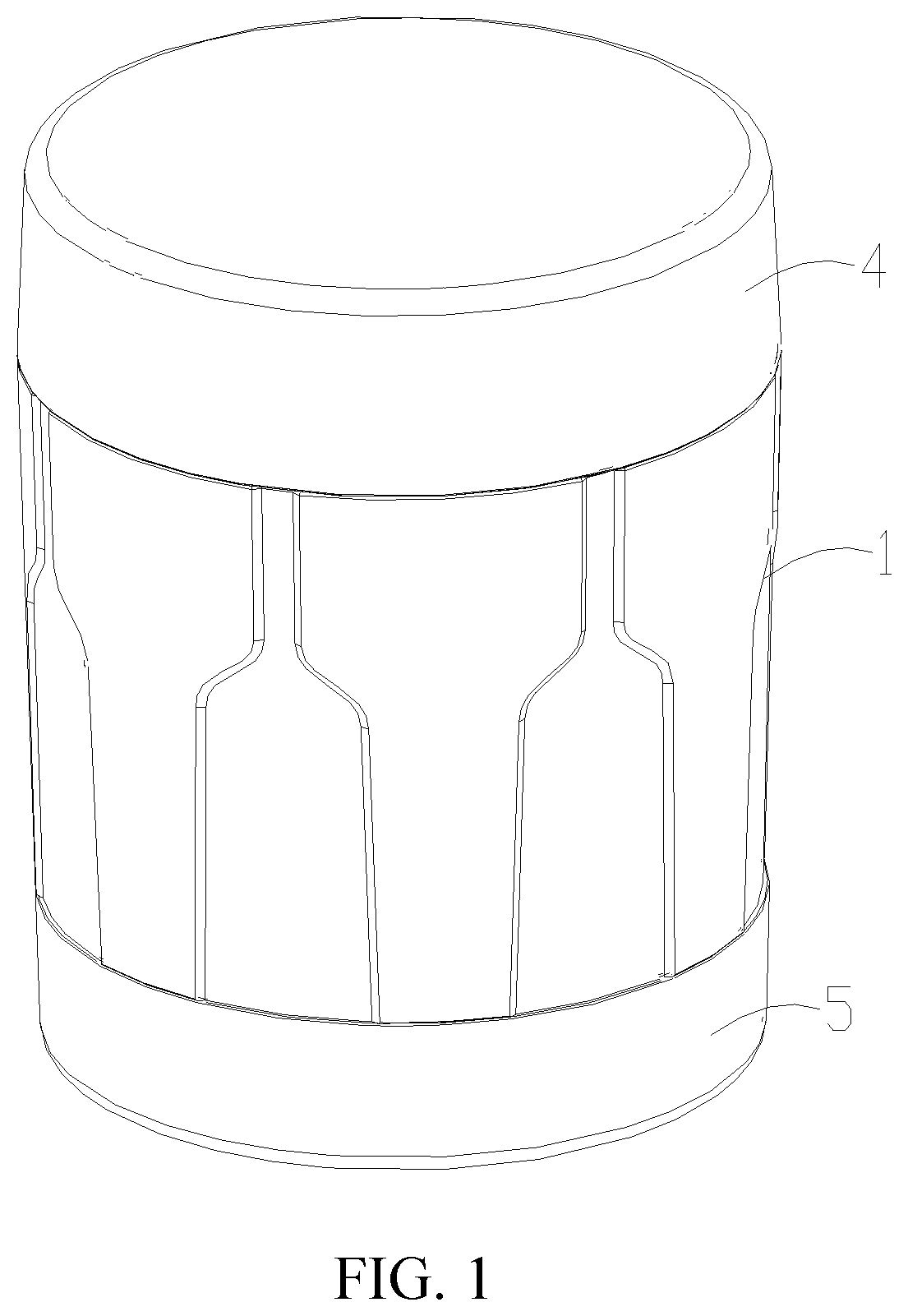
Technical solutions in the embodiments of the present disclosure will be clearly and completely described below in conjunction with the accompanying drawings in the embodiments of the present disclosure. Obviously, the described embodiments are only a part of the embodiments of the present disclosure, rather than all of the embodiments. Examples of the embodiments are shown in accompanying drawings, in which same or similar reference numerals indicate the same or similar elements or elements with the same or similar functions. The embodiments described below with reference to the drawings are exemplary, and are intended to explain the present disclosure, but should not be regarded as a limitation to the present disclosure. It should be understood that in the description of the present disclosure terms such as “central”, “lateral”, “lengthways”, “length”, “width”, “thickness”, “upper”, “lower”, “left”, “right”, “vertical”, “horizontal”, “top”, “bottom”, “inner”, “outer”, “clockwise”, “counterclockwise”, “axis”, “radial”, “circumferential”, etc., indicate direction or position relationships shown based on the drawings, and are only intended to facilitate the description of the present disclosure and the simplification of the description rather than to indicate or imply that the indicated device or element must have a specific direction or constructed and operated in a specific direction, and therefore, shall not be understood as a limitation to the present disclosure. It should be noted in the description of the present disclosure that, unless otherwise regulated and defined, terms such as “installation”, “bonded”, “connection|”, and “fix” shall be understood in broad sense, and for example, may refer to fixed connection or detachable connection or integral connection; may refer to mechanical connection or electrical connection; and may refer to direct connection or indirect connection through an intermediate medium or inner communication of two elements. For those of ordinary skill in the art, the meanings of the above terms in the present disclosure may be understood according to concrete conditions. In the present disclosure, is a structural schematic diagram of a pill dispenser of the present disclosure. is an exploded structural schematic diagram of the pill dispenser of the present disclosure. is a structural schematic diagram of a dispenser body of the present disclosure. is a structural schematic diagram of the dispenser body and a pill dispensing cover of the present disclosure. is a structural schematic diagram of the pill dispensing cover and a pill outlet cover of the present disclosure. is a structural schematic diagram of the pill outlet cover and a pushing cover of the present disclosure. is a structural schematic diagram of the pushing cover of the present disclosure. is a structural schematic diagram of the pill outlet cover of the present disclosure where a pill outlet is closed by the pushing cover. is a structural schematic diagram of the pill outlet cover of the present disclosure where the pill outlet is completely exposed. is a structural schematic diagram of the pill outlet cover of the present disclosure where the pill outlet is partially exposed. As shown in , the present disclosure provides the pill dispenser that prevent pills from tainting by other odor. The pill dispenser comprises a dispenser body 1 , a pill dispensing cover, a pill outlet cover, a top cover 4 and a bottom cover 5 . The pill dispensing cover 2 is disposed on an upper end of the dispenser body 1 . The pill outlet cover 3 is disposed on the pill dispensing cover 2 . The bottom cover 5 covers on a lower end of the dispenser body 1 . The upper cover 4 covers on the pill outlet cover 3 and is rotatably connected to the upper end of the dispenser body 1 . In one optional embodiment, as shown in , the dispenser body 1 is hollow. A fixed cylinder 1 A is disposed at a center of the dispenser body 1 . The fixed cylinder 1 A is hollow. Partition plates 1 B are connected between an outer wall of the fixed cylinder 1 A and an inner wall of the dispenser body 1 to define pill cavities 1 C. The partition plates 1 B are disposed in a circumferential array along the center of the dispenser body 1 . At least one end of each of the partition plates 1 B extends out of the dispenser body. Specifically, at least an upper end of each of the partition plates 1 B extends out of the dispenser body 1 . The upper end of each of the partition plates 1 B in the embodiment refers to one end of each of the partition plates 1 B connected to the pill dispensing cover 2 . Each of the pill cavities 1 C is defined between each two adjacent partition plates 1 B. As shown in , it is understood that two ends of each of the partition plates extend out of the dispenser body 1 . It is understood that each of the pill cavities 1 C is configured to store one specific type of pills. Therefore, the pill dispenser of the present disclosure realizes a function of storing different types of pills and the different types of pills are stored separately in the pill cavities 1 C. While a conventional pill bottle is only able to store a single type of pills. Therefore, by using the pill dispenser of the present disclosure, less pill bottles are used, which saves costs. Further, a rotating cover of a pill dispenser in the prior art is rotatably connected to a dispenser body thereof, such that a pill may be stuck between a gap between a corresponding partition plate thereof and the rotating cover. When the rotating cover is rotated, the pill may be ground and damaged, or the pill may be driven to other accommodating cavities thereof and mixed with other pill, causing the pills in other accommodating cavities being tainted by odor of the pill, affecting recognition of the pills even affecting an effectiveness of the pills. Therefore, as shown in ., the pill dispensing cover 2 and the dispenser body 1 in the embodiment are fixedly connected. Specifically, camping grooves 2 A are defined in an outer edge of a bottom portion of the pill dispensing cover 2 . A periphery of each of the partition plates 1 B is clamped in a corresponding one of the clamping grooves 2 A, so the pill dispensing cover 2 is fixed to the dispenser body 1 . In addition, a positioning column 2 B is protruded from a center of the bottom portion of the pill dispensing cover 2 , and the positioning column 3 B is inserted into an upper end of the fixed cylinder 1 A. When mounting the pill dispensing cover 2 to the dispenser body 1 , the clamping grooves 2 A are respectively aligned with the partition plates 1 B and respectively clamp the partition plates 1 B to realize fixation between the pill dispensing cover 2 and the dispenser body 1 . Therefore, the mounting of the pill dispensing cover 2 and the dispenser body 1 is very convenient. Furthermore, pill dispensing openings 2 C are defined on the pill dispensing cover 2 . The pill dispensing openings 2 C are one-to-one corresponding to the pill cavities 1 C. When the pill dispensing cover 2 is fixed to the dispenser body 1 , an end surface of each of the partition plates 1 B abuts against a bottom surface of the pill dispensing cover 2 . It is easy to understand that the pill would not be stuck, since there is no gap between the partition plates 1 B and the pill dispensing cover 2 . The pill dispensing cover 2 and the dispenser body 1 are fixed relative to each other, so the pill would not be damaged by the pill dispensing cover 2 . In addition, as shown in , the pill outlet cover 3 is rotatably connected to the pill dispensing cover 2 . The pill outlet cover 3 defines a pill outlet 3 A. The pill outlet cover 3 rotates to enable the pill outlet 3 A to communicate with any one of the pill dispensing openings 2 C. When the pill outlet cover 3 rotates, the specific type of pills in one of the pill cavities corresponding to the pill outlet 3 A is poured out from a corresponding pill dispensing opening 2 C to the pill outlet 3 A, and the specific type of pills would not fall into other pill cavities 1 C. Therefore, the pill dispenser of the present disclosure also plays a role in preventing the pills from tainting by other odour, and well ensures quality of the pills stored therein. Specifically, as shown in , an elastic positioning rib 2 D is disposed on an outer side wall of the pill dispensing cover 2 . A first positioning protrusion 2 E is disposed on one end of the elastic positioning rib 2 D. The elastic positioning rib 2 D is forced to enable the first positioning protrusion 2 E to deform in a radial direction of the pill dispensing cover 2 . The first positioning protrusion 2 E is spherical and deforms relatively from an outer edge of the first positioning protrusion 2 E toward a center thereof. The first positioning protrusion 2 E is stresses to elastically deform inwards by an external force. When the external force disappears, the first positioning protrusion 2 E resets outwards. Accordingly, positioning grooves 3 B are defined on an inner side wall of the pill outlet cover 3 . The positioning grooves 3 B are disposed in a circumferential array. The first positioning protrusion 2 E is snapped in any one of the positioning grooves 3 B to enable the pill outlet 3 A to communicate with a corresponding pill dispensing opening 3 A. The first positioning protrusion 2 E is aligned with one of the positioning grooves 3 B, and the pill outlet cover 3 is covered on the pill dispensing cover 2 along an axial direction thereof. The pill outlet cover 3 is rotated to deform the first positioning protrusion 2 E away from the one of the positioning grooves 3 B until the first positioning protrusion 2 E is snapped into a next positioning groove 3 B, so that a position of the pill outlet cover 3 relative to the pill dispensing cover 2 is fixed again. The pill outlet cover 3 is rotated, so that the pill outlet 3 A t is allowed to be communicated with any one of the pill dispensing openings to pour out different types of pills. Furthermore, plugging columns 3 C are protruded from a center of a bottom surface of the pill outlet cover 3 . The plugging columns 3 C are inserted into the positioning column 2 B and fastened to the positioning column 2 B. Specifically, the plugging columns 3 C are inserted into the positioning column 2 B and abut against an inner wall of the positioning column 2 B through interference fit. Alternatively, the plugging columns 3 C are inserted into and pass through the positioning column 2 B, and the plugging columns 3 C are snapped on an outer edge of the positioning column 2 B. Therefore, the pill dispensing cover 2 is fixed on the dispenser body 1 , and the pill outlet cover 3 is fixed on the pill dispensing cover 2 . In one optional embodiment, the pill dispenser further comprises a pushing cover 6 movably disposed on the pill outlet cover 3 . The pushing cover 6 is pushed to expose or close the pill outlet 3 A. In one optional embodiment, the pill outlet cover 3 comprises a fixed groove 3 F. The pill outlet 3 A is defined on a bottom wall of the fixed groove 3 F. The pill outlet 3 A is located on one end of the fixed groove 3 F. Sliding grooves 3 H are defined on the inner side of the fixed groove 3 F. The sliding grooves 3 H are disposed opposite to each other. Blocks 6 A are protruded from an outer side of the pushing cover 6 . The blocks 6 A are one-to-one matched with the sliding grooves 3 H. The blocks 6 A are slidable along the sliding grooves 3 H to expose or close the pill outlet 3 A. A shape of the pill outlet 3 A is circular or oval, which is not limited thereto. In the embodiment, the shape of the pill outlet 3 A is oval as one of the optional embodiments. In one optional embodiment, as shown in , a sliding portion 3 D and at least one positioning portion 3 E are defined on the fixed groove 3 F. A second positioning protrusion 6 B is disposed on a bottom portion of the pushing cover 6 (a structure of the second positioning protrusion 6 B is same as a structure of the first positioning protrusion 2 E). The second positioning protrusion 6 B is disposed on one end of the pushing cover 6 away from the pill outlet 3 A. The sliding portion 3 D and the at least one positioning portion 3 E are disposed opposite to the pill outlet 3 A. A center of the pill outlet 3 A, a center of the sliding portion 3 D; a center of the at least one positioning portion 3 E, and a center of the pill outlet cover 3 are on a same straight line. When the pushing cover 6 is pushed, the second positioning protrusion 6 B is slid in the sliding portion 3 D or is slid to be clamped in the at least one positioning portion 3 E. In the embodiment, an inner diameter of the at least one positioning portion 3 E is same as an inner width of the sliding portion 3 D. In one optional embodiment, only one positioning portion 3 E is provided. The one positioning portion 3 E is located on one side of the sliding portion 3 D close to the pill outlet 3 A. When the pushing cover 6 is pushed to enable the second positioning protrusion 6 B being clamped in the one positioning portion 3 E, the pushing cover 6 completely covers the pill outlet 3 A to close the pill outlet 3 A. When the pushing cover 6 is pushed to enable the second positioning protrusion 6 B to slide in the sliding portion 3 D, the pill outlet 3 A is partially exposed or completely exposed. Specifically, when the second positioning protrusion 6 B is slid to abut against one end of the sliding portion 3 D away from the pill outlet 3 A, the pill outlet 3 A is completely exposed. It is understood that since the second positioning protrusion 6 B is slidable in the sliding portion 3 D, when the pill dispenser is turned over to pour out the specific type of pills, a user needs to press the pushing cover to control an exposed area of the pill outlet 3 A. In one alternative embodiment, two positioning portions 3 E are provided. The positioning portions comprise a first positioning portion and a second positioning portion. The first positioning portion and the second positioning portion are respectively located on two sides of the sliding portion 3 D. The first positioning portion is disposed close to the pill outlet 3 A. The second positioning portion is disposed away from the pill outlet 3 A. When the pushing cover 6 is pushed to enable the second positioning protrusion 6 B being clamped in the one positioning portion, the pushing cover 6 completely covers the pill outlet to close the pill outlet 3 A. When the pushing cover 6 is pushed to enable the second positioning protrusion 6 B to slide in the sliding portion 3 D, the pill outlet 3 A is partially exposed. When the pushing cover 6 is pushed to enable the second positioning protrusion 6 B being clamped in the second positioning portion, the pill outlet 3 A is completely exposed. In the embodiment, the two positioning portions 3 E are symmetrically located at two sides of the sliding portion 3 D. By providing the two positioning portions 3 E, when the pill outlet 3 A is completely exposed or completely closed, the pushing cover 6 is relatively fixed on the pill outlet cover 3 . Therefore, when the pill outlet 3 A is completely exposed, the user does not need to press on the pushing cover and only needs to directly turn over the pill dispenser to pour out the pills. In one optional embodiment, sliding plates 3 G are respectively protruded from inner sides the sliding grooves 3 H. The sliding plates 3 G are disposed opposite to each other. Siding bars 6 C are disposed on a bottom portion of the pushing cover 6 . The sliding bars 6 C are parallel to each other and spaced apart from each other. The sliding bars 6 C are respectively slidable on the sliding plates 3 G. Limited by any one of the two positioning portions 3 E, the pushing cover 6 and the pill outlet cover 3 are relatively fixed to enable the pill outlet 3 A being switched between completely exposed or completely closed. Therefore, as shown in , the second positioning protrusion 6 B disposed on the pushing cover 6 is matched with the second positioning portion for positioning, so that the pushing cover 6 and the pill outlet cover 3 are relatively fixed, and the pill outlet 3 A is completely exposed. When the pill dispenser is turned over, and the second positioning protrusion is clamped in the second positioning portion, so the pushing cover 6 do not slide down nor close the pill outlet 3 A, making a process of dispensing the specific type of pills smooth. When the pushing cover 6 is forced, the second positioning protrusion 6 B deforms, enabling the pushing cover to be separated from the second positioning portion and enabling second positioning protrusion 6 B to enter the sliding portion 3 D. Then the pushing cover 6 is continuous forced to make the second positioning portion 6 B to slide in the sliding portion 3 D. As shown in , when the pushing cover 6 is pushed to enable the second positioning protrusion being clamped in the first positioning portion, the pushing cover 6 seals the pill outlet 3 A to prevent the pills from falling out and protect the pills against dust and moisture. In addition, as shown in , when the second positioning protrusion 6 B separates from any one of the two positioning portions 3 E and enters the sliding portion 3 D, the pill outlet is partially exposed. The pushing cover 6 slides to changes the exposed area of the pill outlet 3 A to control an amount of the specific type of pills poured out. If the amount of specific type of pills poured out is small, the exposed area of the pill outlet 3 A is reduced so that the specific type of pills is not poured out too much to increase a work of refilling. On the contrary, the exposed area is increased to pour more pills, so as to realize an adjustment of the amount of the specific type of pills poured out. Furthermore, as shown in a top surface of the pushing cover 6 is recessed to define a pressing groove 6 D. The pressing groove 6 D is configured for the user to put a finger thereon. When in use, the pushing cover 6 is moved and adjusted by pressing on the pressing groove 6 D with the finger. In addition, in another alternative embodiment of the pill dispenser, the elastic positioning rib is disposed on the inner side wall of the pill outlet cover, and the positioning grooves 3 B are defined on the outer side wall of the pill dispensing cover 2 (not shown in the drawings), which are flexibly disposed according to actual needs Other structures of the pill dispenser are same as the structures mentioned above. The above embodiments are only optional embodiments of the present disclosure and cannot be used to limit the protection scope of the present disclosure. Any non-substantial changes and substitutions made by those skilled in the art on the basis of the present disclosure should fall within the protection scope of the present disclosure.
Figures (7)
Citations
This patent cites (9)
- US4288006
- US5762199
- US7090072
- US7228991
- US7240795
- US8714353
- US9469451
- US10329059
- US10869578