Abstract
A sexual stimulation device includes: a main body; an elongated arm configured to be placed in a vagina, the elongate arm connected to the main body and including a first stimulation portion arranged at a distal end of the elongated arm away from the main body, the first stimulating portion configured for stimulating a first region; a second stimulation portion configured for stimulating a second region, the second region being different from the first region; and a third stimulation portion configured for stimulating a third region. The third region is different from the first stimulating region and the second stimulating region, the second stimulation portion and the third stimulation portion are respectively arranged at opposite sides of the elongated arm, a length of the second stimulation portion and a length of the third stimulation portion are shorter than a length of the elongated arm.
Claims (11)
1 . A sexual stimulation device comprising: a main body; an elongated arm configured to be placed in a vagina, the elongated arm connected to the main body and a first stimulation portion arranged at a distal end of the elongated arm away from the main body, the first stimulation portion configured for stimulating a first region; a second stimulation portion arranged at a left side of the elongated arm, wherein the second stimulation portion is capable of being placed in the vagina and configured for swinging reciprocally between a first position and a second position so as to stimulate a second region, the second region being different from the first region, the first position is at a front side of the elongated arm, the second position is at a rear side of the elongated arm; and a third stimulation portion arranged at a right side of the elongated arm, wherein the third stimulation portion is capable of being placed in the vagina and configured for swinging reciprocally between a third position and a fourth position so as to stimulate a third region, the third region being different from the first stimulation region and the second stimulating region, the third position is at the front side of the elongated arm and opposite to the first position, the fourth position is at the rear side of the elongated arm and opposite to the second position; and a driving mechanism comprising at least one driving motor configured for driving the second stimulation portion and the third stimulation portion to swing reciprocally, wherein the elongated arm, the second stimulation portion and the third stimulation portion are directly coupled to a same end of the main body and arranged along an arrange line which is parallel to a lateral direction of the sexual stimulation device, wherein the second stimulation portion, the elongated arm and the third stimulation portion at least partially overlap with one other in the lateral direction of the sexual stimulation device, while at least a part of the second stimulation portion, the elongated arm and the third stimulation portion are spaced from one another at a direction which is orthogonal to the arrange line, and wherein the elongated arm is swingable in a first swing plane perpendicular to the arrange line, the second stimulation portion is configured to swing in a second swing plane which is obliquely intersected to the first swing plane, the third stimulation portion is configured to swing in a third swing plane which is obliquely intersected to the first swing plane.
Show 10 dependent claims
2 . The sexual stimulation device according to claim 1 , wherein a first included angle defined by the first swing plane and the second swing plane ranges from greater than zero (0) degrees and no more than 60 degrees, a second included angle defined by the first swing plane and the third swing plane ranges from greater than zero (0) degrees and no more than 60 degrees, a third included angle defined by the second swing plane and the third swing plane ranges from greater than zero (0) degrees and no more than 90 degrees.
3 . The sexual stimulation device according to claim 1 , wherein the elongated arm comprises a neck portion coupled to the main body, a width of the neck portion is smaller than a width of the first stimulation portion, the neck portion comprising two concave portions at on opposite sides of the neck portion, and the second stimulation portion and the third stimulation portion are disposed beside the two concave portions.
4 . The sexual stimulation device according to claim 3 , wherein the sexual stimulation device is switchable between an original state and a pressed state, wherein in the pressed state, the second stimulation portion and the third stimulation portion are pressed towards corresponding concave portions of the two concave portions.
5 . The sexual stimulation device according to claim 4 , wherein in the original state, a maximum lateral width from the second stimulation portion to the third stimulation portion is larger than the width of the first stimulation portion, and in the pressed state, the maximum lateral width from the second stimulation portion to the third stimulation portion is substantially equal to the width of the first stimulation portion.
6 . The sexual stimulation device according to claim 1 , wherein the sexual stimulation device further comprises a control circuit arranged in the main body, the control circuit is configured to cause the sexual stimulation device to be in a first control mode or in a second control mode, wherein: in the first control mode, the second stimulation portion and the third stimulation portion swing at a same frequency in a same swing direction for a preset time period; and in the second control mode, the second stimulation portion and the third stimulation portion swing at a same frequency in opposite swing directions for a preset time period.
7 . The sexual stimulation device according to claim 1 , wherein each of the second stimulation portion and the third stimulation portion comprises a connecting end connecting with the main body and a distal end away from the main body, the distal end is rotatable around a central axis of the second stimulation portion or the third stimulation portion.
8 . The sexual stimulation device according to claim 1 , wherein each of the second stimulation portion and the third stimulation portion comprises a connecting end connecting with the main body and a distal end further away from the main body than the connecting end, at least one corresponding distal end of the second stimulation portion and the third stimulation portion comprises a vibration motor, the vibration motor is configured to drive the corresponding distal end to vibrate.
9 . The sexual stimulation device according to claim 1 , wherein the driving mechanism further comprises a transmission configured for changing rotation speeds of the driving motor, and two driver portions arranged inside the main body, the at least one driving motor is connected to the transmission, the two driver portions are configured to drive a corresponding stimulation portion of the second, and the third stimulation portions such that the second, and the third stimulation portions are driven to swing by the at least one driving motor, one end of each of the two driver portions engages with the transmission, and another end of each of the two driver portions engages with the corresponding stimulation portion.
10 . The sexual stimulation device according to claim 9 , wherein each of the second stimulation portion and the third stimulation portion comprises a cover member having a hardness less than a portion of the driving mechanism which is connected to the second stimulation portion and the third stimulation portion.
11 . The sexual stimulation device according to claim 1 , wherein the first stimulation portion of the elongated arm is movable telescopically with respect to the main body in a longitudinal direction of the sexual stimulation device.
Full Description
Show full text →
RELATED APPLICATIONS This application claims the benefit of priority to Chinese Patent Application Number 202420269198.2 filed on Feb. 2, 2024, Chinese Patent Application Number 202421779259.6 filed on Jul. 25, 2024, Chinese Patent Application Number 202421779272.1 filed on Jul. 25, 2024, Chinese Patent Application Number 202421779281.0 filed on Jul. 25, 2024, Chinese Patent Application Number 202421779288.2 filed on Jul. 25, 2024, in the China National Intellectual Property Administration. The entire contents of the above-identified application are hereby incorporated by reference.
TECHNICAL FIELD
The present disclosure relates to the technical field of sexual stimulation, in particular to a sexual stimulation device used for females.
BACKGROUND
With societal advancements, there's been a notable enhancement in living standards, leading to a heightened focus on the quality of sexual experiences. To cater to diverse sexual desires across different genders and anatomies, all kinds of sexual stimulation devices have been provided. Currently, the majority of commercially available products are handheld stimulating devices. A handheld stimulating device may include a handle and a stimulating member coupled with the handle. These devices typically have special textures on outer surfaces, unique shapes, and/or vibration members to deliver effects. However, there are also many problems, such as only a single area is being stimulated, and/or only one mode of stimulation is available, which limits the ability of the devices to provide more comprehensive or enhanced pleasurable experiences.
BRIEF DESCRIPTION OF DRAWINGS
Implementations of the present disclosure will now be described, by way of embodiment, with reference to the attached figures. is a three-dimensional structural diagram of a first embodiment of a sexual stimulation device according to the present disclosure. is an exploded view of the sexual stimulation device shown in . is an exploded view of a partial structure of the sexual stimulation device shown in . is a sectional view of the sexual stimulation device shown in . is a schematic view illustrating the sexual stimulation device shown in , in a swinging state. illustrates a view of a second stimulation portion and a third stimulation portion of the sexual stimulation device shown in , the second and the third stimulation portions being attached to an inner wall of an object. is a schematic representation of a first state of the sexual stimulation device shown in . is a schematic representation of a second state of the sexual stimulation device shown in . is a three-dimensional structural diagram of a second embodiment of a sexual stimulation device according to the present disclosure. is a sectional view of the sexual stimulation device shown in . is a three-dimensional structural diagram of a third embodiment of a sexual stimulation device according to the present disclosure. is an exploded view of the sexual stimulation device shown in . is a sectional view of a partial structure of the sexual stimulation device shown in . is a sectional view of the sexual stimulation device shown in . is a three-dimensional structural diagram of a fourth embodiment of a sexual stimulation device according to the present disclosure. is an exploded view of the sexual stimulation device shown in . is an exploded view of a partial structure of the sexual stimulation device shown in . is a sectional view of the sexual stimulation device shown in . is a three-dimensional structural diagram of a fifth embodiment of a sexual stimulation device according to the present disclosure. is a three-dimensional structural diagram of a sixth embodiment of a sexual stimulation device according to the present disclosure. is a sectional view of the sexual stimulation device shown in . is a three-dimensional structural diagram of the sexual stimulation device shown in , with a cover member being removed. is an exploded view of a partial structure of the sexual stimulation device shown in . is a partial sectional view of the sexual stimulation device shown in . is a partial enlarged view of the sexual stimulation device shown in . is a three-dimensional structural diagram of a seventh embodiment of a sexual stimulation device with a cover member being removed according to the present disclosure. is an exploded view of a partial structure of the sexual stimulation device shown in . is a sectional view of the sexual stimulation device shown in .
DETAILED DESCRIPTION
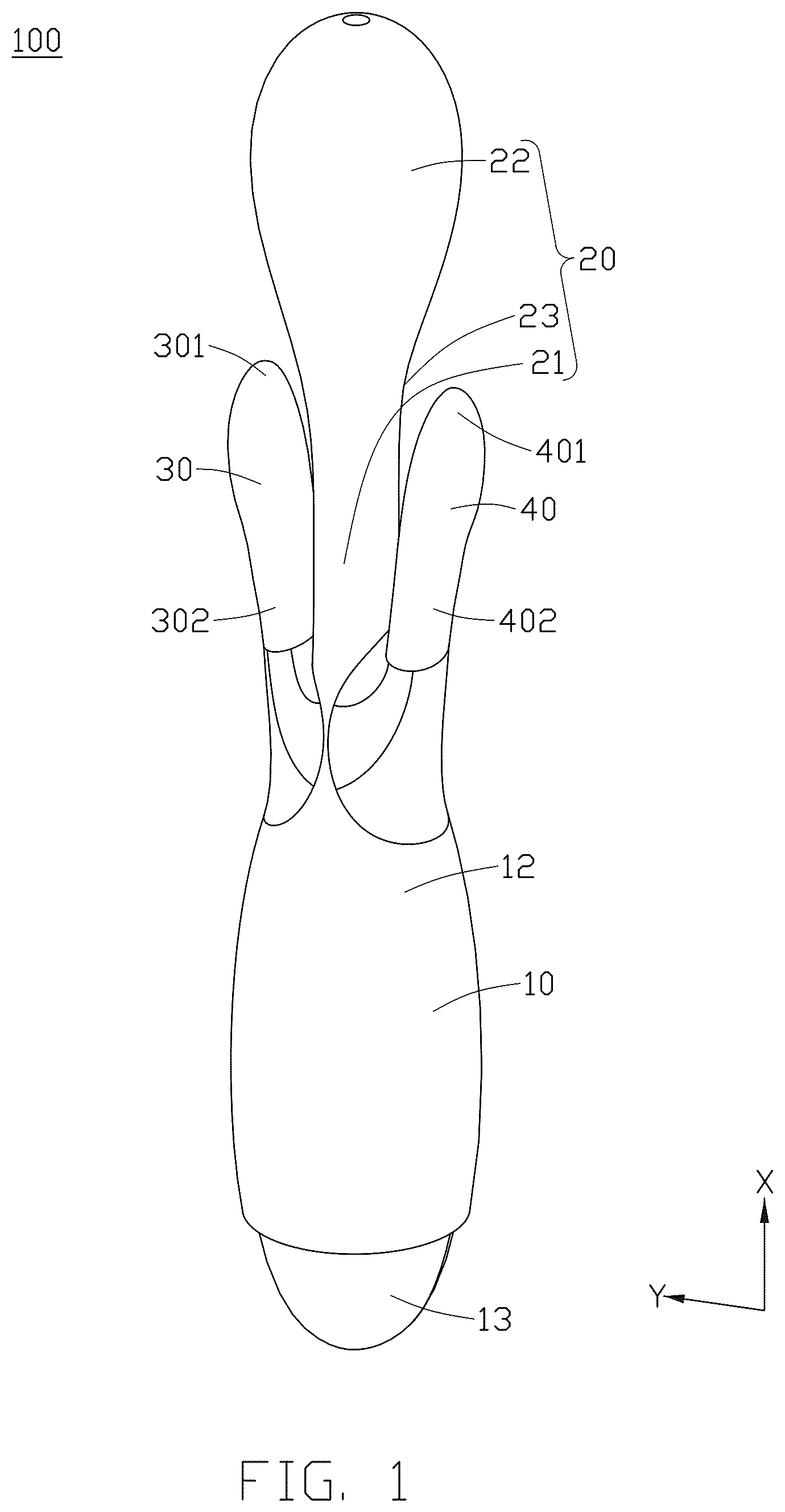
Embodiments of the present disclosure will be described in detail hereinafter with reference to the accompanying drawings. First Embodiment Referring to to to illustrate the sexual stimulation device 100 of the present disclosure. The present disclosure provides a sexual stimulation device 100 , which is configured for being partly inserted into a vagina of a female for sexual stimulation. Specifically, the sexual stimulation device 100 includes a main body 10 , an elongated arm 20 having a length direction which defines a longitudinal direction X of the sexual stimulation device 100 , a pair of stimulation portions 30 and 40 symmetrical to each other, a driving mechanism 50 , a first motor 60 , a second motor 70 , and a control circuit 101 . The main body 10 may be shaped to be easily handheld by a user in use. The elongated arm 20 and the pair of stimulation portions 30 and 40 are directly coupled to a same end of the main body 10 . Each of the elongated arm 20 and the stimulation portions 30 and 40 substantially extends along the longitudinal direction X of the sexual stimulation device 100 . The driving mechanism 50 and the control circuit 101 are accommodated in the main body 10 . The driving mechanism 50 is coupled to the elongated arm 20 , the pair of stimulation portions 30 and 40 , and the control circuit 101 , therefore, under the control of the control circuit 101 , the driving mechanism 50 is capable of driving the elongated arm 20 and the pair of stimulation portions 30 and 40 to do predefined motions. In this embodiment, the elongated arm 20 is driven to telescoping motions, and the stimulation portions 30 and 40 are driven to swing. In this embodiment, the elongated arm 20 and the pair of stimulation portions 30 and 40 are arranged along an arrange line which is parallel to a width direction of the elongated arm 20 . The width direction of the elongated arm 20 also acts as a lateral direction Y of the sexual stimulation device 100 . The pair of stimulation portions 30 and 40 includes a second stimulation portion 30 disposed at one side of the elongated arm 20 and a third stimulation portion 40 disposed at another side of the elongated arm 20 opposite to the one side of the elongated arm 20 . The second stimulation portion 30 , the elongated arm 20 and the third stimulation portion 40 at least partially overlap with one other in the lateral direction of the sexual stimulation device 100 , while at least a part of the second stimulation portion 30 , the elongated arm 20 and the third stimulation portion 40 are spaced from one another at a direction which is orthogonal to the arrange line. In one embodiment, the elongated arm 10 is swingable in a first swing plane A perpendicular to the arranged line. The second stimulation portion 30 is configured to swing in a second swing plane B which is substantially parallel to the first swing plane A. The third stimulation portion 40 is configured to swing in a third swing plane C which is substantially parallel to the first swing plane A. In one embodiment, the second stimulation portion 30 is capable of swinging in a second swing plane B which obliquely intersects with the first swing plane A. A first included angle α defined by the first swing plane A and the second swing plane B is in a range of 0-60 degrees. The third stimulation portion 40 is capable of swinging in a third swing plane C which obliquely intersects with the first swing plane A. A second included angle β defined by the first swing plane A and the third swing plane C is in a range of 0-60 degrees. A third included angle γ defined by the second swing plane B and the third swing plane C is in a range of 0-90 degrees. The main body 10 includes a first accommodating portion 11 configured for accommodating the driving mechanism 50 and the control circuit 101 . In the present embodiment, the main body 10 includes a first end 12 and a second end 13 arranged opposite to the first end 12 . The first end 12 is a free end of the sexual stimulation device 100 . The elongated arm 20 , the second stimulation portion 30 and the third stimulation portion 40 are coupled to the first end 12 of the main body 10 . In this embodiment, the main body 10 is roughly elliptical in shape and has a handheld portion configured for being held by a hand of the female. In addition, the main body 10 further includes a button (not shown), which is configured for controlling the control circuit 101 of the sexual stimulation device 100 . In the present embodiment, the elongated arm 20 is connected to the main body 10 and includes a connecting portion 21 extending from the first end 12 of the main body 10 and a first stimulation portion 22 extending from one end of the connecting portion 21 away from the main body 10 . The first stimulation portion 22 is configured to stimulate a first region 201 of the female. When the elongated arm 20 is inserted into the vagina of the female, the elongated arm 20 can massage and stimulate the first region 201 of the vagina by the first stimulation portion 22 , thereby obtaining a better sexual experience. Especially, compared to an opening of the vagina, the first region is much closer to a deepest side of the vagina. In one embodiment, the length of the elongated arm 20 is in a range of 3 cm to 30 cm, which can be exemplified as 3 cm, 5 cm, 8 cm, 10 cm, 15 cm, 20 cm, 25 cm, 30 cm and the like, which is not limited herein. In this embodiment, referring to and , the connecting portion 21 comprises a neck portion 23 coupled to the main body 10 , a width W 1 of the neck portion 23 is much smaller than the width W 2 of the first stimulation portion 22 . The neck portion 23 comprising two concave portions 231 at on two opposite sides of the neck portion 23 . The second stimulation portion 30 and the third stimulation portion 40 are disposed beside the two concave portions 231 . In this embodiment, the second stimulation portion 30 and the third stimulation portion 40 are disposed at the two opposite sides of the neck portion 23 beside the concave portions 231 . The sexual stimulation device 100 is switchable between an original state and a pressed state, in the pressed state, the second stimulation portion 30 and the third stimulation portion 40 are pressed towards the corresponding concave portions 231 . In the original state, a maximum lateral width W 3 from the second stimulation portion 30 to the third stimulation portion 40 is larger than the width W 2 of the first stimulation portion 22 . When the elongated arm 20 is being inserted into the vagina, the second stimulation portion 30 and the third stimulation portion 40 are pressed and at least partially accommodated in the corresponding concave portions 23 , such that the second stimulation portion 30 and the third stimulation portion 40 are changed into the pressed state. In the pressed state, the maximum lateral width W 3 from the second stimulation portion 30 to the third stimulation portion 40 is substantially equal to the width W 2 of the first stimulation portion 22 . The elongated arm 20 further comprises a second accommodating portion 24 formed at the first stimulation portion 22 configured for accommodating the first motor 60 . The first motor 60 drives the first stimulation portion 22 to move, such as vibration, rotation, extension, flowing, hollowing out and other different movements by control of the control circuit 101 . When the elongated arm 20 is inserted into the vagina, the elongated arm 20 can further stimulate the first region 201 of the vagina of the female. In the present embodiment, the first motor 60 is provided with a battery (not shown) configured to supply power to the first motor 60 . The battery is also received in the second accommodating portion 24 . Therefore, it is possible to effectively simplify the wiring inside the sexual stimulation device 100 and save space. Referring to to , each of the second stimulation portion 30 and the third stimulation portion 40 extend from the main body 10 along a direction parallel to or obliquely intersected with the longitudinal direction X of the sexual stimulation device 100 . The second stimulation portion 30 and the third stimulation portion 40 are arranged at opposite sides of the elongated arm 20 , a length of the second stimulation portion 30 and a length of the third stimulation portion 40 are much shorter than a length of the elongated arm 20 , the second stimulation portion 30 is configured for stimulating a second region 301 of the female, the second region 301 is different from the first region 201 , the third stimulation portion 40 is configured for stimulating a third region 401 of the female, the third region 301 is different from the first region 201 and the second region 301 . The elongated arm 20 is arranged between the second region 301 and the third region 401 . In the present embodiment, a length of the elongated arm 20 is much greater than at least one of a length of the second stimulation portion 30 and a length of the third stimulation portion 40 . For example, the length of the elongated arm 20 is more than twice of each of the lengths of the second stimulation portion 30 and the third stimulation portion 40 . In the present embodiment, the lengths of the second stimulation portion 30 and the third stimulation portion 40 are in a range of ¼ to ½ of the length of the elongated arm 20 . An end of the elongated arm 20 that is most further away from the main body 10 relative to at least one end of the second and third stimulation portions 30 , 40 is insertable into a deep position inside the vagina, the at least one end of the second and third stimulation portions 30 , 40 is deposed at an area adjacent to an opening of the vagina. That is, the second region 301 and the third region 401 (shown in ) are adjacent to the opening of the vagina, while the first region 201 is adjacent to the deepest area of the vagina. In a use circumstance, the elongated arm 20 inserts into the vagina to stimulate, the second stimulation portion 30 and the third stimulation portion 40 are also insert into the vagina together with the elongated arm 20 . In this use circumstance, the second region 301 and the third region 401 are in the vagina of the female (shown in ). In another using circumstance, the elongated arm 20 inserts into the body, the second stimulation portion 30 and the third stimulation portion 40 abut the periphery of the vagina. In this use circumstance, the second region 301 and the third region 401 are located at outside of the vagina (as shown in ). Users can thus obtain a better massage stimulation effect. In addition, the second stimulation portion 30 and the third stimulation portion 40 are configured to swing. The control circuit 10 is configured to cause the sexual stimulation device 100 to be in a first control mode or in a second control mode. in the first control mode, the second stimulation portion 30 and the third stimulation portion 40 swing at a same frequency in a same swing direction for a preset time period, in the second control mode, the second stimulation portion 30 and the third stimulation portion 40 swing at a same frequency in opposite swing directions for a preset time period. In some embodiments, the second stimulation portion 30 and the third stimulation portion 40 are configured to swing reciprocally relative to the elongated arm 20 such that the second and the third stimulation portions 30 , 40 move closer to or further from the elongated arm 20 . The second stimulation portion 30 and the third stimulation portion 40 can predefined to swing in a same direction at a certain time, such as, both of them swinging towards left, or predefined to swing in opposite directions at a certain time, such as, the second stimulation portion 30 swinging towards left while the third stimulation portion 40 swinging towards right. In this embodiment, the second stimulation portion 30 and the third stimulation portion 40 are swingable along a thickness direction Z. Specifically, the second stimulation portion 30 and the third stimulation portion 40 are predefined to swing synchronously. The second stimulation portion 30 and the third stimulation portion 40 swing towards a same direction or opposite directions at a certain time. In other embodiments, each of the second stimulation portion 30 and the third stimulation portion 40 includes a connecting end 301 , 401 connecting with the main body 10 and a distal end 302 , 402 away from the main body 10 . The distal end 302 , 402 is rotatable around a central axis thereof. In addition, at least one of the distal ends 302 , 402 of the second stimulation portion 30 and the third stimulation portion 40 is provided with the second motor 70 . The second motor 70 is configured to drive the corresponding distal end 302 , 402 to vibrate. In this way, the second/third stimulation portion 30 / 40 having the second motor 70 vibrate while swinging, thereby providing the user with a better experience. In this embodiment, each of the second stimulation portion 30 and the third stimulation portion 40 is provided with the second motor 70 . In the present embodiment, the second motor 70 is a vibration motor capable of generating vibrations in a high frequency. In the present embodiment, the second motor 70 has a battery (not shown) in the distal end for supplying power to the second motor 70 . Thereby effectively simplifying the wirings inside the sexual stimulation device 100 . In this embodiment, each of the second stimulation portion 30 and the third stimulation portion 40 has a roughly columnar structure. Referring to to , the driving mechanism 50 includes a driving motor 51 , a transmission 52 and two driver portions 53 arranged in the first accommodating portion 11 . The driving motor 51 is connected to the transmission 52 configured for changing rotation speeds of the driving motor 51 , thereby controlling the frequency of the elongated arm 20 , the second stimulation portion 30 and the third stimulation portion 40 . the two driver portions 53 are configured to drive the corresponding stimulation portion to move by the drive of the driving motor 51 , one end of each of the two driver portions 53 engages with the transmission 52 , and another end of each of the two driver portions 53 is inserted into corresponding one of the second stimulation portion 30 and third stimulation portion 40 , so as to drive the second stimulation portion 30 and the third stimulation portion 40 to move by the drive of the driving motor 51 . In this way, by driving the second stimulation portion 30 and the third stimulation portion 40 to swing under the effect of one driving motor 51 , thereby satisfying driving mechanisms 50 . The sexual stimulation device 100 further includes a cover member 90 having a hardness less than the two driver portions 53 . In this embodiment, a portion of the cover member 90 corresponding to the elongated arm 20 , the second stimulation portion 30 and/or the third stimulation portion 40 is seamless so as to provide one continuous skin-like surface that is smooth and soft. In this embodiment, each of the second two stimulation portion 30 and the third stimulation portion 40 comprises the cover member 90 having a hardness less than a portion of the driving mechanism 50 which is connected to the second stimulation portion 30 and the third stimulation portion 40 . In the present embodiment, the second end 12 of the main body 10 is exposed from the cover member 90 . In another words, an outer surface of the second end 12 of the main body 10 is not wrapped by the cover member 90 . In other embodiments, the cover member 90 can also wrap the entire surface of the main body 10 , which is not limited herein. A recess 15 is formed in an outer surface of the main body 10 at a location adjacent to the second end 12 . A protruding portion 92 is formed at an end of the cover member 90 . The protruding portion 92 is received into the recess 15 to further prevent the cover member 90 from detaching from the main body 10 . In addition, the sexual stimulation device 100 further includes a shell 80 having a hardness larger than that of the cover member 90 . At least one of the first accommodating portion 11 and the second accommodating portion 24 are defined by the shell 80 . The cover member 90 covers the shell 80 at the second stimulation portion 30 and the third stimulation portion 40 . Second Embodiment The second embodiment of the present disclosure will be illustrated below based on and . In addition, for the convenience of illustration, the same reference numerals are marked for components with the same function as those described in the above embodiments, and their illustrations are omitted. In the present embodiment, a connecting portion 21 A of the elongated arm 20 A of the sexual stimulation device 100 B is roughly cylindrical. The size of the connecting portion 21 A is slightly less than that of a first stimulation portion 22 A. A neck portion 23 A is formed between the connecting portion 21 A and the first stimulation portion 22 A. A top end of the elongated arm 20 A is higher than each one of a top end of the second stimulation portion 30 A and the third stimulation portion 40 A. The second stimulation portion 30 A and the third stimulation portion 40 A are asymmetrically arranged. The length of the second stimulation portion 30 A is different to that of the third stimulation portion 40 A. In the present embodiment, the second stimulation portion 30 A and the third stimulation portion 40 A protrude from different positions, and the second stimulation portion 30 A and the third stimulation portion 40 A are bent, the end of the third stimulation portion 40 A away from the main body 10 A is closer to the elongated arm 20 A than a middle portion of the third stimulation portion 40 A. Further, the third stimulation portion 40 A includes a plurality of spherical portions 41 which are sequentially connected. The sizes of the plurality of spherical portions 41 are gradually decreased the side adjacent to the main body 10 A. In this embodiment, the main body 10 A further comprises a decorative member 102 to improve the overall appearance of the sexual stimulation device 100 A. In this embodiment, the cover member 90 A is arranged at the out surface of the sexual stimulation device 100 A, except for the decorative member 102 , to make the outer surface of the sexual stimulation device 100 A soft and obtain a better experience. Third Embodiment The third embodiment of the present disclosure will be illustrated below based on to . In addition, for the convenience of illustration, the same reference numerals are marked for components with the same function as those described in the above embodiments, and their illustrations are omitted. In the present embodiment, the main body 10 B of the sexual stimulation device 100 B includes the first end 12 B and the second end 13 B arranged opposite to the first end 12 B. The main body 10 B may be hemispherical shape which has gradually decrease size from the first end 12 B and the second end 13 B. The elongated arm 20 B of the present embodiment may be roughly in a shape of a water droplet, and the maximum size of the first stimulation portion 22 B is greater than the size of the connecting portion 21 B. The sexual stimulation device 100 B of the present embodiment further includes a connecting rod 61 extending from the main body 10 B to the elongated arm 20 B for supporting the elongated arm 20 B. In the present embodiment, the second stimulation portion 30 B and the third stimulation portion 40 B are arranged on the first end 12 B of the main body 10 B, with a cross section being cone-shaped, and no motor is arranged inside the second stimulation portion 30 B and the third stimulation portion 40 B. The oscillations generated by the second stimulation portion 30 B and the third stimulation portion 40 B are caused by the driving effects of the driver portion 53 B of the driving mechanism 50 B. In the present embodiment, the sexual stimulation device 100 B further includes an edge portion 62 of the first end 12 B of the main body 10 B. The extension direction of the edge portion 62 is the same as the extension directions of the second stimulation portion 30 B and the third stimulation portion 40 B. In this embodiment, the edge portion 62 extends along the side wall of the first end 12 B of the main body 10 B. The first ends 12 B forms a groove 63 , the elongated arm 20 B, the second stimulation portion 30 B and the third stimulation portion 40 B extend from a bottom 64 of the groove 63 . In the present embodiment, a protrusion height of the edge portion 62 is less than a protrusion height of the second stimulation portion 30 B and the third stimulation portion 40 B. Therefore, the edge portion 62 will not hinder the movement of the elongated arm 20 B, the second stimulation portion 30 B and the third stimulation portion 40 B. Herein, the protrusion height of the edge portion 62 refers to the length of the edge portion 62 extending from the end wall of the first end 12 B of the main body 10 B, while the protrusion heights of the second stimulation portion 30 B and the third stimulation portion 40 B refer to the length of the second stimulation portion 30 B and the third stimulation portion 40 B extending from the end wall of the first end 12 B of the main body 10 B. The driving motor 51 B, the transmission 52 B, and the two driver portions 53 B of the driving mechanism 50 B are arranged in the first accommodating portion 11 B, and their structures have been adjusted accordingly based on the appearance of the sexual stimulation device 100 B. In addition, the cover member 90 B is wrapped around the outer circumference of the shell 80 B and the two driver portions 53 B, that is, the cover member 90 B is wrapped around the overall outer circumference of the sexual stimulation device 100 B, thereby having better sealing performance. Fourth Embodiment The fourth embodiment of the present disclosure will be illustrated below based on to . In addition, for the convenience of illustration, the same reference numerals are marked for components with the same function as those described in the above embodiments, and their illustrations are omitted. In the sexual stimulation device 100 C of the present embodiment, the elongated arm 20 C further comprises a non-linear portion 24 C arranged between the first stimulation portion 22 C and the connecting portion 21 C of the elongated arm 20 C and configured for providing necessary space for expansion and contraction movements of the elongated arm 20 C. In addition, the second stimulation portion 30 C and the third stimulation portion 40 C cooperatively form as an upper edge of one end of the main body 10 C. The second stimulation portion 30 C and the third stimulation portion 40 C encircle the elongated arm 20 C with most of the elongated arm 20 C extending out of the he second stimulation portion 30 C and the third stimulation portion 40 C along the length direction of the elongated arm 20 C. Each of the second stimulation portion 30 C and the third stimulation portion 40 C comprises a cavity 33 , a second motor 70 C is provided in the cavity 33 to drive the second/third stimulation portion 30 C/ 40 C to vibrate. In this way, the second stimulation section 30 C and the third stimulation section 40 C also have a vibration function while swinging, thereby obtaining better experience. In the present embodiment, the second stimulation portion 30 C and the third stimulation portion 40 C are not separated with each other. The lateral edges of the second stimulation portion 30 C are seamlessly connected with lateral edges of the third stimulation portion 40 C. That is, the majority of both the second stimulation portion 30 C and the third stimulation portion 40 C are continuous, with only a minor portion being discrete. Only one second motor 70 C is arranged to drive the vibrations of the second stimulation portion 30 C and the third stimulation portion 40 C. In use, both of the second stimulation portion 30 C and the third stimulation portion 40 C move towards the elongated arm 20 C at a certain time. Afterwards, both of the second stimulation portion 30 C and the third stimulation portion 40 C move away from the elongated arm 20 C at another certain time. The second stimulation portion 30 C and the third stimulation portion 40 C thus may simulate movements of human's lips. In the present embodiment, the driving mechanism 50 C further includes a driving rod 54 and a connecting rod 55 . The driving rod 54 is arranged in the first accommodating portion 11 C and connected with the driving motor 51 C. The connecting rod 55 extends into the elongated arm 20 C to support the elongated arm 20 C and control the contraction and expansion of the elongated arm 20 C. Fifth Embodiment The fifth embodiment of the present disclosure will be illustrated below based on . In addition, for the convenience of illustration, the same reference numerals are marked for components with the same function as those described in the above embodiments, and their illustrations are omitted. In the present embodiment, the sexual stimulation device 100 D includes a groove 63 D defined at an end surface of the main body 10 D. A plurality of stimulation portions 30 D and the elongated arm 20 D are arranged on a bottom wall 64 D of the groove 63 D. The plurality of stimulation portions 30 D are arranged in a plurality circles. The stimulation portions 30 D between adjacent circles offset to each other. When the sexual stimulation device 100 D is in operation, at least some of the plurality of stimulation portions 30 D swing towards the elongated arm 20 D at a certain time, and then move away from the elongated arm 20 D at another certain time, such that the plurality of stimulation portions 30 D can be contracted and expanded like petals. In other embodiments, a plurality of stimulation portions 30 D are capable of auto-rotation, vibration and performing other movements. In addition, an end of the edge portion 63 D away from the main body 10 D is arranged in a non-linear manner, to improve aesthetics. Sixth Embodiment The sixth embodiment of the present disclosure will be illustrated below based on to . In addition, for the convenience of illustration, the same reference numerals are marked for components with the same function as those described in the above embodiments, and their illustrations are omitted. In the sexual stimulation device 100 E of the present embodiment, the elongated arm 20 E includes a connecting portion 21 E and a first stimulation portion 22 E connected to the connecting portion 21 E. In the present embodiment, the second stimulation portion 30 E and the third stimulation portion 40 E are provided spaced apart from the connecting portion 21 E. When the elongated arm 20 E swings along a first plane, the second stimulation portion 30 E and the third stimulation portion 40 E swing towards and spaced apart from the elongated arm 20 E along a second plane which is perpendicular to the first plane. In this embodiment, each of the second stimulation portion 30 E and the third stimulation portion 40 E includes a driver portion 55 E, and details of the driver portions 55 E will be described later. Referring to to , the driving mechanism 50 E includes a driving motor 51 E, a fixing portion 52 E, a screw 53 E, and a pushing assembly 54 E. The driving motor 51 E includes a rotating shaft 511 extended from one end of the driving motor 51 E along the longitudinal direction X of the sexual stimulation device 100 E. The rotating shaft 511 can rotate under the drive of the driving motor 51 E. The rotating shaft 511 includes a shaft portion 5111 and a bending portion 5112 . The bending portion 5112 is provided at one end of the shaft portion 5111 away from the driving motor 51 E and forms an included angle α with the shaft portion 5111 (see ). Further, the angle α between the bending portion 5112 and the shaft portion 5111 is in a range from 3 degrees to 60 degrees, so that the first stimulation portion 22 E is inclined at a predetermined angle relative to the connecting portion 21 E, and rotates within a corresponding angle range, thereby facilitating control of the elongated arm 20 E to swing within a preferable range. The fixing portion 52 E is fixedly disposed at an end of the bending portion 5112 away from the shaft portion 5111 , and fixedly disposed in the elongated arm 20 E, so as to drive the first stimulation portion 22 E of the elongated arm 20 E to rotate around the extending direction of the elongated arm 20 E when the driving motor 51 E drives the rotating shaft 511 to rotate. In this embodiment, the bending portion 5112 forms the third included angle θ with the shaft portion 5111 , and when the driving motor 51 E is started, the rotating shaft 511 rotates and drives the bending portion 5112 to rotate and swing, the stimulation portion 22 E can rotate and swing following the bending portion 5112 . The screw 53 E is fastened at an end of the shaft portion 5111 adjacent to the driving motor 51 E. An outer circumferential surface of the screw 53 E is provided with a helical groove 531 , and an abutting portion 532 is provided in the helical groove 531 . The pushing assembly 54 E is movably arranged on the screw 53 and includes a first pusher 541 and a second pusher 542 . The first pusher 541 includes a first through hole 5411 arranged at a substantially central portion thereof and a first recess 5412 (see ) recessed from an inner wall of the first through hole 5411 . The second pusher 542 includes a second through hole 5421 and a second recess 5422 recessed from an inner wall of the second through hole 5421 . The first through hole 5411 is aligned with the second through hole 5421 to form a through hole for a screw to pass therethrough. The first recess 5412 and the second recess 5422 cooperate to form a groove for accommodating the abutting portion 532 (see ). In this way, a part of the abutting portion 532 is accommodated in the groove, and another part of the abutting portion 532 is accommodated in the helical groove 531 . Thus, when the driving motor 51 is started, the screw 53 E rotates along with the rotation of the rotating shaft 511 E, and the abutting portion 532 moves along the helical groove 531 , simultaneously driving the pushing assembly 54 E to reciprocate along a length direction of the screw 53 . An end of each driver portion 55 E is rotatably connected to an end of the pushing assembly 54 E, and another end of each driver portion 55 E extends into the corresponding one of the second stimulation portion 30 E and the third stimulation portion 40 E. Each driver portion 55 E includes a first driver portion 551 , an intermediate portion 552 and a second driver portion 553 which are arranged in sequence, and an obtuse angle is formed between the first driver portion 551 and the second driver portion 553 . The first driver portion 551 is rotatably connected to the pushing assembly 54 E by a connecting shaft 554 . When the pushing assembly 54 E moves towards the main body 10 , the second driver portions 553 move towards the elongated arm 20 E. When the pushing assembly 54 E moves away from the main body 10 , the second driver portions 553 move away from the elongated arm 20 E and perform reciprocating swinging motion. Both sides of the middle portion 552 are provided with a rotating shaft 5521 , and each transmission 55 E is rotatably arranged on the shell 80 by the rotating shaft 5521 . Therefore, under the driving of the driving motor 51 E, the second stimulation portion 30 E and the third stimulation portion 40 E can swing with the corresponding driver portion 55 E, and the elongated arm 20 E can perform swinging motion with the pushing assembly 54 E. Seventh Embodiment Referring to to , the first stimulation portion 22 F of the elongated arm 20 F is movable telescopically with respect to the main body 10 F in a longitudinal direction of the sexual stimulation device 100 F under the driving of the driving mechanism 50 F. In this embodiment, the shell 80 F has a T-shaped structure. The shell 80 F includes a horizontal portion 81 and a vertical portion 82 perpendicular to the horizontal portion 81 . Referring to to , the driving mechanism 50 F is arranged in the vertical portion 82 , and the driving mechanism 50 F includes a driving motor 51 F, a screw 53 F, a pushing member 55 F, and an abutting member 56 F. The driving motor 51 F includes a rotating shaft 511 F, and the rotating shaft 511 F extends from an end of the driving motor 51 F along the longitudinal direction X of the sexual stimulation device 100 F and is capable of rotating under the action of the driving motor 51 F. In this embodiment, the driving motor 51 F is a decelerating motor. The screw 53 F is fixedly disposed on the rotating shaft 511 F and rotates along with rotation of the rotating shaft 511 F. A spiral groove 531 F is formed in an outer peripheral surface of the screw 53 F. The push assembly 54 F is movably disposed on the screw 53 F. Specifically, the push assembly 54 F includes a first pusher 541 F and two second pushers 542 F. The first pusher 541 F is located at a side adjacent to the first stimulation portion 22 F and sleeved on the screw 53 F, and the first stimulation portion 22 F is sleeved on the first pusher 541 F and configured for pushing the first stimulation portion 22 F of the elongated arm 20 F to perform a telescopic movement relative to the connecting portion 21 F. The two second pushers 542 F extend from a peripheral edge of one side of the first pusher 541 F away from the first stimulation portion 22 F to the main body 10 F. The two second pushers 542 F are configured for surrounding the driving motor 51 F and rotatably connected to the corresponding driver portions 57 , respectively, so as to drive the second stimulation portion 30 F and the third stimulation portion 40 F to swing relative to the main body 10 F. In this embodiment, the second pushers 542 F includes two pusher rods 543 F, the two pusher rods 543 F are configured to surround the driving motor 51 F and rotatably connected to the corresponding driver portion 55 F, respectively. One end of the abutting member 56 F is fixedly arranged on the first pushing member 551 F, and the other end of the abutting member 56 F is accommodated in the spiral groove 531 . When the screw 53 F rotates along with the rotation shaft 511 F of the driving motor 51 F, the abutting member 56 F moves along the spiral groove 531 , thereby driving the pushing member 55 F to move in the extension direction of the screw 53 F, so that the movement portion 22 F can be driven to extend and retract. In this embodiment, the elongated arm 20 F further includes a pleat portion 25 , the pleat portion 25 is arranged at the end of the elongated arm 20 F adjacent to the main body 10 F and configured for providing necessary space for expansion and contraction movements of the elongated arm 20 F. When the swing driving device 100 F operates, the screw 53 F rotates along with the rotation of the rotating shaft 511 F, the abutting member 56 F moves along the spiral groove 531 while driving the pushing member 55 F to move along the lengthwise direction X of the sexual stimulation device 100 F. When the push assembly 54 F moves towards the elongated arm 20 F, the elongated arm 20 F is pushed to move in a direction away from the main body 10 F. That is, the elongated arm 20 F is in an extended state, and at this time, the second pushers 542 F are also moved towards the first stimulation portion 22 F, the driver portion 55 moves away from elongated arm 20 F. When the push assembly 54 F moves towards the main body 10 F, the elongated arm 20 F is pulled to move towards the main body 10 F, that is, the telescopic portion 20 F is retracted, and at this time, the second pushers 542 F move away from the elongated arm 20 F. When the elongated arm 20 F performs the reciprocating telescopic movement, the second stimulation portion 30 F and the third stimulation portion 40 F swings reciprocally, thereby realizing the meshing movement.
Figures (20)
Citations
This patent cites (13)
- US9138373
- US12208053
- US2006/0141903
- US2007/0149903
- US2014/0323929
- US2015/0141883
- US2015/0182413
- US2016/0051438
- US2016/0120737
- US2016/0166466
- US2017/0100303
- US2018/0161236
- US2024/0325240