Abstract
An image forming device, including: a drawer movable from an inside position where the drawer is located inside a housing to an outside position where the drawer is located outside the housing via an intermediate position; a stopper movable between a first position where the stopper stops the drawer from moving from the intermediate position to the outside position and a second position where the stopper allows the drawer to move from the intermediate position to the outside position; a drum cartridge mountable on the drawer; and a toner cartridge mountable on the drawer; wherein the toner cartridge mounted on the drawer is detachable from the drawer in a state in which the drawer is located at the intermediate position, and wherein the drum cartridge mounted on the drawer is detachable from the drawer in a state in which the drawer is located at the outside position.
Claims (8)
1 . An image forming device, comprising: a housing: a drum cartridge including a photoconductive drum and a developer roller; and a toner cartridge storing toner; wherein, in a state in which the drum cartridge and the toner cartridge are connected to each other, the drum cartridge and the toner cartridge are movable in a first direction from an inside position at which the toner cartridge is located inside the housing to an outside position at which the toner cartridge is located outside the housing, wherein the toner cartridge includes a toner storage portion storing the toner and a toner supply portion capable of supplying the toner to the drum cartridge in the state in which the drum cartridge and the toner cartridge are connected to each other, the toner supply portion being located at a most downstream portion of the toner cartridge in a direction from the outside position to the inside position, wherein the drum cartridge includes a connection portion connected to the toner supply portion in the state in which the drum cartridge and the toner cartridge are connected to each other, wherein the toner supply portion includes a discharge opening from which the toner is discharged, wherein the toner cartridge includes a first shutter movable between a first closing position at which the first shutter closes the discharge opening and a first open position at which the first shutter opens the discharge opening, wherein the connection portion includes an inlet opening through which the toner discharged from the discharge opening of the toner cartridge is received, wherein the drum cartridge includes a second shutter movable between a second closing position at which the second shutter closes the inlet opening and a second open position at which the second shutter opens the inlet opening, wherein the toner cartridge includes a handle having an arm and a toner grip connected to one end of the arm, the other end of the arm is located nearer to the toner supply portion than the one end, and the handle is pivotable about an axis extending in a second direction through the other end, the second direction intersecting the first direction and being parallel to a direction in which the photoconductive drum extends, wherein the handle is pivotable between: a handle first position at which the handle causes the first shutter to be located at the first closing position and causes the second shutter to be located at the second closing position; and a handle second position at which the handle causes the first shutter to be located at the first open position and causes the second shutter to be located at the second open position, and wherein the arm extends in the first direction when the handle is located at the handle second position and the arm extends in a direction intersecting the first direction when the handle is located at the handle first position, so that the toner grip is located more distant from the toner storage portion when the handle is located at the handle first position than when the handle is located at the handle second position.
Show 7 dependent claims
2 . The image forming device according to claim 1 , wherein the toner cartridge is attachable to and detachable from the drum cartridge when the handle is located at the handle first position, and the toner cartridge is unattachable to and undetachable from the drum cartridge when the handle is located at the handle second position.
3 . The image forming device according to claim 2 , wherein the drum cartridge includes a pair of drum cartridge side plates apart from each other in an axis direction of the drum cartridge, wherein the pair of drum cartridge side plates includes a pair of guides, wherein the second shutter includes a pair of shutter end plates, wherein the pair of shutter end plates includes a pair of grooves, wherein the toner cartridge includes a pair of guided portions configured to be guided by the pair of guides toward the pair of grooves, wherein, when the handle is located at the handle first position in a state in which the guided portions engage the grooves, the first shutter is located at the first closing position while the second shutter is located at the second closing position, and the guides and the grooves are connected to each other, and wherein, when the handle is located at the handle second position in the state in which the guided portions engage the grooves, the first shutter is located at the first open position while the second shutter is located at the second open position, and the guides and the grooves are not connected to each other.
4 . The image forming device according to claim 1 , wherein, when the drum cartridge and the toner cartridge are located at the inside position, the handle is prevented from moving from the handle second position to the handle first position, and wherein, when the drum cartridge and the toner cartridge are located at the outside position, the handle is allowed to move from the handle second position to the handle first position.
5 . The image forming device according to claim 1 , further comprising a drawer on which the drum cartridge and the toner cartridge are mounted, wherein the drawer is movable from a drawer inside position at which the drum cartridge and the toner cartridge are located at the inside position to a drawer outside position at which the drum cartridge and the toner cartridge are located at the outside position via an intermediate position between the drawer inside position and the drawer outside position.
6 . The image forming device according to claim 5 , wherein the drawer includes a locking portion at which the drum cartridge is locked with respect to the drawer in a state in which the drum cartridge is mounted on the drawer.
7 . The image forming device according to claim 6 , wherein the drawer includes a locking lever movable between a lock position at which the drum cartridge is locked at the locking portion and an unlock position at which the drum cartridge is unlocked from the locking portion, wherein the locking lever is located inside the housing when the drawer is located at the intermediate position, and wherein the locking lever is located outside the housing when the drawer is located at the drawer outside position.
8 . The image forming device according to claim 7 , wherein the drum cartridge includes a locked portion configured to engage the locking portion.
Full Description
Show full text →
CROSS REFERENCE TO RELATED APPLICATION
The present application is a Continuation Application of U.S. Ser. No. 18/066,501, filed Dec. 15, 2022, now U.S. Pat. No. 12,105,456, which is a Continuation Application of U.S. Ser. No. 17/554,263, filed Dec. 17, 2021, now U.S. Pat. No. 11,556,085, which is a Continuation Application of U.S. Ser. No. 17/003,068, filed Aug. 26, 2020, now U.S. Pat. No. 11,231,674, which claims priority from Japanese Patent Application No. 2019-159904, which was filed on Sep. 2, 2019, the disclosures of which are herein incorporated by reference in their entirety.
BACKGROUND
Technical Field The following disclosure relates to an image forming device. Description of Related Art An image forming device conventionally includes a housing, a drawer, and a process cartridge. The drawer is movable between an inside position at which the drawer is located inside the housing and an outside position at which the drawer is located outside the housing. The process cartridge is mountable on the drawer. The process cartridge includes a photoconductive drum and a developer roller. The process cartridge is capable of storing toner.
SUMMARY
The process cartridge of the known image forming device includes the photoconductive drum and the developer roller as described above. When the amount of the toner remaining in the process cartridge of the known image forming device is reduced, for instance, the entirety of the process cartridge including the photoconductive drum needs to be replaced even though the photoconductive drum need not be replaced. It is thus difficult to achieve cost reduction. Accordingly, one aspect of the present disclosure is directed to an image forming device including a drawer in which (a) a drum cartridge including a photoconductive drum and a developer roller and (b) a toner cartridge storing toner can be replaced independently of each other. In one aspect of the present disclosure, an image forming device includes a housing; a drawer movable in a first direction from an inside position at which the drawer is located inside the housing to an outside position at which the drawer is located outside the housing via an intermediate position intermediate between the inside position and the outside position; a stopper movable between a first position at which the stopper stops the drawer from moving from the intermediate position to the outside position and a second position at which the stopper allows the drawer to move from the intermediate position to the outside position; a drum cartridge including a photoconductive drum and a developer roller and mountable on the drawer; and a toner cartridge storing toner and mountable on the drawer, wherein the toner cartridge mounted on the drawer is detachable from the drawer in a state in which the drawer is located at the intermediate position, and wherein the drum cartridge mounted on the drawer is detachable from the drawer in a state in which the drawer is located at the outside position.
BRIEF DESCRIPTION OF THE DRAWINGS
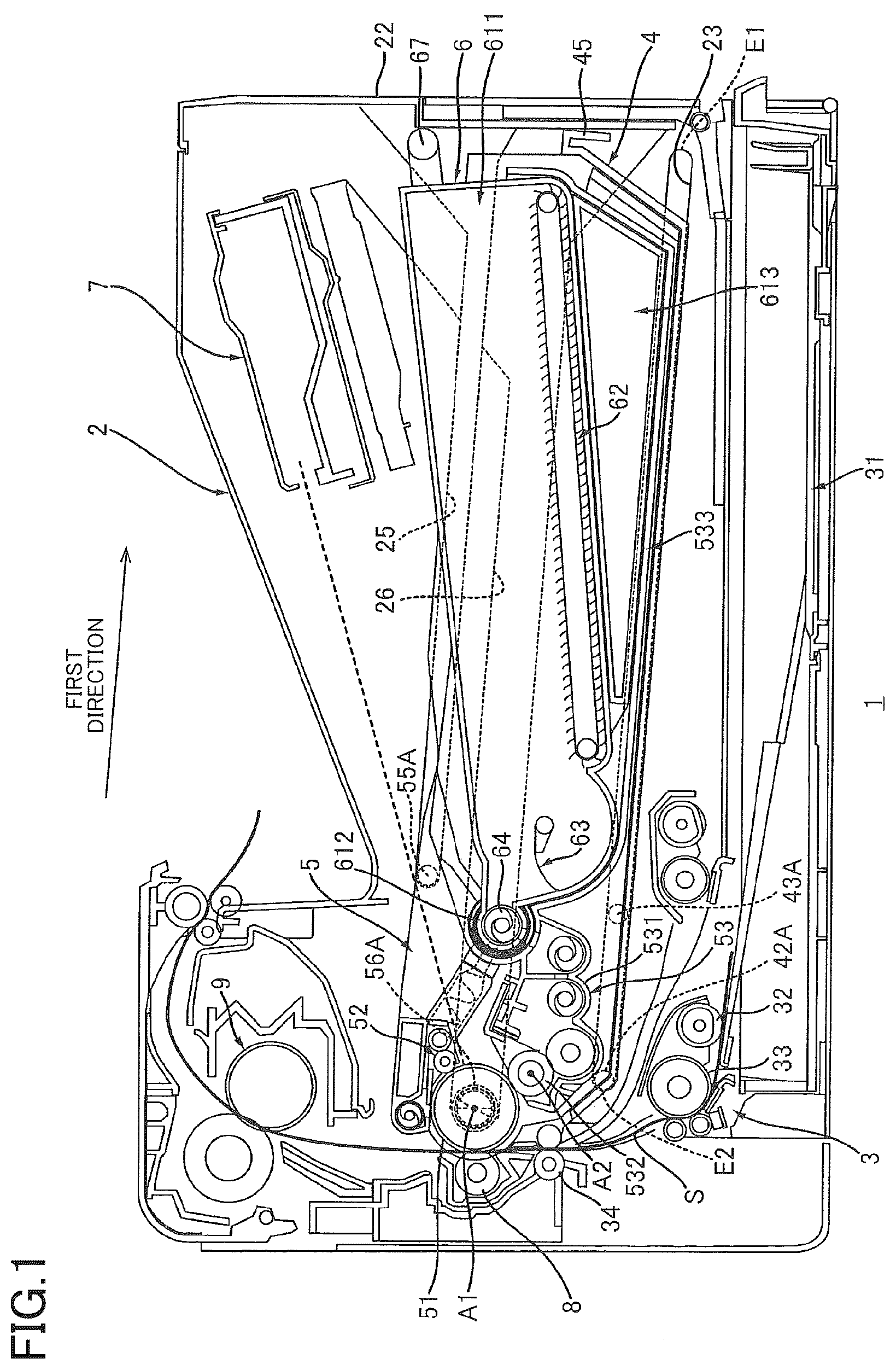
The objects, features, advantages, and technical and industrial significance of the present disclosure will be better understood by reading the following detailed description of embodiments, when considered in connection with the accompanying drawings, in which: is a cross-sectional view of an image forming device according to a first embodiment; illustrates the image forming device of in a state in which a drawer is located at an intermediate position and a toner cartridge is located at a cartridge first position; illustrates the image forming device of in a state in which the toner cartridge is detached from the drawer and the drawer is located at an outside position. A is an enlarged view of a stopper illustrated in , the view illustrating a state in which the stopper is located at a first position; B is an enlarged view of the stopper illustrated in A , the view illustrating a state in which the stopper is located at a second position; is a plan view of the drawer; is a cross-sectional view of the drawer of taken along line A-A in ; is a plan view of a drum cartridge; A is a cross-sectional view of the drum cartridge of taken along line B-B in , the view illustrating a state in which a shutter is located at a closing position; B illustrates a state in which the shutter of A is located at an open position; is a side view of the drum cartridge of ; is a plan view of the toner cartridge; A is a cross-sectional view of the toner cartridge of taken along line C-C in , the view illustrating a state in which a shutter is located at a closing position; B illustrates a state in which the shutter of A is located at an open position; is a side view of the toner cartridge of ; is a cross-sectional view of the toner cartridge of taken along line D-D in , the view illustrating the state in which the shutter is located at the open position; A is an explanatory view of a stopper according to a second embodiment, the view illustrating a state in which a cam is located at a cam first position and a stopper is located at a first position; B illustrates a state in which the cam of A is located at a cam second position and the stopper is located at a second position; is a side view of a toner cartridge according to the second embodiment; A is a cross-sectional view of the toner cartridge according to the second embodiment, the view illustrating a state in which a handle is located at a handle first position and the shutter is located at the closing position; B illustrates a state in which the handle of A is located at a handle second position and the shutter is located at the open position; illustrates an image forming device according to the second embodiment in a state in which the drawer is located at the intermediate position and the handle is located at the handle first position; A is a cross-sectional view of a drum cartridge according to the second embodiment, the view illustrating a state in which the shutter is located at the closing position; B illustrates a state in which the shutter of A is located at the open position; illustrates the image forming device of in a state in which the toner cartridge is detached from the drawer and the drawer is located at the outside position; A is an enlarged view of a locking lever of in a state in which the locking lever is located at a lock position; and B illustrates a state in which the locking lever of A is located at an unlock position.
DETAILED
DESCRIPTION OF THE EMBODIMENTS
1. Image Forming Device 1 Referring to , there will be explained an image forming device 1 according to a first embodiment. As shown in , the image forming device 1 includes a housing 2 , a sheet supplier 3 , a drawer 4 , a drum cartridge 5 , a toner cartridge 6 , an exposure device 7 , a transfer roller 8 , and a fixing device 9 . The image forming device 1 is for monochrome printing. Thus, the image forming device 1 includes one drum cartridge 5 and one toner cartridge 6 . 1.1 Housing 2 The housing 2 houses the sheet supplier 3 , the drawer 4 , the drum cartridge 5 , the toner cartridge 6 , the exposure device 7 , the transfer roller 8 , and the fixing device 9 . As shown in , the housing 2 has an opening 21 . The housing 2 includes a cover 22 . The cover 22 is movable between a closed position ( ) and an open position ( ). In a state in which the cover 22 is located at the closed position, the cover 22 closes the opening 21 . In a state in which the cover 22 is located at the open position, the cover opens the opening 21 . 1.2 Sheet Supplier 3 As shown in , the sheet supplier 3 is capable of supplying sheets S to a photoconductive drum 51 . The photoconductive drum 51 will be later explained. The sheet supplier 3 includes a sheet cassette 31 , a pickup roller 32 , a conveyance roller 33 , and a conveyance roller 34 . The sheet cassette 31 is capable of storing the sheets S. The pickup roller 32 picks up an uppermost one of the sheets S stacked on the sheet cassette 31 and coveys the picked-up sheet S toward the conveyance roller 33 . The conveyance roller 33 conveys the sheet S conveyed from the pickup roller 32 toward the conveyance roller 34 . The conveyance roller 34 conveys the sheet S conveyed from the conveyance roller 33 toward the photoconductive drum 51 . 1.3 Drawer 4 As shown in , in the state in which the cover 22 is located at the open position, the drawer 4 is movable in a first direction from an inside position ( ) to an outside position ( ) via an intermediate position ( ) through the opening 21 . The first direction intersects an up-down direction. The drum cartridge 5 and the toner cartridge 6 can be placed on the drawer 4 . The drawer 4 is movable in a state in which the drum cartridge 5 and the toner cartridge 6 are placed thereon. As shown in , the housing 2 includes a drawer guide 23 configured to guide the drawer 4 . The drawer guide 23 extends in the first direction. The drawer guide 23 is a groove. The drawer guide 23 may be a rib. The drawer guide 23 has a first end portion E 1 and a second end portion E 2 . The second end portion E 2 is located apart from the first end portion E 1 in the first direction and is located between the first end portion E 1 and the transfer roller 8 in the first direction. The drawer guide 23 inclines downward in a direction directed from the second end portion E 2 toward the first end portion E 1 . Owing to the thus inclined drawer guide 23 , the drawer 4 inclines downward in a direction directed from the inside position toward the outside position. This configuration enables the drawer 4 to be easily moved from the inside position to the outside position utilizing the weight of the drawer 4 . As shown in , the inside position is a position at which a guided portion 42 A of the drawer 4 engages the second end portion E 2 of the drawer guide 23 . The guided portion 42 A will be later explained. In the state in which the drawer 4 is located at the inside position, the entirety of the drawer 4 is disposed in the housing 2 . As shown in , the intermediate position is a position at which a guided portion 43 A of the drawer 4 contacts a stopper 24 and the drawer 4 stays between the inside position and the outside position. The stopper 24 and the guided portion 43 A will be later explained. As shown in , the outside position is a position at which the guided portion 43 A of the drawer 4 engages the first end portion E 1 of the drawer guide 23 . In the state in which the drawer 4 is located at the outside position, at least a part of the drawer 4 is disposed outside the housing 2 . 1.4 Drum Cartridge 5 The drum cartridge 5 mounted on the drawer 4 is detachable from the drawer 4 in the state in which the drawer 4 is located at the outside position. The state in which the drum cartridge 5 is mounted on the drawer 4 refers to a state in which the drum cartridge 5 is placed at a specific position on the drawer 4 . The drum cartridge 5 need not be fixed to the drawer 4 in the state in which the drum cartridge 5 is mounted on the drawer 4 . It is noted that the drum cartridge 5 is mountable on the drawer 4 in the state in which the drawer 4 is located at the outside position. As shown in , the drum cartridge 5 mounted on the drawer 4 cannot be detached from the drawer 4 in the state in which the drawer 4 is located at the inside position or the intermediate position. The drum cartridge 5 cannot be mounted on the drawer 4 in the state in which the drawer 4 is located at the inside position or the intermediate position. As shown in , the drum cartridge 5 includes the photoconductive drum 51 , a charging roller 52 , and a developer device 53 . 1.4.1 Photoconductive Drum 51 The photoconductive drum 51 is rotatable about an axis A 1 extending in a second direction that intersects the first direction and the up-down direction. Preferably, the second direction is orthogonal to the first direction and the up-down direction. The photoconductive drum 51 extends in the second direction and has a cylindrical shape. 1.4.2 Charging Roller 52 The charging roller 52 causes the surface of the photoconductive drum 51 to be charged. The charging roller 52 is in contact with the surface of the photoconductive drum 51 . The drum cartridge 5 may include a scorotron charging device in place of the charging roller 52 . 1.4.3 Developer Device 53 The developer device 53 is capable of supplying the toner to the photoconductive drum 51 . Specifically, the developer device 53 includes a developer housing 531 and a developer roller 532 . In other words, the drum cartridge 5 includes the developer housing 531 and the developer roller 532 . The developer housing 531 stores the toner to be supplied to the photoconductive drum 51 . The developer housing 531 supports the developer roller 532 . The developer roller 532 is rotatable about an axis A 2 extending in the second direction. The developer roller 532 is in contact with the photoconductive drum 51 . The developer roller 532 is capable of supplying the toner in the developer housing 531 to the photoconductive drum 51 . 1.5 Toner Cartridge 6 The toner cartridge 6 stores the toner to be supplied to the developer device 53 . As shown in , the toner cartridge 6 mounted on the drawer 4 is detachable from the drawer 4 in the state in which the drawer 4 is located at the intermediate position. The state in which the toner cartridge 6 is mounted on the drawer 4 refers to a state in which the toner cartridge 6 is placed at a specific position on the drawer 4 . The toner cartridge 6 need not be fixed to the drawer 4 in the state in which the toner cartridge 6 is mounted on the drawer 4 . The toner cartridge 6 may be mounted on the drawer 4 via the drum cartridge 5 . In the first embodiment, the toner cartridge 6 can be mounted on the drum cartridge 5 mounted on the drawer 4 . The toner cartridge 6 can be mounted on the drawer 4 in the state in which the drawer 4 is located at the intermediate position. The toner cartridge 6 and the photoconductive drum 51 are arranged in the first direction in a state in which the drum cartridge 5 and the toner cartridge 6 are mounted on the drawer 4 . Specifically, in the state in which the drum cartridge 5 and the toner cartridge 6 are mounted on the drawer 4 , the toner cartridge 6 is located opposite to the transfer roller 8 with respect to the photoconductive drum 51 in the first direction, in other words, the photoconductive drum 51 is located between the transfer roller 8 and the toner cartridge 6 in the first direction. As shown in , the toner cartridge 6 cannot be mounted on the drawer 4 in the state in which the drawer 4 is located at the inside position. The toner cartridge 6 mounted on the drawer 4 cannot be detached from the drawer 4 in the state in which the drawer 4 is located at the inside position. 1.6 Exposure Device 7 As shown in , the exposure device 7 is capable of exposing the surface of the photoconductive drum 51 in the state in which the drum cartridge 5 and the toner cartridge 6 are mounted on the drawer 4 and the drawer 4 is located at the inside position. Specifically, the exposure device 7 is a laser scanning unit. The exposure device 7 exposes the surface of the photoconductive drum 51 in the state in which the surface of the photoconductive drum 51 is charged by the charging roller 52 , so that a latent image is formed on the surface of the photoconductive drum 51 . The developer device 53 supplies the toner onto the surface of the photoconductive drum 51 in the state in which the latent image is formed on the surface of the photoconductive drum 51 , so that a toner image is formed on the surface of the photoconductive drum 51 . 1.7 Transfer Roller 8 In the state in which the drawer 4 , on which the drum cartridge 5 is mounted, is located at the inside position, the transfer roller 8 is in contact with the photoconductive drum 51 . The sheet S conveyed by the conveyance roller 34 passes between the transfer roller 8 and the photoconductive drum 51 . In this instance, the transfer roller 8 transfers the toner image formed on the surface of the photoconductive drum 51 onto the sheet S. 1.8 Fixing Device 9 The fixing device 9 heats and pressurizes the sheet S onto which the toner image has been transferred, so as to fix the toner image on the sheet S. The sheet S that has passed through the fixing device 9 is discharged onto an upper surface of the housing 2 . 2. Details of Housing 2 Referring next to B , the housing 2 will be explained. As shown in , the housing 2 includes the stopper 24 , a guide 25 (as one example of a first guide), and a guide 26 (as one example of a second guide), in addition to the cover 22 and the drawer guide 23 described above. In other words, the image forming device 1 includes the stopper 24 , the guide 25 , and the guide 26 . 2.1 Stopper 24 The stopper 24 stops the drawer 4 that moves from the inside position toward the outside position, such that the drawer 4 stays at the intermediate position. The position, the shape, and the structure of the stopper 24 are not limited to any particular ones as long as the stopper 24 enables the drawer 4 that moves from the inside position toward the outside position to stay at the intermediate position. In the first embodiment, the stopper 24 is disposed in the housing 2 and is attached to the drawer guide 23 . As shown in A and 4 B , the stopper 24 is movable between a first position ( A ) and a second position ( B ). The stopper 24 includes a plate spring 241 . The stopper 24 is movable from the first position to the second position against a force of the plate spring 241 and is movable from the second position to the first position by the force of the plate spring 241 . When the drawer 4 moves from the inside position to the outside position in the state in which the stopper 24 is located at the first position, the stopper 24 comes into contact with the guided portion 43 A of the drawer 4 in the first direction, as shown in A , whereby the drawer 4 stops and stays at the intermediate position, as shown in . In other words, the stopper 24 located at the first position contacts, in the first direction, the guided portion 43 A of the drawer 4 located at the intermediate position, whereby the stopper 24 stops the drawer 4 from moving from the intermediate position to the outside position. When the drawer 4 , which is kept stayed at the intermediate position by the stopper 24 , is pulled toward the outside position, the stopper 24 is pushed by the guided portion 43 A as shown in B , so that the stopper 24 moves from the first position to the second position against the force of the plate spring 241 . In the state in which the stopper 24 is located at the second position, the stopper 24 is not in contact with the guided portion 43 A of the drawer 4 in the first direction. Thus, the drawer 4 does not stop and stay at the intermediate position and moves from the intermediate position ( ) to the outside position ( ). In other words, the stopper 24 allows the drawer 4 to move from the intermediate position to the outside position when the stopper 24 is located at the second position. 2.2 Guide 25 As shown in , the guide 25 is disposed in the housing 2 . The guide 25 is a groove extending in the first direction. As shown in , in the state in which the drum cartridge 5 is mounted on the drawer 4 and the drawer 4 is located at the inside position or the intermediate position, a guided portion 55 A (as one example of a first guided portion) of the drum cartridge 5 engages the guide 25 . The guided portion 55 A will be later explained. When the drawer 4 , on which the drum cartridge 5 is installed, moves between the inside position and the outside position, the guide 25 guides the guided portion 55 A. Thus, the guide 25 guides the drum cartridge 5 in the first direction when the drawer 4 , on which the drum cartridge 5 is mounted, moves between the inside position and the outside position. 2.3 Guide 26 As shown in , the guide 26 is disposed in the housing 2 so as to be apart from the guide 25 . The guide 26 is located at a height level lower than the guide 25 . The guide 26 is a groove extending in the first direction. As shown in , in the state in which the drum cartridge 5 is mounted on the drawer 4 and the drawer 4 is located at the inside position or the intermediate position, a guided portion 56 A (as one example of a second guided portion) of the drum cartridge 5 engages the guide 26 . The guided portion 56 A will be later explained. When the drawer 4 , on which the drum cartridge 5 is mounted, moves between the inside position and the outside position, the guide 26 guides the guided portion 56 A. Thus, the guide 26 guides the drum cartridge 5 in the first direction, together with the guide 25 when the drawer 4 , on which the drum cartridge 5 is mounted, moves between the inside position and the outside position. 3. Details of Drawer 4 Referring next to , the drawer 4 will be explained. As shown in , the drawer 4 is shaped like a tray. The drawer 4 extends in the first direction and the second direction. The drawer 4 includes a drawer side plate 41 A, a drawer side plate 41 B, the guided portion 42 A, a guided portion 42 B, the guided portion 43 A, a guided portion 43 B, a bottom plate 44 , and a drawer grip 45 . 3.1 Drawer Side Plate 41 A The drawer side plate 41 A is located at a first end portion of the drawer 4 in the second direction. The drawer 4 includes the first end portion and a second end portion in the second direction. The second end portion is apart from the first end portion in the second direction. The drawer side plate 41 A extends in the first direction. The drawer side plate 41 A has a first end portion E 11 and a second end portion E 12 in the first direction. The second end portion E 12 is apart from the first end portion E 11 in the first direction. The drawer side plate 41 A has a first surface S 1 and a second surface S 2 in the second direction. The second surface S 2 is located between the first surface S 1 and the drawer side plate 41 B in the second direction. As shown in , the drawer side plate 41 A includes a guide 46 A and a receiving portion 47 A. 3.1.1 Guide 46 A As shown in , the guide 46 A is provided at an edge of the drawer side plate 41 A. The guide 46 A may be provided on the second surface S 2 of the drawer side plate 41 A. The guide 46 A extends in the first direction and inclines with respect to the first direction. The guide 46 A gets closer to the bottom plate 44 as the guide 46 A gets closer to the second end portion E 12 . The guide 46 A includes a first end portion 461 and a second end portion 462 . The first end portion 461 is located between the first end portion E 11 of the drawer side plate 41 A and the second end portion E 12 of the drawer side plate 41 A in the first direction. The second end portion 462 is located between the first end portion 461 and the second end portion E 12 of the drawer side plate 41 A in the first direction. The guide 46 A guides the guided portion 56 A ( ) of the drum cartridge 5 in mounting the drum cartridge 5 on the drawer 4 . 3.1.2 Receiving Portion 47 A The receiving portion 47 A is located between the guide 46 A and the second end portion E 12 of the drawer side plate 41 A in the first direction. In the state in which the drum cartridge 5 is mounted on the drawer 4 ( ), the receiving portion 47 A receives the guided portion 56 A ( ) of the drum cartridge 5 . 3.2 Drawer Side Plate 41 B As shown in , the drawer side plate 41 B is located at the second end portion of the drawer 4 in the second direction. The drawer side plate 41 B is apart from the drawer side plate 41 A in the second direction. The drawer side plate 41 B includes a guide 46 B and a receiving portion 47 B. The above explanation of the drawer side plate 41 A is true of the drawer side plate 41 B. 3.3 Guided Portion 42 A The guided portion 42 A is located opposite to the drawer side plate 41 B with respect to the drawer side plate 41 A in the second direction. The guided portion 42 A is located on the first surface S 1 of the drawer side plate 41 A. The guided portion 42 A is a protrusion extending from the first surface S 1 of the drawer side plate 41 A. The guided portion 42 A may be attached to the first surface S 1 of the drawer side plate 41 A. The guided portion 42 A has a cylindrical shape. The guided portion 42 A engages the drawer guide 23 ( ) of the housing 2 so as to be guided by the drawer guide 23 . 3.4 Guided Portion 42 B The guided portion 42 B is located opposite to the drawer side plate 41 A with respect to the drawer side plate 41 B in the second direction. The above explanation of the guided portion 42 A is true of the guided portion 42 B. 3.5 Guided Portion 43 A The guided portion 43 A is apart from the guided portion 42 A in the first direction. The guided portion 43 A is located opposite to the drawer side plate 41 B with respect to the drawer side plate 41 A in the second direction. The guided portion 43 A is located on the first surface S 1 of the drawer side plate 41 A. The guided portion 43 A is a protrusion extending from the first surface S 1 of the drawer side plate 41 A. The guided portion 43 A may be attached to the first surface S 1 of the drawer side plate 41 A. The guided portion 43 A has a cylindrical shape. The guided portion 43 A engages the drawer guide 23 ( ) of the housing 2 so as to be guided by the drawer guide 23 . 3.6 Guided Portion 43 B The guided portion 43 B is located opposite to the drawer side plate 41 A with respect to the drawer side plate 41 B in the second direction. The above explanation of the guided portion 43 A is true of the guided portion 43 B. 3.7 Bottom Plate 44 The bottom plate 44 is located between the drawer side plate 41 A and the drawer side plate 41 B in the second direction so as to extend in the second direction. The bottom plate 44 is connected to the drawer side plate 41 A and the drawer side plate 41 B. 3.8 Drawer Grip 45 The drawer grip 45 is configured to be gripped by a user when the user moves the drawer 4 between the inside position and the outside position. The drawer grip 45 is located at an end of the drawer 4 in the first direction. The drawer grip 45 extends in the second direction. The drawer grip 45 includes a first end portion and a second end portion in the second direction. The first end portion of the drawer grip 45 is connected to the first end portion E 11 of the drawer side plate 41 A, and the second end portion of the drawer grip 45 is connected to the first end portion E 11 of the drawer side plate 41 B. 4. Details of Drum Cartridge 5 Referring next to , the drum cartridge 5 will be explained. As shown in , the drum cartridge 5 extends in the second direction. The drum cartridge 5 includes a drum cartridge side plate 54 A, a drum cartridge side plate 54 B, the guided portion 55 A, a guided portion 55 B, the guided portion 56 A, a guided portion 56 B, a drum cleaner 57 , a waste-toner conveyor pipe 58 , and a seal 59 , in addition to the photoconductive drum 51 , the charging roller 52 ( A ), and the developer device 53 described above. 4.1 Details of Developer Device 53 As shown in , the developer device 53 is located between the drum cartridge side plate 54 A and the drum cartridge side plate 54 B in the second direction. As shown in A , the developer device 53 includes a tray 533 , a connection portion 534 , and a shutter 535 shown in A (as one example of a second shutter), in addition to the developer housing 531 and the developer roller 532 described above. In other words, the drum cartridge 5 includes the connection portion 534 and the shutter 535 . 4.1.1 Tray 533 In the state in which the toner cartridge 6 is mounted on the drawer 4 ( ), the tray 533 supports the toner cartridge 6 . As shown in , the tray 533 includes a tray side plate 5331 A, a tray side plate 5331 B, a bottom plate 5332 , a protrusion 5333 A, a protrusion 5333 B, a protrusion 5334 A, and a protrusion 5334 B. 4.1.1.1 Tray Side Plate 5331 A The tray side plate 5331 A is located at a first end portion of the tray 533 in the second direction. The tray 533 includes the first end portion and a second end portion in the second direction. The first end portion is apart from the second end portion. The tray side plate 5331 A is located between the drum cartridge side plate 54 A and the tray side plate 5331 B in the second direction. The tray side plate 5331 A extends in a direction intersecting the axis A 1 , preferably, in a direction orthogonal to the axis A 1 . The tray side plate 5331 A includes a first surface S 11 and a second surface S 12 in the second direction. The second surface S 12 is located between the first surface S 11 and the tray side plate 5331 B in the second direction. As shown in A , the tray side plate 5331 A has a guide 5335 A (as one example of a third guide) and a groove 5336 A. In other words, the drum cartridge 5 has the guide 5335 A. The guide 5335 A is provided on the second surface S 12 of the tray side plate 5331 A. The guide 5335 A is located opposite to the photoconductive drum 51 with respect to the connection portion 534 in the first direction. In mounting the toner cartridge 6 on the drawer 4 in the state in which the drum cartridge 5 is mounted on the drawer 4 , a guided portion 66 A ( ) of the toner cartridge 6 engages the guide 5335 A. The guided portion 66 A will be later explained. In mounting the toner cartridge 6 on the drawer 4 in the state in which the drum cartridge 5 is mounted on the drawer 4 , the guide 5335 A guides the guided portion 66 A toward the connection portion 534 . Thus, the guide 5335 A guides a toner supply portion 612 ( ) of the toner cartridge 6 toward the connection portion 534 in mounting the toner cartridge 6 on the drawer 4 in the state in which the drum cartridge 5 is mounted on the drawer 4 . The toner supply portion 612 will be later explained. The guide 5335 A extends in a third direction that intersects the first direction and the second direction. Preferably, the third direction intersects the first direction and is orthogonal to the second direction. Specifically, the third direction is a direction directed downward toward the housing 2 in the state in which the drum cartridge 5 is mounted on the drawer 4 and the drawer 4 is located at the outside position ( ). The guide 5335 A is a groove. The groove 5336 A is located between the guide 5335 A and the connection portion 534 in the third direction. The groove 5336 A is apart from the guide 5335 A in the third direction and extends in the third direction. In the state in which the drum cartridge 5 and the toner cartridge 6 are mounted on the drawer 4 , the guided portion 66 A ( ) of the toner cartridge 6 engages the groove 5336 A. 4.1.1.2 Tray Side Plate 5331 B As shown in , the tray side plate 5331 B is apart from the tray side plate 5331 A in the second direction. The tray side plate 5331 B is located at the second end portion of the tray 533 in the second direction. The above explanation of the tray side plate 5331 A is true of the tray side plate 5331 B. 4.1.1.3 Bottom Plate 5332 The bottom plate 5332 is located between the tray side plate 5331 A and the tray side plate 5331 B in the second direction. The bottom plate 5332 extends in the second direction. The bottom plate 5332 is connected to the tray side plate 5331 A and the tray side plate 5331 B. 4.1.1.4 Protrusion 5333 A The protrusion 5333 A is located opposite to the protrusion 5333 B with respect to the developer housing 531 in the second direction. The protrusion 5333 A is located on an outer surface of the developer housing 531 in the second direction. The protrusion 5333 A extends in the second direction. The protrusion 5333 A extends along the axis A 2 . The protrusion 5333 A has a cylindrical shape. The protrusion 5333 A may be attached to an end of a shaft of the developer roller 532 . 4.1.1.5 Protrusion 5333 B The protrusion 5333 B is located opposite to the protrusion 5333 A with respect to the developer housing 531 in the second direction. The explanation of the protrusion 5333 A is true of the protrusion 5333 B. 4.1.1.6 Protrusion 5334 A The protrusion 5334 A is apart from the protrusion 5333 A in the first direction. The protrusion 5334 A is located opposite to the tray side plate 5331 B with respect to the tray side plate 5331 A in the second direction. The protrusion 5334 A is located on the first surface S 11 of the tray side plate 5331 A. The protrusion 5334 A extends from the first surface S 11 of the tray side plate 5331 A. The protrusion 5334 A may be attached to the first surface S 11 of the tray side plate 5331 A. The protrusion 5334 A extends in the second direction. The protrusion 5334 A has a cylindrical shape. 4.1.1.7 Protrusion 5334 B The protrusion 5334 B is located opposite to the tray side plate 5331 A with respect to the tray side plate 5331 B in the second direction. The above explanation of the protrusion 5334 A is true of the protrusion 5334 B. 4.1.2 Connection Portion 534 As shown in A , the connection portion 534 is located on the developer housing 531 in the state in which the drum cartridge 5 is mounted on the drawer 4 . In the state in which the drum cartridge 5 and the toner cartridge 6 are mounted on the drawer 4 , the connection portion 534 is connected to the toner supply portion 612 ( A ) and a waste-toner inlet portion 614 ( ) of the toner cartridge 6 . The connection portion 534 is located between the guide 5335 A and the developer housing 531 . The connection portion 534 is located between the guided portion 55 A and the photoconductive drum 51 in the first direction. As shown in , the connection portion 534 is located between the tray side plate 5331 A and the tray side plate 5331 B in the second direction. The connection portion 534 extends in the second direction. The connection portion 534 includes a first end portion and a second end portion in the second direction. The second end portion is located apart from the first end portion in the second direction. The first end portion of the connection portion 534 in the second direction is connected to the tray side plate 5331 A, and the second end portion of the connection portion 534 in the second direction is connected to the tray side plate 5331 B. The connection portion 534 has a semi-cylindrical shape. The connection portion 534 has a waste-toner discharge opening 5341 and an inlet opening 5342 . In other words, the drum cartridge 5 has the waste-toner discharge opening 5341 and the inlet opening 5342 . The waste-toner discharge opening 5341 is located at the first end portion of the connection portion 534 in the second direction. The toner conveyed by the waste-toner conveyor pipe 58 can be discharged through the waste-toner discharge opening 5341 . The waste-toner discharge opening 5341 communicates with an inner space of the waste-toner conveyor pipe 58 . The inlet opening 5342 is located at the second end portion of the connection portion 534 in the second direction. In the state in which the drum cartridge 5 and the toner cartridge 6 are mounted on the drawer 4 , the toner discharged from a discharge opening 617 ( B ) of the toner cartridge 6 can be received by the inlet opening 5342 . The discharge opening 617 will be later explained. As shown in A , the inlet opening 5342 communicates with an inner space of the developer housing 531 . 4.1.3 Shutter 535 As shown in A and 8 B , the shutter 535 is movable between a closing position ( A ) and an open position ( B ) with respect to the inlet opening 5342 and the waste-toner discharge opening 5341 . The shutter 535 is rotatable between the closing position and the open position about an axis A 3 . As shown in A , when the shutter 535 is located at the closing position, the shutter 535 closes the inlet opening 5342 and the waste-toner discharge opening 5341 . On the other hand, when the shutter 535 is located at the open position as shown in B , the shutter 535 opens the inlet opening 5342 and the waste-toner discharge opening 5341 . As shown in 8 A, the shutter 535 includes a shutter end plate 5351 A, a shutter end plate 5351 B, and a shutter body 5352 . The shutter end plate 5351 B is not illustrated. 4.1.3.1 Shutter End Plate 5351 A The shutter end plate 5351 A is located at a first end portion of the shutter 535 in the second direction. The shutter 535 extends in the second direction. The shutter 535 includes the first end portion and a second end portion in the second direction. The second end portion is apart from the first end portion in the second direction. The shutter end plate 5351 A is located on the second surface S 12 of the tray side plate 5331 A of the tray 533 . The shutter end plate 5351 A is a circular plate and has a groove 5353 A and a groove 5354 A. The groove 5353 A extends in a radial direction of the shutter end plate 5351 A. In a state in which the shutter 535 is located at the closing position, the groove 5353 A is located between the guide 5335 A and the groove 5336 A and extends in the third direction. In the state in which the shutter 535 is located at the closing position, the groove 5353 A is connected to the guide 5335 A and the groove 5336 A. As shown in B , the groove 5353 A extends in a direction different from the third direction in a state in which the shutter 535 is located at the open position. As shown in A , the groove 5354 A extends in the radial direction of the shutter end plate 5351 A. The groove 5354 A is apart from the groove 5353 A in the radial direction of the shutter end plate 5351 A. In the state in which the shutter 535 is located at the closing position, the groove 5354 A is located opposite to the groove 5353 A with respect to the groove 5336 A. In the state in which the shutter 535 is located at the closing position, the groove 5354 A extends in the third direction and is connected to the groove 5336 A. As shown in B , the groove 5354 A extends in a direction different from the third direction in the state in which the shutter 535 is located at the open position. 4.1.3.2 Shutter End Plate 5351 B The shutter end plate 5351 B is apart from the shutter end plate 5351 A in the second direction. The shutter end plate 5351 B is located at the second end portion of the shutter 535 in the second direction. The above explanation of the shutter end plate 5351 A is true of the shutter end plate 5351 B. 4.1.3.3 Shutter Body 5352 In the state in which the shutter 535 is located at the closing position, the shutter body 5352 closes the waste-toner discharge opening 5341 and the inlet opening 5342 . The shutter body 5352 is located between the shutter end plate 5351 A and the shutter end plate 5351 B in the second direction. The shutter body 5352 extends in the second direction. The shutter body 5352 includes a first end portion and a second end portion in the second direction. The second end portion is apart from the first end portion in the second direction. The first end portion of the shutter body 5352 in the second direction is connected to the shutter end plate 5351 A, and the second end portion of the shutter body 5352 in the second direction is connected to the shutter end plate 5351 B. 4.2 Drum Cartridge Side Plate 54 A As shown in , the drum cartridge side plate 54 A is located at the first end portion of the drum cartridge 5 in the second direction. The drum cartridge 5 includes the first end portion and a second end portion in the second direction. The second end portion is apart from the first end portion in the second direction. The drum cartridge side plate 54 A extends in a direction intersecting the axis A 1 , preferably, in a direction orthogonal to the axis A 1 . The drum cartridge side plate 54 A has a first surface S 21 and a second surface S 22 in the second direction. The second surface S 22 is located between the first surface S 21 and the drum cartridge side plate 54 B in the second direction. The drum cartridge side plate 54 A has an aperture 541 A, an aperture 542 A ( ), and an aperture 543 A ( ). 4.2.1 Aperture 541 A The aperture 541 A is a through-hole. One end of the photoconductive drum 51 engages the aperture 541 A. Specifically, the photoconductive drum 51 includes a drum body 511 , a flange 512 A, and a flange 512 B. The drum body 511 extends in the second direction and has a cylindrical shape. The drum body 511 includes a first end portion in the second direction and a second end portion that is apart from the first end portion in the second direction. The flange 512 A is located at the first end portion of the drum body 511 . The flange 512 A is attached to the first end portion of the drum body 511 so as to extend in the second direction. The flange 512 A has a cylindrical shape. The flange 512 B is located at the second end portion of the drum body 511 . The flange 512 B is attached to the second end portion of the drum body 511 . The flange 512 B extends in the second direction. The flange 512 B has a cylindrical shape. The flange 512 A engages the aperture 541 A. 4.2.2 Aperture 542 A As shown in , the aperture 542 A is an elongate aperture and extends in a direction directed from the axis A 2 toward the axis A 1 . The protrusion 5333 A engages the aperture 542 A. The aperture 542 A guides the protrusion 5333 A in the direction directed from the axis A 2 toward the axis A 1 . 4.2.3 Aperture 543 A The aperture 543 A is an elongate aperture and extends in the first direction. The protrusion 5334 A engages the aperture 543 A. The protrusion 5333 A engages the aperture 542 A, and the protrusion 5334 A engages the aperture 543 A, so that the developer device 53 is supported by the drum cartridge side plate 54 A. 4.3 Drum Cartridge Side Plate 54 B As shown in , the drum cartridge side plate 54 B is apart from the drum cartridge side plate 54 A in the second direction. The drum cartridge side plate 54 B is located at the second end portion of the drawer 4 in the second direction. The above explanation of the drum cartridge side plate 54 A is true of the drum cartridge side plate 54 B (i.e. the drum cartridge side plate 54 B includes the aperture 541 B, the guide 5335 B, etc.). 4.4 Guided Portion 55 A The guided portion 55 A is located opposite to the drum cartridge side plate 54 B with respect to the drum cartridge side plate 54 A in the second direction. The guided portion 55 A is located on the first surface S 21 of the drum cartridge side plate 54 A. The guided portion 55 A is a protrusion. The guided portion 55 A extends from the first surface S 21 of the drum cartridge side plate 54 A. The guided portion 55 A may be attached to the first surface S 21 of the drum cartridge side plate 54 A. The guided portion 55 A extends in the second direction and has a cylindrical columnar shape. As shown in , when the drawer 4 moves between the inside position and the outside position in the state in which the drum cartridge 5 is mounted on the drawer 4 , the guided portion 55 A is guided by the guide 25 of the housing 2 . As shown in , in the state in which the drawer 4 , on which the drum cartridge 5 is mounted, is located at the inside position or the intermediate position, the guided portion 55 A engages the guide 25 of the housing 2 . In this state, the guide 25 stops the guided portion 55 A from moving in a direction intersecting the first direction. Thus, the guide 25 stops the drum cartridge 5 from moving in the direction intersecting the first direction. As shown in , in the state in which the drawer 4 , on which the drum cartridge 5 is mounted, is located at the outside position, the guided portion 55 A is disengaged from the guide 25 of the housing 2 . 4.5 Guided Portion 55 B As shown in , the guided portion 55 B is located opposite to the drum cartridge side plate 54 A with respect to the drum cartridge side plate 54 B in the second direction. The above explanation of the guided portion 55 A is true of the guided portion 55 B. 4.6 Guided Portion 56 A The guided portion 56 A is located opposite to the guided portion 55 A with respect to the connection portion 534 in the first direction. The guided portion 56 A is located opposite to the drum cartridge side plate 54 B with respect to the drum cartridge side plate 54 A in the second direction. The guided portion 56 A is located on the first surface S 21 of the drum cartridge side plate 54 A. The guided portion 56 A is a protrusion. The guided portion 56 A extends from the first surface S 21 of the drum cartridge side plate 54 A. The guided portion 56 A may be attached to the first surface S 21 of the drum cartridge side plate 54 A. The guided portion 56 A extends in the second direction. The guided portion 56 A extends along the axis A 1 and has a cylindrical shape. In the first embodiment, one end of the photoconductive drum 51 in the second direction is fitted to the guided portion 56 A. The flange 512 A of the photoconductive drum 51 is fitted to the guided portion 56 A. The guided portion 56 A may be the one end of the photoconductive drum 51 in the second direction. The guided portion 56 A may be the flange 512 A of the photoconductive drum 51 . The one end of the photoconductive drum 51 in the second direction need not be necessarily fitted to the guided portion 56 A. In mounting the drum cartridge 5 on the drawer 4 , the guided portion 56 A is guided by the guide 46 A ( ) of the drawer 4 . In the state in which the drum cartridge 5 is mounted on the drawer 4 , the guided portion 56 A engages the receiving portion 47 A ( ) of the drawer 4 . As shown in , when the drawer 4 moves between the inside position and the outside position in the state in which the drum cartridge 5 is mounted on the drawer 4 , the guided portion 56 A is guided by the guide 26 of the housing 2 . As shown in , in the state in which the drawer 4 , on which the drum cartridge 5 is mounted, is located at the inside position or the intermediate position, the guided portion 56 A engages the guide 26 of the housing 2 . In this state, the guide 26 stops the guided portion 56 A from moving in the direction intersecting the first direction. Thus, the guide 26 cooperates with the guide 25 to stop the drum cartridge 5 from moving in the direction intersecting the first direction. As shown in , in the state in which the drawer 4 , on which the drum cartridge 5 is mounted, is located at the outside position, the guided portion 56 A is disengaged from the guide 26 of the housing 2 . 4.7 Guided Portion 56 B As shown in , the guided portion 56 B is located opposite to the drum cartridge side plate 54 A with respect to the drum cartridge side plate 54 B in the second direction. The above explanation of the guided portion 56 A is true of the guided portion 56 B. 4.8 Drum Cleaner 57 The drum cleaner 57 is located between the drum cartridge side plate 54 A and the drum cartridge side plate 54 B in the second direction. The drum cleaner 57 extends in the second direction. The drum cleaner 57 includes a first end portion in the second direction and a second end portion that is apart from the first end portion in the second direction. The first end portion of the drum cleaner 57 is connected to the drum cartridge side plate 54 A, and the second end portion of the drum cleaner 57 is connected to the drum cartridge side plate 54 B. The drum cleaner 57 collects waste toner that remains on the surface of the photoconductive drum 51 without being transferred to the sheet S. As shown in A , the drum cleaner 57 includes a cleaner housing 571 , a cleaning blade 572 , and an auger screw 573 . 4.8.1 Cleaner Housing 571 As shown in , the cleaner housing 571 is located between the drum cartridge side plate 54 A and the drum cartridge side plate 54 B in the second direction. The cleaner housing 571 extends in the second direction. The cleaner housing 571 includes a first end portion and a second end portion in the second direction. The first end portion of the cleaner housing 571 is connected to the drum cartridge side plate 54 A, and the second end portion of the cleaner housing 571 is connected to the drum cartridge side plate 54 B. As shown in A , the cleaner housing 571 has an opening 574 . 4.8.2 Cleaning Blade 572 The cleaning blade 572 is attached to the cleaner housing 571 . The cleaning blade 572 is in contact with the surface of the photoconductive drum 51 at its edge. When the photoconductive drum 51 rotates, the waste toner on the surface of the photoconductive drum 51 comes into contact with the edge of the cleaning blade 572 so as to be removed from the surface of the photoconductive drum 51 . The thus removed waste toner is stored in the cleaner housing 571 through the opening 574 . 4.8.3 Auger Screw 573 The auger screw 573 is disposed in the cleaner housing 571 . As shown in , the auger screw 573 extends in the second direction. The auger screw 573 conveys the waste toner in the cleaner housing 571 toward the waste-toner conveyor pipe 58 . 4.9 Waste-Toner Conveyor Pipe 58 The waste-toner conveyor pipe 58 conveys the waste toner from the drum cleaner 57 to the waste-toner discharge opening 5341 . Specifically, the waste-toner conveyor pipe 58 conveys the waste toner in the cleaner housing 571 to the waste-toner discharge opening 5341 . The waste-toner conveyor pipe 58 includes a pipe 581 and a screw 582 . The pipe 581 includes a first end portion and a second end portion that is apart from the first end portion. The first end portion of the pipe 581 is connected to the cleaner housing 571 of the drum cleaner 57 , and the second end portion of the pipe 581 is connected to the connection portion 534 . An inner space of the pipe 581 communicates with an inner space of the cleaner housing 571 and the waste-toner discharge opening 5341 . Thus, the waste toner in the cleaner housing 571 is discharged from the waste-toner discharge opening 5341 through the pipe 581 . The screw 582 is disposed in the pipe 581 . The screw 582 conveys the waste toner in the pipe 581 toward the waste-toner discharge opening 5341 . The screw 582 extends in a direction in which the pipe 581 extends. The screw 582 is connected to the auger screw 573 . The screw 582 is rotatable together with the auger screw 573 . Specifically, the screw 582 is a shaftless screw. 4.10 Seal 59 The seal 59 is provided between the waste-toner conveyor pipe 58 and the connection portion 534 . The seal 59 seals between the waste-toner conveyor pipe 58 and the connection portion 534 so as to surround the waste-toner discharge opening 5341 . This arrangement prevents leakage of the waste toner from between the waste-toner conveyor pipe 58 and the connection portion 534 . The seal 59 has elasticity. Specifically, the seal 59 is a sponge. 5. Details of Toner Cartridge 6 Referring next to , 2 , and 10 - 13 , the toner cartridge 6 will be explained. As shown in , the toner cartridge 6 extends in the second direction. The toner cartridge 6 includes a first end portion E 31 and a second end portion E 32 in the second direction. The second end portion E 32 is apart from the first end portion E 31 in the second direction. The toner cartridge 6 extends in the first direction. The toner cartridge 6 includes a first end portion E 41 and a second end portion E 42 in the first direction. The second end portion E 42 is apart from the first end portion E 41 in the first direction. As shown in , the toner cartridge 6 includes a toner cartridge housing 61 , a belt conveyor 62 ( ), an agitator 63 ( ), an auger screw 64 ( ), a shutter 65 (as one example of a first shutter), the guided portion 66 A, a guided portion 66 B, and a toner grip 67 . 5.1 Toner Cartridge Housing 61 The toner cartridge housing 61 includes a toner storage portion 611 , the toner supply portion 612 , a waste-toner storage portion 613 , a waste-toner inlet portion 614 , a protrusion 615 A, a protrusion 615 B, a protrusion 616 A, and a protrusion 616 B. In other words, the toner cartridge 6 includes the toner supply portion 612 . 5.1.1 Toner Storage Portion 611 The toner storage portion 611 stores the toner. 5.1.2 Toner Supply Portion 612 The toner supply portion 612 is located at the first end portion E 41 of the toner cartridge 6 in the first direction. In the state in which the drum cartridge 5 and the toner cartridge 6 are mounted on the drawer 4 , the toner supply portion 612 is capable of supplying the toner to the developer device 53 ( ) of the drum cartridge 5 . As shown in A , the toner supply portion 612 is connected to the toner storage portion 611 . An inner space of the toner supply portion 612 communicates with an inner space of the toner storage portion 611 . The inner space of the toner supply portion 612 does not communicate with an inner space of the waste-toner storage portion 613 ( ) and an inner space of the waste-toner inlet portion 614 ( ). As shown in , the toner supply portion 612 extends in the second direction and has a cylindrical shape. The toner supply portion 612 has the discharge opening 617 . The discharge opening 617 is located at the second end portion E 32 of the toner cartridge 6 in the second direction. The discharge opening 617 communicates with the inner space of the toner supply portion 612 . The toner in the toner supply portion 612 can be discharged through the discharge opening 617 . 5.1.3 Waste-Toner Storage Portion 613 As shown in , in the state in which the toner cartridge 6 and the drum cartridge 5 are mounted on the drawer 4 , the waste-toner storage portion 613 is located below the toner storage portion 611 . The waste-toner storage portion 613 stores the waste toner. The inner space of the waste-toner storage portion 613 does not communicate with the inner space of the toner storage portion 611 and the inner space of the toner supply portion 612 . 5.1.4 Waste-Toner Inlet Portion 614 As shown in , the waste-toner inlet portion 614 is located at the first end portion E 31 of the toner cartridge 6 in the second direction. As shown in , the waste-toner inlet portion 614 is shaped like a pipe. The waste-toner inlet portion 614 includes a first end portion and a second end portion in a direction of extension thereof. The first end portion of the waste-toner inlet portion 614 is located at the first end portion E 41 of the toner cartridge 6 in the first direction. The first end portion of the waste-toner inlet portion 614 is located between the guided portion 66 A and the toner supply portion 612 in the second direction. The second end portion of the waste-toner inlet portion 614 is connected to the waste-toner storage portion 613 . The inner space of the waste-toner inlet portion 614 communicates with the inner space of the waste-toner storage portion 613 . The inner space of the waste-toner inlet portion 614 does not communicate with the inner space of the toner storage portion 611 ( ) and the inner space of the toner supply portion 612 ( ). In the state in which the toner cartridge 6 and the drum cartridge 5 are mounted on the drawer 4 , the second end portion of the waste-toner inlet portion 614 is located at a height level lower than the first end portion of the waste-toner inlet portion 614 . As shown in , the waste-toner inlet portion 614 has a waste-toner inlet opening 618 . The waste-toner inlet opening 618 is located at the first end portion of the waste-toner inlet portion 614 . The waste-toner inlet opening 618 is located at the first end portion E 41 of the toner cartridge 6 in the first direction. The waste-toner inlet opening 618 is located between the guided portion 66 A and the toner supply portion 612 in the second direction. The waste-toner inlet opening 618 communicates with the inner space of the waste-toner inlet portion 614 . 5.1.5 Protrusion 615 A The protrusion 615 A is located at the first end portion E 31 of the toner cartridge 6 in the second direction. The protrusion 615 A extends from the waste-toner inlet portion 614 . The protrusion 615 A extends in the second direction and has a cylindrical columnar shape. In the state in which the drum cartridge 5 and the toner cartridge 6 are mounted on the drawer 4 , the protrusion 615 A engages the groove 5353 A ( A ) of the shutter 535 of the drum cartridge 5 . 5.1.6 Protrusion 615 B The protrusion 615 B is located at the second end portion E 32 of the toner cartridge 6 in the second direction. The protrusion 615 B extends from the toner supply portion 612 . The above explanation of the protrusion 615 A is true of the protrusion 615 B. 5.1.7 Protrusion 616 A The protrusion 616 A is located at the first end portion E 31 of the toner cartridge 6 in the second direction. The protrusion 616 A is apart from the protrusion 615 A. The protrusion 616 A is located opposite to the protrusion 615 A with respect to the guided portion 66 A. In the state in which the drum cartridge 5 and the toner cartridge 6 are mounted on the drawer 4 and the toner cartridge 6 is located at a cartridge first position ( ), the protrusion 615 A and the protrusion 616 A are arranged in the third direction. The cartridge first position will be later explained. In the state in which the drum cartridge 5 and the toner cartridge 6 are mounted on the drawer 4 and the toner cartridge 6 is located at a cartridge second position ( ), the protrusion 615 A and the protrusion 616 A are arranged in a direction different from the third direction. The cartridge second position will be later explained. The protrusion 616 A extends from the waste-toner inlet portion 614 . The protrusion 616 A extends in the second direction and has a columnar cylindrical shape. In the state in which the drum cartridge 5 and the toner cartridge 6 are mounted on the drawer 4 , the protrusion 616 A engages the groove 5354 A ( A ) of the shutter 535 of the drum cartridge 5 . 5.1.8 Protrusion 616 B The protrusion 616 B is located at the second end portion E 32 of the toner cartridge 6 in the second direction. The protrusion 616 B extends from the toner supply portion 612 . The above explanation of the protrusion 616 A is true of the protrusion 616 B. 5.2 Belt Conveyor 62 As shown in , the belt conveyor 62 is disposed in the toner storage portion 611 . The belt conveyor 62 conveys the toner in the toner storage portion 611 toward the agitator 63 . 5.3 Agitator 63 As shown in A , the agitator 63 is disposed in the toner storage portion 611 . The agitator 63 conveys the toner in the toner storage portion 611 to the toner supply portion 612 . The agitator 63 is rotatable about an axis A 4 . In the state in which the toner cartridge 6 and the drum cartridge 5 are mounted on the drawer 4 , the axis A 4 of the agitator 63 is located at a height level lower than the discharge opening 617 . 5.4 Auger Screw 64 The auger screw 64 is disposed in the toner supply portion 612 . As shown in , the auger screw 64 extends in the second direction. The auger screw 64 conveys the toner in the toner supply portion 612 toward the discharge opening 617 . 5.5 Shutter 65 As shown in A and 11 B , the shutter 65 is movable between a closing position ( A ) and an open position ( B ) with respect to the discharge opening 617 . The shutter 65 is rotatable about an axis A 5 between the closing position and the open position. As shown in A , the shutter 65 closes the discharge opening 617 in the state in which the shutter 65 is located at the closing position. The shutter 65 further closes the waste-toner inlet opening 618 in the state in which the shutter 65 is located at the closing position. As shown in B , the discharge opening 617 is open in the state in which the shutter 65 is located at the open position. Further, the waste-toner inlet opening 618 is open in the state in which the shutter 65 is located at the open position as shown in . As shown in , the shutter 65 extends in the second direction. The shutter 65 includes a first end portion in the second direction and a second end portion that is apart from the first end portion in the second direction. The shutter 65 includes a shutter end plate 651 A, a shutter end plate 651 B, and a shutter body 652 . 5.5.1 Shutter End Plate 651 A The shutter end plate 651 A is located at the first end portion of the shutter 65 in the second direction. The shutter end plate 651 A is located opposite to the toner supply portion 612 with respect to the first end portion of the waste-toner inlet portion 614 in the second direction. In other words, the first end portion of the waste-toner inlet portion 614 is located between the shutter end plate 651 A and the toner supply portion 612 in the second direction. As shown in , the shutter end plate 651 A is a circular plate and has a through-hole 6511 A and a through-hole 6512 A. The through-hole 6511 A extends in the circumferential direction of the shutter end plate 651 A. The protrusion 615 A passes through the through-hole 6511 A. The through-hole 6512 A is apart from the through-hole 6511 A. The through-hole 6512 A is located opposite to the through-hole 6511 A with respect to the guided portion 66 A and extends in the circumferential direction of the shutter end plate 651 A. The protrusion 616 A passes through the through-hole 6512 A. 5.5.2 Shutter End Plate 651 B As shown in , the shutter end plate 651 B is located at the second end portion of the shutter 65 in the second direction. The shutter end plate 651 B is apart from the shutter end plate 651 A in the second direction. The shutter end plate 651 B is located opposite to the shutter end plate 651 A with respect to the toner supply portion 612 in the second direction. In other words, the toner supply portion 612 is located between the shutter end plate 651 A and the shutter end plate 651 B. The above explanation of the shutter end plate 651 A is true of the shutter end plate 651 B. 5.5.3 Shutter Body 652 As shown in A , in the state in which the shutter 65 is located at the closing position, the shutter body 652 closes the discharge opening 617 and the waste-toner inlet opening 618 . As shown in , the shutter body 652 is located between the shutter end plate 651 A and the shutter end plate 651 B in the second direction. The shutter body 652 extends in the second direction. The shutter body 652 includes a first end portion in the second direction and a second end portion that is apart from the first end portion in the second direction. The first end portion of the shutter body 652 in the second direction is connected to the shutter end plate 651 A, and the second end portion of the shutter body 652 in the second direction is connected to the shutter end plate 651 B. 5.6 Guided Portion 66 A The guided portion 66 A is located at the first end portion E 31 of the toner cartridge 6 in the second direction. The guided portion 66 A is a protrusion. The guided portion 66 A extends from the shutter end plate 651 A of the shutter 65 . The guided portion 66 A may be attached to the shutter end plate 651 A of the shutter 65 . As shown in , the guided portion 66 A extends in the radial direction of the shutter end plate 651 A. The guided portion 66 A is a rib. When the toner cartridge 6 is mounted on the drawer 4 , the guided portion 66 A is guided by the guide 5335 A ( A ) of the drum cartridge 5 in the state in which the shutter 65 is located at the closing position. In the state in which the drum cartridge 5 and the toner cartridge 6 are mounted on the drawer 4 ( ), the guided portion 66 A engages the groove 5336 A ( A ) of the developer device 53 , whereby the shutter 65 becomes unrotatable with respect to the developer device 53 , in other words, the shutter 65 becomes unrotatable with respect to the connection portion 534 . In the state in which the guided portion 66 A is engaged in the groove 5336 A, the guided portion 66 A extends in the third direction. 5.7 Guided Portion 66 B As shown in , the guided portion 66 B is apart from the guided portion 66 A in the second direction. The guided portion 66 B is located at the second end portion E 32 of the toner cartridge 6 in the second direction. The guided portion 66 B extends from the shutter end plate 651 B of the shutter 65 . The guided portion 66 B may be attached to the shutter end plate 651 B of the shutter 65 . The above explanation of the guided portion 66 A is true of the guided portion 66 B. Thus, the guided portion 66 B is not explained here. 5.8 Toner Grip 67 The toner grip 67 is located at the second end portion E 42 of the toner cartridge 6 in the first direction. The toner grip 67 is located opposite to the toner supply portion 612 with respect to the toner storage portion 611 in the first direction. The toner grip 67 is configured to be gripped by the user. As shown in , in the state in which the toner cartridge 6 is mounted on the drawer 4 and the drawer 4 is located at the intermediate position, the toner grip 67 is located outside the housing 2 and above the drawer grip 45 . This configuration enables the toner grip 67 and the drawer grip 45 to be easily gripped in the state in which the drawer 4 is located at the intermediate position, so that the toner cartridge 6 can be smoothly detached from the drawer 4 in the state in which the drum cartridge 5 is mounted on the drawer 4 . 5.9 Opening and Closing of Shutter 65 and Shutter 535 As shown in , in the state in which the drum cartridge 5 and the toner cartridge 6 are mounted on the drawer 4 and the drawer 4 is located at the intermediate position, the toner cartridge 6 is pivotable about the toner supply portion 612 between the cartridge first position ( ) and the cartridge second position ( ). The user can pivot the toner cartridge 6 between the cartridge first position and the cartridge second position by gripping the toner grip 67 . In the state in which the drum cartridge 5 and the toner cartridge 6 are mounted on the drawer 4 , the protrusion 615 A ( ) is engaged in the groove 5353 A ( A ) and the protrusion 616 A ( ) is engaged in the groove 5354 A ( A ), whereby the shutter 535 is pivotable together with the toner cartridge housing 61 . In the state in which the drum cartridge 5 and the toner cartridge 6 are mounted on the drawer 4 , the guided portion 66 A ( ) is engaged in the groove 5336 A ( A ), whereby the shutter 65 is unrotatable with respect to the connection portion 534 . Thus, when the toner cartridge 6 is pivoted in the state in which the drum cartridge 5 and the toner cartridge 6 are mounted on the drawer 4 , the toner cartridge housing 61 pivots with respect to the shutter 65 as shown in A and 11 B , and the shutter 535 pivots with respect to the connection portion 534 as shown in A and 8 B . In the state in which the toner cartridge 6 is located at the cartridge first position, the shutter 65 is located at the closing position at which the discharge opening 617 is closed as shown in A , and the shutter 535 is located at the closing position at which the inlet opening 5342 is closed as shown in A . That is, in the state in which the toner cartridge 6 is located at the cartridge first position, the toner cartridge 6 causes the shutter 65 to be located at the closing position and causes the shutter 535 to be located at the closing position. It is noted that the shutter 535 is located at the closing position when the shutter 65 is located at the closing position. In the state in which the toner cartridge 6 is located at the cartridge first position, the groove 5354 A, the groove 5336 A, the groove 5353 A, and the guide 5335 A are connected in the third direction, as shown in A , and the protrusion 616 A, the guided portion 66 A, and the protrusion 615 A are arranged in the third direction. In this configuration, the toner supply portion 612 of the toner cartridge 6 is disengaged from the connection portion 534 of the drum cartridge 5 in the third direction in the state in which the toner cartridge 6 is located at the cartridge first position. In the state in which the toner cartridge 6 is located at the cartridge second position, the shutter 65 is located at the open position at which the discharge opening 617 is open as shown in B , and the shutter 535 is located at the open position at which the inlet opening 5342 is open as shown in B . That is, in the state in which the toner cartridge 6 is located at the cartridge second position, the toner cartridge 6 causes the shutter 65 to be located at the open position and causes the shutter 535 to be located at the open position. It is noted that the shutter 535 is located at the open position when the shutter 65 is located at the open position. In the state in which the toner cartridge 6 is located at the cartridge second position, the groove 5336 A and the guide 5335 A extend in the third direction as shown in B while the groove 5354 A and the groove 5353 A extend in a direction different from the third direction. Thus, the groove 5354 A, the groove 5336 A, the groove 5353 A, and the guide 5335 A are not connected. In the state in which the toner cartridge 6 is located at the cartridge second position, the guided portion 66 A extends in the third direction while the protrusion 616 A and the protrusion 615 A extend in a direction different from the third direction. In this configuration, the toner supply portion 612 of the toner cartridge 6 cannot be disengaged from the connection portion 534 of the drum cartridge 5 in the state in which the toner cartridge 6 is located at the cartridge second position. 6. Replacement of Toner Cartridge 6 Referring next to , 8 A, 8 B, 11 A, and 11 B , replacement of the toner cartridge 6 will be explained. 6.1 Detachment of Toner Cartridge 6 As shown in , in detaching the toner cartridge 6 , the user first moves the cover 22 to the open position and then moves the drawer 4 , on which the drum cartridge 5 and the toner cartridge 6 are mounted, to the intermediate position. The user then pivots the toner cartridge 6 to the cartridge first position from the cartridge second position ( ). As described above, in the state in which the drum cartridge 5 is mounted on the drawer 4 and the drawer 4 is located at the intermediate position, the drum cartridge 5 is prevented from moving in the direction intersecting the first direction owing to the guide 25 and the guide 26 of the housing 2 . Thus, the drum cartridge 5 is prevented from moving in the direction that intersects the first direction following the pivotal movement of the toner cartridge 6 . As a result, the user can smoothly pivot the toner cartridge 6 . When the toner cartridge 6 is located at the cartridge first position, the shutter 535 is located at the closing position at which the inlet opening 5342 is closed as shown in A , and the shutter 65 is located at the closing position at which the discharge opening 617 is closed as shown in A . The user then withdraws the toner cartridge 6 in the third direction as shown in in the state in which the toner cartridge 6 is located at the cartridge first position. When the user withdraws the toner cartridge 6 in the third direction, the toner supply portion 612 is disengaged from the connection portion 534 , so that the toner cartridge 6 is detached from the drawer 4 . 6.2 Mounting of Toner Cartridge 6 In mounting the toner cartridge 6 , the user connects the toner supply portion 612 to the connection portion 534 in the state in which the drum cartridge 5 is mounted on the drawer 4 and the drawer 4 is located at the intermediate position. In this instance, the protrusion 616 A ( ) is guided by the guide 5335 A ( A ), the groove 5353 A ( A ), and the groove 5336 A ( A ) so as to engage the groove 5354 A ( A ). Further, the guided portion 66 A is guided by the guide 5335 A and the groove 5353 A so as to engage the groove 5336 A. Moreover, the protrusion 615 A is guided by the guide 5335 A so as to engage the groove 5353 A. The user then moves the toner cartridge 6 from the cartridge first position to the cartridge second position ( ). When the toner cartridge 6 is located at the cartridge second position, the shutter 535 is located at the open position at which the inlet opening 5342 is open as shown in B , and the shutter 65 is located at the open position at which the discharge opening 617 is open as shown in B . Thus, mounting of the toner cartridge 6 on the drawer 4 is completed. 7. Replacement of Drum Cartridge 5 Referring next to , replacement of the drum cartridge 5 will be explained. 7.1 Detaching of Drum Cartridge 5 In detaching the drum cartridge 5 , the user first moves the drawer 4 , on which the drum cartridge 5 is mounted, from the intermediate position ( ) to the outside position as shown in . When the drawer 4 , on which the drum cartridge 5 is mounted, is located at the outside position, the guided portion 55 A is disengaged from the guide 25 and the guided portion 56 A is disengaged from the guide 26 . Thus, the drum cartridge 5 becomes detachable from the drawer 4 . The user then withdraws the drum cartridge 5 from the drawer 4 , so that the drum cartridge 5 is detached from the drawer 4 . 7.2 Mounting of Drum Cartridge 5 In mounting the drum cartridge 5 , the user places the drum cartridge 5 on the drawer 4 that is located at the outside position. When the user places the drum cartridge 5 on the drawer 4 located at the outside position, the guided portion 56 A ( ) of the drum cartridge 5 comes into contact with the guide 46 A ( ) of the drawer 4 . The user then slides the drum cartridge 5 toward the housing 2 . The drum cartridge 5 slides toward the inside of the housing 2 . In this instance, the guided portion 56 A of the drum cartridge 5 is guided by the guide 46 A. When the guided portion 56 A of the drum cartridge 5 engages the receiving portion 47 A ( ), mounting of the drum cartridge 5 on the drawer 4 is completed. 8. Advantageous Effects (1) As shown in , the image forming device 1 includes the drawer 4 , the drum cartridge 5 , and the toner cartridge 6 . The drum cartridge 5 includes the photoconductive drum 51 and the developer roller 532 . The drum cartridge 5 is mountable on the drawer 4 . The toner cartridge 6 stores the toner and is mountable on the drawer 4 . In the thus configured image forming device 1 including the drawer 4 , (a) the drum cartridge 5 including the photoconductive drum 51 and the developer roller 532 and (b) the toner cartridge 6 storing the toner can be replaced independently of each other as shown in . Thus, each of the drum cartridge 5 and the toner cartridge 6 can be replaced at appropriate timing in accordance with its life. In the image forming device 1 configured as described above, the toner cartridge 6 can be replaced in the state in which the drawer 4 is kept stopped or stays at the intermediate position as shown in . This configuration shortens a distance over which the drawer 4 is pulled out, as compared with a case in which the drawer 4 is pulled to the outside position for replacement of the toner cartridge 6 . As a result, the image forming device 1 is prevented from losing its balance during replacement of the toner cartridge 6 . (2) In the image forming device 1 , the drawer guide 23 inclines downward in the direction directed from the second end portion E 2 toward the first end portion E 1 as shown in . Thus, the drawer 4 inclines downward in the direction directed from the inside position toward the outside position. In the thus constructed image forming device 1 , the drawer 4 can be easily moved from the inside position to the outside position utilizing the weight of the drawer 4 . (3) In the image forming device 1 , in the state in which the drum cartridge 5 is mounted on the drawer 4 and the drawer 4 is located at the intermediate position, the guide 25 and the guide 26 stop the drum cartridge 5 from moving in the direction intersecting the first direction as shown in . Thus, the drum cartridge 5 is prevented from moving, together with the toner cartridge 6 , in the direction intersecting the first direction when the user replaces the toner cartridge 6 in the state in which the drawer 4 is located at the intermediate position. Specifically, the drum cartridge 5 is prevented from pivoting together with the toner cartridge 6 when the user pivots the toner cartridge 6 between the cartridge first position ( ) and the cartridge second position ( ) in the state in which the drawer 4 is located at the intermediate position. Thus, the toner cartridge 6 can be smoothly replaced in the state in which the drum cartridge 5 is mounted on the drawer 4 . (4) In the image forming device 1 , the connection portion 534 is located between the guided portion 55 A and the photoconductive drum 51 in the first direction as shown in A . Thus, when the user replaces the toner cartridge 6 in the state in which the drawer 4 is located at the intermediate position as shown in , the guide 25 can receive a force that acts on the connection portion 534 from the toner supply portion 612 in the direction intersecting the first direction. Specifically, when the user pivots the toner cartridge 6 between the cartridge first position ( ) and the cartridge second position ( ) in the state in which the drawer 4 is located at the intermediate position, the guide 25 can receive a torque that is applied to the connection portion 534 from the toner supply portion 612 . Thus, the drum cartridge 5 is prevented from pivoting together with the toner cartridge 6 . As a result, the toner cartridge 6 can be smoothly replaced in the state in which the drum cartridge 5 is mounted on the drawer 4 . (5) In the image forming device 1 , the guided portion 56 A is located opposite to the guided portion 55 A with respect to the connection portion 534 in the first direction as shown in A . Thus, when the user replaces the toner cartridge 6 in the state in which the drawer 4 is located at the intermediate position shown in , the guide 25 and the guide 26 can receive the force that acts on the connection portion 534 from the toner supply portion 612 in in the direction intersecting the first direction. Specifically, when the user pivots the toner cartridge 6 between the cartridge first position ( ) and the cartridge second position ( ) in the state in which the drawer 4 is located at the intermediate position, the guide 25 and the guide 26 can receive the torque that is applied to the connection portion 534 from the toner supply portion 612 . Thus, the drum cartridge 5 is prevented from pivoting together with the toner cartridge 6 with higher reliability. As a result, the toner cartridge 6 can be smoothly replaced in the state in which the drum cartridge 5 is mounted on the drawer 4 . (6) In the image forming device 1 , the drum cartridge 5 includes the guide 5335 A shown in A . In mounting the toner cartridge 6 on the drawer 4 on which the drum cartridge 5 is mounted, the guide 5335 A guides the toner supply portion 612 toward the connection portion 534 as shown in . Thus, the toner supply portion 612 can be smoothly connected to the connection portion 534 . (7) In the image forming device 1 , the toner grip 67 is located outside the housing 2 and above the drawer grip 45 as shown in in the state in which the toner cartridge 6 is mounted on the drawer 4 and the drawer 4 is located at the intermediate position. Thus, the toner grip 67 and the drawer grip 45 can be easily gripped in the state in which the drawer 4 is located at the intermediate position. As a result, the toner cartridge 6 can be smoothly detached from the drawer 4 in the state in which the drum cartridge 5 is mounted on the drawer 4 . 9. Second Embodiment Referring next to A- 20 B , there will be explained a second embodiment. The same reference numerals as used in the first embodiment will be used to identify the corresponding components in the second embodiment and explanation thereof is dispensed with. 9.1 Details of Housing 2 In the second embodiment, the housing 2 includes a stopper 71 and a cam 72 , in place of the stopper 24 ( ) of the first embodiment, as shown in A and 14 B . In other words, the image forming device 1 includes the cam 72 . 9.1.1 Stopper 71 The stopper 71 includes a coil spring 711 . The stopper 71 is movable between a first position ( A ) and a second position ( B ) against a force of the coil spring 711 . The stopper 71 is movable from the second position ( B ) to the first position ( A ) by the force of the coil spring 711 . 9.1.2 Cam 72 The cam 72 moves the stopper 71 from the first position to the second position. Specifically, the cam 72 is movable between a cam first position ( A ) and a cam second position ( B ). In a state in which the cam 72 is located at the cam first position, the stopper 71 is located at the first position. In a state in which the cam 72 is located at the cam second position, the stopper 71 is located at the second position. The cam 72 includes a coil spring 721 . The cam 72 is movable from the cam first position to the cam second position against a force of the coil spring 721 . The cam 72 is movable from the cam second position to the cam first position by the force of the coil spring 721 . When moving the drawer 4 from the intermediate position to the outside position, the user moves the cam 72 from the cam first position to the cam second position against the force of the coil spring 721 , so that the stopper 71 is pushed by the cam 72 and moved from the first position to the second position. When the stopper 71 is moved to the second position, the drawer 4 is allowed to move from the intermediate position to the outside position as shown in B . The user can move the drawer 4 from the intermediate position to the outside position while the cam 72 is kept located at the cam second position. 9.2 Details of Toner Cartridge 80 A toner cartridge 80 of the second embodiment does not include the protrusion 615 A, the protrusion 615 B, the protrusion 616 A, and the protrusion 616 B as shown in . The toner cartridge 80 includes a handle 81 . The handle 81 is gripped by the user when the toner cartridge 80 is replaced. As shown in A and 16 B , the handle 81 is pivotable about the toner supply portion 612 between a handle first position ( A ) and a handle second position ( B ). The handle 81 is pivotable in conjunction with the shutter 65 . As shown in A , the shutter 65 is located at the closing position when the handle 81 is located at the handle first position. As shown in B , the shutter 65 is located at the open position when the handle 81 is located at the second position. As shown in , the handle 81 includes an arm 811 A, an arm 811 B, and a toner grip 812 . The arm 811 B is not illustrated. The arm 811 A extends from the first end portion of the shutter 65 in the second direction. The arm 811 A may be attached to the first end portion of the shutter 65 in the second direction. The arm 811 B is apart from the arm 811 A in the second direction. The arm 811 B extends from the second end portion of the shutter 65 in the second direction. The arm 811 B may be attached to the second end portion of the shutter 65 in the second direction. The toner grip 812 is located between the arm 811 A and the arm 811 B in the second direction. The toner grip 812 extends in the second direction. The toner grip 812 includes a first end portion in the second direction and a second end portion that is apart from the first end portion in the second direction. The first end portion of the toner grip 812 in the second direction is connected to the arm 811 A, and the second end portion of the toner grip 812 in the second direction is connected to the arm 811 B. As shown in , the toner grip 812 is located outside the housing 2 in the state in which a drum cartridge 90 and the toner cartridge 80 are mounted on the drawer 4 and the drawer 4 is located at the intermediate position. Thus, the toner grip 812 can be easily gripped in the state in which the drawer 4 is located at the intermediate position, so that the toner cartridge 80 can be smoothly detached from the drawer 4 . 9.3 Details of Drum Cartridge 90 As shown in A , the drum cartridge 90 of the second embodiment does not include the tray 533 ( A ). The first end portion of the connection portion 534 in the second direction is connected to the drum cartridge side plate 54 A. The second end portion of the connection portion 534 in the second direction is connected to the drum cartridge side plate 54 B. The drum cartridge 90 does not include the seal 59 ( A ). The waste-toner conveyor pipe 58 is connected to the connection portion 534 . The drum cartridge 90 include a seal 91 that is provided between the developer housing 531 and the connection portion 534 so as to surround the inlet opening 5342 . The seal 91 prevents leakage of the toner received in the inlet opening 5342 from between the connection portion 534 and the developer housing 531 . The drum cartridge side plate 54 A of the drum cartridge 90 includes a guide 92 A (as one example of “third guide”). The shutter end plate 5351 A of the shutter 535 has a groove 93 A in place of the groove 5353 A and the groove 5354 A of the first embodiment. The drum cartridge 90 includes a handle 94 and a locked portion 95 . 9.3.1 Guide 92 A In mounting the toner cartridge 80 on the drawer 4 in the state in which the drum cartridge 90 is mounted on the drawer 4 , the guided portion 66 A ( ) of the toner cartridge 80 engages the guide 92 A. In mounting the toner cartridge 80 on the drawer 4 on which the drum cartridge 90 is mounted, the guide 92 A guides the guided portion 66 A toward the connection portion 534 . Thus, the guide 92 A guides the toner supply portion 612 ( ) of the toner cartridge 80 toward the connection portion 534 in mounting the toner cartridge 80 on the drawer 4 on which the drum cartridge 90 is mounted. 9.3.2 Groove 93 A The groove 93 A extends in the radial direction of the shutter end plate 5351 A. In the state in which the shutter 535 is located at the closing position, the groove 93 A is connected to the guide 92 A. In the state in which the shutter 535 is located at the open position, the groove 93 A is not connected to the guide 92 A as shown in B . In the state in which the drum cartridge 90 and the toner cartridge 80 are mounted on the drawer 4 , the guided portion 66 A ( ) of the toner cartridge 80 engages the groove 93 A. When the guided portion 66 A engages the groove 93 A, the shutter 535 becomes movable together with the shutter 65 . Specifically, in the state in which the drum cartridge 90 and the toner cartridge 80 are mounted on the drawer 4 and the handle 81 is located at the handle first position, the shutter 65 ( A ) is located at the closing position and the shutter 535 ( A ) is located at the closing position. That is, in the state in which the handle 81 is located at the handle first position, the handle 81 causes the shutter 65 to be located at the closing position and causes the shutter 535 to be located at the closing position. In the state in which the drum cartridge 90 and the toner cartridge 80 are mounted on the drawer 4 and the handle 81 is located at the handle second position, the shutter 65 ( B ) is located at the open position and the shutter 535 ( B ) is located at the open position. That is, in the state in which the handle 81 is located at the handle second position, the handle 81 causes the shutter 65 to be located at the open position and causes the shutter 535 to be located at the open position. 9.3.3 Handle 94 The handle 94 shown in is gripped by the user when the drum cartridge 90 is replaced. The handle 94 includes an arm 941 A, an arm 941 B, and a drum grip 942 . In other words, the drum cartridge 90 includes the drum grip 942 . The arm 941 B is not illustrated. As shown in A , the arm 941 A is attached to the drum cartridge side plate 54 A. Specifically, the arm 941 A includes a first end portion and a second end portion. The first end portion of the arm 941 A is attached to the drum cartridge side plate 54 A. The second end portion of the arm 941 A is apart from the first end portion of the arm 941 A in a direction in which the arm 941 A extends. The arm 941 A is pivotable with respect to the drum cartridge side plate 54 A. The arm 941 A is pivotable about the first end portion of the arm 941 A. The arm 941 B is apart from the arm 941 A in the second direction. The arm 941 B is attached to the drum cartridge side plate 54 B. The arm 941 B is pivotable with respect to the drum cartridge side plate 54 B. The above explanation of the arm 941 A is true of the arm 941 B. The drum grip 942 is located between the arm 941 A and the arm 941 B in the second direction. Specifically, the drum grip 942 is located between the second end portion of the arm 941 A and the second end portion of the arm 941 B in the second direction. The drum grip 942 extends in the second direction. The drum grip 942 includes a first end portion in the second direction and a second end portion that is apart from the first end portion in the second direction. The first end portion of the drum grip 942 in the second direction is connected to the arm 941 A, and the second end portion of the drum grip 942 in the second direction is connected to the arm 941 B. As shown in , the drum grip 942 is located inside the housing 2 in the state in which the drum cartridge 90 is mounted on the drawer 4 and the drawer 4 is located at the intermediate position. It is thus possible to prevent the user from erroneously gripping the drum grip 942 in the state in which the drawer 4 is located at the intermediate position. As shown in , the drum grip 942 is located outside the housing 2 in the state in which the drum cartridge 90 is mounted on the drawer 4 and the drawer 4 is located at the outside position. Thus, the user can easily grip the drum grip 942 in the state in which the drawer 4 is located at the outside position, so that the drum cartridge 90 can be smoothly detached from the drawer 4 . 9.3.4 Locked Portion 95 As shown in A , the locked portion 95 extends from the first surface S 21 ( ) of the drum cartridge side plate 54 A. The locked portion 95 may be attached to the first surface S 21 of the drum cartridge side plate 54 A. The locked portion 95 extends in the second direction and has a cylindrical columnar shape. The locked portion 95 is apart from the photoconductive drum 51 in the first direction. The locked portion 95 is located opposite to the photoconductive drum 51 with respect to the connection portion 534 in the first direction. In other words, the connection portion 534 is located between the locked portion 95 and the photoconductive drum 51 in the first direction. The locked portion 95 is located opposite to the photoconductive drum 51 with respect to the inlet opening 5342 in the first direction. The locked portion 95 is located opposite to the photoconductive drum 51 with respect to the shutter 535 in the first direction. The locked portion 95 engages a locking portion 101 ( A ) of the drawer 4 in the state in which the drum cartridge 90 is mounted on the drawer 4 . The locking portion 101 will be later explained. The locked portion 95 engages the locking portion 101 , whereby the locked portion 95 is locked at the locking portion 101 . Thus, the drum cartridge 90 is locked at the locking portion 101 in the state in which the drum cartridge 90 is mounted on the drawer 4 . The drum cartridge 90 is thus locked at the locking portion 101 , so that the drum cartridge 90 is prevented from coming off from the drawer 4 in detaching the toner cartridge 80 from the drawer 4 . As a result, the toner cartridge 80 can be smoothly replaced in the state in which the drum cartridge 90 is mounted on the drawer 4 . 9.4 Details of Drawer 4 The drum cartridge 90 of the second embodiment is locked with respect to the drawer 4 in the state in which the drum cartridge 90 is mounted on the drawer 4 . Specifically, the drawer 4 includes the locking portion 101 and a locking lever 102 . 9.4.1 Locking Portion 101 The locking portion 101 is provided at an edge of the drawer side plate 41 A. The locking portion 101 may be provided on the second surface S 2 ( ) of the drawer side plate 41 A. The locking portion 101 is located between the first end portion 461 ( ) of the guide 46 A and the second end portion 462 ( ) of the guide 46 A in the first direction. The locking portion 101 is a groove. 9.4.2 Locking Lever 102 The locking lever 102 is attached to the drawer side plate 41 A of the drawer 4 . The locking lever 102 is movable between a lock position ( A ) and an unlock position ( B ). As shown in A , the locking lever 102 includes a protrusion 1021 . When the locking lever 102 is located at the lock position, the protrusion 1021 is located in the locking portion 101 . If the user tries to detach the drum cartridge 90 from the drawer 4 in the state in which the locking lever 102 is located at the lock position, the locked portion 95 of the drum cartridge 90 comes into contact with the protrusion 1021 of the locking lever 102 . Thus, the drum cartridge 90 cannot be detached from the drawer 4 in the state in which the locking lever 102 is located at the lock position. That is, the locking lever 102 locks the drum cartridge 90 at the locking portion 101 in the state in which the locking lever 102 is located at the lock position. As shown in , the locking lever 102 is located in the housing 2 in the state in which the drawer 4 is located at the intermediate position. Thus, the user is prevented from erroneously operating the locking lever 102 in the state in which the drawer 4 is located at the intermediate position. On the other hand, the protrusion 1021 is not located in the locking portion 101 as shown in B in the state in which the locking lever 102 is located at the unlock position. Thus, the drum cartridge 90 is unlocked from the locking portion 101 in the state in which the locking lever 102 is located at the unlock position. As a result, the drum cartridge 90 can be detached from the drawer 4 in the state in which the locking lever 102 is located at the unlock position. As shown in , the locking lever 102 is located outside the housing 2 in the state in which the drawer 4 is located at the outside position. Thus, the user can easily operate the locking lever 102 in the state in which the drawer 4 is located at the outside position. 9.5 Advantageous Effects of Second Embodiment (1) In the image forming device 1 according to the second embodiment, the drum cartridge 90 is locked at the locking portion 101 as shown in A in the state in which the drum cartridge 90 is mounted on the drawer 4 . Thus, the drum cartridge 90 is prevented from coming off from the drawer 4 when the user detaches the toner cartridge 80 from the drawer 4 . As a result, the toner cartridge 80 can be smoothly replaced in the state in which the drum cartridge 90 is mounted on the drawer 4 . (2) In the image forming device 1 according to the second embodiment, the locking lever 102 is located in the housing 2 as shown in in the state in which the drawer 4 is located at the intermediate position. Thus, the user is prevented from erroneously operating the locking lever 102 in the state in which the drawer 4 is located at the intermediate position. The locking lever 102 is located outside the housing 2 as shown in in the state in which the drawer 4 is located at the outside position. Thus, the user can operate the locking lever 102 in the state in which the drawer 4 is located at the outside position. (3) In the image forming device 1 according to the second embodiment, the toner grip 812 of the handle 81 may be located outside the housing 2 as shown in in the state in which the toner cartridge 80 is mounted on the drawer 4 and the drawer 4 is located at the intermediate position. Thus, the user can easily grip the toner grip 812 in the state in which the drawer 4 is located at the intermediate position. As a result, the toner cartridge 80 can be smoothly detached from the drawer 4 in the state in which the drum cartridge 90 is mounted on the drawer 4 . (4) In the image forming device 1 according to the second embodiment, the drum grip 942 is located in the housing 2 as shown in in the state in which the drum cartridge 90 is mounted on the drawer 4 and the drawer 4 is located at the intermediate position. Thus, the user is prevented from erroneously gripping the drum grip 942 in the state in which the drawer 4 is located at the intermediate position. The drum grip 942 is located outside the housing 2 as shown in in the state in which the drum cartridge 90 is mounted on the drawer 4 and the drawer 4 is located at the outside position. Thus, the user can easily grip the drum grip 942 in the state in which the drawer 4 is located at the outside position. Accordingly, the drum cartridge 90 can be smoothly detached from the drawer 4 . (5) The image forming device according to the second embodiment enjoys the advantages similar to those in the image forming device according to the first embodiment.
Figures (20)
Citations
This patent cites (39)
- US10108138
- US10969730
- US11231674
- US11556085
- US2005/0271425
- US2006/0062603
- US2007/0065184
- US2009/0016767
- US2009/0060586
- US2009/0304412
- US2009/0324275
- US2010/0067944
- US2010/0329734
- US2011/0158681
- US2011/0182613
- US2011/0222915
- US2011/0268476
- US2012/0148289
- US2013/0322925
- US2014/0093273
- US2016/0154341
- US2016/0342133
- US2017/0023878
- US2017/0153597
- US2017/0160697
- US2018/0004145
- US2018/0373197
- US2019/0302645
- US2019/0302681
- US2021/0063949
- US2021/0063958
- US2021/0080896
- US5-257340
- US2010-66701
- US2013-11778
- US2016-110097
- US2017-102150
- US2018-146886
- US2019-8064