Abstract
An imaging lens including a first lens group, a second lens group, and an aperture stop disposed between the first lens group and the second lens group is provided. The first lens group includes at least one and at most three lenses with refractive powers, and the second lens group has a positive refractive power and includes at least two and at most three lenses with a refractive powers. The imaging lens satisfies conditions of 2 mm<LT<20 mm and 0.8<D1/LT<1.4, where D1 is a lens diameter of the lens closest to the object side, and LT is distance along the optical axis between two outermost lens surfaces at opposite ends of the first lens group and the second lens group.
Claims (20)
1 . An imaging lens, comprising: a first lens group comprising at least one and at most three lenses with refractive powers; a second lens group, the second lens group having a positive refractive power and comprising at least two and at most three lenses with refractive powers; and an aperture stop disposed between the first lens group and the second lens group; wherein a lens closest to an object side in the first lens group is made of glass, and the imaging lens satisfies conditions of 2 mm<LT<20 mm, 0.6<DL/LT<1 and 0.8<D1/LT<1.4, where D1 is a lens diameter of the lens closest to the object side, DL is a lens diameter of a lens farthest from the object side in the second lens group, and LT is distance along the optical axis between two outermost lens surfaces at opposite ends of the first lens group and the second lens group.
7 . An imaging lens, comprising: a first lens group comprising at least one and at most three lenses with refractive powers; a second lens group, the second lens group having a positive refractive power and comprising at least two and at most three lenses with refractive powers; and an aperture stop disposed between the first lens group and the second lens group; wherein a lens closest to an object side in the first lens group is made of glass, a diagonal field of view of the imaging lens ranges from 120 degrees to 140 degrees, and the imaging lens satisfies conditions of 2 mm<LT<20 mm and 0.8<D1/LT<1.4, where D1 is a lens diameter of the lens closest to the object side, and LT is distance along the optical axis between two outermost lens surfaces at opposite ends of the first lens group and the second lens group.
12 . An imaging lens, comprising: a first lens, a second lens, a third lens, and a fourth lens with refractive powers arranged in order from an object side to an image side; an aperture stop disposed between the first lens and the second lens; and an infrared filter disposed on a side of the fourth lens away from the first lens and configured to block more than 97% of light within a wavelength range of 690 nm to 750 nm; wherein the first lens is made of glass, and the imaging lens satisfies conditions of 2 mm<LT<20 mm, 0.8<D1/LT<1.4 and 0.6<DL/LT<1, where D1 is a lens diameter of the first lens, DL is a lens diameter of the fourth lens, and LT is distance along the optical axis between an object-side surface of the first lens and an image-side surface of the fourth lens.
Show 17 dependent claims
2 . The imaging lens as claimed in claim 1 , further comprising an infrared filter disposed on a side of the second lens group away from the first lens group, wherein the infrared filter is configured to block more than 97% of light within a wavelength range of 690 nm to 750 nm.
3 . The imaging lens as claimed in claim 1 , wherein the first lens group comprises a spherical lens.
4 . The imaging lens as claimed in claim 1 , wherein the second lens group comprises at least two aspheric lenses.
5 . The imaging lens as claimed in claim 1 , wherein an object-side surface of the lens farthest from the object side in the second lens group has at least one inflection point.
6 . The imaging lens as claimed in claim 1 , wherein the imaging lens satisfies a condition of 0.14<EFL/LT<0.4, where EFL is an effective focal length of the imaging lens.
8 . The imaging lens as claimed in claim 7 , wherein a first focal plane formed by 550 nm light passing through the imaging lens forms a first intersection with an optical axis of the imaging lens, a second focal plane formed by 850 nm light passing through the imaging lens forms a second intersection with the optical axis, and a distance between the first intersection and the second intersection is less than 20 μm.
9 . The imaging lens as claimed in claim 7 , wherein the first lens group comprises a spherical lens.
10 . The imaging lens as claimed in claim 7 , the second lens group comprises at least two aspheric lenses.
11 . The imaging lens as claimed in claim 7 , wherein the imaging lens satisfies a condition of 0.14<EFL/LT<0.4, where EFL is an effective focal length of the imaging lens.
13 . The imaging lens as claimed in claim 12 , further comprising a fifth lens disposed between the first lens and the aperture stop.
14 . The imaging lens as claimed in claim 13 , further comprising a sixth lens disposed between the fifth lens and the aperture stop.
15 . The imaging lens as claimed in claim 14 , wherein the sixth lens has a positive refractive power.
16 . The imaging lens as claimed in claim 12 , wherein the imaging lens satisfies a condition of 0.14<EFL/LT<0.4, where EFL is an effective focal length of the imaging lens.
17 . The imaging lens as claimed in claim 12 , wherein an object-side surface of the fourth lens has at least one inflection point.
18 . The imaging lens as claimed in claim 12 , wherein a first focal plane formed by 550 nm light passing through the imaging lens forms a first intersection with an optical axis of the imaging lens, a second focal plane formed by 850 nm light passing through the imaging lens forms a second intersection with the optical axis, and a distance between the first intersection and the second intersection is less than 20 μm.
19 . The imaging lens as claimed in claim 12 , wherein the first lens, the second lens, the third lens and the fourth lens respectively have negative, positive, negative and positive refractive powers.
20 . The imaging lens as claimed in claim 12 , wherein a diagonal field of view of the imaging lens ranges from 120 degrees to 140 degrees.
Full Description
Show full text →
BACKGROUND OF THE INVENTION
a. Field of the Invention The invention relates to an optical lens, and, more particularly, to an imaging lens. b. Description of the Related Art Recent advances in technology have led to the development of various types of imaging lenses. For example, an imaging lens used in access controls, surveillance cameras, in-vehicle cameras or action cameras is a commonly used optical lens. Nowadays, there is a growing need for an imaging lens to be miniaturized and have high optical performance and a wide field of view. However, the conventional wide-angle imaging lens is limited by the shape and material of lenses, thus making it difficult to be miniaturized and failing to achieve high imaging quality under a wide field of view. BRIEF
SUMMARY OF THE INVENTION
The invention provides an imaging lens that may achieve wide viewing angles, high imaging quality and miniaturization, and may particularly meet the requirements of surveillance cameras. According to one aspect of the present disclosure, an imaging lens includes a first lens group, a second lens group and an aperture stop disposed between the first lens group and the second lens group. The first lens group includes at least one and at most three lenses with refractive powers, and the second lens group has a positive refractive power and includes at least two and at most three lenses with a refractive powers. A lens closest to an object side in the first lens group is made of glass, and the imaging lens satisfies conditions of 2 mm<LT<20 mm and 0.8<D1/LT<1.4, where D1 is a lens diameter of the lens closest to the object side, and LT is distance along the optical axis between two outermost lens surfaces at opposite ends of the first lens group and the second lens group. According to another aspect of the present disclosure, an imaging lens includes a first lens, a second lens, a third lens, and a fourth lens with refractive powers arranged in order from an object side to an image side. An aperture stop is disposed between the first lens and the second lens, and an infrared filter is disposed on one side of the fourth lens away from the first lens and capable of blocking more than 97% of light within a wavelength range of 690 nm to 750 nm. The first lens is made of glass, and the imaging lens satisfies conditions of 2 mm<LT<20 mm, 0.8<D1/LT<1.4 and 0.6<DL/LT<1, where D1 is a lens diameter of the first lens, DL is a lens diameter of the fourth lens, and LT is distance along the optical axis between an object-side surface of the first lens and an image-side surface of the fourth lens. In accordance with the above aspects, meeting the designed characteristics and arrangement of optical components set forth in the above may achieve good imaging quality, 24-hours confocal image-capturing capability and a miniaturized assembly under the condition of a wide field of view and a large effective aperture. Further, in various embodiments of the invention, the glass/plastic lenses and spherical/aspheric lenses are well matched to achieve a wide range of operating temperature, low fabrication costs and improved imaging quality. Other objectives, features and advantages of the invention will be further understood from the further technological features disclosed by the embodiments of the invention wherein there are shown and described preferred embodiments of this invention, simply by way of illustration of modes best suited to carry out the invention.
BRIEF DESCRIPTION OF THE DRAWINGS
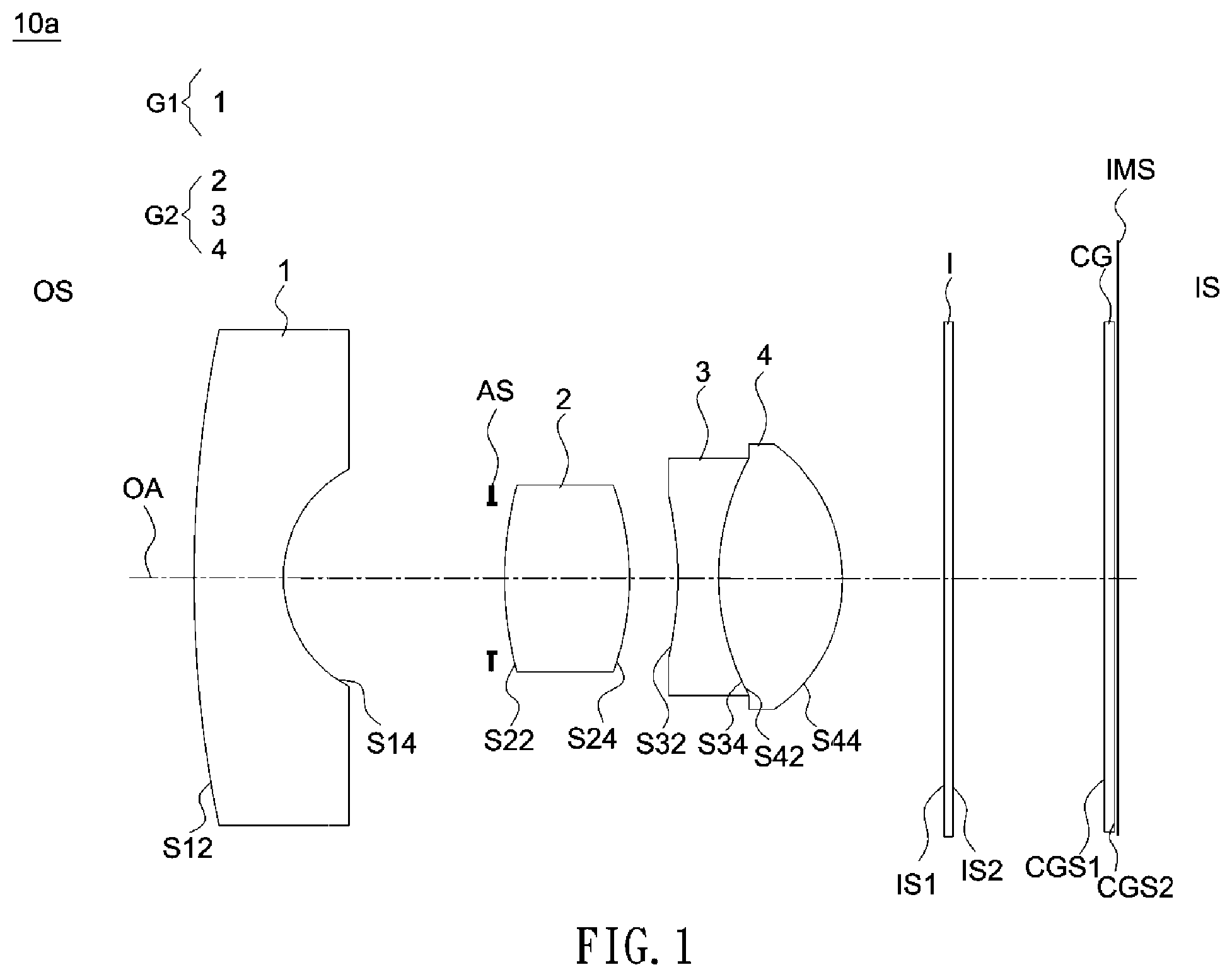
is a schematic diagram of an imaging lens according to a first embodiment of the invention. A, 2 B and 2 C show longitudinal spherical aberration curves, astigmatic field curves and a distortion curve of the imaging lens illustrated in . is a schematic diagram of an imaging lens according to a second embodiment of the invention. A, 4 B and 4 C show longitudinal spherical aberration curves, astigmatic field curves and a distortion curve of the imaging lens illustrated in . is a schematic diagram of an imaging lens according to a third embodiment of the invention. A, 6 B and 6 C show longitudinal spherical aberration curves, astigmatic field curves and a distortion curve of the imaging lens illustrated in . is a focus shift diagram of the imaging lens shown in . is a schematic diagram of an imaging lens according to a fourth embodiment of the invention. A, 9 B and 9 C show longitudinal spherical aberration curves, astigmatic field curves and a distortion curve of the imaging lens illustrated in .
DETAILED DESCRIPTION
OF THE INVENTION In the following detailed description of the preferred embodiments, directional terminology, such as “top,” “bottom,” “front.” “back,” etc., is used with reference to the orientation of the Figure(s) being described. The components of the invention can be positioned in a number of different orientations. As such, the directional terminology is used for purposes of illustration and is in no way limiting. Further, “First.” “Second,” etc., as used herein, are used as labels for nouns that they precede, and do not imply any type of ordering (e.g., spatial, temporal, logical, etc.). is a schematic diagram of an imaging lens according to a first embodiment of the invention. Referring to , an imaging lens 10 a includes, in order from an object side OS to an image side IS, a first lens 1 (the first lens 1 constituting a first lens group G 1 ), a second lens 2 , a third lens 3 , a fourth lens 4 (the second lens 2 , the third lens 3 and the fourth lens 4 constituting a second lens group G 2 ), an infrared filter I, a cover plate CG, and an aperture stop AS located between the first lens 1 and the second lens 2 . Each of the first lens 1 , the second lens 2 , the third lens 3 , and the fourth lens 4 has a refractive power. The aperture stop AS is a light-blocking element that limits the amount of light passing through the imaging lens 10 a . In other embodiment, the aperture stop AS is defined by an inner diameter of a lens barrel and thus is not an independent optical element. Light from a subject to be captured may enter the imaging lens 10 a and pass through the first lens 1 , the aperture stop AS, the second lens 2 , the third lens 3 , the fourth lens 4 , the infrared filter I and the cover plate CG in succession, and finally forms an image on an image plane IMS. The object side OS is the side provided with the subject to be captured, and the image-side IS is the side provided with the image plane IMS. In this embodiment, the first lens 1 , the second lens 2 , the third lens 3 , the fourth lens 4 , the infrared filter I and the cover plate CG respectively have object-side surfaces S 12 and S 22 , S 32 , S 42 , IS 1 , CGS 1 facing the object side OS and allowing imaging light beams to pass therethrough, and the first lens 1 , the second lens 2 , the third lens 3 , the fourth lens 4 , the infrared filter I and the cover plate CG respectively have image-side surfaces S 14 , S 24 , S 34 , S 44 , IS 2 , CGS 2 facing the image side IS and allowing imaging light beams to pass therethrough. In detail, the first lens 1 is a glass spherical lens. The first lens 1 has a negative refractive power and is a meniscus lens, where the object-side surface S 12 is convex, and the image-side surface S 14 is concave. The object-side surface S 12 and the image-side surface S 14 of the first lens 1 are spherical surfaces, but the invention is not limited thereto. The second lens 2 is a glass spherical lens. The second lens 2 has a positive refractive power. The object-side surface S 22 and the image-side surface S 24 of the second lens 2 are spherical surfaces, but the invention is not limited thereto. The third lens 3 is a plastic aspheric lens. The third lens 3 has a negative refractive power. The object-side surface S 32 and the image-side surface S 34 of the third lens 3 are aspheric surfaces, but the invention is not limited thereto. The fourth lens 4 is a plastic aspheric lens. The fourth lens 4 has a positive refractive power. The object-side surface S 42 and the image-side surface S 44 of the fourth lens 4 are aspheric surfaces. In this embodiment, the image-side surface S 34 of the third lens 3 and the object-side surface S 42 of the fourth lens 4 are connected with each other to form a compound lens, such as being cemented to each other to form a cemented lens, but the invention is not limited thereto. The infrared filter I, which is disposed on one side of the second lens group G 2 away from the first lens group G 1 , may pass the light within a wavelength range of about 360 nm to 689 nm (visible light) and block more than 97% of the light within a wavelength range of 690 nm to 750 nm. Specifically, infrared filter I may be included in an IR-Cut filter switcher that can be automatically switched. When visible light is sufficient, the infrared filter I blocks more than 97% of the light within a wavelength range of 690 nm to 750 nm; in contrast, when visible light is insufficient, the infrared filter I is deactivated to allow the light within a wavelength range of 690 nm to 750 nm to pass through. The cover plate CG may be a plate made of any suitable light-transmissive material, such as glass. The cover plate CG may function to adjust the optical path length and protect the imaging lens. In this embodiment, the imaging lens 10 a consists essentially of four lenses with refractive powers. In the first embodiment of the imaging lens 10 a , an effective focal length (EFL) is 2.76 mm, an F-number (F #) is 2.0, a diagonal field of view (DFOV) is 128.8 degrees, a total track length (TTL) is 18.51 mm, and a maximum image height is 2.92 mm. The total track length is the distance measure along the optical axis OA from the object-side surface S 12 of the first lens 1 to the image plane IMS of the imaging lens 10 a. In this embodiment, a lens diameter (outer diameter) D1 of the first lens 1 is 15.51 mm, a lens diameter DL of the fourth lens 4 is 10.97 mm, and an overall lens length LT is 13.09 mm, where the overall lens length is the distance measure along the optical axis OA between two outermost lens surfaces at opposite ends of the optical lens (e.g., between the object-side surface S 12 of the first lens 1 and the image-side surface S 44 of the fourth lens 4 ). Therefore, D1/LT=1.18, DL/LT=0.84 and EFL/LT=0.21. In one embodiment, the lens diameter is a mechanical diameter that equals a distance between opposite turning points measured in a direction perpendicular to the optical axis OA, and the lens diameter may include the span covering a clear aperture (CA) that is required for all light to pass through the field of view plus the length of an extension part that is embedded in a barrel wall at two ends for mounting the lens on a lens barrel. Detailed optical data of the imaging lens 10 a are shown in Table 1 below. In Table 1, the column with a heading “Interval/Thickness” lists each distance between two adjacent optical surfaces, which indicates a thickness of each lens or optical element on the optical axis OA or a distance along the optical axis OA between two adjacent lenses or optical elements. For example, a cell of the row with a heading “S 12 ” intersected with the column with a heading “Interval/Thickness” shows a thickness of the first lens 1 on the optical axis OA, and a cell of the row with a heading “S 14 ” intersected with the column with a heading “Interval/Thickness” shows a distance along the optical axis OA between the first lens 1 and adjacent second lens 2 . The column with a heading “Radius” lists the radius of each surface of the optical component. For example, a cell of the row with a heading “S 12 ” intersected with the column with a heading “Radius” shows half of a diameter of the object-side surface S 12 of the first lens 1 , a cell of the row with a heading “S 14 ” intersected with the column with a heading “Radius” shows half of a diameter of the image-side surface S 14 of the first lens 1 , and so on. The column with a heading “Shape” marks each lens surface as either spherical or aspherical. In addition, the column with a heading “Object” notes corresponding names of optical components. The above explanation about table headings also applies to other embodiments, thus not repeatedly described in the following for brevity. TABLE 1 Interval/ semi- Radius Thickness Refractive Abbe aperture Material Shape (mm) (mm) index number (mm) Object S12 glass spherical 27.01 1.66 1.75 52 4.58 first lens S14 spherical 2.57 4.64 2.32 AS 1.55 aperture stop S22 glass spherical 12.36 2.43 1.9 31 1.57 second S24 spherical −5.88 1.03 1.70 lens S32 plastic aspheric −12.12 0.79 1.66 20 1.69 third lens S34 aspheric 2.65 0.01 2.15 S42 plastic aspheric 2.65 2.53 1.54 56 2.16 fourth S44 aspheric −3.23 2.04 2.48 lens IS1 0.30 4.73 infrared IS2 2.73 4.73 filter CGS1 0.30 4.73 cover CGS2 0.04 4.73 plate IMS 0.00 3.16 image plane In this embodiment, the object-side surface S 32 of the third lens 3 , the image-side surface S 34 of the third lens 3 , and the object side of the fourth lens 4 S 42 and the image-side surface S 44 of the fourth lens 4 are aspheric surfaces, and these aspheric surfaces are defined according to the following equation: Z ( Y ) = Y 2 R / ( 1 + 1 - ( 1 + K ) Y 2 R 2 ) + ∑ i = 1 n a 2 i × Y 2 i ( 1 ) ↵ Where: R: a radius of curvature of part aspheric surface near the optical axis OA; Y: a vertical distance from the point on the aspheric surface to the optical axis OA; Z: a sag of the aspheric surface (a relative distance between a point on the aspheric surface spaced at a distance Y from the optical axis and the tangential plane at the aspheric surface vertex on the optical axis OA) K: the conic coefficient; and a2i: the 2i-th aspheric coefficient. Table 2 shows aspheric surface data including the conic coefficient and 2i-th order aspheric coefficients of each aspheric surface defines in the above equation. In Table 2, the field heading “S 32 ” indicates the conic coefficient and aspheric coefficients of the object-side surface S 32 of the third lens 3 , and so on. In various embodiments of the invention, the 2nd order aspheric coefficient (a2) of each aspheric surface defined in Equation (1) is 0. TABLE 2 K a4 a6 a8 a10 a12 a14 a16 S32 0 −1.07E−02 −1.40E−04 −4.62E−05 −6.52E−06 0 0 0 S34 −4.10 2.96E−03 −1.82E−03 3.23E−04 −3.52E−05 9.51E−07 −4.89E−08 0 S42 −4.10 2.96E−03 −1.82E−03 3.23E−04 −3.52E−05 9.51E−07 −4.89E−08 0 S44 −0.62 −1.01E−03 −2.88E−04 3.31E−05 1.28E−06 −1.51E−06 −1.51E−07 0 According to the above, the imaging lens 10 a meets the following conditions: the first lens 1 and the second lens 2 are glass spherical lenses, and the third lens 3 and the fourth lens 4 are aspheric plastic lenses. The refractive power of the first lens 1 is negative, the refractive power of the second lens 2 is positive, the refractive power of the third lens 3 is negative, and the refractive power of the fourth lens 4 is positive. The diagonal field of view of the imaging lens 10 a is between 120 and 140 degrees, and preferably between 125 and 130 degrees. In this embodiment, the diagonal field of view of the imaging lens 10 a is 128.8 degrees. The imaging lens 10 a according to the above embodiment has at least the following advantages. First, the first lens 1 and the second lens 2 are both glass lenses with high light transmittance to improve imaging quality and with high hardness to enhance wear resistance. Besides, the relatively low thermal expansion coefficient of a glass lens is allowed to reduce thermal drift of the imaging lens 10 a and thus enhance imaging quality. In addition, the third lens 3 and the fourth lens 4 are made of plastic to reduce manufacturing costs of the imaging lens 10 a , and the imaging lens 10 a includes two aspheric lenses to improve imaging resolution. Besides, the third lens 3 and the fourth lens 4 are cemented to form a cemented lens to correct chromatic aberrations and achieve higher manufacturing tolerances to thereby increase production yields. In this embodiment, the imaging lens 10 a may satisfy at least one of the following conditions: 2 mm<LT<20 mm, 0.8<D1/LT<1.4, 0.6<DL/LT<1 and 0.14<EFL/LT<0.4, where D1 is a lens diameter of the object-side surface of the first lens 1 , LT is a distance measure along the optical axis OA between two outermost lens surfaces at opposite ends of the optical lens (e.g., between the object-side surface S 12 of the first lens 1 and the image-side surface S 44 of the fourth lens 4 ), EFL is an effective focal length of the imaging lens 10 a , and DL is a lens diameter of the image-surface of the lens with a refractive power closest to the image side (i.e., the fourth lens 4 ). In other aspect, the imaging lens 10 a according to the above embodiment includes a first lens group G 1 and a second lens group G 2 . The first lens group G 1 includes one lens with a refractive power, and the second lens group G 2 includes three lenses with refractive powers. In detail, the first lens group G 1 includes a first lens 1 with a refractive power, and the second lens group G 2 includes a second lens 2 , a third lens 3 . The aperture stop AS of the imaging lens 10 a is disposed between the first lens group G 1 and the second lens group G 2 . Moreover, the imaging lens 10 a also meets the following conditions. The first lens group G 1 includes a glass spherical lens with a negative refractive power (i.e., the first lens 1 ), and the outermost lens surface of the first lens group G 1 towards the object side OS (i.e., the object-side surface S 12 of the first lens 1 ) is spherical, the second lens group G 2 includes two aspheric lenses (the third lens 3 with a negative refractive power and the fourth lens 4 with a positive refractive power), and the second lens group G 2 has a cemented interface (cemented by the image-side surface S 34 of third lens 3 and the object-side surface S 42 of fourth lens 4 ). The overall refractive power of the second lens group G 2 is positive. Further, in this embodiment, the imaging lens 10 a may also satisfy at least one of the following conditions: 2 mm<LT<20 mm, 0.8<D1/LT<1.4, 0.6<DL/LT<1, and 0.14<EFL/LT<0.4. The detailed numerical values of optical data of the imaging lens 10 a are summarized in Table 9. A, 2 B and 2 C show longitudinal spherical aberration curves, astigmatic field curves and a distortion curve of the imaging lens 10 a measured at wavelengths of 450 nm, 550 nm, and 650 nm. A shows the field curvature aberration measured at these wavelengths falls within ±0.05 mm over the entire field of view. B shows the field curvature aberration measured at these wavelengths falls within ±0.2 mm over the entire image height. Therefore, the imaging lens 10 a having wide viewing angles (DFOV=128.8 degrees), a large aperture (F-number=2.0), and a total track length of 18.51 mm may still provide good imaging quality. is a schematic diagram of an imaging lens according to a second embodiment of the invention. Referring to , an imaging lens 10 b includes, in order from an object side OS to an image side IS, a first lens 1 and a fifth lens 5 (the first lens 1 and the fifth lens 5 constituting a first lens group G 1 ), a second lens 2 , a third lens 3 , a fourth lens 4 (the second lens 2 , the third lens 3 and the fourth lens 4 constituting a second lens group G 2 ), an infrared filter I, a cover plate CG, and an aperture stop AS located between the first lens 1 and the second lens 2 . In this embodiment, the first lens 1 , the fifth lens 5 , the second lens 2 , the third lens 3 , the fourth lens 4 , the infrared filter I and the cover plate CG respectively have object-side surfaces S 12 , S 52 , S 22 , S 32 , S 42 , IS 1 , CGS 1 facing the object side OS and allowing imaging light beams to pass therethrough, and the first lens 1 , the fifth lens 5 , the second lens 2 , the third lens 3 , the fourth lens 4 , the infrared filter I and the cover plate CG respectively have image-side surfaces S 14 , S 54 , S 24 , S 34 , S 44 , IS 2 , CGS 2 facing the image side IS and allowing imaging light beams to pass therethrough. In detail, in this embodiment, the first lens 1 is a glass spherical lens. The first lens 1 has a negative refractive power and is a meniscus lens, where the object-side surface S 12 is convex, and the image-side surface S 14 is concave. The object-side surface S 12 and the image-side surface S 14 of the first lens 1 are spherical surfaces, but the invention is not limited thereto. The second lens 2 is a glass spherical lens. The second lens 2 has a positive refractive power. The object-side surface S 22 and the image-side surface S 24 of the second lens 2 are spherical surfaces, but the invention is not limited thereto. The third lens 3 is a plastic aspheric lens. The third lens 3 has a negative refractive power. The object-side surface S 32 and the image-side surface S 34 of the third lens 3 are aspheric surfaces, but the invention is not limited thereto. The fourth lens 4 is a plastic aspheric lens. The fourth lens 4 has a positive refractive power. The object-side surface S 42 and the image-side surface S 44 of the fourth lens 4 are aspheric surfaces, but the invention is not limited thereto. The fifth lens 5 is a plastic aspheric lens. The fifth lens 5 has a positive refractive power. The object-side surface S 52 and the image-side surface S 54 of the fifth lens 5 are aspheric surfaces, but the invention is not limited thereto. The infrared filter I, which is disposed on one side of the second lens group G 2 away from the first lens group G 1 , may pass the light within a wavelength range of about 360 nm to 689 nm (visible light) and block more than 97% of the light within a wavelength range of 690 nm to 750 nm. The cover plate CG may be a plate made of any suitable light-transmissive material, such as glass. The cover plate CG may function to adjust the optical path length and protect the imaging lens. In this embodiment, the imaging lens 10 b consists essentially of five lenses with refractive powers. In the second embodiment of the imaging lens 10 b , an effective focal length (EFL) is 3.2 mm, an F-number (F #) is 2.0, a diagonal field of view (DFOV) is 128 degrees, a total track length (TTL) is 18.5 mm, and a maximum image height is 3.38 mm. The total track length is the distance measure along the optical axis OA from the object-side surface S 12 of the first lens 1 to the image plane IMS of the imaging lens 10 b. In this embodiment, a lens diameter (outer diameter) D1 of the first lens 1 is 14 mm, a lens diameter DL of the fourth lens 4 is 11.3 mm, and an overall lens length LT is 12.9 mm, where the overall lens length is the distance measure along the optical axis OA between two outermost lens surfaces at opposite ends of the optical lens (e.g., between the object-side surface S 12 of the first lens 1 and the image-side surface S 44 of the fourth lens 4 ). Therefore, D1/LT=1.08, DL/LT=0.88 and EFL/LT=0.25. Detailed optical data of the imaging lens 10 b are shown in Table 3 below. TABLE 3 Interval/ semi- Radius Thickness Refractive Abbe aperture Material Shape (mm) (mm) index number (mm) Object S12 glass spherical 10.94 3.01 1.60 61 4.01 first lens S14 spherical 2.03 1.67 2.10 S52 plastic aspheric −8.29 2.04 1.66 20 2.00 fifth lens S54 aspheric −5.21 0.69 1.77 AS 0.81 1.73 aperture stop S22 glass spherical 13.20 1.65 1.62 63 1.90 second S24 spherical −3.96 0.10 2.10 lens S32 plastic aspheric 10.15 0.55 1.67 19 2.15 third lens S34 aspheric 2.66 0.34 2.30 S42 plastic aspheric 4.07 2.74 1.54 56 2.65 fourth S44 aspheric −6.13 1.76 2.88 lens IS1 glass spherical 0.30 1.52 64 5.00 infrared IS2 spherical 2.49 5.00 filter CGS1 glass spherical 0.30 1.52 64 5.00 cover CGS2 spherical 0.05 5.00 plate IMS 0.00 image plane Table 4 shows aspheric surface data including the conic coefficient and 2i-th order aspheric coefficients of each aspheric surface of the imaging lens 10 b . TABLE 4 K a4 a6 a8 a10 a12 a14 a16 S52 −31.52 −9.72E−03 2.18E−03 −7.17E−04 1.88E−04 −2.94E−05 1.94E−06 0.00E+0 S54 0.80 −1.08E−01 1.77E−03 7.17E−02 −7.26E−02 3.82E−02 −1.03E−02 1.11E−03 S32 −99.00 −4.60E−03 3.44E−03 −1.43E−03 2.90E−04 −3.09E−05 1.43E−06 −1.43E−08 S34 −3.22 −8.80E−03 6.25E−03 −1.99E−03 3.56E−04 −3.36E−05 1.27E−06 0.00E+0 S42 −1.27 −1.23E−02 2.60E−03 −4.51E−04 5.13E−05 −2.65E−06 4.08E−08 0.00E+0 S44 0.67 −1.55E−03 −6.83E−05 1.17E−05 1.43E−06 −5.52E−07 4.90E−08 0.00E+0 The detailed numerical values of optical data of the imaging lens 10 b are summarized in Table 9. A, 4 B and 4 C show longitudinal spherical aberration curves, astigmatic field curves and a distortion curve of the imaging lens 10 b measured at wavelengths of 450 nm, 550 nm, and 650 nm. A shows the field curvature aberration measured at these wavelengths falls within +0.05 mm over the entire field of view. B shows the field curvature aberration measured at these wavelengths falls within +0.1 mm over the entire image height. Therefore, the imaging lens 10 b having wide viewing angles (DFOV=128 degrees), a large aperture (F-number=2.0), and a total track length of 18.5 mm may still provide good imaging quality. Please refer to A to C . In the longitudinal spherical aberration scheme of A , the field curvature aberration representing the wavelength over the entire field of view falls within ±0.05 millimeters (mm). In the field curvature aberration scheme in B , the field curvature aberration representing the wavelength falls within ±0.1 millimeters (mm) over the entire height range. It can be seen that, under the conditions of having wide viewing angles with a diagonal field of view (DFOV) of 128 degrees, a large aperture with an f-number (F #) of 2.0, and a total track length (TTL) of 18.5 mm, this embodiment can still provide good imaging quality. is a schematic diagram of an imaging lens according to a third embodiment of the invention. Referring to , an imaging lens 10 c includes, in order from an object side OS to an image side IS, a first lens 1 , a fifth lens 5 , a sixth lens 6 (the first lens 1 , the fifth lens 5 and the sixth lens 6 constituting a first lens group G 1 ), a second lens 2 , a third lens 3 , a fourth lens 4 (the second lens 2 , the third lens 3 and the fourth lens 4 constituting a second lens group G 2 ), an infrared filter I, a cover plate CG, and an aperture stop AS located between the first lens 1 and the second lens 2 . In this embodiment, the first lens 1 , the fifth lens 5 , the sixth lens 6 , the second lens 2 , the third lens 3 , the fourth lens 4 , the infrared filter I and the cover plate CG respectively have object-side surfaces S 12 , S 52 , S 62 , S 22 , S 32 , S 42 , IS 1 , CGS 1 facing the object side OS and allowing imaging light beams to pass therethrough, and the first lens 1 , the fifth lens 5 , the sixth lens 6 , the second lens 2 , the third lens 3 , the fourth lens 4 , the infrared filter I and the cover plate CG respectively have image-side surfaces S 14 , S 54 , S 64 , S 24 , S 34 , S 44 , IS 2 , CGS 2 facing the image side IS and allowing imaging light beams to pass therethrough. In this embodiment, the first lens 1 is a glass spherical lens. The first lens 1 has a negative refractive power and is a meniscus lens, where the object-side surface S 12 is convex, and the image-side surface S 14 is concave. The object-side surface S 12 and the image-side surface S 14 of the first lens 1 are spherical surfaces, but the invention is not limited thereto. The second lens 2 is a glass spherical lens. The second lens 2 has a positive refractive power. The object-side surface S 22 and the image-side surface S 24 of the second lens 2 are spherical surfaces, but the invention is not limited thereto. The third lens 3 is a plastic aspheric lens. The third lens 3 has a negative refractive power. The object-side surface S 32 and the image-side surface S 34 of the third lens 3 are aspheric surfaces, but the invention is not limited thereto. The fourth lens 4 is a plastic aspheric lens. The fourth lens 4 has a positive refractive power. The object-side surface S 42 and the image-side surface S 44 of the fourth lens 4 are aspheric surfaces, the object-side surface S 42 of the fourth lens 4 has at least one inflection point, but the invention is not limited thereto. The fifth lens 5 is a plastic aspheric lens. The fifth lens 5 has a positive refractive power. The object-side surface S 52 and the image-side surface S 54 of the fifth lens 5 are aspheric surfaces, but the invention is not limited thereto. The sixth lens 6 is a plastic aspheric lens. The sixth lens 6 has a positive refractive power. The object-side surface S 62 and the image-side surface S 64 of the sixth lens 6 are aspheric surfaces, but the invention is not limited thereto. The infrared filter I, which is disposed on one side of the second lens group G 2 away from the first lens group G 1 , may pass the light within a wavelength range of about 360 nm to 689 nm (visible light) and block more than 97% of the light within a wavelength range of 690 nm to 750 nm. The cover plate CG may be a plate made of any suitable light-transmissive material, such as glass. The cover plate CG may function to adjust the optical path length and protect the imaging lens. In this embodiment, the imaging lens 10 c consists essentially of five lenses with refractive powers. In the third embodiment of the imaging lens 10 c , an effective focal length (EFL) is 3.19 mm, an F-number (F #) is 2.0, a diagonal field of view (DFOV) is 127.6 degrees, a total track length (TTL) is 18.5 mm, and a maximum image height is 3.378 mm. The total track length is the distance measure along the optical axis OA from the object-side surface S 12 of the first lens 1 to the image plane IMS of the imaging lens 10 c. In this embodiment, a lens diameter (outer diameter) D1 of the first lens 1 is 16.68 mm, a lens diameter DL of the fourth lens 4 is 12.18 mm, and an overall lens length LT is 14.7 mm, where the overall lens length is the distance measure along the optical axis OA between two outermost lens surfaces at opposite ends of the optical lens (e.g., between the object-side surface S 12 of the first lens 1 and the image-side surface S 44 of the fourth lens 4 ). Therefore, D1/LT=1.13, DL/LT=0.83 and EFL/LT=0.22. Detailed optical data of the imaging lens 10 c are shown in Table 5 below. TABLE 5 Interval/ semi- Radius Thickness Refractive Abbe aperture Material Shape (mm) (mm) index number (mm) Object S12 glass spherical 12.98 3.52 1.77 49.62 5.42 first lens S14 spherical 1.93 1.47 1.80 S52 plastic aspheric −12.33 1.84 1.54 55.71 1.79 fifth lens S54 aspheric −6.87 0.10 1.79 S62 plastic aspheric −34.92 0.58 1.66 20.36 1.63 sixth lens S64 aspheric −6.59 0.38 1.68 AS 1.10 1.57 S22 glass spherical 5.54 1.38 1.61 60.61 2.10 second S24 spherical −4.41 0.27 2.15 lens S32 plastic aspheric −6.06 0.76 1.66 20.36 2.10 third lens S34 aspheric 5.04 0.42 2.40 S42 plastic aspheric 3.41 2.89 1.54 55.71 2.90 fourth S44 aspheric −10.57 1.18 3.32 lens IS1 glass 0.30 1.52 64.14 5.78 infrared IS2 1.92 5.78 filter CGS1 glass 0.30 1.52 64.14 5.78 cover CGS2 0.09 5.78 plate IMS 0.00 image plane Table 6 shows aspheric surface data including the conic coefficient and 2i-th order aspheric coefficients of each aspheric surface of the imaging lens 10 c . TABLE 6 K a4 a6 a8 a10 a12 a14 a16 S52 −6.33 −7.20E−03 −1.08E−03 4.45E−04 −1.27E−04 1.73E−20 0.00E+00 0.00E+00 S54 2.66 −2.88E−02 2.19E−03 6.95E−05 −1.92E−05 2.75E−20 0.00E+00 0.00E+00 S62 0.00 −2.55E−02 −5.82E−04 −9.16E−04 2.86E−04 2.16E−20 0.00E+00 0.00E+00 S64 −19.84 −1.37E−02 −1.92E−03 −2.93E−04 1.29E−04 2.42E−20 0.00E+00 0.00E+00 S32 4.87 −4.14E−04 −3.85E−04 3.20E−05 1.31E−05 0.00E+00 0.00E+00 0.00E+00 S34 −11.84 2.77E−03 −5.50E−04 1.16E−04 −7.44E−06 1.59E−19 0.00E+00 0.00E+00 S42 −5.51 5.04E−04 −3.48E−04 3.23E−05 −1.99E−06 8.80E−20 0.00E+00 0.00E+00 S44 0.00 −1.39E−03 −3.64E−04 8.07E−05 −1.22E−05 8.95E−07 −2.77E−08 0.00E+00 The detailed numerical values of optical data of the imaging lens 10 c are summarized in Table 9. A, 6 B and 6 C show longitudinal spherical aberration curves, astigmatic field curves and a distortion curve of the imaging lens 10 c measured at wavelengths of 450 nm, 550 nm, and 650 nm. A shows the field curvature aberration measured at these wavelengths falls within +0.08 mm over the entire field of view. B shows the field curvature aberration measured at these wavelengths falls within +0.1 mm over the entire image height. Therefore, the imaging lens 10 b having wide viewing angles (DFOV=127.6 degrees), a large aperture (F-number=2.0), and a total track length of 18.5 mm may still provide good imaging quality. is a focus shift diagram illustrating the focus shift of the imaging lens 10 c measured at different wavelengths. In , the 550 nm visible light may pass the imaging lens 10 c to form a first focal plane, the first focal plane may cross an optical axis of the imaging lens 10 c to form a first intersection, the 850 nm infrared light may pass the imaging lens 10 c to form a second focal plane, and the second focal plane may cross the optical axis of the imaging lens 10 c to form a second intersection. A displacement between the first intersection and the second intersection is referred to as a focus shift. It can be clearly seen from that the focus shift is smaller than 15 μm. The simulated results shown in achieve a focus shift of less than 20 μm and thus are within permitted ranges specified by the standard, which indicates the above embodiment of imaging lens 10 c may achieve good imaging quality and 24-hours confocal image-capturing capability. is a schematic diagram of an imaging lens according to a fourth embodiment of the invention. Referring to , an imaging lens 10 d includes, in order from an object side OS to an image side IS, a first lens 1 and a fifth lens 5 (the first lens 1 and the fifth lens 5 constituting a first lens group G 1 ), a second lens 2 , a third lens 3 (the second lens 2 and the third lens 3 constituting a second lens group G 2 ), an infrared filter I, a cover plate CG, and an aperture stop AS located between the first lens 1 and the second lens 2 . The aperture stop AS is a light-blocking element that limits the amount of light passing through the imaging lens 10 d . Light from a subject to be captured may enter the imaging lens 10 d and pass through the first lens 1 , the fifth lens 5 , the aperture stop AS, the second lens 2 , the third lens 3 , the infrared filter I and the cover plate CG in succession, and finally forms an image on an image plane IMS. The object side OS is the side provided with the subject to be captured, and the image-side IS is the side provided with the image plane IMS. In this embodiment, the first lens 1 , the fifth lens 5 , the second lens 2 , the third lens 3 , the infrared filter I and the cover plate CG respectively have object-side surfaces S 12 , S 52 , S 22 , S 32 , IS 1 , CGS 1 facing the object side OS and allowing imaging light beams to pass therethrough, and the first lens 1 , the fifth lens 5 , the second lens 2 , the third lens 3 , the infrared filter I and the cover plate CG respectively have image-side surfaces S 14 , S 54 , S 24 , S 34 , IS 2 , CGS 2 facing the image side IS and allowing imaging light beams to pass therethrough. In detail, In this embodiment, the first lens 1 is a glass spherical lens. The first lens 1 has a negative refractive power and is a meniscus lens, where the object-side surface S 12 is convex, and the image-side surface S 14 is concave. The object-side surface S 12 and the image-side surface S 14 of the first lens 1 are spherical surfaces, but the invention is not limited thereto. The fifth lens 5 is a glass spherical lens. The fifth lens 5 has a positive refractive power. The object-side surface S 52 and the image-side surface S 54 of the fifth lens 5 are spherical surfaces, but the invention is not limited thereto. The second lens 2 is a plastic aspheric lens. The second lens 2 has a positive refractive power. The object-side surface S 22 and the image-side surface S 24 of the second lens 2 are aspheric surfaces, but the invention is not limited thereto. The third lens 3 is a plastic aspheric lens. The third lens 3 has a negative refractive power. The object-side surface S 32 and the image-side surface S 34 of the third lens 3 are aspheric surfaces, but the invention is not limited thereto. In this embodiment, the image-side surface S 24 of the second lens 2 and the object-side surface S 32 of the third lens 3 are connected with each other to form a compound lens, such as being cemented to each other to form a cemented lens, but the invention is not limited thereto. The infrared filter I, which is disposed on one side of the second lens group G 2 away from the first lens group G 1 , may pass the light within a wavelength range of about 360 nm to 689 nm (visible light) and block more than 97% of the light within a wavelength range of 690 nm to 750 nm. The cover plate CG may be a plate made of any suitable light-transmissive material, such as glass. The cover plate CG may function to adjust the optical path length and protect the imaging lens. In this embodiment, the imaging lens 10 d consists essentially of four lenses with refractive powers. In the fourth embodiment of the imaging lens 10 d , an effective focal length (EFL) is 2.81 mm, an F-number (F #) is 2.0, a diagonal field of view (DFOV) is 129.9 degrees, a total track length (TTL) is 19.5 mm, and a maximum image height is 2.92 mm. The total track length is the distance measure along the optical axis OA from the object-side surface S 12 of the first lens 1 to the image plane IMS of the imaging lens 10 d. In this embodiment, a lens diameter (outer diameter) D1 of the first lens 1 is 14.96 mm, a lens diameter DL of the third lens 3 is 11.34 mm, and an overall lens length LT is 15.12 mm, where the overall lens length is the distance measure along the optical axis OA between two outermost lens surfaces at opposite ends of the optical lens (e.g., between the object-side surface S 12 of the first lens 1 and the image-side surface S 34 of the third lens 3 ). Therefore, D1/LT=0.99, DL/LT=0.75 and EFL/LT=0.19. Detailed optical data of the imaging lens 10 d are shown in Table 7 below. TABLE 7 Interval/ semi- Radius Thickness Refractive Abbe aperture Material Shape (mm) (mm) index number (mm) Object S12 glass spherical 38.85 0.50 1.64 61 4.32 first lens S14 spherical 2.90 4.62 2.65 S52 glass spherical −6.03 2.57 1.75 52 1.89 aperture stop S54 spherical −5.02 0.10 1.88 second AS 0.29 1.70 lens S22 plastic aspheric 4.55 6.30 1.54 57 2.18 third S24 aspheric −2.11 0.01 2.43 lens S32 plastic aspheric −2.11 0.75 1.66 20 2.43 fourth S34 aspheric −5.27 0.10 2.63 lens IS1 0.30 5.00 infrared IS2 2.73 5.00 filter CGS1 0.30 5.00 cover CGS2 0.95 5.00 plate IMS 0.00 3.16 image plane Table 8 shows aspheric surface data including the conic coefficient and 2i-th order aspheric coefficients of each aspheric surface of the imaging lens 10 d . TABLE 8 K a4 a6 a8 a10 a12 a14 a16 S32 −0.09 −3.55E−04 −5.12E−04 6.01E−04 −3.55E−04 1.11E−04 −1.77E−05 1.12E−06 S34 −0.35 −3.22E−03 −2.99E−03 3.04E−03 −7.54E−04 1.23E−04 −1.33E−05 7.56E−07 S42 −0.35 −3.22E−03 −2.99E−03 3.04E−03 −7.54E−04 1.23E−04 −1.33E−05 7.56E−07 S44 −18.81 −1.42E−02 4.18E−03 −9.53E−04 1.99E−04 −2.85E−05 2.33E−06 −7.97E−08 The imaging lens 10 d according to the above embodiment has at least the following advantages. First, the first lens 1 and the fifth lens 5 are both glass lenses with high light transmittance to improve imaging quality and with high hardness to enhance wear resistance. Besides, the relatively low thermal expansion coefficient of a glass lens is allowed to reduce thermal drift of the imaging lens 10 d and thus enhance imaging quality. In addition, the imaging lens 10 d includes two aspheric lenses to improve imaging resolution. Besides, the second lens 2 and the third lens 3 are cemented to form a cemented lens to correct chromatic aberrations and achieve higher manufacturing tolerances to thereby increase production yields. The detailed numerical values of optical data of the imaging lens 10 d are summarized in Table 9. Table 9 lists relevant numerical values of the imaging lens 10 a - 10 d in the first to the fourth embodiments. Among them, the items “EFL”, “TTL”, “LT”, “Image Height”, “D1” and “DL” are measured in millimeters (mm), and the unit of the item “DFOV” is degree. TABLE 9 First Second Third Fourth embodiment embodiment embodiment embodiment EFL 2.76 3.20 3.19 2.81 F# 2.0 2.0 2.0 2.0 DFOV 128.8 128.0 127.6 129.9 TTL 18.51 12.90 18.50 19.50 Image Height 2.92 3.38 3.38 2.92 D1 15.51 14.00 16.68 14.96 DL 10.97 11.30 12.18 11.34 LT 13.09 12.90 14.70 15.12 D1/LT 1.18 1.08 1.13 0.99 DL/LT 0.84 0.88 0.83 0.75 EFL/LT 0.21 0.25 0.22 0.19 A, 9 B and 9 C show longitudinal spherical aberration curves, astigmatic field curves and a distortion curve of the imaging lens 10 d measured at wavelengths of 450 nm, 550 nm, and 650 nm. A shows the field curvature aberration measured at these wavelengths falls within ±0.05 mm over the entire field of view. B shows the field curvature aberration measured at these wavelengths falls within ±0.05 mm over the entire image height. Therefore, the imaging lens 10 b having wide viewing angles (DFOV=129.9 degrees), a large aperture (F-number=2.0), and a total track length of 19.5 mm may still provide good imaging quality. According to the above embodiments, meeting the designed characteristics and arrangement of optical components set forth in the above may achieve good imaging quality, 24-hours confocal image-capturing capability and a miniaturized assembly under the condition of a wide field of view and a large effective aperture. Further, in various embodiments of the invention, the glass/plastic lenses and spherical/aspheric lenses are well matched to achieve a wide range of operating temperature, low fabrication costs and improved imaging quality. Though the embodiments of the invention have been presented for purposes of illustration and description, they are not intended to be exhaustive or to limit the invention. Accordingly, many modifications and variations without departing from the spirit of the invention or essential characteristics thereof will be apparent to practitioners skilled in this art. It is intended that the scope of the invention be defined by the claims appended hereto and their equivalents in which all terms are meant in their broadest reasonable sense unless otherwise indicated.
Figures (9)
Citations
This patent cites (1)
- US111323893