Abstract
A vehicle drive device includes a rotating electric machine disposed on a first axis, an output gear mechanism and an output member disposed on a second axis, and a case that houses these elements. The second axis is disposed below the first axis, a suction port of an oil pump is disposed below the first axis and the second axis and between the first axis and the second axis in a width direction, an outermost gear is disposed so that a direction of rotation at a lower end portion of the outermost gear during forward movement of a vehicle points toward the suction port, and a part of a peripheral wall section of the case that faces a lower surface of the rotating electric machine is inclined downward toward the suction port.
Claims (14)
1 . A vehicle drive device comprising: a rotating electric machine disposed on a first axis; an output member disposed on a second axis, which differs from the first axis, and in driving connection with a wheel; a power transmission mechanism configured to transmit torque of the rotating electric machine to the output member; a case configured to house the rotating electric machine and the power transmission mechanism; and an oil pump including a suction port, and configured to expel oil drawn in from the suction port, and to supply oil for cooling to the rotating electric machine, wherein the power transmission mechanism includes an output gear mechanism disposed on the second axis, the case includes a peripheral wall section surrounding the rotating electric machine and the output gear mechanism, with (i) a direction parallel to the first axis and the second axis being an axial direction, (ii) a direction perpendicular to a vertical direction in an axial direction view along the axial direction in a state where the vehicle drive device has been mounted in a vehicle being a width direction, and (iii) a gear disposed in an outermost periphery of the output gear mechanism being an outermost gear, the second axis is disposed below the first axis, the suction port is disposed between the first axis and the second axis in the width direction, and is disposed below the first axis and the second axis in the vertical direction, the outermost gear is disposed so that a direction of rotation at a lower end portion of the outermost gear while the vehicle is moving forward points toward the suction port in the width direction, and a facing portion of an inner surface of the peripheral wall section facing a lower surface of the rotating electric machine is downwardly inclined in the width direction toward the suction port, and the suction port is disposed below the facing portion so as to cause oil dropped from the rotating electric machine to flow down along the facing portion toward the suction port, wherein the facing portion overlaps the rotating electric machine when viewed along the vertical direction.
Show 13 dependent claims
2 . The vehicle drive device according to claim 1 , wherein the oil pump further includes a strainer for passing the oil that has been drawn in from the suction port, and the strainer is inserted into an opening formed in the case in a direction intersecting the axial direction, and is fixed in position.
3 . The vehicle drive device according to claim 1 , wherein in the axial direction view, the suction port is disposed adjacent to the lower end portion of the outermost gear in the width direction and upwardly adjacent to a bottom surface of the peripheral wall section.
4 . The vehicle drive device according to claim 1 , wherein the vehicle drive device further includes a first plate disposed between the lower end portion of the outermost gear and the suction port in the width direction, the first plate extending along a tangential direction at a lower end portion of the outermost gear.
5 . The vehicle drive device according to claim 1 , wherein the vehicle drive device further includes a second plate disposed between a lower end portion of the outermost gear and the suction port in the width direction, the second plate extending in a direction intersecting a flow of oil caused by rotation of the outermost gear.
6 . The vehicle drive device according to claim 1 , wherein the case forms at least a first housing space, in which the rotating electric machine is housed, and a third housing space, in which at least part of the power transmission mechanism is disposed, and includes a support wall for partitioning the first housing space and the third housing space in the axial direction, and the support wall includes a communication hole communicating the first housing space with the third housing space.
7 . The vehicle drive device according to claim 6 , wherein, separately from the communication hole, the support wall further includes an oil return hole for returning oil from the first housing space to the third housing space, and the oil return hole is disposed radially inward of the outermost gear.
8 . The vehicle drive device according to claim 1 , comprising, as the rotating electric machine, a first rotating electric machine and a second rotating electric machine, and comprising, as the output member, a first output member in driving connection with a first wheel and a second output member in driving connection with a second wheel, wherein the power transmission mechanism further includes: a first gear coupled to rotate integrally with a rotor of the first rotating electric machine; a second gear coupled to rotate integrally with a rotor of the second rotating electric machine; a first counter gear mechanism including a third gear meshing with the first gear and a fourth gear rotating integrally with the third gear; and a second counter gear mechanism including a fifth gear meshing with the second gear and a sixth gear integrally rotating with the fifth gear, the output gear mechanism includes a seventh gear meshing with the fourth gear and an eighth gear meshing with the sixth gear, and at least one of the seventh gear and the eighth gear is the outermost gear.
9 . The vehicle drive device according to claim 8 , wherein the output gear mechanism distributes and transmits driving force transmitted from the first rotating electric machine and the second rotating electric machine to the first output member and the second output member, the vehicle drive device includes a configuration in which: a region in the axial direction where the output gear mechanism is disposed and a region in the axial direction where the first rotating electric machine is disposed overlap; and a region in the axial direction where the oil pump is disposed and a region in the axial direction where the second rotating electric machine is disposed overlap.
10 . The vehicle drive device according to claim 8 , wherein the case forms a first housing space in which the first rotating electric machine is housed in the axial direction, a second housing space in which the second rotating electric machine is housed in the axial direction, and a third housing space that is provided between the first housing space and the second housing space in the axial direction and in which at least part of the power transmission mechanism is disposed, and the suction port is disposed in the third housing space in a state where the suction port communicates with both the first housing space and the second housing space.
11 . The vehicle drive device according to claim 1 , further comprising an oil supplying section configured to supply oil to the rotating electric machine, and wherein the oil supplying section is provided above the rotating electric machine as a pair of sections split between both sides of the first axis in the width direction.
12 . The vehicle drive device according to claim 1 , comprising, as the rotating electric machine, a first rotating electric machine including a first rotor and a second rotating electric machine including a second rotor, wherein the vehicle drive device further includes a shared oil supplying path for supplying oil to an inside of a hollow first rotor shaft connected to the first rotor and to an inside of a hollow second rotor shaft connected to the second rotor between the first rotating electric machine and the second rotating electric machine in the axial direction of the case.
13 . The vehicle drive device according to claim 12 , wherein the vehicle drive device further includes plugs for adjusting a flow of oil, respectively at a portion of the shared oil supplying path connected to the first rotor shaft and a portion of the shared oil supplying path connected to the second rotor shaft.
14 . The vehicle drive device according to claim 1 , wherein the case includes an end wall section that covers one end portion in the axial direction, the end wall section rotatably supports a rotor shaft connected to the rotor of the rotating electric machine via a rotor bearing, and the end wall section includes a bearing oil supplying path for supplying oil to the rotor bearing along the end wall section.
Full Description
Show full text →
TECHNICAL FIELD
The disclosure here relates to a vehicle drive device.
BACKGROUND ART
A vehicle drive device currently in use includes a rotating electric machine, an output member that is in driving connection with a wheel or wheels, a power transmission mechanism that transmits the torque of the rotating electric machine to the output member; and a case that houses the rotating electric machine and the power transmission mechanism. This vehicle drive device is further provided with an oil pump for cooling the rotating electric machine, for example. An oil pump usually includes a strainer for removing foreign matter present in the oil, expels oil that has been drawn in through a suction port of the strainer, and supplies the oil to the rotating electric machine and the like.
One example of this type of vehicle drive device is disclosed in JP2013-52849A (Patent Document 1). In the vehicle drive device of Patent Document 1, a strainer (the “strainer 71 ”) is disposed at a position directly above the flat bottom surface of the case (the “case 11”). The suction port (or “suction port 71 b ”) of the strainer, which serves as the suction port of the oil pump, is disposed near the center in both the front-rear direction and the left-right direction. This means that even if the oil level becomes tilted due to the vehicle accelerating, decelerating, or turning, it is possible to avoid exposure of the suction port above the oil level, which prevents the production of air bubbles in the oil.
However, if the speed at which oil returns to the vicinity of the suction port of the oil pump after cooling the rotating electric machine is slower than the speed at which the oil pump draws in and expels oil, the supplying of oil to the oil pump may not keep up, resulting in an actual risk of air bubbles being produced. No countermeasures for this risk are taken in Patent Document 1.
PRIOR ART DOCUMENTS
Patent Documents
• Patent Document 1: JP2013-52849A
DISCLOSURE
Problem to be Solved
For this reason, there is demand for a vehicle drive device that can effectively suppress the production of air bubbles at an oil pump.
Means for Solving Problem
A vehicle drive device according to an aspect of the present disclosure includes:
•
• a rotating electric machine disposed on a first axis; • an output member disposed on a second axis, which differs from the first axis, and in driving connection with a wheel; • a power transmission mechanism configured to transmit torque of the rotating electric machine to the output member; • a case configured to house the rotating electric machine and the power transmission mechanism; and • an oil pump including a suction port, and configured to expel oil drawn in from the suction port, and to supply oil for cooling to the rotating electric machine, • wherein the power transmission mechanism includes an output gear mechanism disposed on the second axis, • the case includes a peripheral wall section surrounding the rotating electric machine and the output gear mechanism, • with (i) a direction parallel to the first axis and the second axis being an axial direction, (ii) a direction perpendicular to a vertical direction in an axial direction view along the axial direction in a state where the vehicle drive device has been mounted in a vehicle being a width direction, and (iii) a gear disposed in an outermost periphery of the output gear mechanism being an outermost gear, • the second axis is disposed below the first axis, • the suction port is disposed between the first axis and the second axis in the width direction, and is disposed below the first axis and the second axis in the vertical direction, • the outermost gear is disposed so that a direction of rotation at a lower end portion of the outermost gear while the vehicle is moving forward points toward the suction port in the width direction, and • a portion of an inner surface of the peripheral wall section facing a lower surface of the rotating electric machine is downwardly inclined in the width direction toward the suction port.
According to this configuration, the first axis is disposed in a direction pointed to by the direction of rotation of the lower end portion of the outermost gear, which is disposed on the second axis, when the vehicle is moving forward, and the suction port is disposed between the first axis and the second axis. This makes it possible to efficiently collect oil transported by the rotating outermost gear at the suction port. Since the inner surface part of the peripheral wall section facing the lower surface of the rotating electric machine is downwardly inclined toward the suction port, oil that has cooled the rotating electric machine can be received by the inner surface of the peripheral wall section and caused to flow down toward the suction port. By drawing in both the oil transported by the outermost gear on the second axis and the oil flowing down from the rotating electric machine side on the first axis from the suction port, it is possible to supply a sufficient amount of oil to the oil pump. Accordingly it is possible to effectively prevent the production of air bubbles at the air pump (that is, the drawing in of air at the oil pump).
These and other advantages and features of the technology according to the present disclosure will become more apparent from the following description of the embodiments, which refer to the accompanying drawings and are exemplary and non-limiting.
BRIEF DESCRIPTION OF THE DRAWINGS
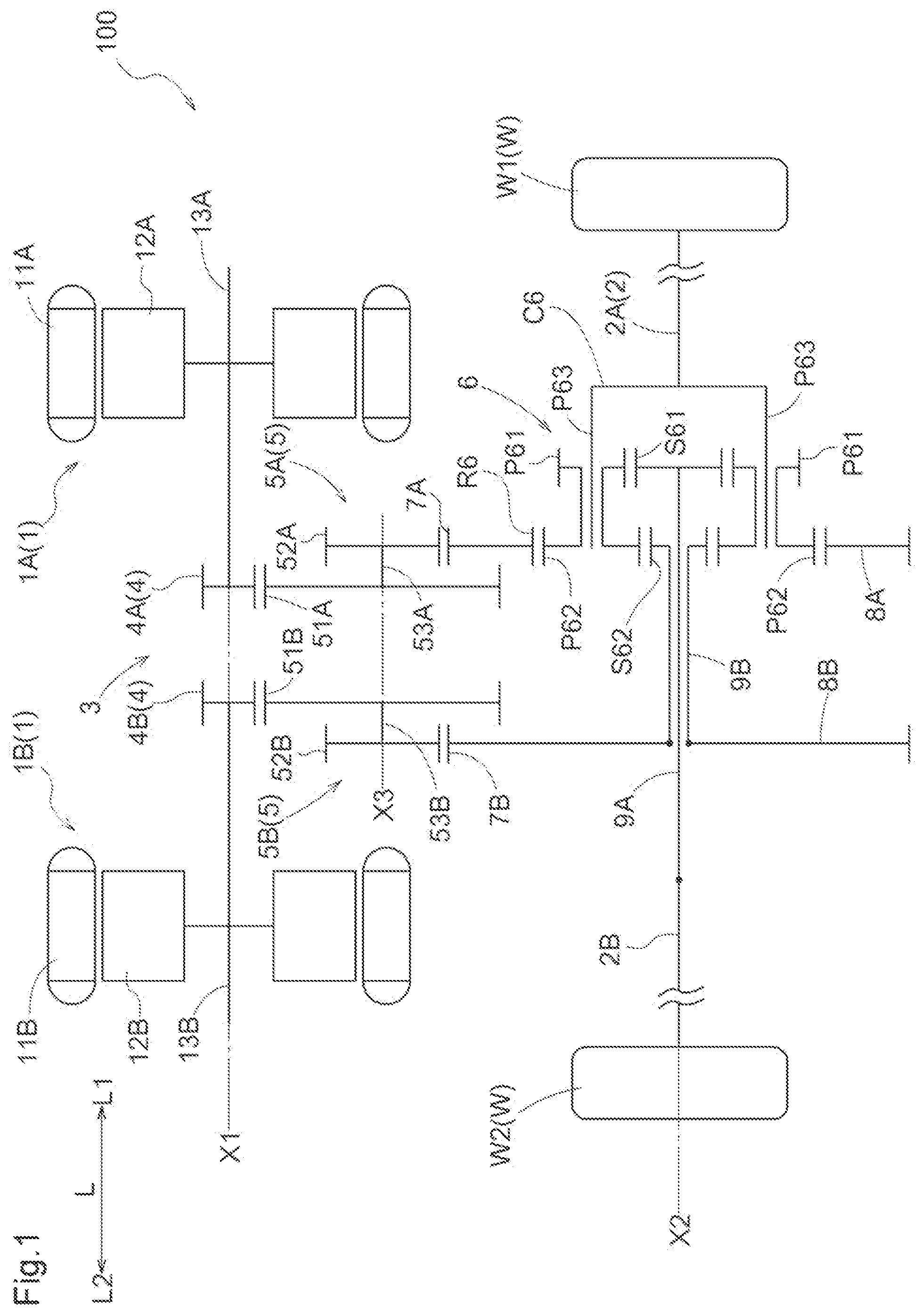
is a skeleton diagram of a vehicle drive device according to a first embodiment.
is a cross-sectional view of the vehicle drive device.
is a side view of a first housing space side of a case interior.
is a perspective view of a first housing space side of a case interior.
is a partially cutaway front view of a vehicle drive device.
is an exploded perspective view depicting a mounted state of a strainer.
is a cross-sectional view of a vehicle drive device according to a second embodiment.
is a view of a first support wall as viewed in the axial direction.
is a view of a second support wall as viewed in the axial direction.
is a side view of a third housing space side of a case interior.
DETAILED DESCRIPTION
First Embodiment
A first embodiment of a vehicle drive device will now be described with reference to the drawings. As depicted in , a vehicle drive device 100 includes rotating electric machines 1 , output members 2 that are in driving connection with wheels W, a power transmission mechanism 3 , and an oil pump 20 . In the present embodiment, a first rotating electric machine 1 A and a second rotating electric machine 1 B are provided as the rotating electric machines 1 . A first output member 2 A that is in driving connection with a first wheel W 1 that is a first example of the wheels W and a second output member 2 B that is in driving connection with a second wheel W 2 that is a second example of the wheels W are provided as the output member 2 .
The power transmission mechanism 3 is equipped with a first input gear 4 A, a second input gear 4 B, a first counter gear mechanism 5 A, a second counter gear mechanism 5 B, and a differential gear mechanism 6 . In this way the vehicle drive device 100 according to the present embodiment is equipped with the first rotating electric machine 1 A, the second rotating electric machine 1 B, the first output member 2 A, the second output member 2 B, the first input gear 4 A, the second input gear 4 B, the first counter gear mechanism 5 A, the second counter gear mechanism 5 B, and the differential gear mechanism 6 . The vehicle drive device 100 includes a case CS that houses these components. Note that parts of the first output member 2 A and the second output member 2 B are exposed outside the case CS.
In this specification, the expression “rotating electric machine” is used as a concept including electric motors, electric generators, and motor-generators that function as both motors and generators as necessary.
The expression “in driving connection” refers to a state in which two rotating elements are connected in a manner that enables a driving force to be transmitted. This concept includes a state in which the two rotating elements are connected to rotate integrally and a state in which the two rotating elements are connected in a manner that enables a driving force to be transmitted via one or more transmission members. Such transmission members may include various members (shafts, gear mechanisms, belts, chains, and the like) that transmit rotational motion at the same speed or at a different speed, and engagement devices (devices that use frictional engagement, devices that engage through meshing, and the like) that selectively transmit rotational motion and a driving force.
The first rotating electric machine 1 A and the second rotating electric machine 1 B are disposed on a first axis X 1 . The first output member 2 A and the second output member 2 B are disposed on a second axis X 2 that differs from the first axis X 1 . The first counter gear mechanism 5 A and the second counter gear mechanism 5 B are disposed on a third axis X 3 that differs from the first axis X 1 and the second axis X 2 . The first axis X 1 , the second axis X 2 , and the third axis X 3 are disposed parallel to each other, and a direction parallel to these axes is referred to as the “axial direction L”. In the present embodiment, the side where the first rotating electric machine 1 A is disposed, which is also one side in the axial direction L, is referred to as the “axial direction-first side L 1 ”, and the other side (that is, the side where the second rotating electric machine 1 B is disposed) on the opposite side is referred to as the “axial direction-second side L 2 ”. Also, in the following description, a state when looking along the axial direction L is referred to as an “axial direction view”.
In a state (or “vehicle mounted state”) where the vehicle drive device 100 has been mounted in a vehicle, a direction perpendicular to the vertical direction in an axial direction view is referred to as the “width direction H” (see ). In the present embodiment, the side in the width direction H where the first axis X 1 (that is, the first rotating electric machine 1 A and the second rotating electric machine 1 B) is disposed is referred to as the “width direction-first side H 1 ” and the other side (that is, the side where the differential gear mechanism 6 is disposed) that is opposite is referred to as the “width direction-second side H 2 ”. Note that in the present embodiment, the width direction H matches the front-rear direction for the vehicle, the width direction-first side H 1 is the rear side of the vehicle, and the width direction-second side H 2 is the front side of the vehicle.
The first rotating electric machine 1 A includes a first stator 11 A, which is fixed to the case CS, and a first rotor 12 A, which is rotatably supported at a position radially inward of the first stator 11 A. The first rotating electric machine 1 A is powered by being supplied with electric power from a power storage device (not illustrated) and also supplies electric power generated by inertia of the vehicle or the like to the power storage device to charge the power storage device. The first rotor 12 A is connected to integrally rotate with a first rotor shaft 13 A. The first input gear 4 A is formed on an outer surface at an axial direction-second side L 2 part of the first rotor shaft 13 A. In this way, the first input gear 4 A is connected to rotate integrally with the first rotor 12 A. In the present embodiment, the first input gear 4 A corresponds to a “first gear” for the present disclosure.
The second rotating electric machine 1 B includes a second stator 11 B, which is fixed to the case CS, and a second rotor 12 B, which is rotatably supported at a position radially inward of the second stator 11 B. The second rotating electric machine 1 B is powered by being supplied with electric power from a power storage device (not illustrated) and also supplies electric power generated by inertia of the vehicle or the like to the power storage device to charge the power storage device. The second rotor 12 B is connected to integrally rotate with a second rotor shaft 13 B. The second input gear 4 B is formed on an outer surface at an axial direction-first side L 1 part of the second rotor shaft 13 B. In this way, the second input gear 4 B is connected to rotate integrally with the second rotor 12 B. In the present embodiment, the second input gear 4 B corresponds to a “second gear” for the present disclosure.
The power transmission mechanism 3 transmits the torque of the rotating electric machines 1 to the output members 2 . In the present embodiment, the power transmission mechanism 3 transmits the torque of the first rotating electric machine 1 A and the second rotating electric machine 1 B to the first output member 2 A and the second output member 2 B. The power transmission mechanism 3 includes the first input gear 4 A and the second input gear 4 B, the first counter gear mechanism 5 A, the second counter gear mechanism 5 B, and the differential gear mechanism 6 mentioned earlier.
The first counter gear mechanism 5 A includes a first counter input gear 51 A, a first counter output gear 52 A, and a first counter shaft 53 A. The first counter input gear 51 A is an input element of the first counter gear mechanism 5 A. The first counter input gear 51 A meshes with the first input gear 4 A. The first counter output gear 52 A is an output element of the first counter gear mechanism 5 A. The first counter output gear 52 A is connected via a first counter shaft 53 A in such a manner as to rotate integrally with the first counter input gear 51 A. In the present embodiment, the first counter input gear 51 A corresponds to a “third gear” for the present disclosure, and the first counter output gear 52 A corresponds to a “fourth gear” for the present disclosure.
In the present embodiment, the first counter input gear 51 A is formed with a larger diameter than the first counter output gear 52 A. The first counter output gear 52 A is disposed on the axial direction-first side L 1 of the first counter input gear 51 A. The first counter output gear 52 A meshes with a first differential input gear 7 A formed on a first connecting member 8 A and is thereby in driving connection with the differential gear mechanism 6 .
The second counter gear mechanism 5 B includes a second counter input gear 51 B, a second counter output gear 52 B, and a second counter shaft 53 B. The second counter input gear 51 B is an input element of the second counter gear mechanism 5 B. The second counter input gear 51 B meshes with the second input gear 4 B. The second counter output gear 52 B is an output element of the second counter gear mechanism 5 B. The second counter output gear 52 B is connected via a second counter shaft 53 B in such a manner as to rotate integrally with the second counter input gear 51 B. In the present embodiment, the second counter input gear 51 B corresponds to a “fifth gear” for the present disclosure, and the second counter output gear 52 B corresponds to a “sixth gear” for the present disclosure.
In the present embodiment, the second counter input gear 51 B is formed with a larger diameter than the second counter output gear 52 B. The second counter output gear 52 B is disposed on the axial direction-second side L 2 of the second counter input gear 51 B. The second counter output gear 52 B meshes with a second differential input gear 7 B formed on a second connecting member 8 B and is thereby in driving connection with the differential gear mechanism 6 .
The differential gear mechanism 6 provides a driving connection between the first counter output gear 52 A and second counter output gear 52 B and the first output member 2 A and second output member 2 B. The differential gear mechanism 6 includes the first differential input gear 7 A, the second differential input gear 7 B, and a planetary gear mechanism including four rotating elements, that is, a first sun gear S 61 , a second sun gear S 62 , a carrier C 6 , and a ring gear R 6 . In the present embodiment, the differential gear mechanism 6 corresponds to an “output gear mechanism” for the present disclosure.
The first differential input gear 7 A meshes with the first counter output gear 52 A. In the present embodiment, the first differential input gear 7 A corresponds to a “seventh gear” for the present disclosure. The first differential input gear 7 A is formed on the outer peripheral surface of the first connecting member 8 A and rotates integrally with the ring gear R 6 which is connected to rotate integrally with the first connecting member 8 A. The first differential input gear 7 A and the ring gear R 6 that rotate integrally are one input element of the differential gear mechanism 6 .
The second differential input gear 7 B meshes with the second counter output gear 52 B. In the present embodiment, the second differential input gear 7 B corresponds to an “eighth gear” for the present disclosure. The second differential input gear 7 B is formed on the outer peripheral surface of the second connecting member 8 B and rotates integrally with the second sun gear S 62 , which is connected via the second connecting member 8 B and a second connecting shaft 9 B in such a manner as to rotate integrally. The second differential input gear 7 B and the second sun gear S 62 that integrally rotate are another input element of the differential gear mechanism 6 .
In the present embodiment, the first differential input gear 7 A and the second differential input gear 7 B are formed with the same diameter. The first differential input gear 7 A and the second differential input gear 7 B are the gears in the differential gear mechanism 6 that are disposed at an outermost position. In the present embodiment, both the first differential input gear 7 A and the second differential input gear 7 B correspond to an “outermost gear” for the present disclosure.
In this way the present embodiment:
•
• includes the first rotating electric machine 1 A and the second rotating electric machine 1 B as the rotating electric machines 1 ; • includes the first output member 2 A that is in driving connection with the first wheel W 1 and the second output member 2 B that is in driving connection with the second wheel W 2 as the output members 2 ; • further includes the power transmission mechanism 3 including the first input gear 4 A that is connected to integrally rotate with the rotor 12 A of the first rotating electric machine 1 A, the second input gear 4 B that is connected to integrally rotate with the rotor 12 B of the second rotating electric machine 1 B, the first counter gear mechanism 5 A including the first counter input gear 51 A, which meshes with the first input gear 4 A, and the first counter output gear 52 A, which integrally rotates with the first counter input gear 51 A, and the second counter gear mechanism 5 B including the second counter input gear 51 B, which meshes with the second input gear 4 B, and the second counter output gear 52 B, which integrally rotates with the second counter input gear 51 B; and • includes the differential gear mechanism 6 including the first differential input gear 7 A that meshes with the first counter output gear 52 A and the second differential input gear 7 B that meshes with the second counter output gear 52 B, • wherein at least one of the first differential input gear 7 A and the second differential input gear 7 B is the outermost gear.
According to this configuration, the driving force of the first rotating electric machine 1 A transmitted via the first counter gear mechanism 5 A and the driving force of the second rotating electric machine 1 B transmitted via the second counter gear mechanism 5 B can be appropriately distributed and outputted by the differential gear mechanism 6 to the first output member 2 A and the second output member 2 B. At least one of the first differential input gear 7 A and the second differential input gear 7 B is used as the “outermost gear”, and as described in detail later, oil that has collected at the bottom of the case CS can be transported toward a suction port 22 and efficiently guided to the suction port 22 .
The order of the rotational speeds of the four rotating elements of the planetary gear mechanisms that construct the principal part of the differential gear mechanism 6 is the ring gear R 6 →the carrier C 6 →the first sun gear S 61 →the second sun gear S 62 . Note that this expression “the order of the rotational speeds” refers to the order of the rotational speeds when the respective rotating elements are in a rotating state. Although the rotational speeds of the respective rotating elements will vary according to the rotational state of the differential gear mechanism 6 , the order of magnitude of the rotational speeds of the respective rotating elements is determined by the structure of the differential gear mechanism 6 and is therefore fixed. Note that “the order of the rotational speeds of the rotating elements” is the same as the order in which the rotating elements are disposed in a nomogram chart (also referred to as a “collinear diagram”).
The first sun gear S 61 is connected via the first connecting shaft 9 A to rotate integrally with the second output member 2 B. The second sun gear S 62 is connected via the second connecting shaft 9 B and the second connecting member 8 B to rotate integrally with the second differential input gear 7 B. The ring gear R 6 is connected via the first connecting member 8 A to rotate integrally with the first differential input gear 7 A. The carrier C 6 rotatably supports a first pinion gear P 61 and a second pinion gear P 62 that rotate integrally. The first pinion gear P 61 meshes with the first sun gear S 61 . The second pinion gear P 62 meshes with the second sun gear S 62 and also meshes with the ring gear R 6 . The first pinion gear P 61 and the second pinion gear P 62 are supported via a pinion shaft P 63 in such a manner as to be rotatable with respect to the carrier C 6 . The carrier C 6 is connected to rotate integrally with the first output member 2 A.
The planetary gear mechanism that constructs the differential gear mechanism 6 distributes and transmits the driving forces transmitted from the first rotating electric machine 1 A and the second rotating electric machine 1 B to the first output member 2 A and the second output member 2 B. The driving force of the first rotating electric machine 1 A is inputted via the first input gear 4 A and the first counter gear mechanism 5 A into the first differential input gear 7 A of the differential gear mechanism 6 . The driving force of the second rotating electric machine 1 B is inputted via the second input gear 4 B and the second counter gear mechanism 5 B into the second differential input gear 7 B of the differential gear mechanism 6 . The planetary gear mechanism of the differential gear mechanism 6 distributes and transmits the driving force of the first rotating electric machine 1 A inputted into the first differential input gear 7 A and the driving force of the second rotating electric machine 1 B inputted into the second differential input gear 7 B to the first output member 2 A and the second output member 2 B. By doing so, the torque of the first rotating electric machine 1 A and the second rotating electric machine 1 B is transmitted to the first wheel W 1 connected to the first output member 2 A and the second wheel W 2 connected to the second output member 2 B, thereby causing the vehicle to run.
As depicted in , the case CS in the present embodiment includes a first case section CS 1 , a second case section CS 2 , and a third case section CS 3 . These case sections all have parts exposed to the outer surface of the case CS. The first case section CS 1 is disposed in the center in the axial direction L, the second case section CS 2 is connected to the axial direction-first side L 1 of the first case section CS 1 , and the third case section CS 3 is connected to the axial direction-second side L 2 of the third case section CS 3 . The case CS in the present embodiment is also provided with a first support wall SW 1 and a second support wall SW 2 . These support walls are disposed in an interior of the case CS without being exposed to the outer surface of the case CS. The first support wall SW 1 is disposed in a space surrounded by the first case section CS 1 and the second case section CS 2 , and the second support wall SW 2 is disposed in a space surrounded by the first case section CS 1 and the third case section CS 3 .
In the present embodiment, the first rotating electric machine 1 A is housed in a space on the axial direction-first side L 1 of the first support wall SW 1 (that is, the space in the axial direction L between the first support wall SW 1 and the second case section CS 2 ), which is the space surrounded by the first case section CS 1 and the second case section CS 2 . This space between the first support wall SW 1 and the second case section CS 2 where the first rotating electric machine 1 A is housed is referred to in the present specification as the “first housing space P 1 ”. Part of the differential gear mechanism 6 (that is, the planetary gear mechanism that constructs the main part of the differential gear mechanism) is also disposed in the first housing space P 1 . In the present embodiment, the region in the axial direction L where the first rotating electric machine 1 A is disposed and the region in the axial direction L where the differential gear mechanism 6 (in this configuration, the planetary gear mechanism in particular) is disposed overlap.
The second rotating electric machine 1 B is housed in a space on the axial direction-second side L 2 of the second support wall SW 2 (that is, the space in the axial direction L between the second support wall SW 2 and the third case section CS 3 ), which is the space surrounded by the first case section CS 1 and the third case section CS 3 . This space between the second support wall SW 2 and the third case section CS 3 where the second rotating electric machine 1 B is housed is referred to in the present specification as the “second housing space P 2 ”. The oil pump 20 , described later, is also disposed in this second housing space P 2 . In the present embodiment, the region in the axial direction L where the second rotating electric machine 1 B is disposed and the region in the axial direction L where the oil pump 20 is disposed overlap.
In this way, in the present embodiment:
•
• the differential gear mechanism 6 distributes and transmits driving force transmitted from the first rotating electric machine 1 A and the second rotating electric machine 1 B to the first output member 2 A and the second output member 2 B; • a region in the axial direction L where the differential gear mechanism 6 is disposed and a region in the axial direction L where the first rotating electric machine 1 A is disposed overlap; and • a region in the axial direction L where the oil pump 20 is disposed and a region in the axial direction L where the second rotating electric machine 1 B is disposed overlap.
According to this configuration, the differential gear mechanism 6 and the oil pump 20 can be disposed using spaces that are radially outside the first rotating electric machine 1 A and the second rotating electric machine 1 B. This means that it is possible to suppress increases in size in the axial direction L of the vehicle drive device 100 .
In the present embodiment, the first counter gear mechanism 5 A and the second counter gear mechanism 5 B are housed in the space between the first case section CS 1 and the first and second support walls SW 1 and SW 2 (that is, the space between the first support wall SW 1 and the second support wall SW 2 in the axial direction L). This space that is located between the first housing space P 1 , which houses the first rotating electric machine 1 A, and the second housing space P 2 , which houses the second rotating electric machine 1 B, and houses the first counter gear mechanism 5 A and the second counter gear mechanism 5 B is referred to in the present specification as the “third housing space P 3 ”. Part of the differential gear mechanism 6 (that is, the first differential input gear 7 A and the second differential input gear 7 B) is also disposed in this third housing space P 3 .
The case CS also includes a peripheral wall section 91 , a first cover section 92 , and a second cover section 93 . The peripheral wall section 91 is formed in the shape of a deformed tube that surrounds the first rotating electric machine 1 A, the second rotating electric machine 1 B, and the differential gear mechanism 6 (see ). The first cover section 92 covers an opening at the axial direction-first side L 1 of the peripheral wall section 91 . The second cover section 93 covers an opening at the axial direction-second side L 2 of the peripheral wall section 91 .
In the present embodiment, in the direction H, the first axis X 1 , on which the first rotating electric machine 1 A and the second rotating electric machine 1 B are disposed, is positioned above and on the width direction-first side H 1 of the second axis X 2 , on which the differential gear mechanism 6 is disposed. As described earlier, for the present embodiment, the width direction-first side H 1 is the rear side of the vehicle, and in a state where the vehicle is moving forward, the first output member 2 A and the second output member 2 B rotate counterclockwise in (indicated as the “rotational direction when moving forward FW” in the drawing). At such time, the first differential input gear 7 A and the second differential input gear 7 B, which are the input elements of the differential gear mechanism 6 and located on the outermost periphery, also rotate in the same direction. In this configuration, the first axis X 1 is located relative to the second axis X 2 in a direction pointed to by the direction of rotation at lower end portions of the first differential input gear 7 A and the second differential input gear 7 B during forward movement of the vehicle.
The vehicle drive device 100 is equipped with the oil pump 20 for cooling the first rotating electric machine 1 A and the second rotating electric machine 1 B. As the oil pump 20 , it is possible to use an electric oil pump driven by an electric motor, for example. There are no particular limitations on the type of pump, and a gear pump, a vane pump, a screw pump, or the like can be used.
As depicted in , the oil pump 20 includes a strainer 21 for removing foreign matter present in the oil. The strainer 21 in the present embodiment is formed in a cylindrical shape, where one end (in the present embodiment, the end portion on the width direction-first side H 1 ) is closed, and the other end (in the present embodiment, the end portion on the width direction-second side H 2 ) is open and communicates with the suction port 22 . In the present embodiment, the oil pump 20 is assumed to also include the suction port 22 . That is, the oil pump 20 in the present embodiment includes the suction port 22 , draws in oil from the suction port 22 , and expels the oil that has passed through the strainer 21 to supply oil for cooling purposes to the first rotating electric machine 1 A and the second rotating electric machine 1 B.
As depicted in , in the present embodiment, an opening 101 is formed in the case CS (the peripheral wall section 91 ) in a direction that intersects (perpendicularly in the present embodiment) the axial direction L. The strainer 21 is inserted from this opening 101 and fixed in position. After the strainer 21 has been inserted from the opening 101 , the opening 101 is closed using a cap 103 .
In this way, in the present embodiment:
•
• the oil pump 20 further includes the strainer 21 for passing the oil that has been drawn in from the suction port 22 ; and • the strainer 21 is inserted from the opening 101 formed in the case CS in a direction that intersects the axial direction L and then fixed in position.
According to this configuration, the strainer 21 can be mounted from outside the case CS, which facilitates the task of mounting the strainer 21 . In addition, the position of the suction port 22 can be set at a lower position compared to a case where the strainer 21 is mounted along the axial direction L inside the case CS. Accordingly it is possible to suppress the production of air bubbles at the oil pump 20 (that is, the drawing in of air by the oil pump 20 ).
A discharge port of the oil pump 20 is connected to oil supplying sections 97 provided on the upper portion of the case CS. As depicted in , the oil supplying sections 97 are provided on the upper portion of the case CS above the first rotating electric machine 1 A and the second rotating electric machine 1 B. In the present embodiment, two oil supplying sections 97 in a pair are provided for each of the first rotating electric machine 1 A and the second rotating electric machine 1 B. The oil supplying sections 97 in each pair are disposed on both sides in the width direction H with the first axis X 1 in between. Some of the oil expelled from the oil pump 20 drips from the oil supplying sections 97 and is thereby supplied to the first rotating electric machine 1 A and the second rotating electric machine 1 B. This oil flows down across the surfaces of the first rotating electric machine 1 A and the second rotating electric machine 1 B, which are cooled by exchanging heat with the oil. The oil that has flowed down across the surfaces of the first rotating electric machine 1 A and the second rotating electric machine 1 B is then captured by a part of an inner surface of the peripheral wall section 91 that faces the lower surfaces of the rotating electric machines 1 A and 1 B (this part is hereinafter referred to as the “facing inner surface 91 A”; see ). The oil received at the facing inner surface 91 A then flows down across the facing inner surface 91 A to the bottom of the case CS.
In this way the present embodiment:
•
• further includes the oil supplying sections 97 for supplying oil to the rotating electric machines 1 ; and • has the oil supplying sections 97 provided above the rotating electric machines 1 as pairs of portions split between both sides of the first axis X 1 in the width direction H.
According to this configuration, by providing two oil supplying sections 97 for a single rotating electric machine 1 , it is easy to increase the supplied amount of oil, which can enhance cooling performance for the rotating electric machines 1 . Also, by disposing a pair of oil supplying sections 97 so as to be split between both sides in the width direction (H) with the first axis (X 1 ) in between, it is possible to dispose the pair of oil supplying sections 97 while avoiding the highest point of the rotating electric machines 1 , which makes it possible to avoid an increase in the size of the vehicle drive device 100 as a whole.
Note that lubrication of the power transmission mechanism 3 (that is, the first counter gear mechanism 5 A, the second counter gear mechanism 5 B, and the differential gear mechanism 6 ) can be achieved by the first differential input gear 7 A and the second differential input gear 7 B scooping up oil. Oil that has lubricated the respective parts of the power transmission mechanism 3 flows down to the bottom of the case CS.
As depicted in , the suction port 22 of the oil pump 20 (in more detail, the strainer 21 ) is disposed between the first rotating electric machine 1 A and the second rotating electric machine 1 B in the axial direction L. In addition, the suction port 22 is disposed between the first differential input gear 7 A and the second differential input gear 7 B in the axial direction L in the third housing space P 3 that houses the first differential input gear 7 A and the second differential input gear 7 B. The suction port 22 is disposed in the center in the axial direction L of the vehicle drive device 100 . The suction port 22 is provided with an opening that faces the width direction H (see ).
As depicted in , in the present embodiment, a communication path 95 is formed in the case CS in such a manner as to communicate with the suction port 22 . At the bottom of the case CS, the communication path 95 is formed in a straight line along the axial direction L in such a manner as to communicate with the first housing space P 1 , in which the first rotating electric machine 1 A is housed, and the second housing space P 2 , in which the second rotating electric machine 1 B is housed. With this configuration, the suction port 22 is disposed in the third housing space P 3 in a state where the suction port 22 communicates with both the first housing space P 1 and the second housing space P 2 . Since the suction port 22 communicates with both the first housing space P 1 and the second housing space P 2 , it is possible to guide both oil that has cooled the first rotating electric machine 1 A and oil that has cooled the second rotating electric machine 1 B to the suction port 22 .
In this way, in the present embodiment:
•
• the case CS forms a first housing space P 1 in which the first rotating electric machine 1 A is housed in the axial direction L, a second housing space P 2 in which the second rotating electric machine 1 B is housed in the axial direction L, and a third housing space P 3 that is provided between the first housing space P 1 and a second housing space P 2 in the axial direction L and in which at least part of the power transmission mechanism 3 is disposed; and • the suction port 22 is disposed in the third housing space P 3 in a state where the suction port 22 communicates with both the first housing space P 1 and the second housing space P 2 .
According to this configuration, it is possible to guide both oil that has cooled the first rotating electric machine 1 A and oil that has cooled the second rotating electric machine 1 B to the suction port 22 .
As depicted in , the communication path 95 and the suction port 22 that communicates with the communication path 95 are disposed so as to be below the second axis X 2 where the differential gear mechanism 6 is disposed in the vertical direction. The communication path 95 and the suction port 22 are disposed further below the first differential input gear 7 A and the second differential input gear 7 B, which are the outermost gears of the differential gear mechanism 6 . The communication path 95 and the suction port 22 are disposed upwardly adjacent to a bottom surface of the peripheral wall section 91 of the case CS. Here, the communication path 95 and the suction port 22 are disposed at positions directly above a lowest part of the bottom surface of the peripheral wall section 91 of the case CS. This means that oil that has collected at the bottom of the peripheral wall section 91 of the case CS can be guided to the suction port 22 via the communication path 95 .
The communication path 95 and the suction port 22 that communicates with the communication path 95 are disposed in the width direction H between the first axis X 1 , on which the first rotating electric machine 1 A and the second rotating electric machine 1 B are disposed, and the second axis X 2 , on which the differential gear mechanism 6 is disposed. In the region in the width direction H where the differential gear mechanism 6 is disposed, the communication path 95 and the suction port 22 are disposed adjacent on the width direction-first side H 1 to a lower end portion of the first differential input gear 7 A. As described earlier, the width direction-first side H 1 is the side in the width direction H where the first axis X 1 (the first rotating electric machine 1 A and the second rotating electric machine 1 B) is disposed, and this side where the first axis X 1 is disposed matches the direction pointed to by the rotational direction when moving forward FW of the lower end portion of the first differential input gear 7 A. Accordingly when the vehicle is moving forward, the oil that has collected in the bottom portion of the case CS can be efficiently guided to the suction port 22 by the rotation of the first differential input gear 7 A.
In this way in the present embodiment
•
• in an axial direction L view, the suction port 22 is disposed adjacent in the width direction H to the lower end portion of the first differential input gear 7 A and is upwardly adjacent to the bottom surface of the peripheral wall section 91 .
According to this configuration, when the vehicle is moving forward, oil that has collected in the bottom portion of the case CS can be efficiently guided to the suction port 22 by the rotation of the first differential input gear 7 A.
In the present embodiment, the facing inner surface 91 A that faces the lower surfaces of the rotating electric machines 1 A and 1 B is inclined downward in the width direction H toward the communication path 95 and the suction port 22 . This means that oil received by the facing inner surface 91 A after cooling the first rotating electric machine 1 A and the second rotating electric machine 1 B can be efficiently guided to the suction port 22 using the inclination of the facing inner surface 91 A.
In this way the vehicle drive device 100 according to the present embodiment includes:
•
• the rotating electric machines 1 that are disposed on the first axis X 1 ; • the output members 2 that are disposed on the second axis X 2 , which differs from the first axis X 1 , and are in driving connection with the wheels W; • the power transmission mechanism 3 for transmitting torque of the rotating electric machines 1 to the output members 2 ; • the case CS that houses the rotating electric machines 1 and the power transmission mechanism 3 ; and • an oil pump 20 that includes a suction port 22 , expels oil drawn in from the suction port 22 , and supplies oil for cooling to the rotating electric machines 1 , • wherein the power transmission mechanism 3 includes the differential gear mechanism 6 disposed on the second axis X 2 , • the case CS includes the peripheral wall section 91 that surrounds the rotating electric machines 1 and the differential gear mechanism 6 , • a direction that is parallel to the first axis X 1 and the second axis X 2 is set as the “axial direction L”, a direction that is perpendicular to the vertical direction in an axial direction L view along the axial direction L when the vehicle drive device has been mounted in a vehicle is set as the “width direction H”, and a gear disposed in an outermost periphery of the differential gear mechanism 6 is set as an “outermost gear”, • in the width direction H, the first axis X 1 is disposed relative to the second axis X 2 in the direction in which the direction of rotation at the lower end portion of the first differential input gear 7 A points when the vehicle is moving forward, • the suction port 22 is disposed below the second axis X 2 and between the first axis X 1 and the second axis X 2 in the width direction H; and • the part (or facing inner surface 91 A) of the inner surface of the peripheral wall section 91 that faces the lower surfaces of the rotating electric machines 1 is downwardly inclined in the width direction H toward the suction port 22 .
According to this configuration, since the first axis X 1 is disposed in the direction in which the direction of rotation at the lower end portion of the first differential input gear 7 A, which is disposed on the second axis X 2 , points during forward movement of the vehicle and the suction port 22 is disposed between the first axis X 1 and the second axis X 2 , it is possible to transport oil using the rotating first differential input gear 7 A and efficiently collect oil at the suction port 22 . In addition, since an inner surface portion of the peripheral wall section 91 facing the lower surface of the rotating electric machine 1 is inclined downward toward the suction port 22 side, oil that has cooled the rotating electric machines 1 is received at the inner surface of the peripheral wall section 91 and can flow further downward toward the suction port 22 . By drawing in both the oil transported by the first differential input gear 7 A on the second axis X 2 and the oil that has flowed down from the rotating electric machine 1 side on the first axis X 1 from the suction port 22 , it is possible to supply a sufficient amount of oil to the oil pump 20 . Accordingly it is possible to effectively suppress the production of air bubbles at the oil pump 20 .
In addition, in the present embodiment, the communication path 95 that communicates with the suction port 22 is disposed in a region of confluence of the flow of oil toward the width direction-first side H 1 produced by rotation of the first differential input gear 7 A and the flow of oil toward the width direction-second side H 2 that flows down across the facing inner surface 91 A. Accordingly, it is possible to efficiently transport more oil to the communication path 95 and in turn guide the oil to the suction port 22 . Accordingly a sufficient amount of oil can be supplied to the oil pump 20 via the strainer 21 , and the production of air bubbles at the oil pump 20 can be effectively suppressed. In particular, it will be possible to effectively suppress the generation of bubbles at the oil pump 20 even if the oil level at the bottom of the case CS tilts as the vehicle accelerates, decelerates, or turns.
Second Embodiment
A second embodiment of a vehicle drive device will now be described with reference to the drawings. As depicted in , the configuration of the vehicle drive device 100 according to the present embodiment is mostly the same as the configuration of the vehicle drive device 100 according to the first embodiment described above (see ), but there are some differences in the detailed configuration. The vehicle drive device 100 according to the present embodiment is described below focusing on the differences from the first embodiment. Note that features and configurations that are not particularly described are the same as those in the first embodiment, the same reference numerals have been assigned, and detailed description has been omitted.
As depicted in , the case CS in the present embodiment includes a fourth case section CS 4 and a fifth case section CS 5 , in addition to the first case section CS 1 , the second case section CS 2 , and the third case section CS 3 . These case sections all have parts exposed to the outer surface of the case CS. The first case section CS 1 is disposed in the center in the axial direction L. The fourth case section CS 4 is connected to the axial direction-first side L 1 of the first case section CS 1 , and the second case section CS 2 is connected to the axial direction-first side L 1 of the fourth case section CS 4 . The fifth case section CS 5 is connected to the axial direction-second side L 2 of the first case section CS 1 , and the third case section CS 3 is connected to the axial direction-second side L 2 of the fifth case section CS 5 .
The case CS is also equipped with the first support wall SW 1 and the second support wall SW 2 . These support walls are disposed in an interior of the case CS without being exposed to the outer surface of the case CS. The first support wall SW 1 is formed on the fourth case section CS 4 and the second support wall SW 2 is formed on the fifth case section CS 5 .
In the present embodiment, the first rotating electric machine 1 A is housed in a space on the axial direction-first side L 1 of the first support wall SW 1 (that is, the first housing space P 1 between the first support wall SW 1 and the second case section CS 2 in the axial direction L), which is a space surrounded by the fourth case section CS 4 and the second case section CS 2 . The second rotating electric machine 1 B is housed in a space on the axial direction-second side L 2 of the second support wall SW 2 (that is, the second housing space P 2 between the second support wall SW 2 and the third case section CS 3 in the axial direction L), which is a space surrounded by the fifth case section CS 5 and the third case section CS 3 . The oil pump 20 is disposed in this second housing space P 2 . Note that the oil pump 20 is fixed in such a manner as to be inserted through the third case section CS 3 (the second cover section 93 ) in the axial direction L. The region in the axial direction L where the second rotating electric machine 1 B is disposed and the region in the axial direction L where the oil pump 20 is disposed overlap.
In the present embodiment, the first counter gear mechanism 5 A, the second counter gear mechanism 5 B, and the differential gear mechanism 6 are housed in a space between the first, fourth, and the fifth case sections CS 1 , CS 4 , and CS 5 , and the first and second support walls SW 1 and SW 2 (that is, in the third housing space P 3 between the first and second support walls SW 1 and SW 2 in the axial direction L). In the present embodiment, the differential gear mechanism 6 is entirely housed in the third housing space P 3 .
The vehicle drive device 100 according to the present embodiment is equipped with a first oil supplying section 111 A and a second oil supplying section 111 B corresponding to the “oil supplying sections 97 ” in the first embodiment described earlier. The first oil supplying section 111 A and the second oil supplying section 111 B are configured to individually supply oil to the first rotating electric machine 1 A and the second rotating electric machine 1 B.
The first oil supplying section 111 A is provided above the first rotating electric machine 1 A in the first housing space P 1 , and supplies oil from above to the first rotating electric machine 1 A. In the present embodiment, the first oil supplying section 111 A is provided above the highest point of the first rotating electric machine 1 A. The first oil supplying section 111 A extends from the fourth case section CS 4 along the axial direction L to the vicinity of the first cover section 92 . Oil flows down along the first cover section 92 from an end portion on the axial direction-first side L 1 of the first oil supplying section 111 A.
The second oil supplying section 111 B is provided above the second rotating electric machine 1 B in the second housing space P 2 , and supplies oil from above to the second rotating electric machine 1 B. In the present embodiment, the second oil supplying section 111 B is provided above a highest point of the second rotating electric machine 1 B. The second oil supplying section 111 B extends from the fifth case section CS 5 along the axial direction L to the vicinity of the second cover section 93 . Oil flows down along the second cover section 93 from an end portion on the axial direction-second side L 2 of the second oil supplying section 111 B.
In the present embodiment, a first bearing oil supplying path 113 A that extends in at least the radial direction is formed in a support section (or “first tubular section 92 S”) of the first cover section 92 that supports the first rotor shaft 13 A. The first bearing oil supplying path 113 A is formed so as to be downwardly inclined from a highest point of the first tubular section 92 S toward the axial direction-second side L 2 . Oil that has been supplied from the end portion on the axial direction-first side L 1 of the first oil supplying section 111 A and has flowed down across the first cover section 92 passes through the first bearing oil supplying path 113 A and is supplied to a bearing 115 A that rotatably supports the first rotor shaft 13 A.
A second bearing oil supplying path 113 B that extends in at least the radial direction is formed in a support section (or “second tubular section 93 S”) of the second cover section 93 that supports the second rotor shaft 13 B. The second bearing oil supplying path 113 B is formed in such a manner as to be downwardly inclined from a highest point of the second tubular section 93 S toward the axial direction-first side L 1 . Oil that has been supplied from an end portion on the axial direction-second side L 2 of the second oil supplying section 111 B and has flowed down across the second cover section 93 passes through the second bearing oil supplying path 113 B and is supplied to a bearing 115 B that rotatably supports the second rotor shaft 13 B.
In the present embodiment, the first cover section 92 and the second cover section 93 each correspond to an “end wall section” for the present disclosure. The bearings 115 A and 115 B each correspond to a “rotor bearing” for the present disclosure. The first bearing oil supplying path 113 A and the second bearing oil supplying path 113 B each correspond to a “bearing oil supplying path” for the present disclosure.
In this way, in the present embodiment:
•
• the case CS includes the first cover section 92 and the second cover section 93 , which each cover one end in the axial direction L; • the rotor shafts 13 A and 13 B that are connected to the rotors 12 A and 12 B of the rotating electric machines 1 A and 1 B are rotatably supported on the first cover section 92 and the second cover section 93 via the bearings 115 A and 115 B; and • the bearing oil supplying paths 113 A and 113 B for supplying oil to the bearings 115 A and 115 B are formed along the first cover section 92 and the second cover section 93 , respectively.
According to this configuration, oil that has flowed down along the first cover section 92 and the second cover section 93 can be supplied to the bearings 115 A and 115 B through the bearing oil supplying paths 113 A and 113 B. Accordingly the bearings 115 A and 115 B that rotatably support the rotor shafts 13 A and 13 B can be properly lubricated.
The vehicle drive device 100 according to the present embodiment is equipped with a third oil supplying section 121 for supplying oil to the rotating electric machine 1 , in addition to the first oil supplying section 111 A and the second oil supplying section 111 B. The third oil supplying section 121 is configured to supply oil expelled from the oil pump 20 to an upper portion of the first case section CS 1 via the outside of the case CS. The third oil supplying section 121 is connected to a shared oil supplying path 122 formed in the case CS (specifically the first case section CS 1 ). In the present embodiment, the shared oil supplying path 122 is formed in a central supporting wall section 126 that radially extends above the first case section CS 1 .
The shared oil supplying path 122 extends radially to the position of the first axis X 1 and branches into a T shape at that position. One of the branched ends communicates with a first shaft internal oil path 14 A formed inside the first rotor shaft 13 A, and the other branched end communicates with a second shaft internal oil path 14 B formed inside the second rotor shaft 13 B. In the present embodiment, plugs 123 are disposed at a portion of the common oil supplying path 122 that connects to the first rotor shaft 13 A and a portion of the common oil supplying path 122 that connects to the second rotor shaft 13 B. The plugs 123 have oil spray holes whose oil paths are set with a narrower cross-sectional area than the shared oil supplying path 122 and adjust the flow rates of oil supplied from the shared oil supplying path 122 to the first shaft internal oil path 14 A and the second shaft internal oil path 14 B.
In this way, in the present embodiment:
•
• the first rotating electric machine 1 A that includes the first rotor 12 A and the second rotating electric machine 1 B that includes the second rotor 12 B are provided as the rotating electric machines 1 ; and • the shared oil supplying path 122 , which supplies oil to the inside of the hollow first rotor shaft 13 A connected to the first rotor 12 A and to the inside of the hollow second rotor shaft 13 B connected to the second rotor 12 B, is provided between the first rotating electric machine 1 A and the second rotating electric machine 1 B in the axial direction L of the case CS.
According to this configuration, it is possible to reduce the size in the axial direction L of the entire vehicle drive device 100 compared to a configuration where an oil path for supplying oil to the inside of the first rotor shaft 13 A and an oil path for supplying oil to the inside of the second rotor shaft 13 B are separately provided at different positions in the axial direction.
The plugs 123 for adjusting the flow rate of oil are disposed at the portions of the shared oil supplying path 122 that are connected to the first rotor shaft 13 A and the second rotor shaft 13 B.
According to this configuration, the plugs 123 can adjust the flow rates of oil flowing from the shared oil supplying path 122 to the inside of the first rotor shaft 13 A and the inside of the second rotor shaft 13 B. Accordingly, when the first rotor 12 A and the second rotor 12 B are cooled using the oil flowing inside the first rotor shaft 13 A and the second rotor shaft 13 B for example, the cooling performance can be improved while suppressing the amount of oil expelled from the oil pump 20 to a small amount, which raises efficiency.
As depicted in , a communication hole 131 is formed in such a manner as to pass through the first support wall SW 1 in the axial direction L. The communication hole 131 is formed below the first axis X 1 and near a lower end of the first stator 11 A of the first rotating electric machine 1 A (the outer edge of the first stator 11 A is indicated by a virtual line in ). The communication hole 131 communicates between the first housing space P 1 , in which the first rotating electric machine 1 A is housed, and the third housing space P 3 , in which the first counter gear mechanism 5 A, the second counter gear mechanism 5 B, and the differential gear mechanism 6 are housed. In the present embodiment, the first support wall SW 1 corresponds to a “support wall” for the present disclosure.
As depicted in , a similar communication hole 136 is also formed in the second support wall SW 2 . The communication hole 136 communicates between the second housing space P 2 , in which the second rotating electric machine 1 B, and the third housing space P 3 , in which the first counter gear mechanism 5 A, the second counter gear mechanism 5 B, and the differential gear mechanism 6 are housed.
In the present embodiment, an oil return hole 133 that passes through in the axial direction L is formed in the second support wall SW 2 separately from the communication hole 136 . The oil return hole 133 is formed below the second axis X 2 . In the present embodiment, as the oil return hole 133 , an inner oil return hole 133 A and an outer oil return hole 133 B, which is formed at a position further below the inner oil return hole 133 A, are formed. In the present embodiment, the inner oil return hole 133 A is larger than the outer oil return hole 133 B. The inner oil return hole 133 A is disposed radially inward of the second differential input gear 7 B (whose tip circle is indicated by a virtual line in ), which is the outermost gear of the differential gear mechanism 6 . The outer oil return hole 133 B is disposed radially outward of the second differential input gear 7 B. A shield rib 135 that extends in the circumferential direction of the second axis X 2 is formed between the second differential input gear 7 B and the outer oil return hole 133 B in the radial direction.
Note that in , oil return holes 137 , which are similar to the inner oil return hole 133 A, are also formed in the first support wall SW 1 . Two oil return holes 137 are formed in the first support wall SW 1 . On the other hand, elements that correspond to the outer oil return hole 133 B and the shield rib 135 are not provided on the first support wall SW 1 .
In this way in the present embodiment:
•
• the case CS forms at least the first housing space P 1 , in which the first rotating electric machine 1 A is housed, and the third housing space P 3 , in which at least part of the power transmission mechanism 3 is disposed, and includes the first support wall SW 1 that forms that partitions the first housing space P 1 and the third housing space P 3 in the axial direction L; and • a communication hole 131 that communicates between the first housing space P 1 and the third housing space P 3 is formed in the first support wall SW 1 .
According to this configuration, oil for purposes such as cooling the first rotating electric machine 1 A in the first housing space P 1 can be smoothly discharged through the communication hole 131 to the third housing space P 3 . Accordingly it is possible to avoid oil stagnating in the first housing space P 1 .
The oil return hole 133 for returning oil from the first housing space P 1 to the third housing space P 3 is formed in the first support wall SW 1 separately from the communication hole 131 .
The oil return hole 133 (or “inner oil return hole 133 A”) is disposed radially inward of the first differential input gear 7 A.
According to this configuration, oil for purposes such as cooling the first rotating electric machine 1 A in the first housing space P 1 can be smoothly discharged to the third housing space P 3 through the oil return hole 133 separately to the communication hole 131 . Here, since the oil return hole 133 is disposed radially inward of the first differential input gear 7 A, the oil that has been scooped up by the first differential input gear 7 A is unlikely to produce a backflow. Accordingly for these reasons also, it is possible to more reliably avoid oil stagnating in the first housing space P 1 .
The case CS includes the second support wall SW 2 that forms at least the second housing space P 2 , in which the second rotating electric machine 1 B is housed, and the third housing space P 3 , in which at least part of the power transmission mechanism 3 is disposed, and partitions the second housing space P 2 and a third housing space P 3 in the axial direction L.
The communication hole 136 that communicates between the second housing space P 2 and the third housing space P 3 is formed in the second support wall SW 2 .
According to this configuration, oil for purposes such as cooling the second rotating electric machine 1 B in the second housing space P 2 can be smoothly discharged through the communication hole 136 to the third housing space P 3 . Accordingly it is possible to avoid oil stagnating in the second housing space P 2 .
The oil return hole 137 for returning oil from the second housing space P 2 to the third housing space P 3 is formed in the second support wall SW 2 separately from the communication hole 136 .
The oil return hole 137 is disposed radially inward of the second differential input gear 7 B.
According to this configuration, oil for purposes such as cooling the second rotating electric machine 1 B in the second housing space P 2 can be smoothly discharged to the third housing space P 3 from the oil return hole 137 separately to the communication hole 136 . Here, since the oil return hole 137 is disposed radially inward of the second differential input gear 7 B, the oil that has been scooped up by the second differential input gear 7 B is unlikely to produce a backflow. Accordingly for these reasons also, it is possible to more reliably avoid oil stagnating in the second housing space P 2 .
As depicted in , in the present embodiment, the strainer 21 that is in the shape of a flat box is housed in the third housing space P 3 . The strainer 21 is disposed below the second axis X 2 and between the second axis X 2 and the first axis X 1 in the width direction H. The strainer 21 is disposed in an inclined posture that is downwardly inclined toward the width direction-second side H 2 . The suction port 22 is provided at the lowest part of the strainer 21 , which is installed in this inclined posture, in such a manner as to be open at the bottom. In the present embodiment, when the vehicle is traveling forward, the oil that has collected in the bottom of the case CS can be efficiently guided to the suction port 22 by the rotation of the first differential input gear 7 A.
In the present embodiment, a first plate 141 is disposed between the lower end portion of the first differential input gear 7 A and the suction port 22 in the width direction H. The first plate 141 is disposed in such a manner as to extend along a tangential direction (which substantially matches the width direction H) at the lower end portion of the first differential input gear 7 A. The first plate 141 is fixed so that the end portion on the width direction-first side H 1 is bent upward, and this bent portion extends along an upper surface of the strainer 21 .
In addition, in the present embodiment, a second plate 142 that differs from the first plate 141 is disposed between the lower end portion of the first differential input gear 7 A and the suction port 22 in the width direction H. The second plate 142 is disposed in such a manner as to extend in a direction that intersects (in this example, substantially perpendicularly) the flow of oil caused by the rotation of the first differential input gear 7 A. In the present embodiment, the second plate 142 is fixed to the first plate 141 in such a manner as to extend downward from the first plate 141 .
In this way in the present embodiment
•
• the first plate 141 that extends along the tangential direction at the lower end portion of the first differential input gear 7 A is disposed between the lower end portion of the first differential input gear 7 A and the suction port 22 in the width direction H.
According to this configuration, oil that has been scooped up by the first differential input gear 7 A when the vehicle is moving forward can be guided along the first plate 141 to the suction port 22 . In particular, it is possible to prevent oil from escaping through a gap in the radial direction between the differential gear mechanism 6 and the strainer 21 and efficiently guide the oil to the suction port 22 .
The second plate 142 , which extends in a direction that intersects the flow of oil accompanying rotation of the first differential input gear 7 A, is also disposed between the lower end of the first differential input gear 7 A and the suction port 22 in the width direction H.
According to this configuration, by partially blocking the flow of oil scooped up by the first differential input gear 7 A with the second plate 142 , it is possible to reduce the flow velocity of the oil. As a result, the oil will stay in the vicinity of the suction port 22 for a long time, which makes it possible to effectively prevent the production of air bubbles at the oil pump 20 .
Other Embodiments
(1) In each of the embodiments described above, example configurations are described where the suction port 22 is disposed in such a manner as to be adjacent in the width direction H to the lower end of the first differential input gear 7 A in an axial direction view, and upwardly adjacent to the bottom surface of the peripheral wall section 91 . However, the present disclosure is not limited to this configuration, and the suction port 22 may be disposed at a spacing in the width direction H from the lower end portion of the first differential input gear 7 A in an axial direction view. In addition, the suction port 22 may be disposed in such a manner as to be upwardly separated from the bottom surface of the peripheral wall section 91 . Alternatively, the suction port 22 may be disposed at a spacing in the width direction H from the lower end portion of the first differential input gear 7 A in an axial direction view and in such a manner as to be upwardly separated from the bottom surface of the peripheral wall section 91 .
(2) In each of the above embodiments, example configurations have been described where the first differential input gear 7 A and the second differential input gear 7 B are formed with the same diameter. However, the present disclosure is not limited to such configurations and it is possible to form the first differential input gear 7 A and the second differential input gear 7 B with different diameters, such as by forming the first differential input gear 7 A with a larger diameter than the second differential input gear 7 B. It should be obvious that this size relationship between the first differential input gear 7 A and the second differential input gear 7 B may also be reversed. In this case, of the first differential input gear 7 A and the second differential input gear 7 B, the one with the larger diameter corresponds to the “outermost peripheral gear”.
(3) In the first embodiment described above, an example configuration has been described where the region where the differential gear mechanism 6 is disposed and the region where the first rotating electric machine 1 A is disposed overlap in the axial direction L, and the region where the oil pump 20 is disposed and the region where the second rotating electric machine 1 B is disposed overlap. However, the present disclosure is not limited to this configuration and it is also possible for the region where the differential gear mechanism 6 is disposed and the region where the first rotating electric machine 1 A is disposed to be displaced in the axial direction L, as in the second embodiment described above for example. The region where the oil pump 20 is disposed and the region where the second rotating electric machine 1 B is disposed may also be displaced in the axial direction L. Alternatively the region where the differential gear mechanism 6 is disposed and the region where the first rotating electric machine 1 A is disposed may be displaced in the axial direction L and the region where the oil pump 20 is disposed and the region where the second rotating electric machine 1 B is disposed may be displaced in the axial direction L.
(4) In the first embodiment described above, an example configuration where the suction port 22 and the communication path 95 that communicates with the suction port 22 communicate with both the first housing space P 1 and the second housing space P 2 has been described. However, the present disclosure is not limited to this configuration and the suction port 22 and the communication path 95 may communicate with only one of the first housing space P 1 and the second housing space P 2 . In this case, a bypass flow path that communicates between the first housing space P 1 and the second housing space P 2 may be formed in the case CS separately to the communication path 95 .
(5) The above embodiments describe example configurations that include the first rotating electric machine 1 A and the second rotating electric machine 1 B as the rotating electric machines 1 and have the differential gear mechanism 6 distribute and transmit driving forces transmitted from the first rotating electric machine 1 A and the second rotating electric machine 1 B to the first output member 2 A and the second output member 2 B. However, the present disclosure is not limited to this configuration and it is also possible to include only one rotating electric machine 1 and have the differential gear mechanism 6 distribute and transmit the driving force transmitted from this rotating electric machine 1 to the first output member 2 A and the second output member 2 B. In this case, as the differential gear mechanism 6 , it is possible to use a configuration including a pair of bevel gears that mesh with each other.
Alternatively the vehicle drive device 100 may be configured to include only one output member 2 that is in driving connection with a wheel W and not include the differential gear mechanism 6 described above. In this case, the “output gear mechanism” disposed on the second axis X 2 , which is coaxial with the output member 2 , can be constructed for example of a single gear that meshes with the first counter output gear 52 A and rotates in conjunction with the output member 2 . In this case, this single gear corresponds to the “outermost gear” for the present disclosure. This configuration is suited to a configuration where one wheel W is driven by one vehicle drive device 100 , such as an in-wheel motor drive device.
(6) Note that the configurations disclosed in each of the above embodiments (which includes the first, second and other embodiments given above) can be combined with the configurations disclosed in other embodiments as appropriate so long as there is no conflict between them. Such other configurations are exemplary in all respects of the embodiments disclosed in this specification. This means that various modifications can be made as appropriate without departing from the scope of the present disclosure.
Overview of Embodiments
To summarize, a vehicle drive device ( 100 ) according to the present disclosure preferably has the configurations described below.
A vehicle drive device ( 100 ) includes:
•
• a rotating electric machine ( 1 ) disposed on a first axis (X 1 ); • an output member ( 2 ) disposed on a second axis (X 2 ), which differs from the first axis (X 1 ), and in driving connection with a wheel (W); • a power transmission mechanism ( 3 ) configured to transmit torque of the rotating electric machine ( 1 ) to the output member ( 2 ); • a case (CS) configured to house the rotating electric machine ( 1 ) and the power transmission mechanism ( 3 ); and • an oil pump ( 20 ) including a suction port ( 22 ), and configured to expel oil drawn in from the suction port ( 22 ), and to supply oil for cooling to the rotating electric machine ( 1 ), • wherein the power transmission mechanism ( 3 ) includes an output gear mechanism ( 6 ) disposed on the second axis (X 2 ), • the case (CS) includes a peripheral wall section ( 91 ) surrounding the rotating electric machine ( 1 ) and the output gear mechanism ( 6 ), • with (i) a direction parallel to the first axis (X 1 ) and the second axis (X 2 ) being an axial direction (L), (ii) a direction perpendicular to a vertical direction in an axial direction view along the axial direction (L) in a state where the vehicle drive device has been mounted in a vehicle being (ii) a width direction (H), and (iii) a gear disposed in an outermost periphery of the output gear mechanism ( 6 ) being an outermost gear ( 7 A/ 8 A), • the second axis (X 2 ) is disposed below the first axis (X 1 ), • the suction port ( 22 ) is disposed between the first axis (X 1 ) and the second axis (X 2 ) in the width direction (H), and is disposed below the first axis (X 1 ) and the second axis (X 2 ) in the vertical direction, • the outermost gear ( 7 A/ 8 A) is disposed so that a direction of rotation at a lower end portion of the outermost gear ( 7 A/ 8 A) while the vehicle is moving forward points toward the suction port ( 22 ) in the width direction (H), and • a portion of an inner surface of the peripheral wall section ( 91 ) facing a lower surface of the rotating electric machine ( 1 ) is downwardly inclined in the width direction (H) toward the suction port ( 22 ).
According to this configuration, the first shaft (X 1 ) is disposed in a direction pointed to by the direction of rotation of the lower end portion of the outermost gear ( 7 A/ 8 A), which is disposed on the second axis (X 2 ), when the vehicle is moving forward, and the suction port ( 22 ) is disposed between the first axis (X 1 ) and the second axis (X 2 ), which makes it possible to efficiently collect oil transported by the rotating outermost gear ( 7 A/ 8 A) at the suction port ( 22 ). Since the inner surface part of the peripheral wall section ( 91 ) facing the lower surface of the rotating electric machine ( 1 ) is downwardly inclined toward the suction port ( 22 ), oil that has cooled the rotating electric machine ( 1 ) can be received by the inner surface of the peripheral wall section ( 91 ) and caused to flow down toward the suction port ( 22 ). By drawing in both the oil transported by the outermost gear ( 7 A/ 8 A) on the second axis (X 2 ) and the oil flowing down from the rotating electric machine ( 1 ) side on the first axis (X 1 ) from the suction port ( 22 ), it is possible to supply a sufficient amount of oil to the oil pump ( 20 ). Accordingly it is possible to effectively prevent the production of air bubbles at the air pump ( 20 ) (that is, the drawing in of air at the oil pump ( 20 )).
As another aspect,
•
• the oil pump ( 20 ) preferably further includes a strainer ( 21 ) for passing the oil that has been drawn in from the suction port ( 22 ), and • the strainer ( 21 ) is preferably inserted into an opening ( 101 ) formed in the case (CS) in a direction intersecting the axial direction (L), and is fixed in position.
According to this configuration, the strainer ( 21 ) can be mounted from outside the case (CS), which facilitates the task of mounting the strainer ( 21 ). In addition, the position of the suction port ( 22 ) can be set at a lower position compared to a case where the strainer ( 21 ) is mounted along the axial direction (L) inside the case (CS). Accordingly, it is possible to suppress the production of air bubbles at the oil pump ( 20 ).
As another aspect,
•
• in the axial direction (L) view, the suction port ( 22 ) is preferably disposed adjacent to the lower end portion of the outermost gear ( 7 A/ 8 A) in the width direction (H) and upwardly adjacent to a bottom surface of the peripheral wall section ( 91 ).
According to this configuration, when the vehicle is moving forward, oil that has collected at the bottom of the case (CS) can be efficiently guided to the suction port ( 22 ) by the rotation of the outermost gear ( 7 A/ 8 A).
As another aspect,
•
• the vehicle drive device ( 100 ) preferably further includes a first plate ( 141 ) disposed between the lower end portion of the outermost gear ( 7 A/ 8 A) and the suction port ( 22 ) in the width direction (H), the first plate extending along a tangential direction at a lower end portion of the outermost gear ( 7 A/ 8 A).
According to this configuration, oil that has been scooped up by the outermost gear ( 7 A/ 8 A) when the vehicle is moving forward can be guided along the first plate ( 141 ) to the suction port ( 22 ). In particular, it is possible to prevent oil from escaping through a gap in the radial direction between the differential gear mechanism ( 6 ) and the strainer ( 21 ) and efficiently guide the oil to the suction port ( 22 ).
As another aspect,
•
• the vehicle drive device ( 100 ) preferably further includes a second plate ( 142 ) disposed between a lower end portion of the outermost gear ( 7 A/ 8 A) and the suction port ( 22 ) in the width direction (H), the second plate extending in a direction intersecting a flow of oil caused by rotation of the outermost gear ( 7 A/ 8 A).
According to this configuration, by partially blocking the flow of oil scooped up by the outermost gear ( 7 A/ 8 A) with the second plate ( 142 ), it is possible to reduce the flow velocity of the oil. As a result, the oil will stay in the vicinity of the suction port ( 22 ) for a long time, which makes it possible to effectively prevent the production of air bubbles at the oil pump ( 20 ).
As another aspect,
•
• the case (CS) preferably forms at least a first housing space (P 1 ), in which the rotating electric machine ( 1 ) is housed, and a third housing space (P 3 ), in which at least part of the power transmission mechanism ( 3 ) is disposed, and includes a support wall (SW 1 ) for partitioning the first housing space (P 1 ) and the third housing space (P 3 ) in the axial direction (L), • and the support wall (SW 1 ) preferably includes a communication hole ( 131 ) communicating the first housing space (P 1 ) with the third housing space (P 3 ).
According to this configuration, oil for purposes such as cooling the first rotating electric machine ( 1 ) in the first housing space (P 1 ) can be smoothly discharged through the communication hole ( 131 ) to the third housing space (P 3 ). Accordingly, it is possible to avoid oil stagnating in the first housing space (P 1 ).
As another aspect,
•
• separately from the communication hole ( 131 ), the support wall (SW 1 ) preferably further includes an oil return hole ( 133 ) for returning oil from the first housing space (P 1 ) to the third housing space (P 3 ), and • the oil return hole ( 133 ) is preferably disposed radially inward of the outermost gear ( 7 A/ 8 A).
According to this configuration, oil for purposes such as cooling the first rotating electric machine ( 1 ) in the first housing space (P 1 ) can be smoothly discharged to the third housing space (P 3 ) through the oil return hole ( 133 ) separately to the communication hole ( 131 ). Here, since the oil return hole ( 133 ) is disposed radially inward of the outermost gear ( 7 A/ 8 A), the oil that has been scooped up by the outermost gear ( 7 A/ 8 A) is unlikely to produce a backflow. Accordingly for these reasons also, it is possible to more reliably avoid oil stagnating in the first housing space (P 1 ).
As another aspect,
•
• a first rotating electric machine ( 1 A) and a second rotating electric machine ( 1 B) are preferably provided as the rotating electric machine ( 1 ), • a first output member ( 2 A) in driving connection with a first wheel (W) and a second output member ( 2 B) in driving connection with a second wheel (W) are preferably provided as the output member ( 2 ), • the power transmission mechanism ( 3 ) preferably further includes: a first gear ( 4 A) coupled to rotate integrally with a rotor ( 12 A) of the first rotating electric machine ( 1 A); a second gear ( 4 B) coupled to rotate integrally with a rotor ( 12 B) of the second rotating electric machine ( 1 B); a first counter gear mechanism ( 5 A) including a third gear ( 51 A) meshing with the first gear ( 4 A) and a fourth gear ( 52 A) rotating integrally with the third gear ( 51 A); and a second counter gear mechanism ( 5 B) including a fifth gear ( 51 B) meshing with the second gear ( 4 B) and a sixth gear ( 52 B) integrally rotating with the fifth gear ( 51 B), • the output gear mechanism ( 6 ) preferably includes a seventh gear ( 7 A) meshing with the fourth gear ( 52 A) and an eighth gear ( 7 B) meshing with the sixth gear ( 52 B), and • at least one of the seventh gear ( 7 A) and the eighth gear ( 7 B) is preferably the outermost gear ( 7 A/ 8 A).
According to this configuration, the driving force of the first rotating electric machine ( 1 A) transmitted via the first counter gear mechanism ( 5 A) and the driving force of the second rotating electric machine ( 1 B) transmitted via the second counter gear mechanism ( 5 B) can be appropriately distributed and outputted by the differential gear mechanism ( 6 ) to the first output member ( 2 A) and the second output member ( 2 B). At least one of the seventh gear ( 7 A) and the eighth gear ( 7 B) is used as the “outermost gear ( 7 A/ 8 A)”, and as described in detail later, oil that has collected at the bottom of the case (CS) can be transported toward a suction port ( 22 ) and efficiently guided to the suction port ( 22 ).
As another aspect,
•
• the output gear mechanism ( 6 ) preferably distributes and transmits driving force transmitted from the first rotating electric machine ( 1 A) and the second rotating electric machine ( 1 B) to the first output member ( 2 A) and the second output member ( 2 B), • the vehicle drive device ( 100 ) includes a configuration in which: • a region in the axial direction (L) where the output gear mechanism ( 6 ) is disposed and a region in the axial direction (L) where the first rotating electric machine ( 1 A) is disposed preferably overlap; and • a region in the axial direction (L) where the oil pump ( 20 ) is disposed and a region in the axial direction (L) where the second rotating electric machine ( 1 B) is disposed preferably overlap.
According to this configuration, the differential gear mechanism ( 6 ) and the oil pump ( 20 ) can be disposed using spaces that are radially outside the first rotating electric machine ( 1 A) and the second rotating electric machine ( 1 B). This means that it is possible to suppress increases in size in the axial direction (L) of the vehicle drive device ( 100 ).
As another aspect,
•
• the case (CS) preferably forms a first housing space (P 1 ) in which the first rotating electric machine ( 1 A) is housed in the axial direction, a second housing space (P 2 ) in which the second rotating electric machine ( 1 B) is housed in the axial direction (L), and a third housing space (P 3 ) that is provided between the first housing space (P 1 ) and the second housing space (P 2 ) in the axial direction (L) and in which at least part of the power transmission mechanism ( 3 ) is disposed, and • the suction port ( 22 ) is preferably disposed in the third housing space (P 3 ) in a state where the suction port communicates with both the first housing space (P 1 ) and the second housing space (P 2 ).
According to this configuration, it is possible to guide both oil that has cooled the first rotating electric machine ( 1 A) and oil that has cooled the second rotating electric machine ( 1 B) to the suction port ( 22 ).
As another aspect, it is preferable to further include an oil supplying section ( 97 ) configured to supply oil to the rotating electric machine ( 1 ),
•
• wherein the oil supplying section ( 97 ) is preferably provided above the rotating electric machine ( 1 ) as a pair of sections split between both sides of the first axis (X 1 ) in the width direction (H).
According to this configuration, by providing two oil supplying sections ( 97 ) for a single rotating electric machine ( 1 ), it is easy to increase the supplied amount of oil, which can enhance cooling performance for the rotating electric machine ( 1 ). Also, by disposing a pair of oil supplying sections ( 97 ) in such a manner as to be split between both sides in the width direction (H) with the first axis (X 1 ) in between, it is possible to dispose the pair of oil supplying sections ( 97 ) while avoiding the highest point of the rotating electric machine ( 1 ), which makes it possible to avoid an increase in the size of the vehicle drive device ( 100 ) as a whole.
As another aspect,
•
• a first rotating electric machine ( 1 A) including a first rotor ( 12 A) and a second rotating electric machine ( 1 B) including a second rotor ( 12 B) are preferably provided as the rotating electric machine ( 1 ), • and the vehicle drive device ( 100 ) preferably further includes a shared oil supplying path ( 122 ) for supplying oil to an inside of a hollow first rotor shaft ( 13 A) connected to the first rotor ( 12 A) and to an inside of a hollow second rotor shaft ( 13 B) connected to the second rotor ( 12 B) between the first rotating electric machine ( 1 A) and the second rotating electric machine ( 1 B) in the axial direction (L) of the case (CS).
According to this configuration, it is possible to reduce the size in the axial direction (L) of the entire vehicle drive device ( 100 ) compared to a configuration where an oil path for supplying oil to the inside of the first rotor shaft ( 13 A) and an oil path for supplying oil to the inside of the second rotor shaft ( 13 B) are separately provided at different positions in the axial direction (L).
As another aspect,
•
• the vehicle drive device ( 100 ) preferably further includes plugs ( 123 ) for adjusting a flow of oil, respectively at a portion of the shared oil supplying path ( 122 ) connected to the first rotor shaft ( 13 A) and a portion of the shared oil supplying path ( 122 ) connected to the second rotor shaft ( 13 B).
According to this configuration, the plugs ( 123 ) can adjust the flow rates of oil flowing from the shared oil supplying path ( 122 ) to the inside of the first rotor shaft ( 13 A) and the inside of the second rotor shaft ( 13 B). Accordingly when the first rotor ( 12 A) and the second rotor ( 12 B) are cooled using the oil flowing inside the first rotor shaft ( 13 A) and the second rotor shaft ( 13 B) for example, the cooling performance can be improved while suppressing the amount of oil expelled from the oil pump ( 20 ) to a small amount, which raises efficiency.
As another aspect,
•
• the case (CS) preferably includes an end wall section ( 92 / 93 ) that covers one end portion in the axial direction (L), • the end wall section ( 92 / 93 ) preferably rotatably supports a rotor shaft ( 13 A/ 13 B) connected to the rotor ( 12 A/ 12 B) of the rotating electric machine ( 1 ) via a rotor bearing ( 115 A/ 115 B), and • the end wall section ( 92 / 93 ) preferably includes a bearing oil supplying path ( 113 A/ 113 B) for supplying oil to the rotor bearing ( 115 A/ 115 B) along the end wall section ( 92 / 93 ).
According to this configuration, oil that has flowed down along the end wall section ( 92 / 93 ) can be supplied to the bearings ( 115 A/ 115 B) through the bearing oil supplying paths ( 113 A/ 113 B). Accordingly the bearings ( 115 A/ 115 B) that rotatably support the rotor shafts ( 13 A/ 13 B) can be properly lubricated.
A vehicle drive device according to the present disclosure may achieve at least one of the effects described above.
DESCRIPTION OF REFERENCE SIGNS
•
• 1 : Rotating electric machine • 1 A: First rotating electric machine • 1 B: Second rotating electric machine • 2 : Output member • 2 A: First output member • 2 B: Second output member • 3 : Power transmission mechanism • 4 A: First input gear (First gear) • 4 B: Second input gear (Second gear) • 5 A: First counter gear mechanism • 5 B: Second counter gear mechanism • 6 : Differential gear mechanism (Output gear mechanism) • 7 A: First differential input gear (Seventh gear) • 7 B: Second differential input gear (Eighth gear) • 8 A: First connecting member • 8 B: Second connecting member • 9 A: First connecting shaft • 9 B: Second connecting shaft • 11 A: First stator • 11 B: Second stator • 12 A: First rotor • 12 B: Second rotor • 13 A: First rotor shaft • 13 B: Second rotor shaft • 14 A: First shaft internal oil path • 14 B: Second shaft internal oil path • 20 : Oil pump • 21 : Strainer • 22 : Suction port • 51 A: First counter input gear (Third gear) • 51 B: Second counter input gear (Fifth gear) • 52 A: First counter output gear (Fourth gear) • 52 B: Second counter output gear (Sixth gear) • 53 A: First counter shaft • 53 B: Second counter shaft • 91 : Peripheral wall section • 91 A: Facing inner surface • 92 : First cover section (End wall section) • 92 S: First tubular section • 93 : Second cover section (End wall section) • 93 S: Second tubular section • 95 : Communication path • 97 : Oil supplying section • 100 : Vehicle drive device • 101 : Opening • 103 : Cap • 111 A: First oil supplying section • 111 B: Second oil supplying section • 113 A: First bearing oil supplying path • 113 B: Second bearing oil supplying path • 115 A: Bearing • 115 B: Bearing • 121 : Third oil supplying section • 122 : Shared oil supplying path • 123 : Plug • 126 : Central supporting wall section • 131 : Communication hole • 133 : Oil return hole • 133 A: Inner oil return hole • 133 B: Outer oil return hole • 135 : Shield rib • 136 : Communication hole • 137 : Oil return hole • 141 : First plate • 142 : Second plate • C 6 : Carrier • CS: Case • CS 1 : First case section • CS 2 : Second case section • CS 3 : Third case section • CS 4 : Fourth case section • CS 5 : Fifth case section • FW: Rotational direction when moving forward • H: Width direction • H 1 : Width direction-first side • H 2 : Width direction-second side • L: Axial direction • L 1 : Axial direction-first side • L 2 : Axial direction-second side • P 1 : First housing space • P 2 : Second housing space • P 3 : Third housing space • P 61 : First pinion gear • P 62 : Second pinion gear • P 63 : Pinion shaft • R 6 : Ring gear • S 61 : First sun gear • S 62 : Second sun gear • SW 1 : First support wall (Support wall) • SW 2 : Second support wall • W: Wheel • W 1 : First wheel • W 2 : Second wheel • X 1 : First axis • X 2 : Second axis • X 3 : Third axis
Figures (10)
Citations
This patent cites (10)
- US2013/0145879
- US2018/0294693
- US2020/0240314
- US112152384
- US2013052849
- US2013119918
- US2017133564
- USWO-2020194950
- USWO-2020203909
- USWO-2020203916