Transport Apparatus for a Person and Method
Abstract
Disclosed is an apparatus and method for transporting a person from a position on the ground onto the apparatus generally in a horizontal orientation. The apparatus comprises a board assembly upon which the person is positioned lengthwise in a horizontal orientation. The board assembly includes a belt housing for at least one endless belt, and a battery powered drive system for rotating the belt. A hand-held, portable, external, detachable controller has a motor coupling that enables the battery powered drive system to be detachably connected to a battery within the controller. A coupling connector manually connected and disconnected to the drive system enables the coupling connector to engage and operate the drive system.
Claims (25)
1 . An apparatus for transporting a person from a position lying on the ground onto said apparatus generally in a horizontal orientation, said apparatus comprising a board assembly upon which the person is positioned in a horizontal orientation, said board assembly including a belt housing for first and second endless belts with the first belt beneath the second belt, a drive system for rotating the first and second endless belts in opposite directions simultaneously and including a battery powered motor having a motor coupling, said first belt upon actuation of the motor advancing the apparatus towards said person on the ground with a portion of said first belt engaging the ground, and said second belt having a portion engaging the person and moving the person onto said second belt upon actuation of the motor, and a hand-held, portable, external, detachable controller including a controller housing retaining an external battery, and a cable extending outward from said controller housing, said cable terminating in a cable coupling configured to be manually connected and disconnected to the motor coupling, wherein the battery powered motor is electrically connected to the external battery retained in the controller housing via the cable when the cable coupling in the controller is connected to the motor coupling in the board assembly, wherein the apparatus further comprises a safety device that prevents operation of the apparatus until the safety device is disabled, where the safety device includes a plurality of switches in an electrical series connection, wherein each of the plurality of switches in the electrical series connection comprises a D-ring, wherein a D-ring being in a down position continues the electrical series connection and the D-ring being in an up position breaks the electrical series connection, wherein the D-ring is in the up position when a strap holding the person to the board loops through the D-ring.
12 . An apparatus for transporting a person from a horizontal and longitudinal orientation lying on the ground onto said apparatus generally in the same horizontal and longitudinal orientation, said apparatus comprising a board assembly upon which the person is positioned including a belt housing for first and second endless belts with the first belt beneath the second belt, a drive system for rotating the first and second endless belts in opposite directions simultaneously and including a motor having a motor coupling, said first belt upon actuation of the motor advancing the apparatus towards said person on the ground with a portion of said first belt engaging the ground, and said second belt having a portion engaging the person and moving the person onto said second belt upon actuation of the motor, and a hand-held, portable, external, detachable controller including a controller housing retaining an external battery, a cable extending outward from said controller housing, said cable terminating in a cable coupling configured to be manually connected and disconnected to the motor coupling, wherein the battery powered motor is electrically connected to the external battery retained in the controller housing via the cable when the cable coupling in the controller is connected to the motor coupling in the board assembly, a belt tensioning mechanism within the belt housing that is mechanically coupled to the belts, and a safety device that prevents operation of the apparatus until the safety device is disabled, where the safety device includes a plurality of switches in an electrical series connection, wherein each of the plurality of switches in the electrical series connection comprises a D-ring, wherein a D-ring being in a down position continues the electrical series connection and the D-ring being in an up position breaks the electrical series connection, wherein the D-ring is in the up position when a strap holding the person to the board loops through the D-ring.
13 . An apparatus for transporting a person from a horizontal and longitudinal orientation lying on the ground onto said apparatus generally in the same horizontal and longitudinal orientation, said apparatus comprising a board assembly upon which the person is positioned including a belt housing for first and second endless belts with the first belt beneath the second belt, a drive system for rotating the first and second endless belts in opposite directions simultaneously and including a motor having a motor coupling, said first belt upon actuation of the motor advancing the apparatus towards said person on the ground with a portion of said first belt engaging the ground, and said second belt having a portion engaging the person and moving the person onto said second belt upon actuation of the motor, and a hand-held, portable, external, detachable controller including a controller housing retaining an external battery, a cable extending outward from said controller housing, said cable terminating in a cable coupling configured to be manually connected and disconnected to the motor coupling, wherein the battery powered motor is electrically connected to the external battery retained in the controller housing via the cable when the cable coupling in the controller is connected to the motor coupling in the board assembly, a belt tracking mechanism within the belt housing that is mechanically coupled to the belts, and a safety device that prevents operation of the apparatus until the safety device is disabled, where the safety device includes a plurality of switches in an electrical series connection, wherein each of the plurality of switches in the electrical series connection comprises a D-ring, wherein a D-ring being in a down position continues the electrical series connection and the D-ring being in an up position breaks the electrical series connection, wherein the D-ring is in the up position when a strap holding the person to the board loops through the D-ring.
14 . An apparatus for transporting a person from a horizontal and longitudinal orientation lying on the ground onto said apparatus generally in the same horizontal and longitudinal orientation, said apparatus comprising a board assembly upon which the person is positioned in said horizontal and longitudinal orientation and a hand-held, portable, external controller, said board assembly having a housing supporting a drive belt assembly comprising a drive system for rotating at least one endless belt that moves over an exterior support surface of the housing to support said person being moved onto said apparatus, an adjustable alignment mechanism that is mechanically coupled to said endless belt, and a safety device that prevents operation of the apparatus until the safety device is disabled, said board assembly and controller configured to be connected together and disconnected via a cable extending outward from the controller, said cable terminating in a cable coupling that is configured to be manually connected to a motor coupling in said board assembly, to electrically couple and decouple a battery within the controller to a drive motor for the drive system, wherein the apparatus further comprises a safety device that prevents operation of the apparatus until the safety device is disabled, where the safety device includes a plurality of switches in an electrical series connection, wherein each of the plurality of switches in the electrical series connection comprises a D-ring, wherein a D-ring being in a down position continues the electrical series connection and the D-ring being in an up position breaks the electrical series connection, wherein the D-ring is in the up position when a strap holding the person to the board loops through the D-ring.
16 . An apparatus for transporting a person from a horizontal and longitudinal orientation lying on the ground onto said apparatus generally in the same horizontal and longitudinal orientation, said apparatus comprising (i) a board assembly upon which the person is positioned in said horizontal and longitudinal orientation and (ii) a hand-held, portable, external controller configured to be attached and detached to the board assembly, said board assembly and controller configured to be connected together and disconnected via a cable extending outward from the controller, said cable terminating in a cable coupling that is configured to be manually connected to a motor coupling in said board assembly, to electrically couple and decouple a battery within the controller to a drive motor for a drive system for the apparatus, said board assembly having a housing containing at least one endless belt mounted to advance along a predetermined endless path, said drive system for advancing the endless belt along said path, and an adjustable alignment mechanism that maintains the belt on the path as said belt advances along said path, said belt having a portion continuously moving over an exterior surface of the housing to support a person being carried by the belt as said belt advances along said path, and said apparatus having a forward end configured to support the person as he/she is being moved from the ground onto said portion of the endless belt moving over said exterior support surface, wherein the apparatus further comprises a safety device that prevents operation of the apparatus until the safety device is disabled, where the safety device includes a plurality of switches in an electrical series connection, wherein each of the plurality of switches in the electrical series connection comprises a D-ring, wherein a D-ring being in a down position continues the electrical series connection and the D-ring being in an up position breaks the electrical series connection, wherein the D-ring is in the up position when a strap holding the person to the board loops through the D-ring.
21 . A method of transporting a person from a position on the ground onto an apparatus generally in a horizontal orientation, said apparatus including a drive system for first and second endless belts, said method comprising the steps of (a) aligning the apparatus lengthwise with a person to be transported lying lengthwise on the ground in a generally horizontal orientation, (b) placing an end of the apparatus adjacent to the head or feet of said person, (c) providing a hand-held, portable, external, detachable controller including a battery that powers a motor for a belt drive system that upon actuation of the motor moves the person from the ground onto the apparatus, (d) placing each of a plurality of D-rings in a down position to continue an electrical series connection between each of the plurality of D-rings, (e) manually coupling the battery to the motor by coupling a cable coupling on a cable extending outwardly from the controller with a motor coupling in the apparatus and manually actuating the controller to operate the motor, advancing the apparatus towards said person and moving said person onto the apparatus, (f) discontinuing actuation of the controller to stop the operation of the motor when the person is on the apparatus in a generally horizontal orientation, and (g) looping a strap holding the person to the board loops through each of the plurality of D-rings to place each of the plurality of D-rings in an up position to break the electrical series connection between each of the plurality of D-rings to act as a safety device.
Show 19 dependent claims
2 . The apparatus of claim 1 including a gear assembly within the belt housing and operably connected to the motor and belts so that, with the apparatus on the ground and longitudinally aligned with the person being transported, actuation of the motor advances the apparatus towards said person.
3 . The apparatus of claim 2 including a handrail attached to the belt housing that facilitates lifting the apparatus off the ground with the person thereon in a horizontal orientation.
4 . The apparatus of claim 3 including straps attached to the housing for holding the person securely on the apparatus.
5 . The apparatus of claim 1 having a weight less than 100 pounds not including the weight of the detachable controller.
6 . The apparatus of claim 1 where the controller has a weight less than 12 pounds.
7 . The apparatus of claim 1 including a device that provides a tracking signal for remotely locating said apparatus.
8 . The apparatus of claim 7 where the tracking device is interactive with a mobile device equipped with an application for locating said device.
9 . The apparatus of claim 1 including a smart technology diagnostic module that monitors a patient placed on said apparatus.
10 . The apparatus of claim 1 including a drive pulley system within the belt housing.
11 . The apparatus of claim 1 including a drive gear system within the belt housing.
15 . The apparatus of claim 14 where the weight of the board assembly is less than 55 pounds not including the weight of the detachable controller, and the controller has a weight less than 12 pounds not including the battery.
17 . The apparatus of claim 16 where said drive system and adjustable alignment mechanism are mechanically coupled together to control tension in the belt and configured to set, interact and maintain centering of the belt as said belt advances along said path.
18 . The apparatus of claim 17 including an adjustment mechanism that enables a user from time to time make manual adjustments in the tension and tracking of the belt.
19 . The apparatus of claim 18 including a safety device that prevents operation of the apparatus until the safety device is disabled.
20 . The apparatus of claim 19 where the belt is mounted to move in either a clockwise or counter-clockwise direction along said path, and the apparatus includes a switch for selecting either clockwise or counter-clockwise directional movement, and upon use of the apparatus the belt advances in one direction to move the apparatus towards the person and in the other opposite direction away from the person.
22 . The method of claim 21 where the apparatus has a weight less than 55 pounds not including the weight of the detachable controller.
23 . The method of claim 22 where the controller has a weight less than 12 pounds not including the battery.
24 . The method of claim 21 where the motor is within a belt housing.
25 . The method of claim 21 where, with a person on the apparatus, the operation of the motor is reversed to unload said person.
Full Description
Show full text →
INCORPORATION BY REFERENCE
This is a U.S. non-provisional patent application that claims priority based on our pending PCT application PCT/US2019/064798, filed Dec. 5, 2019, which incorporated by reference U.S. Provisional Patent Application No. 62/776,375, filed Dec. 6, 2018, and U.S. Provisional Patent Application No. 62/903,263, filed Sep. 20, 2019. These related non-provisional and provisional utility patent applications are incorporated herein by reference and made a part of this application. If any conflict arises between the disclosure of the invention in this PCT application and that in these related provisional utility patent applications, the disclosure in this PCT application shall govern. Moreover, any and all U.S. patents, U.S. patent applications, and other documents, hard copy or electronic, cited or referred to in this application are incorporated herein by reference and made a part of this application.
DEFINITIONS
The words “comprising,” “having,” “containing,” “holding,” and “including,” and other grammatical forms thereof, are intended to be equivalent in meaning and be open ended in that an item or items following any one of these words is not meant to be an exhaustive listing of such item or items, nor meant to be limited to only the listed item or items.
The word “cable” means any flexible and elongated cord or like device employing one or multiple strands of electrically conductive material.
Background
An apparatus for transporting the sick or injured is typically referred to as a stretcher or gurney. Such a sick or injured person if not properly transported may have their condition exacerbated. U.S. Patent No. 7,02,578 (herein the '578 Patent) addresses this problem, disclosing an apparatus for transport a person from a position on the ground onto a transport apparatus generally in a horizontal orientation. Our apparatus and method is an improvement in the apparatus disclosed in the '578 Patent attached as Exhibit A.
Summary
Briefly, our transport apparatus is an improvement in the transport apparatus disclosed in the '578 Patent where the improvement includes, but is not limited to, using a light-weight, hand-held, portable, external, detachable controller including an external, removable battery. A cable extends outward from a compact, box-type housing of the controller. The housing is configured to retain the external battery until manually removed. Optionally, the controller may include a motor for a drive system of the apparatus. The prior art typically encloses this motor within the apparatus itself.
Our apparatus for transporting a person and method have one or more of the features depicted in the embodiment discussed in the section entitled “DETAILED DESCRIPTION OF SOME ILLUSTRATIVE EMBODIMENTS.” These features are not listed in any rank order nor is this list intended to be exhaustive. The claims that follow define our apparatus and method, distinguishing them from the prior art; however, without limiting the scope of our apparatus and method as expressed by these claims, in general terms, some, but not necessarily all, of their features are:
One, our apparatus enables a user to transport a person from a horizontal and longitudinal orientation lying on the ground onto our apparatus generally in the same horizontal and longitudinal orientation.
Two, our apparatus includes a board assembly upon which the person is positioned in the horizontal and longitudinal orientation and a hand-held, portable, external controller. The board assembly has a housing supporting a drive belt assembly comprising a drive system for rotating at least one endless belt that moves over an exterior support surface of the housing to support the person being moved onto the apparatus. The board assembly and controller are configured to be connected together and disconnected to electrically couple and decouple a battery within the controller to a drive motor for the drive belt assembly.
Three, the drive system and adjustable alignment mechanism are mechanically coupled together to control tension in the belt and configured to set, interact and maintain centering of the belt as the belt advances along its path. The adjustable alignment mechanism includes an adjustment mechanism that enables a user from time to time make manual adjustments in the tension and tracking of the belt.
Four, our apparatus has one or more safety devices that prevents operation of the apparatus until the safety device is disabled.
Five, the controller for our transporting apparatus includes a body configured to have an internal container section and an external handle positioned to be grasped and held with one hand by a user. The container section is adapted to hold a battery and circuit board to which are attached electrical circuit components of a control circuit for our apparatus. The control circuit includes a power switch, a forward and reverse switch, and on one part of the handle a trigger switch and on another part of the handle an off lock switch. At least a portion of these switches project from the body and are manually operable by a user depressing these portions.
Our method of transporting a person from a position on the ground onto an apparatus generally in a horizontal orientation, comprises the steps of:
•
• (a) aligning the apparatus lengthwise with a person to be transported lying lengthwise on the ground in a generally horizontal orientation, • (b) placing an end of the apparatus adjacent to the head or feet of said person, • (c) providing a hand-held, portable, external, detachable controller including a battery that powers a motor for the drive system, • (d) manually coupling the battery to the motor and manually actuating the controller to operate the motor, advancing the apparatus towards said person and moving said person onto the apparatus, and • (e) discontinuing actuation of the controller to stop the operation of the motor when the person is on the apparatus in a generally horizontal orientation.
The apparatus has a weight less than 100 pounds not including the weight of the detachable controller. The controller has a weight less than 12 pounds not including battery weight. The motor may be within a belt housing, or the motor may be within the controller. When the motor is within the controller, the weight of the apparatus is less than 65 pounds. With a person on the apparatus, the operation of the motor is reversed to unload said person.
DESCRIPTION OF THE DRAWINGS
Our apparatus for transport a person and method are discussed in detail in connection with the accompanying drawings, which are for illustrative purposes only. These drawings include the following figures (FIGS.), with like numerals and letters indicating like parts:
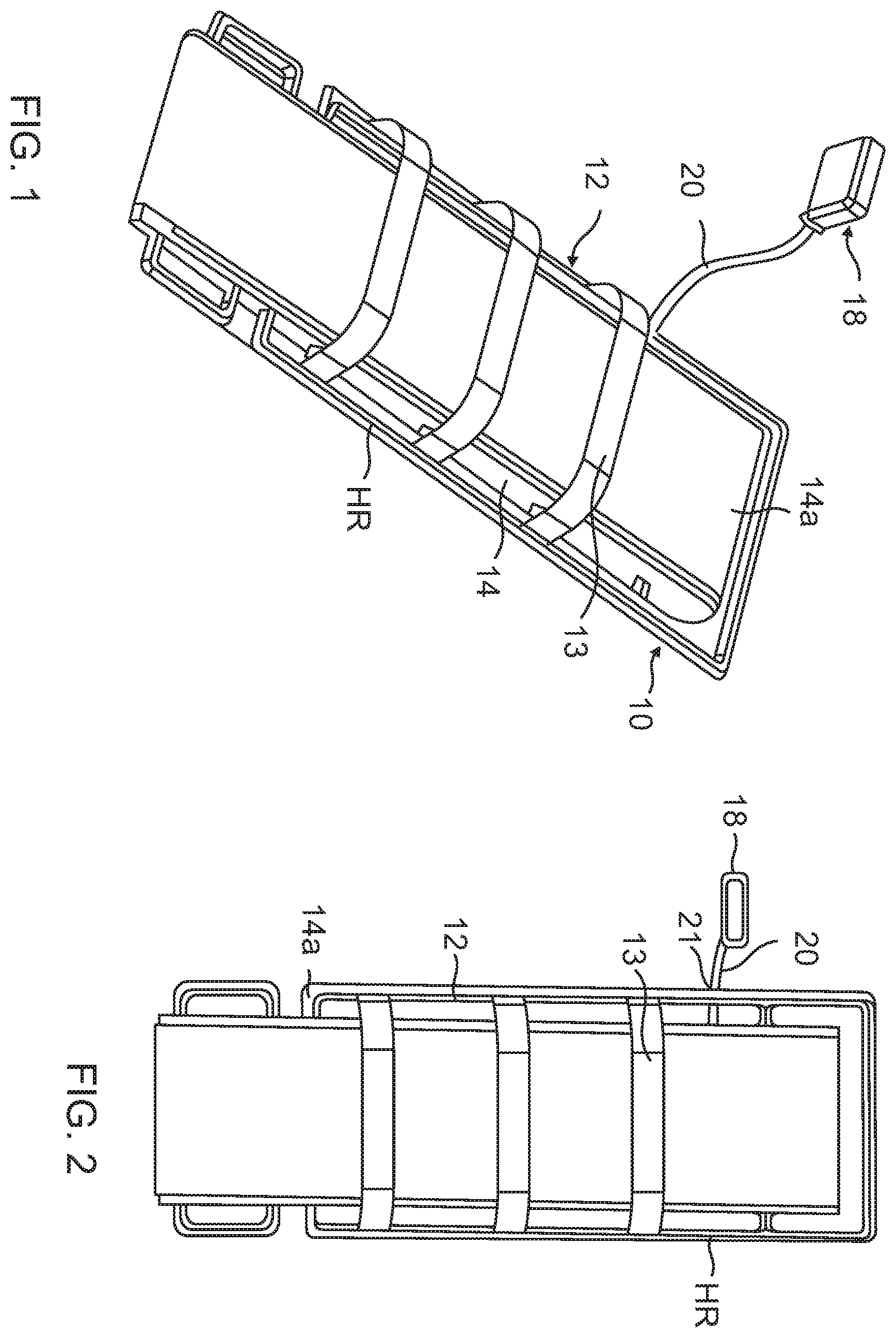
is a right-hand perspective view of one embodiment of our transport apparatus.
is a top plan view of the embodiment of our transport apparatus shown in .
is a left-hand perspective view of one embodiment of our transport apparatus shown in .
is a bottom perspective view of the embodiment of our transport apparatus shown in .
is a side view of the controller shown in connected to the drive system for rotating drive belts of our transport apparatus shown in .
is a perspective view of another embodiment of our apparatus.
A is an enlarged fragmentary view enclosed within the line 6 A of .
B is an enlarged, fragmentary, exploded side view of the controller aligned with and to be connected to an external portion of a drive axle the drive system.
C is an end view of the controller taken along line 6 C- 6 C of B .
D is an internal view of the apparatus' belt housing illustrating the drive system of our apparatus.
E is an enlarged, fragmentary, exploded side view of a manually operable crank aligned with and then connected to an external portion of a drive axle the drive system.
A is a perspective view of a third embodiment of our transport apparatus incorporating a safety device disabling the apparatus to avoid false starts. 17
B is a perspective view similar to A showing the safety device engaged to enable operation of our apparatus.
C is a fragmentary perspective view illustrating a D-ring in a down position; multiple switches in series connection to provide a circuit enabling the safety device of our transport apparatus shown in with all in down closed position.
D is a fragmentary perspective view similar to C illustrating the D-ring in an up position to open the circuit, disabling operation of our transport apparatus shown in A .
is an enlarged, fragmentary, perspective end portion view of the embodiment of our transport apparatus shown in A .
is a side view of the embodiment of our transport apparatus shown in A .
is a bottom view of the embodiment of our transport apparatus shown in .
A is a perspective bottom view of the embodiment of our transport apparatus shown in A .
B is an enlarged, fragmentary, bottom end portion view of the embodiment of our transport apparatus shown in A .
is schematic view illustrating our transport apparatus shown in being connected to the controller depicted in A .
is a perspective view of a fourth embodiment of our transport apparatus incorporating a locating device to avoid misplacing our apparatus and a smart technology diagnostic module that monitors patient.
is a perspective view of a drive pulley system for our transport apparatus shown in .
is a perspective view of a drive system for our transport apparatus shown in .
is a front side perspective view of an alternate embodiment of a controller that may be used with our transport apparatus.
is a rear perspective view of the controller shown in .
is a front perspective view of the controller shown in with its battery detached.
is rear perspective view of the controller shown in with its rear panel removed to exposed internal circuit components.
is schematic diagram of a controller connecter to the transport apparatus shown in A .
through 31 illustrate an embodiment of our transport apparatus having an adjustable alignment mechanism where:
is a perspective view of a back end of another embodiment of our transport apparatus with its exterior sides in place.
A is a fragmentary perspective view of the adjustment screw for changing belt tension.
is a perspective view of the transport apparatus shown in with the sides of its belt housing removed to expose its pulley-mounted belts of the apparatus' drive system.
is a perspective view of the transport apparatus shown in with housing components removed to show the tensioning and tracking system.
is a right-handed perspective view of the gearbox used in the transport apparatus shown in .
is a left-handed perspective view of the gearbox shown in .
is a perspective view of the forward end of the chain pulley side of the transport apparatus shown in with its sidewalls in place.
is a perspective view of the back end of the transport apparatus shown in similar to that of with its sidewalls removed.
is a perspective view of the side opposite the chain pulley side of the transport apparatus shown in with its sidewall removed.
is a perspective end view of a tracking adjustment mechanism used in the transport apparatus shown in .
is a perspective view of the forward end of the transport apparatus shown in including a tension adjustment mechanism used in the transport apparatus shown in 8 .
is a perspective view of a component of the tensioning and tracking mechanism used in the transport apparatus shown in .
DETAILED DESCRIPTION OF SOME ILLUSTRATIVE EMBODIMENTS
General
There are two embodiments of our apparatus illustrated: One apparatus is designated by the numeral 10 ( through 5 ) and the other apparatus by the numeral 10 a . Both apparatus 10 and 10 a are designed to transport a person from a position on the ground onto the apparatus generally in a horizontal orientation. Both apparatus 10 and 10 a comprise a generally rectangular board assembly 12 upon which the person is positioned. This board assembly 12 has predetermined dimensions sufficient to support this person in a horizontal orientation, for example, its width generally ranges from 16 to 28 inches, its length generally ranges from 70 to 84 inches, and its height generally ranges from 0.5 to 10 inches. The board assembly 12 also includes a chassis or belt housing 14 holding two endless belts 14 a and 14 b , a drive system DS within the housing, and an external battery B attached to a hand-held, manually portable, external, detachable controller. In the apparatus 10 this controller is designated by 26 the numeral 18 and in the apparatus 10 a its controller is designated by the numeral 18 a.
In the apparatus 10 a cable 20 connects the battery B to a motor M that is within the belt housing 14 . In the apparatus 10 a the cable is eliminated and a motor (not shown) is contained within its controller 18 a . The apparatus has a weight less than 100 pounds not including the weight of the detachable controller. The controller has a weight less than 12 pounds without the battery. The motor may be within a belt housing, or the motor may be within the controller. When the motor is within the controller, the weight of the apparatus is less than 65 pounds.
As depicted in through 33 , two endless belts 14 a and 14 b are coupled together mechanically to the motor M through a coupling connector CC on the motor's drive shaft to rotate the gears G 1 through G 4 ( ) in a gear box GB. The drive system DS is configured so that the endless belts 14 a and 14 b are advanced simultaneously in opposite directions. The battery B powers the motor M, which drives the gears G 1 through G 4 in the gear box GB. The drive system DS includes a tracking and tensioning system TTS for the belts 14 a and 14 b having spaced apart belt rollers BR 1 and BR 2 and spaced apart tension rollers TR 1 and TR 2 . In the embodiment depicted in through 6 E the motor (not shown) is within an enclosure 23 of the controller 18 a of the apparatus 10 a and is not within the belt housing 14 . This substantially reduces the weight of our apparatus. In either case, actuation of its drive motor advances the apparatus 10 or 10 a towards the person being transported.
As best shown in D , there are sprockets S 1 and S 2 respectively at the ends of the belt rollers BR 1 BR 2 mounted outboard along the exterior of the belt housing 14 . One portion of the chain pulley P 1 engages this sprocket S 1 and another portion of the chain pulley engages the gear G 4 so the chain pulley P 1 extends between them so that rotation of the gear G 4 causes the chain pulley P 1 to rotate clockwise or counter-clockwise depending on the position of the forward and reverse switch SW. Likewise, a portion of the chain pulley P 2 engages this sprocket S 2 and another portion of the chain pulley engages the gear G 3 so the chain pulley P 2 extends between them so that rotation of the gear G 3 causes the chain pulley P 2 to rotate clockwise or counter-clockwise depending on the position of the forward and reverse switch SW. Idler sprockets IS 1 and IS 2 are mounted to rotate freely and positioned outboard on the exterior of the belt housing 14 , respectively engaging intermediate portions of the chain pulleys P 1 and P 2 .
In the embodiment depicted in E , the motor in the controller 18 a may be operable but the battery B is “dead.” In this case a manually operated crank CR is used to actuate our apparatus' drive system DS by manually engaging an end E 3 of the crank with a detachable connector element in our transport apparatus and turning the crank.
Through 5
As best shown in , our apparatus 10 includes the board assembly 12 including the belt housing 14 , the drive system DS, and the detachable, manually portable controller 18 including the external battery B. The dimensions of the board assembly 12 are sufficient to support a typical adult person in a horizontal orientation when positioned on the board assembly 12 . For example, the maximum height of the board assembly 12 is 10 inches at the highest end, and its minimum height of 0.5 at the lowest end. Including any handrails HR the board assembly's length is generally from 70 to 84 inches, and its width is generally from 16 to 28 inches. A handrail HR attached to the opposed sides 14 facilitates lifting the apparatus 10 off the ground with the person thereon in a horizontal orientation. Straps 13 may be attached to the sides 14 or handrails HR for holding the person securely on the transport apparatus 10 .
As best illustrated in , the belt housing 14 at least partially encloses a pair of endless belts 14 a and 14 b . The belt 14 b is beneath the belt 14 a , and the person being transported is placed on the exposed top surface S of the belt 14 a when the transport apparatus 10 is placed on the ground in a horizontal orientation. A drive system DS for the rotating the endless belts 14 a and 14 b in opposite directions simultaneously is within the belt housing 14 , and it includes a battery powered motor M having a motor coupling MC that enables the motor to be connected to the external battery B in the detachable controller 18 via a flexible cable 20 .
The mechanical structure operably connects to the motor M and belts 14 a and 14 b so that, with the transport apparatus 10 on the ground and aligned with the person being transported, actuation of the motor advances the apparatus towards the person. The details of the mechanical structure for connecting the motor M to the drive system DS through a gear assembly GA ( ) within the belt housing 14 are disclosed in the '578 Patent. Upon actuation of the motor M, the belts 14 a and 14 b begin to rotate in opposite directions. The belt 14 b advances the transport apparatus 10 towards a person lying on the ground, with a portion of the belt 14 b continually engaging the ground to move the entire apparatus 10 towards the person. Concurrently, a forward portion of the belt 14 a engages the person and moves the person onto the exposed surface S of the belt 14 a.
The hand-held, portable, external, detachable controller 18 has a cable 20 extending outward from a compact, box-type housing 29 of the controller 18 with limited dimension. The cable 20 terminates in a cable coupling 21 and is configured to be manually connected and disconnected to the motor coupling MC. The dimensions of the housing 29 may be, for example, a height typically from 6 to 12 inches, a length typically from 6 to 8 inches, and a width typically from 4 to 6 inches. The housing 29 is configured to retain the battery B until manually removed. This housing 29 includes an internal compartment 18 b sized and shaped to hold the battery B. This housing 29 may have a water-tight compartment C with the battery B snugly seated within it. The battery B may have at least a portion extending therefrom, which a user may grasp and removed or insert through a door D in a side of the housing 29 , when opened manually, enables a user to replace the battery B as required. The housing 29 also includes a circuit board CB carrying external control circuits for the apparatus 10 , a manually actuated forward and reverse switch SW, and a slot SL configured to provide a handle H to allow a user to grasp the controller 18 and, with the cable 20 disconnected, carry the controller from place to place. A trigger T in the handle H is manually depressed to actuate the drive 11 system DS after activating the switch SW. In the reverse mode, a person on our apparatus 10 is unloaded from our apparatus.
Through 6 E
In the apparatus 10 a the cable 18 is eliminated, and instead its drive motor (not shown) is contained within its detachable controller 18 a . The battery B to power the motor is also within detachable controller 18 a . For example, the coupling connector CC mechanically connects the drive motor to an elongated gear shaft GS of the gear G 2 , rotating the drive gear G 2 . Extending from an axial end E 1 of the drive gear G 2 is a connector element, for example, in the form of an elongated gear shaft GS. At an outer end E 2 ( B ) of the coupling connector CC is a square shaped recess R creating a female cavity. To detachably connect the controller 18 a to the apparatus 10 a a detachable connector element is electrically coupled to the battery power motor in the controller 18 a . In this embodiment, an exposed, square shaped gear shaft GS of the gear G 2 functions as a connector element. The square shaped male axial end E 1 is manually inserted into the recess R upon the ends E 1 and E 2 engaging. The rectangular board assembly 12 of our transport apparatus 10 a has a weight of about 5 pounds less than the board assembly 12 of our transport apparatus 10 a because of the absence of a motor for the drive system. The coupling connector CC projects from the enclosure 23 of the controller 18 a and is axially aligned with the end E 1 of the shaft extending outward from the gear G 2 in this apparatus 10 a . The user manually seats the coupling connector CC on this end E 1 so this end is received within the recess R. Actuation of the motor rotates the gear G 2 , driving the endless belts 14 a and 14 b.
As illustrated in E , when the battery B is “dead” the manually operated crank CR is used to actuate the drive system DS. The end E 3 of the crank with a detachable connector element in our transport apparatus.
In this case a manually operated CR is used to actuate the drive system DS by manually engaging an end E 3 of the crank with the axial end E 1 of the elongated gear shaft GS is inserted into the square shaped recess R to detachably connect the controller 18 a to the apparatus 10 a . Rotation of the crank CR rotates the gear G 2 , manually driving the endless belts 14 a and 14 b.
Through 12
A third embodiment of our transport apparatus is generally designated by the alpha numeral 10 b in through 12 . This apparatus 10 b includes a safety device SD that prevents operation of the apparatus until the safety device is disabled. This safety device SD comprises a plurality of safety switches SS in series connection through an electric wire E. The individual safety switches SS are each individually connected to a D-ring DR mounted along the sides of the apparatus 10 b , for example, between the handrail FIR and the sides of the belt housing 14 . Each D-ring DR is manually moveable between a down position in C with the safety switch in series connection and an up position in D out of series connection. The switches DR 1 and DR 2 are up in A disabling operation of the apparatus 10 b . All the safety switches DR, including switches DR 1 and DR 2 , are down in B , enabling the operation of the apparatus 10 b . 22
Through 15
A fourth embodiment of our transport apparatus is generally designated by the alpha numeral 10 c in through 15 . This apparatus 10 c includes one or both of: a smart technology diagnostic module STDM that monitors a patient placed on the apparatus and a tracking device 25 that provides a signal for locating a misplaced one of the apparatus 10 c . The tracking device 25 is interactive with a mobile device such as an iPhone equipped with an application program for locating the tracking device. The smart technology diagnostic module STDM and the tracking device 25 may be enclosed within a housing for the motor.
also show an embodiment of our transport apparatus employing a drive pulley system PDS ( ) including a transmission gear system GRS ( ) enclosed within the belt housing 14 . Chain tensioners may also be employed so that chain drive pulleys P 1 and P 2 may be more closely synchronized as discussed in greater detail in connection with through 31 .
Through 20
One embodiment of a controller used in the transport apparatus 10 b of A is illustrated in through 20 and generally designated by the numeral 19 . This controller 19 has an open handle OH in its body B formed, for example, from a pair of molded plastic parts that, upon assembly, enclose a circuit board CB such as, for example, depicted in , which contains the circuits illustrated in the circuit diagram of including a motor controller MC. Portions of the on/off power switch PSW, trigger T, and forward and reverse switch SW protrude from the body so the user can access and manually actuate these switches as required when using the controller 19 .
As shown in , the transport apparatus 10 b is first connected to the controller 2 with a detachable rechargeable battery B electrically and mechanically connected to the circuit board CB. The on/off power switch PSW is first manually depressed to provide power and a light L is lit, indicating the controller 19 is activated. The user selects forward or reverse belt movement by actuating the forward and reverse switch SW. The transport apparatus 10 b is aligned with the person to be transported as discussed above, and the user actuates an off-lock button OLB in the open handle OH nearby the trigger T, allowing a user to depress this button with his or her thumb while depressing the trigger with his or her index finger.
Through 31
All conveyor-type belts need adjustment so that the belt remains centered and does not drift to the right or left as it moves along its path of travel. Belt tracking adjustment is different than belt tensioning adjustment, requiring separate mechanisms. In the embodiment of our transporting apparatus illustrated in through 31 and generally designated by the numeral 10 d , the back end FE of the belt housing 14 and adjoining planar sides are shaped into an enlarged nose configuration. The forward end is tapered into a narrow front edge. As depicted in , a flat, planar, pulley sidewall SW 1 and a flat, planar, non-pulley sidewall SW 2 of the belt housing 14 support between them belt rollers BR 1 and BR 2 for belt tracking and tension rollers TR 1 and TR 2 for belt tensioning. The respective shafts of the belt rollers BR 1 and BR 2 and tension rollers TR 1 and TR 2 are at a right angle to the planar sidewalls SW 1 and SW 2 . The belt pulley sidewall SW 1 and a non-pulley sidewall SW 2 are essentially of identically shaped, opposed, and parallel, being spaced apart a distance slightly greater than the width of the belts 14 a and 14 b that are of essentially the same width.
As the endless belts 14 a and 14 b advance along their respective upper and lower paths of travel, an adjustable alignment mechanism AAM ( ) maintains precisely these belts on their separate travel paths. It provides a fore-aft adjustment of the pulley shafts of +/−0.250 inch. This adjustability allows a user to easily and precisely square-up the drive pulleys P 1 and P 2 and account for normal manufacturing variation of the bends and punched mounting holes H in the belt housing 14 ( ). The belt rollers BR 1 and BR 2 and tension rollers TR 1 and TR 2 are at right angles to the sidewalls SW 1 or SW 2 . The belt rollers BR 1 and BR 2 are mounted directly to the sidewalls SW 1 or SW 2 . The tension rollers TR 1 and TR 2 are not mounted directly to the sidewalls SW 1 or SW 2 . Rather each one of a pair of tension roller adjustment mechanisms TAM 1 and TAM 2 are fixedly attached, respectively, to the inside surfaces of the sidewalls SW 1 and SW 2 . The tension rollers TR 1 and TR 2 engage the external surfaces of the belts 14 a and 14 b and apply a predetermined pressure against a portion of these external surfaces as the belts advance along their respective travel paths.
As depicted in , the pulley side of the transport apparatus 10 d has the chain pulleys P 1 and P 2 mounted in a manner that minimizes side-to-side travel of the belts 14 a and 14 b as these belts advance along their respective paths through the transport apparatus. The adjustment alignment mechanism AAM as best shown in includes a belt tensioning and tracking mechanism TTM ( ) that is mechanically coupled to and interactive with the apparatus' endless belts 14 a and 14 b . The endless belt 14 a is partially wrapped around the belt roller BR 1 that is mounted near the back end FE of the belt housing 14 to rotate and move this belt forward or reverse under the control of the forward and reverse switch SW. The 26 endless belt 14 b is also partially wrapped around the belt roller BR 2 that is mounted to the belt housing 14 to rotate and move this belt forward or reverse under the control of the forward and reverse switch SW. The belt rollers BR 1 and BR 2 and tension rollers TR 1 and TR 2 are all the same length equal to the distance between the sidewalls SW 1 and SW 2 . There are elevated flanges F ( ) at the opposed ends of the tension rollers TR 1 and TR 2 that engage the edges ED ( ) of the belts 14 a and 14 b . The opposed axial ends of the shafts of the belt rollers BR 1 and BR 2 are mounted in roller bearings to rotate either clockwise or counter-clockwise.
A pair of identically shaped opposed rigid mounting plates PT 1 , each one of the pair along the inside surfaces of the opposed sidewalls SW 1 and SW 2 , hold the shaft ends of the belt roller BR 1 at right angle to the sidewalls SW 1 and SW 2 . These rigid plates PT 1 and PT 2 each have a pair of easy access, spring-loaded adjustment mechanisms MY 1 and MY 2 that enable a user to manually readjust roller positions. Each of the mounting plates PT 1 are in fixed positions and each having an inside surfaces, and these surfaces face each other. Only the terminal end of the shaft of the belt roller BR 1 on the non-pulley side of our transport apparatus, and only this side, has the spring-loaded adjustment mechanism MY 1 attached to it. This adjustment mechanism MY 1 enables a user to move this terminal end of the belt roller BR 1 fore and aft. A rigid mounting plate PT 2 , also along the inside surface of the sidewall SW 1 , and rearward of the one plate PT 1 , holds the terminal shaft end of the belt roller BR 2 so that a user can manually move fore and aft the belt roller BR 2 . The belt roller BR 2 is at right angle to the sidewalls SW 1 and SW 2 and mounted in roller bearings. The mounting plate PT 2 is in a fixed positioned attached to the sidewall SW 1 .
The axles of the drive pulleys P 1 and P 2 are squared, flush and at right angles to the sidewalls SW 1 and SW 2 of the belt housing 14 . As little as 0.010 inch of misalignment on one side can cause a belt to drift to one side. Consequently, readjustment is required from time to time. Loosening the axle mounts and manually shifting them by a very small amount, under belt tension, is difficult and would be challenging to repeat during production. Using our adjustable alignment mechanism AAM, an easy to access screw mechanism, there are holes H ( ) in the sidewalls SW 1 and SW 2 to allow a user using a hex wrench to access and manually move yoke members Y 1 ( ) or Y 2 ( ), as the case may be, to readjust tension and tracking when required. As shown best in , the plates PT 1 and PT 2 are in fixed positions. The plate PT 1 is shaped to integrate with the forward end FE of the housing 14 , and it comprises a machined aluminum sheet that provides a solid end structure to resist impacts, and also eliminate any sharp edges where the belt housing 14 ends.
As shown best in , the adjustment mechanism MY 1 and adjustment mechanism MY 2 and tension roller adjustment mechanisms TAM 1 and TAM 2 , each have in the plate members PM having an elongated opening 01 in which a yoke Y that sides fore and aft within this opening. An adjustment screw AS having a head with eight detents (grooves) 19 a machined into it keeps the screw from turning on its own. There is a ball spring plunger BSP engaging the adjustment screw AS that upon rotating move the head to reposition the detents and generate a click sound, lock into the selected position. This results in approximately 0.007 inch of fore-aft pulley shaft movement (tightening or loosening), per click (⅛ turn of the screw). In order to adjust belt tracking, the adjustment screw AS is the only thing that needs to be touched. No other screws will need to be loosened or tightened. The adjustment screw AS does not need a jam nut or lock nut because the spring-loaded plunger keeps the screw from turning in either direction.
Belt tension adjustment relies on moving the position of the tension rollers TR 1 and TR 2 . The main purpose of the tension rollers TR 1 and TR 2 is to increase the amount that the belt wraps around the drive pulley in order to improve belt-to-pulley traction. In our case, we are using the tension rollers TR 1 and TR as belt tension adjusters too. Note that the tension rollers TR 1 and TR 2 have flanges F to help to center the belts. Most of the belt tracking must be taken care of by using the tracking adjusters as described earlier. These flanges F will quickly wear out a belt along its edges if the belt tracking is significantly off. Like the tension roller adjustment mechanisms TAM 1 and TAM 2 discussed above, adjustment of the belt tension is made by simply turning the adjustment screw AS using a hex wrench. No other screws need to be loosened or tightened. Because the adjusters are buried deep into the crowded belt housing four 1.375 inch diameter access holes in the side of the belt housing 14 allow for adjustment of the belt tension. These holes will allow an inch drive ratchet wrench to enter for quick tension adjustments. The access holes will be plugged with semi-permanent plastic caps. 18
Scope of the Invention
The above presents a description of the best mode we contemplate of carrying out our apparatus for transport a person and method, and of the manner and process of making and using them, in such full, clear, concise, and exact terms as to enable a person skilled in the art to make and use. Our apparatus for transport a person and method is, however, susceptible to modifications and alternate constructions from the illustrative embodiment discussed above which are fully equivalent. Consequently, it is not the intention to limit our apparatus for transport a person and method to the particular embodiment disclosed. On the contrary, our intention is to cover all modifications and alternate constructions coming within the spirit and scope of our apparatus for transport a person and method as generally expressed by the following claims, which particularly point out and distinctly claim the subject matter of my our invention.
Figures (20)
Citations
This patent cites (26)
- US2397092
- US6486792
- US6910677
- US6981745
- US7047578
- US7200881
- US2001/0013437
- US2003/0009115
- US2003/0106153
- US2004/0244108
- US2007/0056095
- US2009/0000035
- US2009/0107773
- US2010/0146704
- US2010/0178981
- US2011/0218384
- US2012/0304386
- US2014/0373273
- US2016/0158082
- US2017/0266069
- US2017/0340498
- US2018/0021191
- US2021/0121342
- US2619335
- US202013102928
- US2016029507