Abstract
A wheel including a substrate, a driving assembly, a fixing bracket, and a damper is provided. The driving assembly is disposed on the substrate to drive the substrate to rotate. The driving assembly and the damper are fixed onto the fixing bracket. The damper is disposed between the driving assembly and the fixing bracket, and the driving assembly is located between the substrate and the damper. The driving assembly has a first diameter, the damper has a second diameter, and the second diameter is greater than or equal to the first diameter. The wheel is disposed in a projector and may effectively reduce vibration and noise generated during the operation of the wheel, so as to mitigate a noise problem of the projector and increase a service life of the wheel.
Claims (17)
1 . A wheel, comprising: a substrate, a driving assembly, a fixing bracket, and a damper, wherein the damper is disk-shaped; the driving assembly is disposed on the substrate and is configured to drive the substrate to rotate; the driving assembly and the damper are fixed onto the fixing bracket, wherein the damper is disposed between the driving assembly and the fixing bracket, and the driving assembly is located between the substrate and the damper; the driving assembly has a plurality of first thread holes, the damper has a plurality of second thread holes, and the plurality of first thread holes respectively correspond to the plurality of second thread holes; and the driving assembly has a first diameter, the damper has a second diameter, and the second diameter is greater than or equal to the first diameter.
5 . A wheel, comprising: a substrate, a driving assembly, a fixing bracket, and a damper, wherein a shape of the damper is a continuous ring shape or a discontinuous ring shape; the driving assembly is disposed on the substrate and is configured to drive the substrate to rotate; the driving assembly and the damper are fixed onto the fixing bracket, wherein the damper is disposed between the driving assembly and the fixing bracket, and the driving assembly is located between the substrate and the damper; the driving assembly has a first diameter, the damper has a second diameter, and the second diameter is greater than or equal to the first diameter; and wherein the driving assembly has a plurality of thread holes and a center point, a longest distance and a shortest distance between an edge of each of the plurality of first thread holes and the center point are defined, the damper has an inner diameter and an outer diameter, the second diameter is the outer diameter, the inner diameter is greater than or equal to the shortest distance, and the outer diameter is greater than or equal to the longest distance.
11 . A wheel, comprising: a substrate, a driving assembly, a fixing bracket, and a damper, wherein a shape of the damper is a continuous ring shape or a discontinuous ring shape; the driving assembly is disposed on the substrate and is configured to drive the substrate to rotate; the driving assembly and the damper are fixed onto the fixing bracket, wherein the damper is disposed between the driving assembly and the fixing bracket, and the driving assembly is located between the substrate and the damper; the driving assembly has a first diameter, the damper has a second diameter, and the second diameter is greater than or equal to the first diameter; and wherein the driving assembly comprises a first portion and a second portion, the first portion has a first bearing surface, the second portion has a second bearing surface, the damper comprises a first damper and a second damper, the first damper has a first inner diameter and a first outer diameter, the second damper has a second inner diameter and a second outer diameter, the second diameter is the second outer diameter, the second inner diameter is greater than or equal to the first outer diameter, the first damper contacts the first bearing surface, and the second damper contacts the second bearing surface.
Show 14 dependent claims
2 . The wheel as claimed in claim 1 , further comprising: a heat dissipation module, fixed onto the driving assembly, wherein the damper is located between the heat dissipation module and the fixing bracket.
3 . The wheel as claimed in claim 2 , wherein the heat dissipation module comprises a support plate, the support plate has a plurality of third thread holes, and the plurality of first thread holes, the plurality of second thread holes, and the plurality of third thread holes are correspondingly arranged, respectively.
4 . The wheel as claimed in claim 3 , wherein the heat dissipation module further comprises a heat sink group, the wheel is disposed in a cavity of a light combining module, and the heat sink group is located in the cavity or extends outside the cavity.
6 . The wheel as claimed in claim 5 , wherein a thickness of the damper has a constant value.
7 . The wheel as claimed in claim 6 , wherein a first contact surface of the driving assembly and the damper is parallel to a second contact surface of the damper and the fixing bracket.
8 . The wheel as claimed in claim 5 , further comprising: a heat dissipation module, fixed onto the driving assembly, wherein the damper is located between the heat dissipation module and the fixing bracket.
9 . The wheel as claimed in claim 8 , wherein the heat dissipation module comprises a support plate, the support plate has a plurality of first thread holes, the fixing bracket has a plurality of second thread holes, and the plurality of first thread holes respectively correspond to the plurality of second thread holes.
10 . The wheel as claimed in claim 9 , wherein the heat dissipation module further comprises a heat sink group, the wheel is disposed in a cavity of a light combining module, and the heat sink group is located in the cavity or extends outside the cavity.
12 . The wheel as claimed in claim 11 , wherein the first damper and the second damper are independent or connected as a whole.
13 . The wheel as claimed in claim 11 , wherein the first portion of the driving assembly has a plurality of thread holes and a center point, a longest distance and a shortest distance between an edge of each of the plurality of thread holes and the center point are defined, the first inner diameter is greater than or equal to the shortest distance, and the first outer diameter is greater than or equal to the longest distance.
14 . The wheel as claimed in claim 11 , wherein the first bearing surface of the first portion is a circular plane, the second bearing surface of the second portion has a ring shape, the second inner diameter is greater than or equal to a diameter of the first bearing surface, the second outer diameter is greater than or equal to a diameter of the second bearing surface, and the first diameter is the diameter of the second bearing surface.
15 . The wheel as claimed in claim 14 , wherein a thickness of the first damper has a constant value.
16 . The wheel as claimed in claim 15 , wherein the first portion of the driving assembly has a first thickness, the first damper has a second thickness, the second damper has a third thickness, the fixing bracket comprises a main body portion and a bearing portion connected to the main body portion, the bearing portion has a fourth thickness, and a sum of the first thickness and the second thickness is equal to a sum of the third thickness and the fourth thickness.
17 . The wheel as claimed in claim 11 , wherein the first damper and the second damper are seamlessly connected.
Full Description
Show full text →
CROSS-REFERENCE TO RELATED APPLICATION
This application claims the priority benefit of U.S. provisional application Ser. No. 63/174,521, filed on Apr. 13, 2021 and China application serial no. 202121268909.7, filed on Jun. 8, 2021. The entirety of each of the above-mentioned patent applications is hereby incorporated by reference herein and made a part of this specification.
BACKGROUND
Technical Field
The invention relates to a wheel, and particularly relates to a wheel capable of effectively reducing vibration and noise generated during operation and reducing a temperature.
Description of Related Art
A wheel is one of important components of a projector, which is, for example, a phosphor wheel, a color filter wheel, a diffusing wheel, or the like. Regardless of the type of the wheel, during a rotation process, as a weight and a speed of the wheel increase, vibration is inevitably induced, and temperature of the wheel is raised. The vibration of the wheel includes axial vibration along a rotation axis and radial vibration along a direction of a rotating centrifugal force. The vibration of the wheel may be transmitted to other positions in the projector through mechanical components, which causes other mechanical components to produce noise, thereby causing a noise problem of the projector. In order to reduce a transmission amount of the vibration of the wheel, a weight of a wheel bracket may be increased. However, as a rotation speed of the wheel increases, the weight of the wheel bracket also needs to increase, which leads to an increase in a weight and a volume of the projector.
In addition, as the weight and heat of the wheel increase, a temperature of a driving assembly (a motor) is also increased. In order to reduce the temperature of the driving assembly, a fan is generally used to lower down the temperature of the driving assembly. When the temperature of the driving assembly rises significantly, a fan with a relatively large flow rate must be applied, which result in the increase in the noise and the volume of the projector.
The information disclosed in this Background section is only for enhancement of understanding of the background of the described technology and therefore it may contain information that does not form the prior art that is already known to a person of ordinary skill in the art. Further, the information disclosed in the Background section does not mean that one or more problems to be resolved by one or more embodiments of the invention was acknowledged by a person of ordinary skill in the art.
SUMMARY
The invention is directed to a wheel, which is adapted to effectively reduce vibration and noise generated during an operation of the wheel, thereby mitigating a noise problem of a projector and increasing a service life of the wheel.
In order to achieve one or a portion of or all of the objects or other objects, an embodiment of the invention provides a wheel including a substrate, a driving assembly, a fixing bracket and a damper. The driving assembly is disposed on the substrate to drive the substrate to rotate. The driving assembly and the damper are fixed onto the fixing bracket. The damper is disposed between the driving assembly and the fixing bracket, and the driving assembly is located between the substrate and the damper. The driving assembly has a first diameter, the damper has a second diameter, and the second diameter is greater than or equal to the first diameter.
Based on the above description, one or more embodiments of the invention have at least one of following advantages or effects. In the design of the wheel provided in one or more embodiments of the invention, the driving assembly and the damper are fixed onto the fixing bracket, and the damper is disposed between the driving assembly and the fixing bracket to reduce an amount of vibration transmitted to the fixing bracket, so as to effectively reduce the noise of the wheel during operation, mitigate an overall noise problem of the projector, and increase the service life of the wheel.
Other objectives, features and advantages of the present invention will be further understood from the further technological features disclosed by the embodiments of the present invention wherein there are shown and described preferred embodiments of this invention, simply by way of illustration of modes best suited to carry out the invention.
BRIEF DESCRIPTION OF THE DRAWINGS
The accompanying drawings are included to provide a further understanding of the invention, and are incorporated in and constitute a part of this specification. The drawings illustrate embodiments of the invention and, together with the description, serve to explain the principles of the invention.
A is a schematic three-dimensional view of a wheel according to an embodiment of the invention.
B is a schematic three-dimensional exploded view of the wheel of A .
C is a schematic three-dimensional exploded view of the wheel of A from another perspective.
D is a schematic cross-sectional view of the wheel of A .
A is a schematic three-dimensional exploded view of a wheel according to another embodiment of the invention.
B is a schematic three-dimensional exploded view of the wheel of A from another perspective.
C is a schematic cross-sectional view of the wheel of A .
A is a schematic three-dimensional view of a wheel according to another embodiment of the invention.
B is a schematic three-dimensional exploded view of the wheel of A .
C is a schematic three-dimensional exploded view of the wheel of A from another perspective.
D is a schematic cross-sectional view of the wheel of A .
E is a schematic cross-sectional view of a wheel according to another embodiment of the invention.
A is a schematic three-dimensional view of a wheel according to another embodiment of the invention.
B is a schematic three-dimensional exploded view of the wheel of A .
C is a schematic three-dimensional exploded view of the wheel of A from another perspective.
D is a schematic cross-sectional view of the wheel of A .
DESCRIPTION OF THE EMBODIMENTS
In the following detailed description of the preferred embodiments, reference is made to the accompanying drawings which form a part hereof, and in which are shown by way of illustration specific embodiments in which the invention may be practiced. In this regard, directional terminology, such as “top,” “bottom,” “front,” “back,” etc., is used with reference to the orientation of the Figure(s) being described. The components of the present invention can be positioned in a number of different orientations. As such, the directional terminology is used for purposes of illustration and is in no way limiting. On the other hand, the drawings are only schematic and the sizes of components may be exaggerated for clarity. It is to be understood that other embodiments may be utilized and structural changes may be made without departing from the scope of the present invention. Also, it is to be understood that the phraseology and terminology used herein are for the purpose of description and should not be regarded as limiting. The use of “including,” “comprising,” or “having” and variations thereof herein is meant to encompass the items listed thereafter and equivalents thereof as well as additional items. Unless limited otherwise, the terms “connected,” “coupled,” and “mounted” and variations thereof herein are used broadly and encompass direct and indirect connections, couplings, and mountings. Similarly, the terms “facing,” “faces” and variations thereof herein are used broadly and encompass direct and indirect facing, and “adjacent to” and variations thereof herein are used broadly and encompass directly and indirectly “adjacent to”. Therefore, the description of “A” component facing “B” component herein may contain the situations that “A” component directly faces “B” component or one or more additional components are between “A” component and “B” component. Also, the description of “A” component “adjacent to” “B” component herein may contain the situations that “A” component is directly “adjacent to” “B” component or one or more additional components are between “A” component and “B” component. Accordingly, the drawings and descriptions will be regarded as illustrative in nature and not as restrictive.
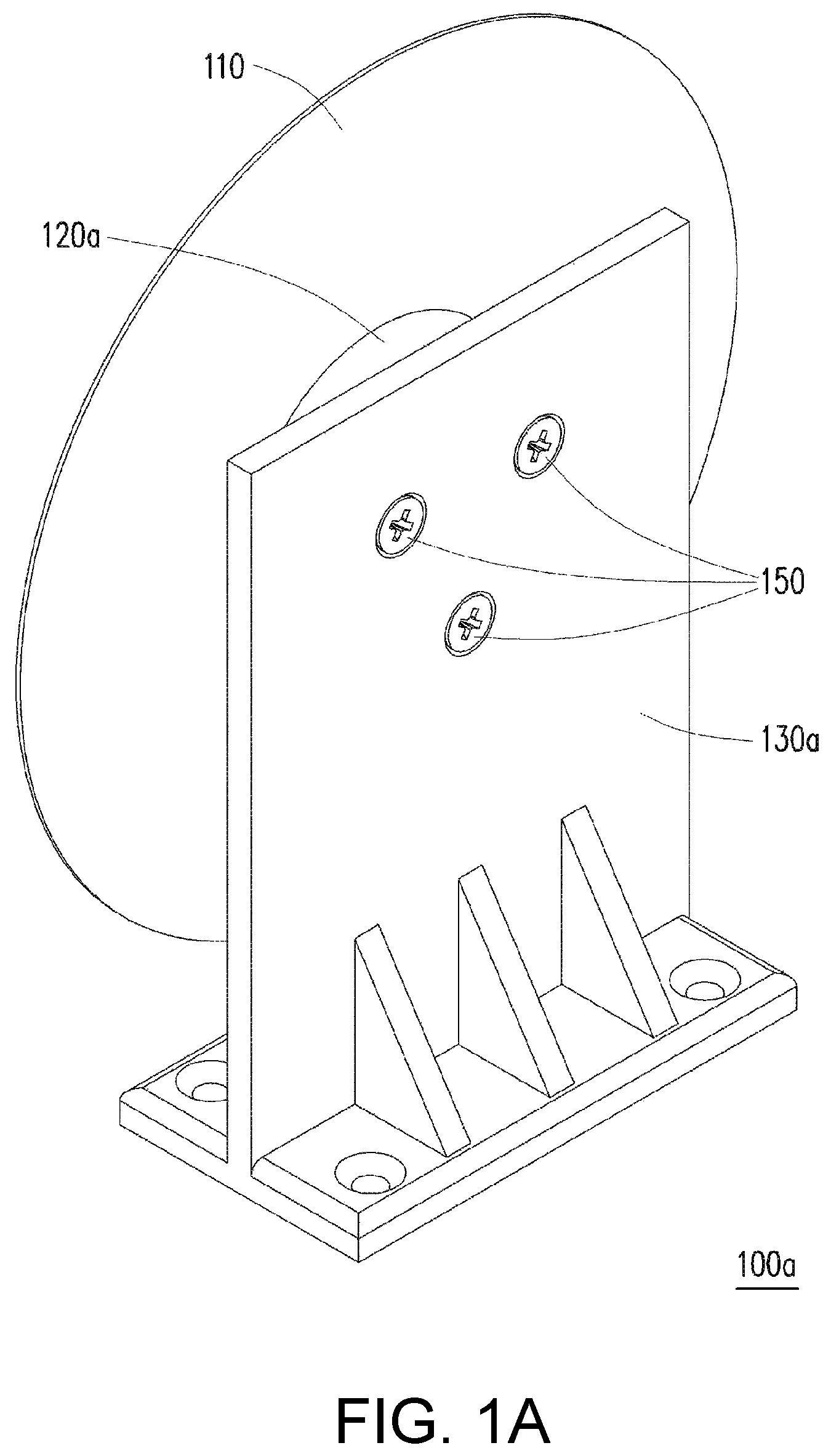
A is a schematic three-dimensional view of a wheel according to an embodiment of the invention. B is a schematic three-dimensional exploded view of the wheel of A . C is a schematic three-dimensional exploded view of the wheel of A from another perspective. D is a schematic cross-sectional view of the wheel of A . Referring to A , B , and C at the same time, in the embodiment, a wheel 100 a includes a substrate 110 , a driving assembly 120 a , a fixing bracket 130 a , and a damper 140 a . The driving assembly 120 a is disposed on the substrate 110 to drive the substrate 110 to rotate. The wheel 100 a is arranged in a projector (not shown), and the fixing bracket 130 a of the wheel 100 a is fixed in the projector. The driving assembly 120 a and the damper 140 a are fixed onto the fixing bracket 130 a . The damper 140 a is disposed between the driving assembly 120 a and the fixing bracket 130 a , and the driving assembly 120 a is located between the substrate 110 and the damper 140 a . Specifically, an orthographic projection of the damper 140 a on the substrate 110 overlaps with an orthographic projection of the driving assembly 120 a on the substrate 110 . The driving assembly 120 a has a first diameter D 1 , and the damper 140 a has a second diameter D 2 , and the second diameter D 2 is greater than or equal to the first diameter D 1 .
In detail, in the embodiment, the substrate 110 is, for example, a phosphor wheel substrate, a filter color wheel substrate, or a diffusion wheel substrate, but the invention is not limited thereto. The driving assembly 120 a is, for example, a motor, and the driving assembly 120 a has a plurality of first thread holes 122 a . A material of the damper 140 a is, for example, rubber or non-metallic materials, such as mylar, polycarbonate (PC), polyvinyl chloride (PVC), or polystyrene (PS), or timber, thereby reducing an amount of vibration transmitted to the fixing bracket 130 a , and mitigating the noise problem generated by the wheel in the projector. In addition, the damper 140 a of the embodiment has a plurality of second thread holes 142 a , where the second thread holes 142 a respectively correspond to the first thread holes 122 a of the driving assembly 120 a . Moreover, the fixing bracket 130 a of the embodiment has a plurality of thread holes 132 a , where the thread holes 132 a respectively correspond to the second thread holes 142 a of the damper 140 a and the first thread holes 122 a of the driving assembly 120 a.
Referring to A , B , C and D at the same time, the wheel 100 a of the embodiment further includes a plurality of locking members 150 , where the locking members 150 sequentially pass through the thread holes 132 a , the second thread holes 142 a , and the first thread holes 122 a to fix the driving assembly 120 a disposed on the substrate 110 and the damper 140 a onto the fixing bracket 130 a . Here, the locking members 150 are, for example, screws or bolts, but the invention is not limited thereto. In particular, in the embodiment, a thickness of the damper 140 a has a constant value, i.e., a uniform thickness, and a shape of the damper 140 a is embodied as a circle disk, but the invention is not limited thereto.
In brief, in the design of the wheel 100 a of the embodiment, the driving assembly 120 a and the damper 140 a are fixed onto the fixing bracket 130 a , where the damper 140 a is disposed between the driving assembly 120 a and the fixing bracket 130 a , thereby reducing the amount of vibration transmitted to the fixing bracket 130 a to effectively reduce the noise generated during the operation of the wheel 100 a , and mitigate the overall noise of the projector and increase a service life of the wheel 100 a.
It should be noticed that reference numbers of the components and a part of contents of the aforementioned embodiment are also used in the following embodiment, where the same reference numbers denote the same or like components, and descriptions of the same technical contents are omitted. The aforementioned embodiment may be referred for descriptions of the omitted parts, and detailed descriptions thereof are not repeated in the following embodiment.
A is a schematic three-dimensional exploded view of a wheel according to another embodiment of the invention. B is a schematic three-dimensional exploded view of the wheel of A from another perspective. C is a schematic cross-sectional view of the wheel of A . Referring to B and A at the same time, a wheel 100 b of the embodiment is similar to the wheel 100 a of B , and a difference therebetween is that in the embodiment, a shape of a damper 140 b of the wheel 100 b is embodied as a ring shape, for example, a continuous ring shape, but the invention is not limited thereto. In another embodiment, the shape of the damper 140 b may also be a discontinuous ring shape, which still belongs to the scope of the invention. In brief, the damper 140 b may be an integral type or a segmental type ring-shape design according to actual requirements.
In detail, referring to A , B and C , the damper 140 b has a plurality of second thread holes 142 b , where the first thread hole 122 a of the driving assembly 120 a , the second thread hole 142 b of the damper 140 b , and the thread hole 132 a of the fixing bracket 130 a are correspondingly arranged. The locking members 150 pass through the thread holes 132 a , the second thread holes 142 b , and the first thread holes 122 a in sequence to fix the driving assembly 120 a on the substrate 110 and the damper 140 b onto the fixing bracket 130 a . Here, the driving assembly 120 a has a center point C, where a longest distance R 1 and a shortest distance R 2 between an edge of each first thread hole 122 a and the center point C are defined. The damper 140 b has an inner diameter D 3 and an outer diameter D 2 ′ (i.e., a second diameter). In particular, the inner diameter D 3 of the damper 140 b is preferably greater than or equal to the shortest distance R 2 , and the outer diameter D 2 ′ of the damper 140 b is preferably greater than or equal to the longest distance R 1 . In addition, as shown in C , a first contact surface S 1 of the driving assembly 120 a and the damper 140 b of the embodiment is parallel to a second contact surface S 2 of the damper 140 b and the fixing bracket 130 a.
A is a schematic three-dimensional view of a wheel according to another embodiment of the invention. B is a schematic three-dimensional exploded view of the wheel of A . C is a schematic three-dimensional exploded view of the wheel of A from another perspective. D is a schematic cross-sectional view of the wheel of A . E is a schematic cross-sectional view of a wheel according to another embodiment of the invention. Referring to A , B , C , A , B , and C at the same time, in the embodiment, a wheel 100 c in A is similar to the wheel 100 a in A , and a difference therebetween is that in the embodiment, structures of a driving assembly 120 c and a damper 140 c in A are different from the structures of the driving assembly 120 a and the damper 140 a in A .
In detail, in the embodiment, the driving assembly 120 c includes a first portion 125 and a second portion 127 connected to each other, where the first portion 125 has a first bearing surface S 3 , and the second portion 127 has a second bearing surface S 4 . Moreover, the damper 140 c of the embodiment includes a first damper 145 c and a second damper 147 c , where the first damper 145 c and the second damper 147 c are embodied in ring shapes, and are, for example, continuous ring shapes. Furthermore, the first damper 145 c has a first inner diameter D 4 and a first outer diameter D 5 . The second damper 147 c has a second inner diameter D 6 and a second outer diameter D 7 (i.e., a second diameter), where the second inner diameter D 6 is greater than or equal to the first outer diameter D 5 . Here, the first damper 145 c and the second damper 147 c are connected as a whole, i.e., the first damper 145 c and the second damper 147 c are seamlessly connected and integrally formed. Certainly, in other embodiments, the first damper 145 c and the second damper 147 c may also be independent, i.e., two pieces.
Referring to B and C , the first portion 125 of the driving assembly 120 c of the embodiment has a plurality of first thread holes 122 c and a center point C. A longest distance R 3 and a shortest distance R 4 between an edge of each first thread hole 122 c and the center point C are defined. The first inner diameter D 4 of the first damper 145 c is greater than or equal to the shortest distance R 4 , and the first outer diameter D 5 of the first damper 145 c is greater than or equal to the longest distance R 3 . Furthermore, a shape of the first bearing surface S 3 of the first portion 125 of the driving assembly 120 c is embodied as a circular plane, and the second inner diameter D 6 of the second damper 147 c is greater than or equal to a diameter D 8 of the first bearing surface S 3 . The second bearing surface S 4 of the second portion 127 of the driving assembly 120 c is embodied in a ring shape, and the second outer diameter D 7 of the second damper 147 c is greater than or equal to a diameter D 9 (i.e., a first diameter) of the second bearing surface S 4 .
Referring to D , in the embodiment, the distances between the first bearing surface S 3 and the second bearing surface S 4 to the fixing bracket 130 a are different, the first damper 145 c contacts the first bearing surface S 3 , and the second damper 147 c contacts the second bearing surface S 4 . A thickness of the first damper 145 c has a constant value, i.e., a uniform thickness. The first portion 125 of the driving assembly 120 c has a first thickness T 1 , the first damper 145 c has a second thickness T 2 , and the second damper 147 c has a third thickness T 3 . The third thickness T 3 is equal to the sum of the first thickness T 1 and the second thickness T 2 . The first damper 145 c and the second damper 147 c are seamlessly connected, and the first damper 145 c and the second damper 147 c only differ in thickness. The locking members 150 pass through the thread holes 132 a , the second thread holes 142 c , and the first thread holes 122 c in sequence to fix the driving assembly 120 c disposed on the substrate 110 and the damper 140 c onto the fixing bracket 130 a.
In another embodiment, referring to E , a fixing bracket 130 d of a wheel 100 d includes a main body portion 135 and a bearing portion 137 connected to the main body portion 135 . Distances between the first bearing surface S 3 and the second bearing surface S 4 and the fixing bracket 130 d of the embodiment are different. A first damper 145 d contacts the first bearing surface S 3 , and a second damper 147 d contacts the second bearing surface S 4 . The first portion 125 of the driving assembly 120 c has a first thickness T 1 , the first damper 145 d of the damper 140 d has a second thickness T 2 ′, the second damper 147 d of the damper 140 d has a third thickness T 3 ′, and the bearing portion 137 of the fixing bracket 130 d has a fourth thickness T 4 . The sum of the first thickness T 1 and the second thickness T 2 ′ is equal to the sum of the third thickness T 3 ′ and the fourth thickness T 4 . Where, a magnitude of the third thickness T 3 ′ depends on the fourth thickness T 4 of the bearing portion 137 connected to the main body portion 135 in the fixing bracket 130 d , and the third thickness T 3 ′ is greater than zero. In other words, if the fourth thickness T 4 is equal to zero, similar to that shown in D , the first damper 145 d and the second damper 147 d are seamlessly connected, and the first damper 145 d and the second damper 147 d only differ in thickness, and the third thickness T 3 ′ is equal to the sum of the first thickness T 1 and the second thickness T 2 ′. The locking members 150 sequentially pass through the thread holes 132 d , the second thread holes 142 d and the first thread holes 122 c to fix the driving assembly 120 c disposed on the substrate 110 and the damper 140 d onto the fixing bracket 130 d.
In brief, since the driving assembly 120 c of the embodiment is composed of the first portion 125 and the second portion 127 , the distances from the fixing brackets 130 a , 130 d to the first bearing surface S 3 and the second bearing surface S 4 are different, so that the structures and thicknesses of the dampers 140 c and 140 d are also different accordingly. Namely, the structural design of the dampers 140 c , 140 d may be changed according to a shape of the driving assembly 120 c or the fixing bracket 130 a , 130 d . In the embodiment, the first dampers 145 c , 145 d of the dampers 140 c , 140 d are not overlapped with the second dampers 147 c , 147 d , but may be connected as one damper 140 c (as shown in D ). The second thicknesses T 2 , T 2 ′ of the first dampers 145 c , 145 d and the third thicknesses T 3 , T 3 ′ of the second damper 147 c , 147 d do not need to be the same and are both greater than zero. In addition, the first dampers 145 c , 145 d and the second dampers 147 c , 147 d may be an integral type ring-shape design or a segmental type ring-shape design, which is not limited by the invention.
A is a schematic three-dimensional view of a wheel according to another embodiment of the invention. B is a schematic three-dimensional exploded view of the wheel of A . C is a schematic three-dimensional exploded view of the wheel of A from another perspective. D is a schematic cross-sectional view of the wheel of A . E is a schematic cross-sectional view of a wheel according to another embodiment of the invention. Referring to A and A at the same time, in the embodiment, a wheel 100 e of A is similar to the wheel 100 a of A , and a difference therebetween is that in the embodiment, the wheel 100 e also includes a heat dissipation module 160 e , which is fixed onto the driving assembly 120 a.
In detail, referring to A , B , C and D at the same time, in the embodiment, the damper 140 a is located between the heat dissipation module 160 e and the fixing bracket 130 a . The heat dissipation module 160 e includes a support plate 165 e and a heat sink group 167 e connected to the support plate 165 e . The support plate 165 e has a plurality of third thread holes 162 e , and the first thread holes 122 a of the driving assembly 120 a , the second thread holes 142 a of the damper 140 a , the thread holes 132 a of the fixing bracket 130 a and the third thread holes 162 e of the support plate 165 e are correspondingly arranged, respectively. The locking members 150 pass through the thread holes 132 a , the second thread holes 142 a , the third thread holes 162 e , and the first thread holes 122 a in sequence to fix the driving assembly 120 a disposed on the substrate 110 , the support plate 165 e of the heat dissipation module 160 e , and the damper 140 a onto the fixing bracket 130 a . The wheel 100 e is disposed in a cavity E of a light combining module M (shown in D ), where the heat sink group 167 e of the heat dissipation module 160 e is located in the cavity E, which does not affect a component layout of the projector.
In another embodiment, referring to D and 4 E at the same time, in the embodiment, the wheel 100 e of D is similar to a wheel 100 f of E , and a difference therebetween is that in the embodiment, a heat sink group 167 f of the heat dissipation module 160 f of the wheel 100 f of E extends outside the cavity E. In this way, a heat dissipation path of the driving assembly 120 a may be increased to achieve an effect of reducing a temperature of the driving assembly 120 a . The locking members 150 pass through the thread holes 132 a , the second thread holes 142 a , the third thread holes 162 f , and the first thread holes 122 a in sequence to fix the driving assembly 120 a disposed on the substrate 110 , the support plate 165 f of the heat dissipation module 160 f , and the damper 140 a onto the fixing bracket 130 a.
In brief, through the arrangement of the heat dissipation modules 160 e and 160 f , the heat generated by the driving assembly 120 a may be dissipated through the heat dissipation modules 160 e and 160 f , so as to achieve the purpose of reducing the temperature of the driving assembly 120 a.
A is a schematic three-dimensional view of a wheel according to another embodiment of the invention. B is a schematic three-dimensional exploded view of the wheel of A . C is a schematic three-dimensional exploded view of the wheel of A from another perspective. D is a schematic cross-sectional view of the wheel of A . Referring to A , B , A and B at the same time, a wheel 100 g of A of the embodiment is similar to the wheel 100 e of A , and a difference therebetween is that in the embodiment, a shape of a damper 140 g in B is a quadrangle, i.e., not a disk, and the arrangement of second thread holes 132 g of a fixing bracket 130 g does not correspond to the arrangement of the first thread holes 122 a of the driving assembly 120 a.
In detail, referring to B , C and D at the same time, in the embodiment, a heat dissipation module 160 g includes a support plate 165 g and a heat sink group 167 g connected to the support plate 165 g . The third thread holes 162 g of the support plate 165 g respectively correspond to the first thread holes 122 a of the driving assembly 120 a , where locking members 155 pass through the third thread holes 162 g and the first thread holes 122 a in sequence to fix the driving assembly 120 a disposed on the substrate 110 onto the heat dissipation module 160 g . Moreover, the support plate 165 g of the embodiment further has a plurality of first thread holes 164 g , the fixing bracket 130 g has a plurality of second thread holes 132 g , and the damper 140 g has a plurality of thread holes 142 g , where the second thread holes 132 g , the thread holes 142 g and the first thread holes 164 g are correspondingly arranged, respectively. The locking members 150 pass through the second thread holes 132 g , the thread holes 142 g , and the first thread holes 164 g in sequence to fix the support plate 165 g of the heat dissipation module 160 g and the driving assembly 120 a locked thereon and the damper 140 g onto the fixing bracket 130 g.
In brief, the third thread holes 162 g and the first thread holes 164 g of the heat dissipation module 160 g of the embodiment are located at different positions, for example, as shown in B , the first thread holes 164 g are located outside the third thread holes 162 g and the first thread holes 164 g surround the third thread holes 162 g , so that the heat dissipation module 160 g may be respectively locked with the driving assembly 120 a and the fixing bracket 130 g , which may reduce the amount of vibration transmitted from the driving assembly 120 a to the fixing bracket 130 g , thereby reducing the noise generated by the driving assembly 120 a . In addition, since the shape of the damper 140 g of the embodiment is embodied as a quadrangle, preferably, the minimum outer diameter D of the damper 140 g is greater than or equal to the shortest distance R 2 from the center point C of the driving assembly 120 a to the first thread holes 122 a.
In summary, one or more embodiments of the invention have at least one of following advantages or effects. In the design of the wheel provided in one or more embodiments of the invention, the driving assembly and the damper are fixed onto the fixing bracket, and the damper is disposed between the driving assembly and the fixing bracket to reduce an amount of vibration transmitted to the fixing bracket, so as to effectively reduce the noise of the wheel during operation and increase a service life of the wheel.
The foregoing description of the preferred embodiments of the invention has been presented for purposes of illustration and description. It is not intended to be exhaustive or to limit the invention to the precise form or to exemplary embodiments disclosed. Accordingly, the foregoing description should be regarded as illustrative rather than restrictive. Obviously, many modifications and variations will be apparent to practitioners skilled in this art. The embodiments are chosen and described in order to best explain the principles of the invention and its best mode practical application, thereby to enable persons skilled in the art to understand the invention for various embodiments and with various modifications as are suited to the particular use or implementation contemplated. It is intended that the scope of the invention be defined by the claims appended hereto and their equivalents in which all terms are meant in their broadest reasonable sense unless otherwise indicated. Therefore, the term “the invention”, “the present invention” or the like does not necessarily limit the claim scope to a specific embodiment, and the reference to particularly preferred exemplary embodiments of the invention does not imply a limitation on the invention, and no such limitation is to be inferred. The invention is limited only by the spirit and scope of the appended claims. Moreover, these claims may refer to use “first”, “second”, etc. following with noun or element. Such terms should be understood as a nomenclature and should not be construed as giving the limitation on the number of the elements modified by such nomenclature unless specific number has been given. The abstract of the disclosure is provided to comply with the rules requiring an abstract, which will allow a searcher to quickly ascertain the subject matter of the technical disclosure of any patent issued from this disclosure. It is submitted with the understanding that it will not be used to interpret or limit the scope or meaning of the claims. Any advantages and benefits described may not apply to all embodiments of the invention. It should be appreciated that variations may be made in the embodiments described by persons skilled in the art without departing from the scope of the present invention as defined by the following claims. Moreover, no element and component in the present disclosure is intended to be dedicated to the public regardless of whether the element or component is explicitly recited in the following claims.
Figures (20)
Citations
This patent cites (8)
- US10698305
- US2004/0145707
- US2004/0145823
- US2016/0070095
- US205003431
- US211014989
- US200342881
- US201610548