Zoom Optical System, Optical Apparatus and Method for Manufacturing the Zoom Optical System
Abstract
A zoom optical system consists of, in order from an object on an optical axis: a first lens group having a positive refractive power; a second lens group having a negative refractive power; and a rear group that includes a plurality of lens groups. The rear group comprises a first focusing lens group having a positive refractive power, and a second focusing lens group having a negative refractive power. Upon zooming from a wide angle end to a telephoto end, distances between lens groups adjacent to each other among the first lens group, the second lens group, and the plurality of lens groups, change. Upon focusing from an infinity object to a short distance object, the first focusing lens group and the second focusing lens group move toward an image along movement trajectories different from each other. The following conditional expression is satisfied, 1.10< f 2/ fF 2<2.00 where f2: a focal length of the second lens group, and fF2: a focal length of the second focusing lens group.
Claims (16)
1 . A zoom optical system consisting of, in order from an object on an optical axis: a first lens group having a positive refractive power; a second lens group having a negative refractive power; and a rear group that includes a plurality of lens groups, wherein the rear group comprises a first focusing lens group having a positive refractive power, and a second focusing lens group having a negative refractive power, upon zooming from a wide angle end to a telephoto end, distances between lens groups adjacent to each other among the first lens group, the second lens group, and the plurality of lens groups change, upon focusing from an infinity object to a short distance object, the first focusing lens group and the second focusing lens group move toward an image along movement trajectories different from each other, the rear group comprises a lens group movable in a direction perpendicular to the optical axis, on an object side of the first focusing lens group, and the following conditional expressions are satisfied: 1.10< f 2/ fF 2<2.00 0.60< fr/fF 2<3.00 where f2: a focal length of the second lens group, fF2: a focal length of the second focusing lens group, and fr: a focal length of a final lens group disposed closest to the image.
15 . A method for manufacturing a zoom optical system consisting of, in order from an object on an optical axis: a first lens group having a positive refractive power; a second lens group having a negative refractive power; and a rear group that includes a plurality of lens groups, the method comprising a step of arranging the first lens group, the second lens group and the rear group in a lens barrel so that: the rear group comprises a first focusing lens group having a positive refractive power, and a second focusing lens group having a negative refractive power, upon zooming from a wide angle end to a telephoto end, distances between lens groups adjacent to each other among the first lens group, the second lens group, and the plurality of lens groups, change, upon focusing from an infinity object to a short distance object, the first focusing lens group and the second focusing lens group move toward an image along movement trajectories different from each other, the rear group comprises a lens group movable in a direction perpendicular to the optical axis, on an object side of the first focusing lens group, and the following conditional expressions are satisfied: 1.10< f 2/ fF 2<2.00 0.60< fr/fF 2<3.00 where f2: a focal length of the second lens group, fF2: a focal length of the second focusing lens group, and fr: a focal length of a final lens group disposed closest to the image.
16 . A zoom optical system consisting of, in order from an object on an optical axis: a first lens group having a positive refractive power; a second lens group having a negative refractive power; and a rear group that includes a plurality of lens groups, wherein the rear group comprises a first focusing lens group having a positive refractive power, and a second focusing lens group having a negative refractive power, upon zooming from a wide angle end to a telephoto end, distances between lens groups adjacent to each other among the first lens group, the second lens group, and the plurality of lens groups change, upon focusing from an infinity object to a short distance object, the first focusing lens group and the second focusing lens group move toward an image along movement trajectories different from each other, the rear group comprises a lens group movable in a direction perpendicular to the optical axis, on an object side of the first focusing lens group, and the following conditional expressions are satisfied: 1.10< f 2/ fF 2<2.00 0.05< Bfw/fw< 0.35 where f2: a focal length of the second lens group, fF2: a focal length of the second focusing lens group, Bfw: a back focus in a wide angle end state, and fw: a focal length of the zoom optical system in the wide angle end state.
Show 13 dependent claims
2 . The zoom optical system according to claim 1 , wherein the following conditional expression is satisfied: 0.30< f 1/ fF 1<2.50 where f1: a focal length of the first lens group, and fF1: a focal length of the first focusing lens group.
3 . The zoom optical system according to claim 1 , wherein the first focusing lens group consists of one positive lens.
4 . The zoom optical system according to claim 1 , wherein the following conditional expression is satisfied: 1.30< fF 1/(− fF 2)<10.00 where fF1: a focal length of the first focusing lens group.
5 . The zoom optical system according to claim 1 , wherein the following conditional expression is satisfied: 0.01< MWF 1/ MWF 2<1.00 where MWF1: an amount of movement of the first focusing lens group upon focusing from the infinity object to the short distance object in a wide angle end state, MWF2: an amount of movement of the second focusing lens group upon focusing from the infinity object to the short distance object in the wide angle end state, and movement toward an image surface is chosen to be positive.
6 . The zoom optical system according to claim 1 , wherein the second focusing lens group consists of one positive lens, and one negative lens.
7 . The zoom optical system according to claim 1 , wherein the first lens group comprises at least one positive lens, the following conditional expression is satisfied: 60.00< vp where vp: an Abbe number of the positive lens.
8 . The zoom optical system according to claim 1 , wherein the following conditional expression is satisfied: 0.10<BF1 w< 0.80 where BF1w: a lateral magnification of the first focusing lens group in a wide angle end state.
9 . The zoom optical system according to claim 1 , wherein the following conditional expression is satisfied: 0.10<1/BF2 w< 0.60 where BF2w: a lateral magnification of the second focusing lens group in a wide angle end state.
10 . The zoom optical system according to claim 1 , wherein the following conditional expression is satisfied: (BF1 w+ 1/BF1 w ) −2 <0.25 where BF1w: a lateral magnification of the first focusing lens group in a wide angle end state.
11 . The zoom optical system according to claim 1 , wherein the following conditional expression is satisfied: (BF2 w+ 1/BF2 w ) −2 <0.15 where BF2w: a lateral magnification of the second focusing lens group in a wide angle end state.
12 . The zoom optical system according to claim 1 , wherein the following conditional expression is satisfied: 13.00°<2ω w< 45.00° where 2ωw: a full angle of view [°] of the zoom optical system in a wide angle end state.
13 . The zoom optical system according to claim 1 , wherein the following conditional expression is satisfied: 0.05< Bfw/fw< 0.35 where Bfw: a back focus in a wide angle end state, and fw: a focal length of the zoom optical system in the wide angle end state.
14 . An optical apparatus comprising the zoom optical system according to claim 1 .
Full Description
Show full text →
TECHNICAL FIELD
The present invention relates to a zoom optical system, an optical apparatus including the same, and a method for manufacturing the zoom optical system.
TECHNICAL BACKGROUND
Conventionally, zoom optical systems suitable for photographic cameras, electronic still cameras, video cameras and the like have been proposed (for example, see Patent Literature 1). Unfortunately, according to the conventional zoom optical systems, the weight reduction of focusing lens groups is insufficient, and it is difficult to suppress variation in various aberrations including the spherical aberration upon focusing from an infinity object to a short distance object.
PRIOR ARTS LIST
Patent Document
•
• Patent Literature 1: Japanese Laid-Open Patent Publication No. 2014-102462(A)
SUMMARY OF THE INVENTION
A zoom optical system according to the present invention consists of, in order from an object on an optical axis: a first lens group having a positive refractive power; a second lens group having a negative refractive power; and a rear group that includes a plurality of lens groups, wherein the rear group comprises a first focusing lens group having a positive refractive power, and a second focusing lens group having a negative refractive power, upon zooming from a wide angle end to a telephoto end, distances between lens groups adjacent to each other among the first lens group, the second lens group, and the plurality of lens groups, change, upon focusing from an infinity object to a short distance object, the first focusing lens group and the second focusing lens group move toward an image along movement trajectories different from each other, and the following conditional expression is satisfied, 1.10< f 2/ fF 2<2.00
•
• where f2: a focal length of the second lens group, and • fF2: a focal length of the second focusing lens group.
An optical apparatus according to the present invention is configured to be mounted with the zoom optical system described above.
A method for manufacturing a zoom optical system consisting of, in order from an object on an optical axis: a first lens group having a positive refractive power; a second lens group having a negative refractive power; and a rear group that includes a plurality of lens groups, the method comprises a step of arranging the first lens group, the second lens group and the rear group in a lens barrel so that; the rear group comprises a first focusing lens group having a positive refractive power, and a second focusing lens group having a negative refractive power, upon zooming from a wide angle end to a telephoto end, distances between lens groups adjacent to each other among the first lens group, the second lens group, and the plurality of lens groups, change, upon focusing from an infinity object to a short distance object, the first focusing lens group and the second focusing lens group move toward an image along movement trajectories different from each other, and the following conditional expression is satisfied. 1.10< f 2/ fF 2<2.00
•
• where f2: a focal length of the second lens group, and • fF2: a focal length of the second focusing lens group.
BRIEF DESCRIPTION OF THE DRAWINGS
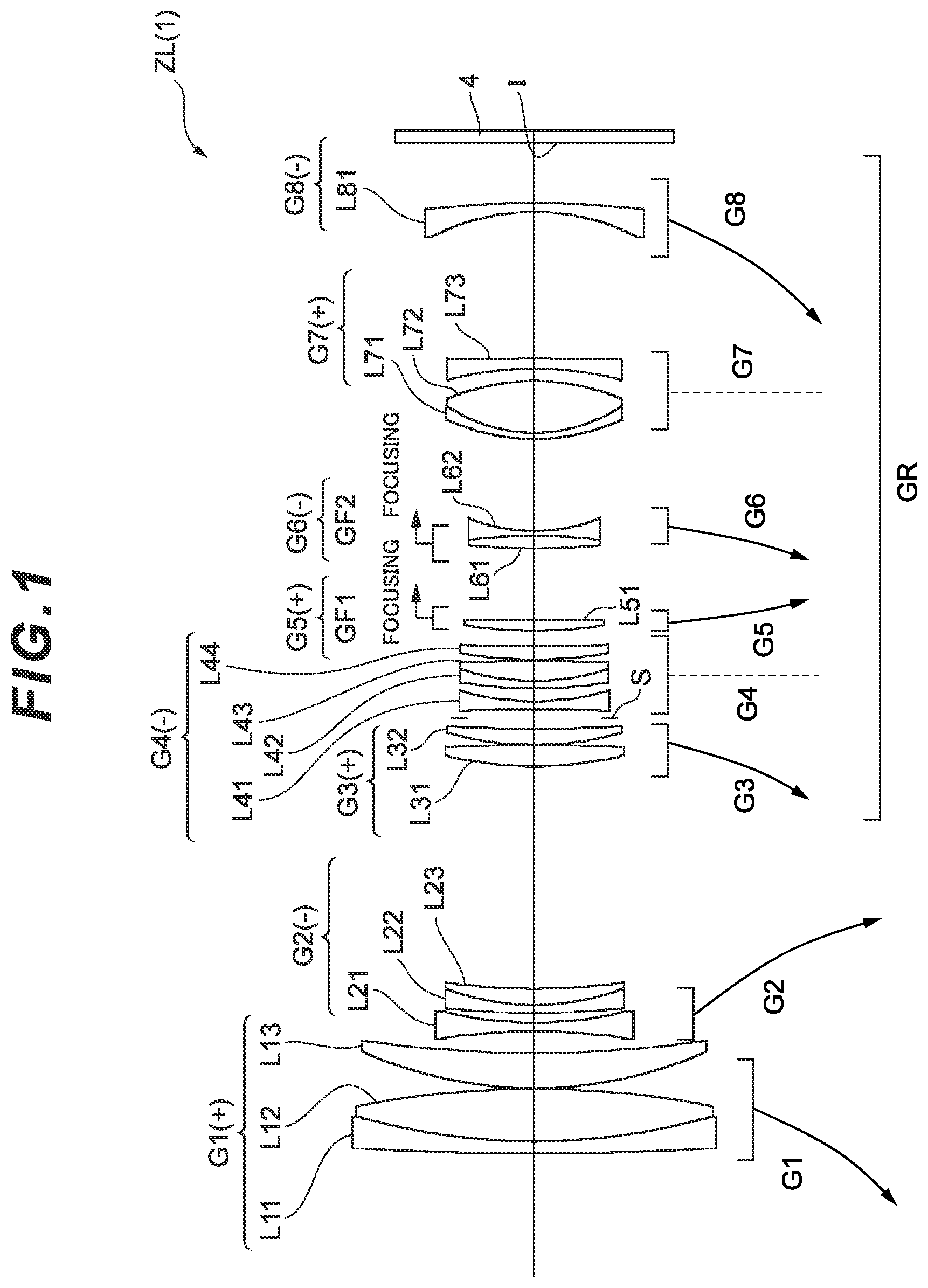
shows a lens configuration of a zoom optical system according to a first example;
A, 2 B and 2 C are graphs respectively showing various aberrations of the zoom optical system according to the first example upon focusing on infinity in a wide-angle end state, an intermediate focal length state, and a telephoto end state;
A, 3 B and 3 C are graphs respectively showing various aberrations of the zoom optical system according to the first example upon focusing on a short distance object in the wide-angle end state, the intermediate focal length state, and the telephoto end state;
shows a lens configuration of a zoom optical system according to a second example;
A, 5 B and 5 C are graphs respectively showing various aberrations of the zoom optical system according to the second example upon focusing on infinity in a wide-angle end state, an intermediate focal length state, and a telephoto end state;
A, 6 B and 6 C are graphs respectively showing various aberrations of the zoom optical system according to the second example upon focusing on a short distance object in the wide-angle end state, the intermediate focal length state, and the telephoto end state;
shows a lens configuration of a zoom optical system according to a third example;
A, 8 B and 8 C are graphs respectively showing various aberrations of the zoom optical system according to the third example upon focusing on infinity in a wide-angle end state, an intermediate focal length state, and a telephoto end state;
A, 9 B and 9 C are graphs respectively showing various aberrations of the zoom optical system according to the third example upon focusing on a short distance object in the wide-angle end state, the intermediate focal length state, and the telephoto end state;
shows a lens configuration of a zoom optical system according to a fourth example;
A, 11 B and 11 C are graphs respectively showing various aberrations of the zoom optical system according to the fourth example upon focusing on infinity in a wide-angle end state, an intermediate focal length state, and a telephoto end state;
A, 12 B and 12 C are graphs respectively showing various aberrations of the zoom optical system according to the fourth example upon focusing on a short distance object in the wide-angle end state, the intermediate focal length state, and the telephoto end state;
is a flowchart showing a method for manufacturing the zoom optical system according to this embodiment; and
shows a configuration of a camera that includes the zoom optical system according to this embodiment.
DESCRIPTION OF THE EMBODIMENTS
Hereinafter, preferable embodiments according to the present invention are described. First, a camera (optical apparatus) that includes a zoom optical system according to each embodiment is described with reference to . As shown in , this camera 1 includes a main body 2 , and a photographing lens 3 attached to the main body 2 . The main body 2 includes an imaging element 4 , a main body control part (not shown) that controls the operation of the digital camera, and a liquid crystal operation screen 5 . The photographing lens 3 includes an optical system ZL that includes a plurality of lens groups, and a lens position control mechanism (not shown) that controls the position of each lens group. The lens position control mechanism includes a sensor that detects the position of each lens group, a motor that moves each lens group forward and backward on the optical axis, and a control circuit that drives the motor.
Light from a photographic subject is condensed by the optical system ZL of the photographing lens 3 , and reaches an image surface I of the imaging element 4 . The light having reached the image surface I from the photographic subject is photoelectrically converted by the imaging element 4 , and is recorded as digital image data in a memory, not shown. The digital image data recorded in the memory is allowed to be displayed on the liquid crystal screen 5 according to an operation by a user. Note that this camera may be a mirrorless camera, or a single-lens reflex camera that includes a quick return mirror.
Next, the zoom optical system (photographing lens 3 ) according to this embodiment is described. As shown in , the zoom optical system ZL( 1 ) that is an example of the zoom optical system (zoom lens) ZL according to this embodiment consists of, in order from an object on an optical axis: a first lens group G 1 having a positive refractive power; a second lens group G 2 having a negative refractive power; and a rear group GR, wherein the rear group GR comprises a first focusing lens group GF 1 having a positive refractive power (including, for example, a fifth lens group G 5 ), and a second focusing lens group GF 2 having a negative refractive power (including, for example, a sixth lens group G 6 ). Upon zooming from a wide angle end to a telephoto end, distances between lens groups adjacent to each other among the first lens group G 1 , the second lens group G 2 , and the plurality of lens groups constituting the rear group GR, change. Furthermore, upon focusing from an infinity object to a short distance object, the first focusing lens group GF 1 and the second focusing lens group GF 2 move toward an image along movement trajectories different from each other.
Preferably, in this zoom optical system ZL, the following conditional expression (1) is satisfied, 1.10< f 2/ fF 2<2.00 (1)
•
• where f2: a focal length of the second lens group, and • fF2: a focal length of the second focusing lens group.
The conditional expression (1) defines the ratio between the focal lengths of the second lens group G 2 and the second focusing lens group GF 2 . By satisfying the conditional expression (1), the variation in various aberrations including the spherical aberration and the curvature of field upon focusing from the infinity object to the short distance object can be favorably suppressed. To further secure the advantageous effects of this embodiment, it is preferable to set the upper limit value of the conditional expression (1) to 1.85, 1.70, 1.60, 1.55, 1.50, 1.45, or 1.42, for example. It is preferable to set the lower limit value of the conditional expression (1) to 1.12, 1.14, 1.15, 1.16, 1.18, or 1.19, for example.
Preferably, in the zoom optical system described above, the following conditional expression (2) is satisfied, 0.30< f 1/ fF 1<2.50 (2)
•
• where f1: a focal length of the first lens group, and • fF1: a focal length of the first focusing lens group.
The conditional expression (2) defines the ratio between the focal lengths of the first lens group G 1 and the first focusing lens group GF 1 . By satisfying the conditional expression (2), the variation in various aberrations including the spherical aberration and the curvature of field upon focusing from the infinity object to the short distance object can be favorably suppressed. To further secure the advantageous effects of this embodiment, it is preferable to set the upper limit value of the conditional expression (2) to 2.45, 2.40, 2.35, 2.30, 2.25, 2.20, 2.15, 2.10, or 2.05, for example. It is preferable to set the lower limit value of the conditional expression (2) to 0.50, 0.75, 1.00, 1.15, 1.30, 1.40, 1.45, 1.50, or 1.55, for example.
Preferably, in the zoom optical system described above, the first focusing lens group GF 1 consists of one positive lens. Accordingly, the lens barrel can be reduced in size, and various aberrations including the spherical aberration upon focusing can be effectively suppressed.
Preferably, in the zoom optical system described above, the following conditional expression (3) is satisfied, 0.60< fr/fF 2<3.00 (3)
•
• where fr: a focal length of a lens group closest to the image.
The conditional expression (3) defines the ratio between the focal lengths of the lens group closest to the image and the second focusing lens group GF 2 . By satisfying the conditional expression (3), the variation in various aberrations including the spherical aberration upon focusing from the infinity object to the short distance object can be suppressed. To further secure the advantageous effects of this embodiment, it is preferable to set the upper limit value of the conditional expression (3) to 2.85, 2.70, 2.55, 2.40, 2.25, 2.10, 2.00, 1.95, or 1.92, for example. It is preferable to set the lower limit value of the conditional expression (3) to 0.75, 0.85, 0.93, 1.00, 1.05, 1.10, 1.15, or 1.20, for example.
Preferably, in the zoom optical system described above, the following conditional expression (4) is satisfied, 1.30< fF 1/(− fF 2)<10.00 (4)
The conditional expression (4) defines the ratio between the focal lengths of the first focusing lens group GF 1 and the second focusing lens group GF 2 . By satisfying the conditional expression (4), the variation in the various aberrations including the spherical aberration upon focusing from the infinity object to the short distance object can be favorably suppressed. To further secure the advantageous effects of this embodiment, it is preferable to set the upper limit value of the conditional expression (4) to 8.50, 7.00, 5.50, 4.50, 4.00, 3.50, 3.00, 2.50, or 2.30, for example. It is preferable to set the lower limit value of the conditional expression (4) to 1.35, 1.40, 1.45, 1.50, 1.55, 1.60, 1.63, or 1.65, for example.
Preferably, in the zoom optical system described above, the following conditional expression (5) is satisfied, 0.01< MWF 1/ MWF 2<1.00 (5)
•
• where MWF1: an amount of movement of the first focusing lens group upon focusing from the infinity object to the short distance object in a wide angle end state, and • MWF2: an amount of movement of the second focusing lens group upon focusing from the infinity object to the short distance object in the wide angle end state. • Note that movement toward an image surface is chosen to be positive.
The conditional expression (5) described above defines the ratio between the amount of movement of the first focusing lens group GF 1 upon focusing from the infinity object to the short distance object in the wide angle end state, and the amount of movement of the second focusing lens group GF 2 upon focusing from the infinity object to the short distance object in the wide angle end state. By satisfying the conditional expression (5), the variation in various aberrations including the spherical aberration upon focusing from the infinity object to the short distance object can be favorably suppressed. To further secure the advantageous effects of this embodiment, it is preferable to set the upper limit value of the conditional expression (5) to 0.95, 0.90, 0.88, 0.85, 0.83, 0.78, 0.75, 0.73, or 0.70, for example. It is preferable to set the lower limit value of the conditional expression (5) to 0.05, 0.10, 0.15, 0.20, 0.23, 0.25, 0.28, or 0.30, for example.
Preferably, in the zoom optical system described above, the second focusing lens group GF 2 consists of one positive lens and one negative lens. Accordingly, the variation in chromatic aberrations upon focusing from the infinity object to the short distance object can be effectively corrected.
In the zoom optical system described above, the first lens group G 1 comprises at least one positive lens, and the following conditional expression (6) is satisfied, 60.00< vp (6)
•
• where vp: an Abbe number of the positive lens included in the first lens group.
In the zoom optical system described above, the first lens group G 1 has a configuration of including at least one positive lens, and the positive lens satisfies the conditional expression (6), thereby allowing the longitudinal chromatic aberration to be effectively suppressed. To further secure the advantageous effects of this embodiment, it is preferable to set the lower limit value of the conditional expression (6) to 63.0, 68.0, 72.0, 75.0, 78.0, or 80.0, for example.
In the zoom optical system described above, it is preferable that at least part of the lens group adjacent to the first focusing lens group GF 1 on the object side be allowed to move in a direction perpendicular to the optical axis, and enable image blur correction to be achieved. Accordingly, image surface inclination and variation in decentering coma aberration upon camera shake correction can be effectively suppressed.
Preferably, in the zoom optical system described above, the following conditional expression (7) is satisfied, 0.10<β F 1 w< 0.80 (7)
•
• where βF1w: a lateral magnification of the first focusing lens group in a wide angle end state.
The conditional expression (7) defines the lateral magnification of the first focusing lens group GF 1 upon focusing on the infinity object in the wide angle end state. By satisfying the conditional expression (7), the variation in the various aberrations including the spherical aberration upon focusing from the infinity object to the short distance object in the wide angle end state can be favorably suppressed. To further secure the advantageous effects of this embodiment, it is preferable to set the upper limit value of the conditional expression (7) to 0.75, 0.70, 0.68, 0.65, 0.63, 0.60, 0.58, or 0.55, for example. It is preferable to set the lower limit value of the conditional expression (7) to 0.15, 0.20, 0.25, 0.30, 0.33, 0.35, or 0.38, for example.
Preferably, in the zoom optical system described above, the following conditional expression (8) is satisfied, 0.10<1/β F 2 w< 0.60 (8)
•
• where βF2w: a lateral magnification of the second focusing lens group in a wide angle end state.
The conditional expression (8) defines the lateral magnification of the second focusing lens group GF 2 upon focusing on the infinity object in the wide angle end state. By satisfying the conditional expression (8), the variation in the various aberrations including the spherical aberration upon focusing from the infinity object to the short distance object in the wide angle end state can be favorably suppressed. To further secure the advantageous effects of this embodiment, it is preferable to set the upper limit value of the conditional expression (8) to 0.55, 0.50, 0.48, 0.45, 0.43, 0.40, 0.38, or 0.35, for example. It is preferable to set the lower limit value of the conditional expression (8) to 0.13, 0.15, 0.18, 0.20, 0.23, or 0.25, for example.
Preferably, in the zoom optical system described above, the following conditional expression (9) is satisfied, (β F 1 w+ 1/β F 1 w ) −2 <0.25. (9)
The conditional expression (9) defines the relationship of the lateral magnification of the first focusing lens group GF 1 upon focusing on the infinity object in the wide angle end state. By satisfying the conditional expression (9), the various aberrations including the spherical aberration, the distortion and the coma aberration upon focusing from the infinity object to the short distance object in the wide angle end state can be suppressed while the amount of movement can be reduced. To further secure the advantageous effects of this embodiment, it is preferable to set the upper limit value of the conditional expression (9) to 0.24, 0.22, 0.21, 0.20, 0.19, or 0.18, for example.
Preferably, in the zoom optical system described above, the following conditional expression (10) is satisfied, (β F 2 w+ 1/(β F 2 w ) −2 <0.15. (10)
The conditional expression (10) defines the relationship of the lateral magnification of the second focusing lens group GF 2 upon focusing on the infinity object in the wide angle end state. By satisfying the conditional expression (10), the various aberrations including the spherical aberration, the distortion and the coma aberration upon focusing from the infinity object to the short distance object in the wide angle end state can be suppressed while the amount of movement can be reduced. To further secure the advantageous effects of this embodiment, it is preferable to set the upper limit value of the conditional expression (10) to 0.14, 0.13, 0.12, 0.11, or 0.10, for example.
Preferably, in the zoom optical system described above, the following conditional expression (11) is satisfied, 15.00°<2ω w< 45.00° (11)
•
• where 2ωw: a full angle of view [°] of the zoom optical system in a wide angle end state.
The conditional expression (11) defines the full angle of view of the zoom optical system in the wide angle end state. To further secure the advantageous effects of this embodiment, it is preferable to set the upper limit value of the conditional expression (11) to 044.00°, 42.00°, 40.00°, 38.00°, 36.00°, or 35.00°, for example. It is preferable to set the lower limit value of the conditional expression (11) to 18.00°, 20.00°, 23.00°, 25.00°, 28.00°, 30.00°, or 32.00°, for example.
Preferably, in the zoom optical system described above, the following conditional expression (12) is satisfied, 0.05< Bfw/fw< 0.35 (12)
•
• where Bfw: a back focus in a wide-angle end state, and • fw: a focal length of the zoom optical system in the wide angle end state.
The conditional expression (12) described above defines the ratio between the back focus of the zoom optical system in the wide angle end state, and the focal length of the zoom optical system in the wide angle end state. By satisfying the conditional expression (12), the various aberrations including the coma aberration in the wide angle end state can be effectively corrected. To further secure the advantageous effects of this embodiment, it is preferable to set the upper limit value of the conditional expression (12) to 0.34, 0.32, 0.30, 0.29, or 0.28, for example. It is preferable to set the lower limit value of the conditional expression (12) to 0.06, 0.08, 0.10, 0.12, or 0.14, for example.
Subsequently, referring to , a method for manufacturing the optical system is schematically described. According to the manufacturing method, first, a first lens group having a positive refractive power, a second lens group having a negative refractive power, and a rear group including a plurality of lens groups, which are in order from an object on the optical axis, are arranged (step ST1). Note that the rear group comprises a first focusing lens group having a positive refractive power, and a second focusing lens group having a negative refractive power. Next, configuration is made so that upon zooming from a wide angle end to a telephoto end, distances between lens groups adjacent to each other among the first lens group, the second lens group, and the plurality of lens groups, change (step ST2). Configuration is further made so that upon focusing from an infinity object to a short distance object, the first focusing lens group and the second focusing lens group move toward an image along movement trajectories different from each other (step ST3). The configuration is made so as to satisfy the following conditional expression (step ST4). 1.10< f 2/ fF 2<2.00
•
• where f2: a focal length of the second lens group, and • fF2: a focal length of the second focusing lens group.
The aforementioned zoom optical system according to this embodiment, and the camera (optical apparatus) including the zoom optical system, and the zoom optical system manufactured by the aforementioned manufacturing method can reduce the lens groups for focusing in size and weight, which can achieve high-speed AF and silence during AF without increasing the size of the lens barrel. Furthermore, the variation in aberrations upon zooming from the wide angle end state to the telephoto end state, and the variation in aberrations upon focusing from the infinity object to the short distance object, can be favorably suppressed.
EXAMPLES
Hereinafter, zoom optical systems ZL according to specific examples of the aforementioned embodiment are described with reference to the drawings. , 4 , 7 and 10 are sectional views showing the configurations and refractive power allocations of the zoom optical systems ZL {ZL( 1 ) to ZL( 4 )} according to the first to fourth examples. In each sectional view, the moving direction of each lens group on the optical axis upon zooming from the wide angle end state (W) to the telephoto end state (T) is indicated by an arrow. Furthermore, the moving direction of the focusing lens group upon focusing from infinity to a short distance object is indicated by an arrow accompanied by characters “FOCUSING”.
In these diagrams ( , 4 , 7 and 10 ), each lens group is represented by a combination of a symbol G and a numeral, and each lens is represented by a combination of a symbol L and a numeral. In this case, to prevent complication due to increase in the types and numbers of symbols and numerals, the lens groups and the like are represented using the combinations of symbols and numerals independently on an example-by-example basis. Accordingly, even when the same combination of a symbol and a numeral is used among the examples, such usage does not necessarily mean the same configuration.
A, 2 B and 2 C , A, 3 B and 3 C , A, 5 B and 5 C , A, 6 B and 6 C , A, 8 B and 8 C , A, 9 B and 9 C , A, 11 B and 11 C , and A, 12 B and 12 C show various aberrations of the zoom optical systems ZL( 1 ) to ZL( 4 ) according to the first to fourth examples. In these diagrams, FNO indicates the f-number, NA indicates the numerical aperture, and Y indicates the image height. The spherical aberration graph indicates the value of the f-number or the numerical aperture that corresponds to the maximum aperture. The astigmatism graph and the distortion graph each indicate the maximum value of the image height. The coma aberration graph indicates the value of the corresponding image height. The symbol d indicates d-line (λ=587.6 nm). The symbol g indicates g-line (λ=435.8 nm). In the astigmatism graph, a solid line indicates a sagittal image surface, and a broken line indicates a meridional image surface. The distortion graph shows the distortion with reference to d-line. The graph of chromatic aberration of magnification shows the chromatic aberration of magnification with reference to g-line.
Hereinafter, Tables 1 to 4 are shown. Among these tables, Table 1 is a table showing each data item in the first example, Table 2 is that in the second example, Table 3 is that in the third example, and Table 4 is that in the fourth example. In each example, for calculation of aberration characteristics, d-line (wavelength λ=587.6 nm), and g-line (wavelength λ=435.8 nm) are selected.
In the table of [General Data], F.NO indicates the f-number, and 2ω indicates the angle of view (the unit is ° (degrees), and co indicates the half angle of view). TL indicates, as the air equivalent length, a distance obtained by adding BF to the distance from the lens foremost surface to the lens last surface on the optical axis upon focusing on infinity. BF indicates the air equivalent distance (back focus) from the lens last surface to the image surface I on the optical axis upon focusing on infinity. Note that these values are indicated for corresponding zoom states at the wide-angle end (W), the intermediate focal length (M), and the telephoto end (T).
In the table of [Lens Data], Surface Number (the number of the field indicated by characters of Surface) indicates the order of the optical surface from the object side along the direction in which the ray travels, R indicates the radius of curvature (the surface whose center of curvature resides on the image side is regarded to have a positive value) of each optical surface, D indicates the distance on the optical axis from each optical surface to the next optical surface (or the image surface), nd is the refractive index of the material of the optical member for d-line, and vd indicates the Abbe number of the material of the optical member with reference to d-line. The radius of curvature “∞” indicates a plane or an opening. (Stop S) indicates an aperture stop. The description of the air refractive index nd=1.00000 is omitted. In a case where the lens surface is an aspherical surface, the surface number is assigned * symbol, and the field of the radius of curvature R indicates the paraxial radius of curvature.
In the table of [Aspherical Data], the shape of the aspherical surface indicated in [Lens Data] is indicated by the following expression (A). X(y) indicates the distance (sag amount) from the tangent plane at the vertex of the aspherical surface to the position on the aspherical surface at the height y in the optical axis direction. R indicates the radius of curvature (paraxial radius of curvature) of the reference spherical surface. κ indicates the conic constant. Ai indicates the i-th aspherical coefficient. “E-n” indicates “×10 −N ”. For example, 1.234 E−05=1.234×10 −5 . Note that the second-order aspherical coefficient A2 is zero, and the description thereof is omitted. X ( y )=( y 2 /R )/{1+(1−κ× y 2 /R 2 ) 1/2 }+A 4× y 4 +A 6× y 6 +A 8× y 8 +A 10 xy 10 +A 12× y 12 (A)
The table of [Lens Group Data] shows the first surface (the surface closest to the object) of each lens group, and the focal length of the corresponding lens group.
The table of [Variable Distance Data] shows the surface distance at each surface number where the surface distance is “Variable” in the table showing [Lens Data]. Here, for cases of focusing on infinity and a short distance, the surface distances in each of zooming states at the wide angle end (W), the intermediate focal length (M) and the telephoto end (T) are shown in a manner classified into a case of focusing at a normal distance and a case of focusing at a very short distance. Note that the first row indicates the entire focal length f (the case of focusing at the normal distance) or the lateral magnification β (the case of focusing at the very short distance) in each zooming state.
The table [Magnification] shows the lateral magnification βF1 of the first focusing lens group, and the lateral magnification βF2 of the second focusing lens group, in each of zooming states at the wide angle end (W), the intermediate focal length (M) and the telephoto end (T), in a manner classified into the case of focusing at the normal distance and the case of focusing at the very short distance.
The table [Other Data] shows the focal length fw of the zoom optical system ZL in the wide angle end state, the focal length ft of the zoom optical system ZL in the telephoto end state, the back focus Bfw in the wide angle end state, the focal length fF1 of the first focusing lens group GF 1 , the focal length fF2 of the second focusing lens group GF 2 , the focal length fr of the final lens group disposed closest to the image, and the amount of movement MWF1 of the first focusing lens group and the amount of movement MWF2 of the second focusing lens group upon zooming from the infinity object to the short distance object (shortest distance object) in the wide angle end state.
Tables of [Conditional Expression Corresponding Value] are provided at the end of the description of every example (first to fourth examples). This table collectively indicates values corresponding to the conditional expressions with respect to all the examples (first to fourth examples).
Hereinafter, at all the data values, the listed focal length f, radius of curvature R, surface distance D, other lengths and the like are generally represented in “mm” if not otherwise specified. However, even after subjected to proportional scaling in or out, the optical system can achieve equivalent optical performances. Accordingly, the representation is not limited thereto.
The descriptions of the tables so far are common to all the examples. Redundant descriptions are hereinafter omitted.
First Example
A first example is described with reference to to 3 A, 3 B and 3 C and Table 1. shows the lens configuration of a zoom optical system according to the first example. The zoom optical system ZL( 1 ) according to the first example consists of, in order from the object: a first lens group G 1 having a positive refractive power; a second lens group G 2 having a negative refractive power; a third lens group G 3 having a positive refractive power; an aperture stop S; a fourth lens group G 4 having a negative refractive power; a fifth lens group G 5 having a positive refractive power; a sixth lens group G 6 having a negative refractive power; a seventh lens group G 7 having a positive refractive power; and an eighth lens group G 8 having a negative refractive power. Note that an imaging element 4 that includes an image surface I is disposed on the image side of the eighth lens group G 8 .
Upon zooming from the wide-angle end state (W) to the telephoto end state (T), the first to third lens groups G 1 to G 3 , the fifth and sixth lens groups G 5 and G 6 , and the eighth lens group G 8 move in the axial direction as indicated by arrows in , and the distances between lens groups adjacent to each other change. Note that the fourth and seventh lens groups G 4 and G 7 are fixed and stationary upon zooming. Note that the lens group that consists of the third to eighth lens groups G 3 to G 8 corresponds to the rear group GR. A sign (+) or (−) assigned to each lens group symbol indicates the refractive power of the corresponding lens group. This indication similarly applies to all the following examples.
The first lens group G 1 consists of, in order from the object: a cemented lens including a negative meniscus lens L 11 having a convex surface facing the object, and a biconvex positive lens L 12 ; and a positive meniscus lens L 13 having a convex surface facing the object.
The second lens group G 2 consists of, in order from the object: a biconcave negative lens L 21 ; and a cemented lens including a negative meniscus lens L 22 having a convex surface facing the object, and a positive meniscus lens L 23 having a convex surface facing the object.
The third lens group G 3 consists of, in order from the object: a biconvex positive lens L 31 ; and a positive meniscus lens L 32 having a convex surface facing the object.
The fourth lens group G 4 consists of, in order from the object: an aperture stop S; a biconcave negative lens L 41 ; a cemented lens including a negative meniscus lens L 42 having a convex surface facing the object, and a biconvex positive lens L 43 ; and a positive meniscus lens L 44 having a convex surface facing the object. The aperture stop S is provided on the image side of the fourth lens group G 4 , and moves with the fourth lens group G 4 upon zooming. Preferably, configuration is made so as to move the cemented lens including the negative meniscus lens L 42 and the positive lens L 43 , and the positive meniscus lens L 44 perpendicularly to the optical axis, and thus constitute a vibration proof lens that achieves camera shake correction.
The fifth lens group G 5 consists of a positive meniscus lens L 51 having a convex surface facing the object. The fifth lens group G 5 constitutes a first focusing lens group GF 1 that is moved upon focusing.
The sixth lens group G 6 consists of a cemented lens including a biconvex positive lens L 61 and a biconcave negative lens L 62 . The sixth lens group G 6 constitutes a second focusing lens group GF 2 that is moved upon focusing.
The seventh lens group G 7 consists of, in order from the object: a cemented lens including a negative meniscus lens L 71 having a convex surface facing the object, and a biconvex positive lens L 72 ; and a negative meniscus lens L 73 having a concave surface facing the object.
The eighth lens group G 8 consists of a negative meniscus lens L 81 having a concave surface facing the object. A parallel plate PP is disposed before the image surface I.
In this example, as described above, the fifth lens group G 5 constitutes the first focusing lens group GF 1 , and the sixth lens group G 6 constitutes the second focusing lens group GF 2 . As the state of focusing on a long distance object (infinity object) is changed to the state of focusing on a short distance object, both the focusing lens groups GF 1 and GF 2 move toward the image as indicated by the arrows. Note that the movement trajectories are different from each other.
The following Table 1 lists values of data on the zoom optical system according to the first example.
TABLE 1
[General Data]
W M T
F.NO 4.0951 4.09535 4.09833
2ω 34.15798 19.5708 12.31288
Air equivalent TL 166.38 187.45 194.45
Air equivalent BF 11.1546 18.7416 26.5245
[Lens Data]
Surface R D nd νd
1 500.00 1.99 1.83400 37.18
2 105.771 8.57 1.49700 81.61
3 −149.176 0.10 1.00000
4 69.0714 5.76 1.49700 81.61
5 195.431 Variable 1.00000
6 −95.4875 1.39 1.77250 49.61
7 60.8786 1.60 1.00000
8 134.479 1.29 1.60300 65.4
9 40.9439 2.64 2.00069 25.46
10 100.515 Variable 1.00000
11 60.695 3.41 1.59319 67.87
12 −452.202 0.10 1.00000
13 51.5441 2.53 1.69680 55.48
14 171.456 Variable 1.00000
15 ∞ 1.40 1.00000 Aperture Stop
16 −348.825 1.29 1.72825 28.38
17 41.809 2.16 1.00000
18 74.9298 1.19 1.85000 27.03
19 38.2117 3.23 1.51680 63.8
20 −543.588 0.28 1.00000
21 71.1546 2.16 1.90265 35.72
22 311.075 Variable 1.00000
23 70.6244 1.79 1.75500 52.36
24 2710.11 Variable 1.00000
25 121.18 1.99 1.84666 23.8
26 −85.4601 0.79 1.77250 49.61
27 27.6526 Variable 1.00000
28 34.0186 0.99 1.90265 35.72
29 25.5061 8.47 1.51680 63.8
30 −36.1299 2.00 1.00000
31 −54.7648 1.70 1.72916 54.62
32 −1228.74 Variable 1.00000
33 −37.2066 1.49 1.80400 46.58
34 −150.0 Variable 1.00000
35 ∞ 2.00 1.51680 63.88
36 ∞ 0.10 1.00000
Image ∞
Surface
(I)
[Lens Group Data]
Group First surface Focal length
G1 1 151.18674
G2 6 −60.4899
G3 11 48.89599
G4 16 −193.87542
G5 23 96.01709
G6 25 −50.55695
G7 28 73.01107
G8 33 −61.90763
[Variable Distance Data]
W M T
Very Very Very
short short short
W M T distance distance distance
f 72.00 123.00 193.99 −0.08301 −0.138 −0.21187
d5 3.55932 39.103 61.1932 3.55932 39.103 61.1932
d10 36.3561 19.9769 1.08809 36.3561 19.9769 1.08809
d14 1.86104 3.7562 7.53637 1.86104 3.7562 7.53637
d22 2.50539 2.4 8.87949 4.68933 3.83126 12.50417
d24 11.711 9.41711 1.95377 13.89494 15.14216 14.64016
d21 15.058 17.468 18.4803 10.69012 10.31168 2.16923
d32 23.87795 16.29295 8.50055 23.87795 16.29295 8.50055
d34 9.73607 17.32302 25.1059 9.73607 17.32302 25.1059
[Magnification]
W M T
Very Very Very
short short short
W M T distance distance distance
βF1 0.47058 0.50753 0.6043 0.45172 0.45556 0.49556
βF2 3.46577 3.1914 2.86125 3.37937 3.04985 2.53862
[Other Data]
fw 72.003
ft 193.994
Bfw 11.155
fF1 96.017
fF2 −50.557
fr −61.91
MWF1 2.184
MWF2 4.368
A, 2 B and 2 C are graphs respectively showing various aberrations of the zoom optical system according to the first example upon focusing on infinity in a wide-angle end state, an intermediate focal length state, and a telephoto end state. A, 3 B and 3 C are graphs respectively showing various aberrations of the zoom optical system according to the first example upon focusing on a very short distance object in the wide-angle end state, the intermediate focal length state, and the telephoto end state.
In each of the graphs of A, 2 B and 2 C , FNO indicates the f-number, and Y indicates the image height. The spherical aberration graph indicates the value of the f-number corresponding to the maximum diameter. The astigmatism graph and the distortion graph each indicate the maximum value of the image height. The coma aberration graph indicates the value of the corresponding image height. In each of the graphs of A, 3 B and 3 C , NA indicates the numerical aperture, and Y indicates the image height. The spherical aberration graph indicates the value of the numerical aperture corresponding to the maximum diameter. The astigmatism graph and the distortion graph each indicate the maximum value of the image height. The coma aberration graph indicates the value of the corresponding image height. In each aberration graph, the symbol d indicates d-line (wavelength λ=587.6 nm). The symbol g indicates g-line (wavelength λ=435.8 nm). In the astigmatism graph, a solid line indicates a sagittal image surface, and a broken line indicates a meridional image surface. Note that also in the following aberration graphs in each example, symbols similar to those in this example are used, and redundant description is omitted.
The graphs showing various aberrations exhibit that the zoom optical system according to the first example favorably corrects various aberrations and has an excellent imaging performance from the wide angle end state to the telephoto end state, and further has an excellent imaging performance also upon focusing on the very short distance object.
Second Example
A second example is described with reference to to A, 6 B and 6 C and Table 2. shows the lens configuration of a zoom optical system according to the second example. The zoom optical system ZL( 2 ) according to the second example consists of, in order from the object: a first lens group G 1 having a positive refractive power; a second lens group G 2 having a negative refractive power; a third lens group G 3 having a positive refractive power; an aperture stop S; a fourth lens group G 4 having a negative refractive power; a fifth lens group G 5 having a positive refractive power; a sixth lens group G 6 having a negative refractive power; a seventh lens group G 7 having a positive refractive power; and an eighth lens group G 8 having a negative refractive power. Note that an imaging element 4 that includes an image surface I is disposed on the image side of the eighth lens group G 8 .
Upon zooming from the wide-angle end state (W) to the telephoto end state (T), the first to third lens groups G 1 to G 3 , the fifth and sixth lens groups G 5 and G 6 , and the eighth lens group G 8 move in the axial direction as indicated by arrows in , and the distances between lens groups adjacent to each other change. Note that the fourth and seventh lens groups G 4 and G 7 are fixed and stationary upon zooming. Note that the lens group that consists of the third to eighth lens groups G 3 to G 8 corresponds to the rear group GR.
The first lens group G 1 consists of, in order from the object: a cemented lens including a negative meniscus lens L 11 having a convex surface facing the object, and a biconvex positive lens L 12 ; and a positive meniscus lens L 13 having a convex surface facing the object.
The second lens group G 2 consists of, in order from the object: a biconcave negative lens L 21 ; and a cemented lens including a negative meniscus lens L 22 having a convex surface facing the object, and a positive meniscus lens L 23 having a convex surface facing the object.
The third lens group G 3 consists of, in order from the object: a biconvex positive lens L 31 ; and a cemented lens including a positive meniscus lens L 32 having a convex surface facing the object, and a positive meniscus lens L 33 having a convex surface facing the object.
The fourth lens group G 4 consists of, in order from the object: an aperture stop S; a biconcave negative lens L 41 ; a cemented lens including a negative meniscus lens L 42 having a convex surface facing the object, and a biconvex positive lens L 43 ; and a positive meniscus lens L 44 having a convex surface facing the object. The aperture stop S is provided on the image side of the fourth lens group G 4 , and moves with the fourth lens group G 4 upon zooming. Preferably, configuration is made so as to move the cemented lens including the negative meniscus lens L 42 and the positive lens L 43 , and the positive meniscus lens L 44 perpendicularly to the optical axis, and thus constitute a vibration proof lens that achieves camera shake correction.
The fifth lens group G 5 consists of a positive meniscus lens L 51 having a convex surface facing the object. The fifth lens group G 5 constitutes a first focusing lens group GF 1 that is moved upon focusing.
The sixth lens group G 6 consists of a cemented lens including a biconvex positive lens L 61 and a biconcave negative lens L 62 . The sixth lens group G 6 constitutes a second focusing lens group GF 2 that is moved upon focusing.
The seventh lens group G 7 consists of, in order from the object: a cemented lens including a negative meniscus lens L 71 having a convex surface facing the object, and a biconvex positive lens L 72 ; and a biconcave negative lens L 73 .
The eighth lens group G 8 consists of a negative meniscus lens L 81 having a concave surface facing the object. A parallel plate PP is disposed before the image surface I.
In this example, as described above, the fifth lens group G 5 constitutes the first focusing lens group GF 1 , and the sixth lens group G 6 constitutes the second focusing lens group GF 2 . As the state of focusing on a long distance object (infinity object) is changed to the state of focusing on a short distance object, both the focusing lens groups GF 1 and GF 2 move toward the image as indicated by the arrows. Note that the movement trajectories are different from each other.
The following Table 2 lists values of data on the zoom optical system according to the second example.
TABLE 2
[General Data]
W M T
F.NO 4.12046 4.11684 4.11125
2ω 34.23938 19.50486 12.29088
Air equivalent TL 169.454 187.456 197.586
Air equivalent BF 11.154 18.408 26.664
[Lens Data]
surface R D nd νd
1 731.131 1.99 1.83400 37.18
2 117.25 8.05 1.49700 81.61
3 −154.091 0.10 1.00000
4 77.0078 5.73 1.49700 81.61
5 281.511 Variable 1.00000
6 −94.2427 1.39 1.75500 52.36
7 72.1547 1.49 1.00000
8 169.537 1.29 1.61800 63.32
9 46.0722 2.56 2.00069 25.46
10 115.901 Variable 1.00000
11 59.2825 3.43 1.59319 67.87
12 −916.548 0.10 1.00000
13 55.8635 1.49 1.83481 42.75
14 61.9704 2.25 1.59319 67.87
15 174.424 Variable 1.00000
16 ∞ 1.33 1.00000 Aperture Stop
17 −585.399 1.29 1.72825 28.38
18 41.1729 1.98 1.00000
19 60.435 1.19 1.85000 27.03
20 34.9355 3.36 1.51680 63.88
21 −732.955 1.11 1.00000
22 76.1381 2.07 1.90265 35.72
23 267.9819 Variable 1.00000
24 52.4504 1.98 1.75500 52.36
25 449.41 Variable 1.00000
26 164.034 1.98 1.84666 23.8
27 −73.3989 0.79 1.71999 50.24
28 25.4685 Variable 1.00000
29 35.5194 0.99 1.90265 35.72
30 27.1214 8.22 1.51680 63.88
31 −34.5587 0.10 1.00000
32 −58.2316 1.70 1.75500 52.36
33 4997.29 Variable 1.00000
34 −36.5066 1.50 1.77250 49.61
35 −150.000 Variable 1.00000
36 ∞ 2.00 1.51680 63.88
37 ∞ 0.10 1.00000
Image ∞
Surface
(I)
[Lens Group Data]
Group First surface Focal length
f1 1 158.70211
f2 6 −65.8671
f3 11 54.45619
f4 17 −233.30838
f5 24 78.48149
f6 26 −47.29012
f7 29 76.27788
f8 34 −62.81955
[Variable Distance Data]
W M T
Very Very Very
short short short
W M T distance distance distance
Focal 72.00356 122.99682 193.99234 −0.08271 −0.13753 −0.20924
length
d5 3.37147 39.0174 63.0344 3.37147 39.0174 63.0344
d10 39.6223 19.3426 1.091 39.6223 19.3426 1.091
d15 1.85246 4.49489 8.84929 1.85246 4.49489 8.84929
d23 2.49998 3.09048 8.36222 6.21678 4.36326 10.59723
d25 9.83103 8.03148 1.95682 11.68943 13.1226 13.13184
d28 14.6269 15.8161 16.6366 9.0517 9.4522 3.22657
d33 27.02815 19.78715 11.52424 27.02815 19.78715 11.52424
d35 9.73551 16.98995 25.24534 9.73551 16.98995 25.24534
[Magnification]
W M T
Very Very Very
short short short
W M T distance distance distance
βF1 0.40348 0.44021 0.53916 0.38583 0.38343 0.41932
βF2 3.49235 3.23369 2.89849 3.37445 3.09912 2.61492
[Other Data]
fw 72.004
ft 193.992
Bfw 11.155
fF1 78.48149
fF2 −47.29012
fr −62.82
MWF1 3.717
MWF2 5.575
A, 5 B and 5 C are graphs respectively showing various aberrations of the zoom optical system according to the second example upon focusing on infinity in a wide-angle end state, an intermediate focal length state, and a telephoto end state. A, 6 B and 6 C are graphs respectively showing various aberrations of the zoom optical system according to the second example upon focusing on a very short distance object in the wide-angle end state, the intermediate focal length state, and the telephoto end state.
The graphs showing various aberrations exhibit that the zoom optical system according to the second example favorably corrects various aberrations and has an excellent imaging performance from the wide angle end state to the telephoto end state, and further has an excellent imaging performance also upon focusing on the very short distance object.
Third Example
A third example is described with reference to to 9 A, 9 B and 9 C and Table 3. shows the lens configuration of a zoom optical system according to the third example. The zoom optical system ZL( 3 ) according to the third example consists of, in order from the object: a first lens group G 1 having a positive refractive power; a second lens group G 2 having a negative refractive power; a third lens group G 3 having a positive refractive power; an aperture stop S; a fourth lens group G 4 having a positive refractive power; a fifth lens group G 5 having a negative refractive power; a sixth lens group G 6 having a positive refractive power; and a seventh lens group G 7 having a negative refractive power. Note that an imaging element 4 that includes an image surface I is disposed on the image side of the seventh lens group G 7 .
Upon zooming from the wide-angle end state (W) to the telephoto end state (T), the first to third lens groups G 1 to G 3 , the fifth lens group G 5 , and the seventh lens group G 7 move in the axial direction as indicated by arrows in , and the distances between lens groups adjacent to each other change. Note that the fourth and sixth lens groups G 4 and G 6 are fixed and stationary upon zooming. Note that the lens group that consists of the third to seventh lens groups G 3 to G 7 corresponds to the rear group GR.
The first lens group G 1 consists of, in order from the object: a cemented lens including a negative meniscus lens L 11 having a convex surface facing the object, and a biconvex positive lens L 12 ; and a positive meniscus lens L 13 having a convex surface facing the object.
The second lens group G 2 consists of, in order from the object: a biconcave negative lens L 21 ; and a cemented lens including a biconcave negative lens L 22 , and a positive meniscus lens L 23 having a convex surface facing the object.
The third lens group G 3 consists of, in order from the object: a biconvex positive lens L 31 ; and a cemented lens including a negative meniscus lens L 32 having a convex surface facing the object, and a positive meniscus lens L 33 having a convex surface facing the object.
The fourth lens group G 4 consists of, in order from the object: an aperture stop S; a negative meniscus lens L 41 having a convex surface facing the object; a cemented lens including a biconvex positive lens L 42 , and a negative meniscus lens L 43 having a concave surface facing the object; a positive meniscus lens L 44 having a convex surface facing the object; and a biconvex positive lens L 45 . The aperture stop S is provided on the image side of the fourth lens group G 4 , and moves with the fourth lens group G 4 upon zooming. The positive lens L 45 closest to the image constitutes a first focusing lens group GF 1 that is moved upon focusing. Note that the table of [Lens Data] described later indicates that the surface distance of the surface number 23 is variable, but the distance does not change upon zooming, and when the second focusing lens group GF 2 is moved for focusing, the distance changes. Preferably, configuration is made so as to move the cemented lens including the positive lens L 42 and the negative meniscus lens L 43 , and the positive meniscus lens L 44 perpendicularly to the optical axis, and thus constitute a vibration proof lens that achieves camera shake correction.
The fifth lens group G 5 consists of a cemented lens including a biconvex positive lens L 51 and a biconcave negative lens L 52 . The fifth lens group G 5 constitutes a second focusing lens group GF 2 that is moved upon focusing.
The sixth lens group G 6 consists of a cemented lens that includes a biconvex positive lens L 61 , and a negative meniscus lens L 62 having a concave surface facing the object.
The seventh lens group G 7 consists of a negative meniscus lens L 71 having a concave surface facing the object. A parallel plate PP is disposed before the image surface I.
In this example, as described above, the positive lens L 45 that is in the fourth lens group G 4 and is closest to the image constitutes the first focusing lens group GF 1 , and the fifth lens group G 5 constitutes the second focusing lens group GF 2 . As the state of focusing on a long distance object (infinity object) is changed to the state of focusing on a short distance object, both the focusing lens groups GF 1 and GF 2 move toward the image as indicated by the arrows. Note that the movement trajectories are different from each other.
The following Table 3 lists values of data on the zoom optical system according to the third example.
TABLE 3
[General Data]
W M T
F.NO 4.13522 4.13658 4.15089
2ω 34.0079 19.00672 12.21052
Air equivalent TL 167.955 187.453 194.407
Air equivalent BF 18.532 27.144 34.218
[Lens Data]
surface R D nd νd
1 234.377 2.00 1.83400 37.18
2 97.0845 7.50 1.49700 81.61
3 −226.442 0.10 1.00000
4 81.4145 5.10 1.49700 81.61
5 262.943 Variable 1.00000
6 −226.35 1.40 1.80400 46.58
7 52.3491 5.40 1.00000
8 −91.8819 1.30 1.48749 70.45
9 72.8406 2.40 2.00069 25.46
10 4047.79 Variable 1.00000
11 34.7784 4.60 1.59319 67.87
12 −340.051 0.34 1.00000
13 28.694 1.50 1.95000 29.37
14 20.7204 3.63 1.60300 65.4
15 50.6694 Variable 1.00000
16 ∞ 1.18 1.00000 Aperture Stop
17* 570.28 1.30 1.67798 54.85
18 24.2385 2.47 1.00000
19 43.9463 4.01 1.49700 81.61
20 −31.9719 1.20 1.80610 40.98
21 −74.7571 1.10 1.00000
22 27.7311 1.75 1.76684 46.76
23 29.9997 Variable 1.0000
24 60.5913 2.28 1.59319 67.87
25 −735.683 Variable 1.00000
26 148.715 2.20 1.84666 23.8
27 −65.4915 0.80 1.76802 49.23
28* 25.2641 Variable 1.00000
29* 160.588 7.41 1.69680 55.52
30 −19.8672 1.00 1.80610 40.98
31 −43.9193 Variable 1.00000
32 −45.2889 1.50 1.80400 46.58
33 −150.000 Variable 1.00000
34 ∞ 2.00 1.51680 63.88
35 ∞ 0.10 1.00000
Image ∞
Surface
(I)
[Aspherical Surface Data]
Surface κ A4 A6 A8 A10
17 1.000 −1.76E−06 2.13E−10 −8.42E−13 0.00E+00
28 1.000 1.38E−06 −2.40E−08 2.04E−10 −9.35E−13
29 1.000 3.99E−06 6.78E−09 −2.24E−11 5.80E−14
[Lens Group Data]
Group First surface Focal length
f1 1 153.035
f2 6 −58.27
f3 11 40.05
f4 17 602.05
f5 26 −43.08
f6 29 58.97
f7 32 −81.21
[Variable Distance Data]
W M T
Very Very Very
short short short
W M T distance distance distance
Focal 69.48393 122.99632 193.89295 −0.08017 0.13595 −0.20886
length
d5 2.43672 40.9882 66.3218 2.43672 40.9882 66.3218
d10 40.4348 20.6034 1.10004 40.4348 20.6034 1.10004
d123 2.16266 2.94747 4.07623 2.16266 2.94747 4.07623
d25 2.50063 2.50063 2.50063 3.50608 3.94625 3.57887
d28 9.19788 8.52466 3.17703 11.20878 14.30715 16.11589
d31 9.03572 9.71207 15.0604 6.01937 2.48396 1.0433
d33 20.19181 11.56998 4.48998 20.19181 11.56998 4.48998
d35 17.11364 25.72577 32.79941 17.11364 25.72577 32.79941
[Magnification]
W M T
Very Very Very
short short short
W M T distance distance distance
βF1 0.53854 0.56554 0.635 0.51982 0.51285 0.51888
βF2 3.56137 3.0828 2.8363 3.49135 2.91501 2.51092
[Other Data]
fw 69.484
ft 193.893
Bfw 18.532
fF1 94.473
fF2 −43.079
fr −81.21
MWF1 1.005
MWF2 3.016
A, 8 B and 8 C are graphs respectively showing various aberrations of the zoom optical system according to the third example upon focusing on infinity in a wide-angle end state, an intermediate focal length state, and a telephoto end state. A, 9 B and 9 C are graphs respectively showing various aberrations of the zoom optical system according to the third example upon focusing on a very short distance object in the wide-angle end state, the intermediate focal length state, and the telephoto end state.
The graphs showing various aberrations exhibit that the zoom optical system according to the third example favorably corrects various aberrations and has an excellent imaging performance from the wide angle end state to the telephoto end state, and further has an excellent imaging performance also upon focusing on the very short distance object.
Fourth Example
A fourth example is described with reference to to 12 A, 12 B and 12 C and Table 4. shows the lens configuration of a zoom optical system according to the fourth example. The zoom optical system ZL( 4 ) according to the fourth example consists of, in order from the object: a first lens group G 1 having a positive refractive power; a second lens group G 2 having a negative refractive power; a third lens group G 3 having a positive refractive power; an aperture stop S; a fourth lens group G 4 having a negative refractive power; a fifth lens group G 5 having a positive refractive power; a sixth lens group G 6 having a negative refractive power; and a seventh lens group G 7 having a negative refractive power. Note that an imaging element 4 that includes an image surface I is disposed on the image side of the seventh lens group G 7 .
Upon zooming from the wide-angle end state (W) to the telephoto end state (T), the first to third lens groups G 1 to G 3 , the fifth lens group G 5 , and the seventh lens group G 7 move in the axial direction as indicated by arrows in , and the distances between lens groups adjacent to each other change. Note that the fourth and sixth lens groups G 4 and G 6 are fixed and stationary upon zooming. Note that the lens group that consists of the third to seventh lens groups G 3 to G 7 corresponds to the rear group GR.
The first lens group G 1 consists of, in order from the object: a cemented lens including a negative meniscus lens L 11 having a convex surface facing the object, and a biconvex positive lens L 12 ; and a positive meniscus lens L 13 having a convex surface facing the object.
The second lens group G 2 consists of, in order from the object: a biconcave negative lens L 21 ; and a cemented lens including a negative meniscus lens L 22 having a convex surface facing the object, and a positive meniscus lens L 23 having a convex surface facing the object.
The third lens group G 3 consists of, in order from the object: a positive meniscus lens L 31 having a convex surface facing the object; and a cemented lens including a negative meniscus lens L 32 having a convex surface facing the object, and a positive meniscus lens L 33 having a convex surface facing the object.
The fourth lens group G 4 consists of, in order from the object: an aperture stop S; a negative meniscus lens L 41 having a convex surface facing the object; a cemented lens including a negative meniscus lens L 42 having a convex surface facing the object, and a biconvex positive lens L 43 ; and a positive meniscus lens L 44 having a convex surface facing the object. The aperture stop S is provided on the image side of the fourth lens group G 4 , and moves with the fourth lens group G 4 upon zooming. Preferably, configuration is made so as to move the cemented lens including the negative meniscus lens L 42 and the positive lens L 43 , and the positive meniscus lens L 44 perpendicularly to the optical axis, and thus constitute a vibration proof lens that achieves camera shake correction.
The fifth lens group G 5 consists of a positive meniscus lens L 51 having a convex surface facing the object. The fifth lens group G 5 constitutes a first focusing lens group GF 1 that is moved upon focusing.
The sixth lens group G 6 consists of, in order from the object: a cemented lens including a biconvex positive lens L 61 , and a biconcave negative lens L 62 ; a negative meniscus lens L 63 having a convex surface facing the object; a biconvex positive lens L 64 ; and a biconcave negative lens L 65 . The cemented lens including the biconvex positive lens L 61 and the biconcave negative lens L 62 constitutes the second focusing lens group GF 2 that is moved upon focusing. Note that the table of [Lens Data] described later indicates that the surface distance of the surface number 28 is variable, but the distance does not change upon zooming, and when the second focusing lens group GF 2 is moved for focusing, the distance changes.
The seventh lens group G 7 consists of a negative meniscus lens L 71 having a concave surface facing the object. A parallel plate PP is disposed before the image surface I.
In this example, as described above, the fifth lens group G 5 constitutes the first focusing lens group GF 1 , and the cemented lens that includes the biconvex positive lens L 61 and biconcave negative lens L 62 and is disposed on the object side of the sixth lens group G 6 constitutes the second focusing lens group GF 2 . As the state of focusing on a long distance object (infinity object) is changed to the state of focusing on a short distance object, both the focusing lens groups GF 1 and GF 2 move toward the image as indicated by the arrows. Note that the movement trajectories are different from each other.
The following Table 4 lists values of data on the zoom optical system according to the fourth example.
TABLE 4
[General Data]
W M T
F.NO 4.1497 4.12738 4.10277
2ω 34.12502 19.2871 12.14344
Air equivalent TL 169.45464 187.46147 197.45586
Air equivalent BF 11.15474 16.97645 24.33136
[Lens Data]
surface R D nd νd
1 554.111 1.99 1.83400 37.18
2 121.117 7.95 1.49700 81.61
3 −154.679 0.10 1.00000
4 82.3981 5.45 1.49700 81.61
5 300.000 Variable 1.00000
6 −89.8369 1.39 1.75500 52.36
7 72.7319 1.48 1.00000
8 169.21 1.29 1.61800 63.32
9 43.4531 2.58 2.00069 25.46
10 105.254 Variable 1.00000
11 72.6136 2.81 1.59319 67.87
12 630.043 0.10 1.00000
13 39.6925 1.49 1.83481 42.75
14 29.7546 3.87 1.59319 67.87
15 153.618 Variable 1.00000
16 ∞ 1.01 1.00000 Aperture Stop
17 255.742 1.29 1.72825 28.38
18 38.3739 2.14 1.00000
19 62.1964 1.19 1.85000 27.03
20 36.9077 3.39 1.51680 63.88
21 −312.986 0.78 1.00000
22 75.7193 2.01 1.90265 35.72
23 209.183 Variable 1.00000
24 45.8893 1.90 1.75500 52.36
25 154.217 Variable 1.00000
26 117.662 2.00 1.84666 23.8
27 −84.4172 0.79 1.71999 50.24
28 24.8653 Variable 1.00000
29 38.098 1.00 1.90265 35.72
30 29.1903 0.21 1.00000
31 29.368 7.78 1.51680 63.88
32 −34.236 0.16 1.00000
33 −58.6977 1.70 1.75500 52.36
34 1488.85 Variable 1.00000
35 −36.7886 1.50 1.77250 49.61
36 −150.000 Variable 1.00000
37 ∞ 2.00 1.51680 63.88
38 ∞ 0.10 1.00000
Image ∞
Surface
(I)
[Lens Group Data]
Group First surface Focal length
f1 1 156.21
f2 6 −62.97
f3 11 60.19
f4 17 −694.45
f5 24 85.88
f6 26 −253.27
f7 35 −63.46
[Variable Distance Data]
W M T
Very Very Very
short short short
W M T distance distance distance
Focal 72.007 122.99682 193.99136 −0.08258 −0.13692 −0.2071
length
d5 3.3891 39.252 62.9142 3.3891 39.252 62.9142
d10 39.6077 19.165 1.08983 39.6077 19.165 1.08983
d15 1.90568 4.49493 8.90891 1.90568 4.49493 8.90891
d23 2.50001 4.30027 10.75681 6.3024 5.41764 11.81545
d25 10.2319 8.42371 1.95605 12.13309 14.01054 14.65975
d28 15.6253 15.6253 15.6253 9.92172 8.9211 1.86296
d34 25.71179 19.89539 12.53498 25.71179 19.89539 12.53498
d36 9.73618 15.55788 22.91866 9.73618 15.55788 22.91866
[Magnification]
W M T
Very Very Very
short short short
W M T distance distance distance
βF1 0.44457 0.47652 0.56971 0.4298 0.42123 0.44706
βF2 3.05967 2.89463 2.65901 2.946 2.76102 2.38474
[Other Data]
fw 72.007
ft 193.991
Bfw 11.155
fF1 85.880052
fF2 −50.17732
fr −63.46
MWF1 3.802
MWF2 5.704
A, 11 B and 11 C are graphs respectively showing various aberrations of the zoom optical system according to the fourth example upon focusing on infinity in a wide-angle end state, an intermediate focal length state, and a telephoto end state. A, 12 B and 12 C are graphs respectively showing various aberrations of the zoom optical system according to the fourth example upon focusing on a very short distance object in the wide-angle end state, the intermediate focal length state, and the telephoto end state.
The graphs showing various aberrations exhibit that the zoom optical system according to the fourth example favorably corrects various aberrations and has an excellent imaging performance from the wide angle end state to the telephoto end state, and further has an excellent imaging performance also upon focusing on the very short distance object.
Lastly, the table of [Conditional Expression Corresponding Value] is shown below. This table collectively indicates values corresponding to the conditional expressions (1) to (11) with respect to all the examples (first to fifth examples). 1.10< f 2/ fF 2<2.00 Conditional expression (1) 0.30< f 1/ fF 1<2.50 Conditional expression (2) 0.60< fr/fF 2<3.00 Conditional expression (3) 1.30< fF 1/(− fF 2)<10.00 Conditional expression (4) 0.01< MWF 1/ MWF 2<1.00 Conditional expression (5) 60.00< vp Conditional expression (6) 0.10<β F 1 w< 0.80 Conditional expression (7) 0.10<1/ PF 2 w< 0.60 Conditional expression (8) (β F 1 w+ 1/β F 1 w ) −2 <0.25 Conditional expression (9) (β F 2 w+ 1/β F 2 w ) −2 <0.15 Conditional expression (10) 15.00°<2ω w< 45.00° Conditional expression (11) 0.05< Bfw/fw< 0.35 Conditional expression (12) [Conditional Expression Corresponding Value]
Conditional 1st 2nd 3rd 4th
Expression Example Example Example Example
(1) 1.196 1.393 1.353 1.255
(2) 1.575 2.022 1.620 1.819
(3) 1.225 1.328 1.885 1.265
(4) 1.899 1.660 2.193 1.712
(5) 0.500 0.667 0.333 0.667
(6) 81.61 81.61 81.61 81.61
(7) 0.471 0.403 0.539 0.445
(8) 0.289 0.286 0.281 0.327
(9) 0.148 0.120 0.174 0.138
(10) 0.071 0.070 0.068 0.087
(11) 34.158 34.239 34.008 34.125
(12) 0.155 0.155 0.267 0.155
The first to fourth examples described above show specific examples of this embodiment. This embodiment is not limited to these examples.
Note that the following content can be adopted in a range without impairing the optical performance of the zoom optical system according to this embodiment.
As numerical examples of the zoom optical systems, those having the seven- and eight-group structures are described. However, the present application is not limited thereto. A zoom optical system having another group configuration (e.g., a nine-group structure etc.) may be made. Specifically, a configuration may be adopted where a lens or a lens group is added to a place closest to the object or a place closest to the image surface in the zoom optical system. Note that the lens group indicates a portion that includes at least one lens separated by air distances that change during zooming.
The lens surface may be made of a spherical surface or a planar surface, or an aspherical surface. A case where the lens surface is a spherical surface or a planar surface is preferable, because lens processing, and assembling and adjustment are facilitated, and the optical performance degradation due to errors caused by processing and assembling and adjustment can be prevented. It is also preferable because the degradation in representation performance even with the image surface being misaligned is small.
In the cases where the lens surface is an aspherical surface, the aspherical surface may be any of an aspherical surface made by a grinding process, a glass mold aspherical surface made by forming glass into an aspherical shape with a mold, and a composite type aspherical surface made by forming a resin on a surface of glass into an aspherical shape. The lens surface may be a diffractive surface. The lens may be a gradient-index lens (GRIN lens), or a plastic lens.
As to the aperture stop, a member as the aperture stop is not necessarily provided, and a lens frame may replace the member to function instead.
An antireflection film having a high transmissivity in a wide wavelength region may be applied onto each lens surface in order to reduce flares and ghosts and achieve optical performances having a high contrast. This can reduce flares and ghosts, and achieve optical performances having a high contrast.
Explanation of Numerals and Characters
G1 First lens group G2 Second lens group
G3 Third lens group G4 Fourth lens group
G5 Fifth lens group G6 Sixth lens group
G7 Seventh lens group G8 Eighth lens group
GR Rear group S Aperture stop
GF1 First focusing lens group GF2 Second focusing lens group
I Image surface 4 Imaging element
Figures (20)
Citations
This patent cites (6)
- US5241421
- US2014/0139722
- US2019/0369371
- US2020/0233191
- USH03-225308
- US2014-102462