Abstract
A shape measuring device includes: a first light radiating unit to radiate first line light and second line light; a first image capturing unit to capture an object; and a measuring unit to measure a shape of the object on a basis of a first image and second images.
Claims (13)
1 . A shape measuring device comprising: a first light radiating unit including at least one light source to radiate first line light and second line light, the first line light being linear light, the second line light being linear light; a first image capturing unit including a camera having a first field of view, to capture an object passing through a first measurement region, and to capture the object passing through a second measurement region different from the first measurement region, the first measurement region being a region where a first plane through which the first line light passes and the first field of view intersect with each other, the second measurement region being a region where a second plane through which the second line light passes and the first field of view intersect with each other, the second measurement region being located on the first light radiating unit side from the first measurement region; and a measuring unit including processing circuitry configured to measure a shape of the object on a basis of a first image that is an image of a part of the object passing through the first measurement region and second images that are images of parts of the object passing through the second measurement region, the part of the object passing through the first measurement region being irradiated with the first line light, the parts of the object passing through the second measurement region being irradiated with the second line light, wherein the processing circuitry is further configured to measure the shape of the object including a height of the object based on a determination of whether an image of a line light projected on the object is an image of the first line light or an image of the second line light.
13 . A shape measuring device comprising: a first light radiating unit including at least one light source to radiate first line light and second line light, the first line light being linear light, the second line light being linear light; a first image capturing unit including a camera having a first field of view, to capture an object passing through a first measurement region, and to capture the object passing through a second measurement region different from the first measurement region, the first measurement region being a region where a first plane through which the first line light passes and the first field of view intersect with each other, the second measurement region being a region where a second plane through which the second line light passes and the first field of view intersect with each other, the second measurement region being located on the first light radiating unit side from the first measurement region; a measuring unit including processing circuitry configured to measure a shape of the object on a basis of a first image that is an image of a part of the object passing through the first measurement region and second images that are images of parts of the object passing through the second measurement region, the part of the object passing through the first measurement region being irradiated with the first line light, the parts of the object passing through the second measurement region being irradiated with the second line light; a second light radiating unit to radiate third line light and fourth line light, the third line light being linear light, the fourth line light being linear light; and a second image capturing unit having a second field of view different from the first field of view, to capture the object passing through a third measurement region, and to capture the object passing through a fourth measurement region different from the third measurement region, the third measurement region being a region where a third plane through which the third line light passes and the second field of view intersect with each other, the fourth measurement region being a region where a fourth plane through which the fourth line light passes and the second field of view intersect with each other, the fourth measurement region being located on the second light radiating unit side from the third measurement region, wherein the measuring unit measures the shape of the object on a basis of the first image, the second images, a third image, and a fourth image, the third image being an image a part, which being irradiated with the third line light, of the object passing through the third measurement region, the fourth image being an image a part, which being irradiated with the fourth line light, of the object passing through the fourth measurement region.
Show 11 dependent claims
2 . The shape measuring device according to claim 1 , wherein a second angle of incidence is equal to or larger than a first angle of incidence, the second angle of incidence being an angle of incidence made by the second line light incident on the object, the first angle of incidence being an angle of incidence made by the first line light incident on the object.
3 . The shape measuring device according to claim 2 , wherein the second angle of incidence is larger than the first angle of incidence.
4 . The shape measuring device according to claim 2 , wherein in a direction along a height of the object from a datum plane on which the object is placed, either a length of the first measurement region or a length of the second measurement region is equal to or shorter than the other.
5 . The shape measuring device according to claim 4 , wherein the length of the first measurement region is shorter than the length of the second measurement region.
6 . The shape measuring device according to claim 1 , wherein a focal point of the first line light is included in the first measurement region.
7 . The shape measuring device according to claim 1 , wherein a focal point of the second line light is included in the second measurement region.
8 . The shape measuring device according to claim 1 , further comprising: a second light radiating unit to radiate third line light and fourth line light, the third line light being linear light, the fourth line light being linear light; and a second image capturing unit having a second field of view different from the first field of view, to capture the object passing through a third measurement region, and to capture the object passing through a fourth measurement region different from the third measurement region, the third measurement region being a region where a third plane through which the third line light passes and the second field of view intersect with each other, the fourth measurement region being a region where a fourth plane through which the fourth line light passes and the second field of view intersect with each other, the fourth measurement region being located on the second light radiating unit side from the third measurement region, wherein the measuring unit measures the shape of the object on a basis of the first image, the second images, a third image, and a fourth image, the third image being an image a part, which being irradiated with the third line light, of the object passing through the third measurement region, the fourth image being an image a part, which being irradiated with the fourth line light, of the object passing through the fourth measurement region.
9 . The shape measuring device according to claim 8 , wherein a radiation direction of the third line light and a radiation direction of the fourth line light are different from a radiation direction of the first line light and a radiation direction of the second line light.
10 . The shape measuring device according to claim 1 , wherein an intensity of the first line light is different than an intensity of the second line light.
11 . The shape measuring device according to claim 1 , wherein a wavelength of the first line light is different than a wavelength of the second line light.
12 . The shape measuring device according to claim 1 , wherein: the first light radiating unit includes a first spot light source, a second spot light source, a collimating lens that collimates light emitted from the first and second spot light sources, and a cylindrical lens that converts a pattern of light collimated by the collimating lens to the first line light and the second line light.
Full Description
Show full text →
CROSS-REFERENCE TO RELATED APPLICATION
This application is based on PCT filing PCT/JP2021/019128, filed May 20, 2021, the entire contents of which are incorporated herein by reference.
TECHNICAL FIELD
The present disclosure relates to a shape measuring device.
BACKGROUND ART
Contact and non-contact measurement methods are known as methods for measuring a three-dimensional shape of an object. As a non-contact measurement method, the optical cutting method is widely used. In the light cutting method, for example, line light is radiated from a light radiating unit toward the object, and the image of the line light projected on the object is captured by the image capturing unit. In this case, a direction of a field of view of the image capturing unit is different from a radiation direction of the line light. In a shape measuring device employing the light cutting method, a position of the object is moved relative to an optical system including the light radiating unit and the image capturing unit, and thus the three-dimensional shape of the object is measured on the basis of the images that are sequentially obtained.
The resolving power of the shape measuring device is the value obtained by dividing the field of view of the image capturing unit by the number of pixels. For that reason, when a range of measurement in a direction along the height of the object is extended, the resolving power decreases. In order to prevent the resolving power from decreasing, a shape measuring device including two image capturing units is known. See, for example, Patent Reference 1.
PRIOR ART REFERENCE
Patent Reference
•
• Patent Reference 1: Japanese Patent Application Publication No. 2015-114235
SUMMARY OF THE INVENTION
Problem to be Solved by the Invention
However, the configuration in Patent Reference 1 has a problem of high cost because the configuration includes two image capturing units. Also, in the configuration in Patent Reference 1, the amount of image data required for measurement processing increases, and thus there is also a problem in that a load on calculations increases. In addition, the configuration in Patent Reference 1 requires synchronous control to synchronize the images captured by the two image capturing units, and thus there is also a problem in that a device is complicated.
It is an object of the present disclosure to provide a shape measuring device that is simplified and can reduce a load on calculations at low cost.
Means of Solving the Problem
A shape measuring device according to an aspect of the present disclosure includes: a first light radiating unit to radiate first line light and second line light, the first line light being linear light, the second line light being linear light; a first image capturing unit having a first field of view, to capture an object passing through a first measurement region, and to capture the object passing through a second measurement region different from the first measurement region, the first measurement region being a region where a first plane through which the first line light passes and the first field of view intersect with each other, the second measurement region being a region where a second plane through which the second line light passes and the first field of view intersect with each other, the second measurement region being located on the first light radiating unit side from the first measurement region; and a measuring unit to measure a shape of the object on a basis of a first image that is an image of a part of the object passing through the first measurement region and second images that are images of parts of the object passing through the second measurement region, the part of the object passing through the first measurement region being irradiated with the first line light, the parts of the object passing through the second measurement region being irradiated with the second line light.
Effects of the Invention
According to the present disclosure, it is possible to provide the shape measuring device that is simplified and can reduce a load on calculations at low cost.
BRIEF DESCRIPTION OF THE DRAWINGS
is a perspective view showing a schematic structure of a shape measuring device according to a first embodiment and a first object.
is a diagram of the shape measuring device and the first object shown in as seen in an X-axis direction.
is a diagram of the shape measuring device according to the first embodiment and the first object at a point in time of a start of measurement as seen in the X-axis direction.
A and 4 B are diagrams showing an example of a transition of an image captured by an image capturing unit shown in to 3 when the first object passes through a first measurement region.
A is a diagram of the shape measuring device according to the first embodiment and a second object at a point in time of a start of measurement as seen in the X-axis direction. B is a diagram of the shape measuring device according to the first embodiment and the second object passing through a second measurement region after the start of the measurement as seen in the X-axis direction.
A to 6 D are diagrams showing an example of a transition of an image captured by the image capturing unit shown in A and 5 B when the second object passes through the second measurement region.
is a diagram of a shape measuring device according to a second embodiment and an object as seen in the X-axis direction.
is a diagram of a shape measuring device according to a third embodiment and an object as seen in the X-axis direction.
is a diagram of a shape measuring device according to a fourth embodiment and an object as seen in the X-axis direction.
MODE FOR CARRYING OUT THE INVENTION
Shape measuring devices according to embodiments of the present disclosure will now be described below with reference to the attached drawings. The following embodiments are merely examples, and the embodiments may be combined as appropriate and each embodiment may be modified as appropriate.
The shape measuring devices according to the embodiments measure a three-dimensional shape of a measurement object (hereafter, also referred to as an “object”) with the optical cutting method. In order to facilitate understanding of the description, the drawings show the coordinate axes of an XYZ orthogonal coordinate system. The X axis and the Y axis are coordinate axes parallel to a datum plane S on which the object is placed. The Y axis is a coordinate axis parallel to a scanning direction of the shape measuring device. The Z axis is a coordinate axis orthogonal to the X axis and the Y axis, and lies along a direction of the height of the measurement object from the datum plane S.
First Embodiment
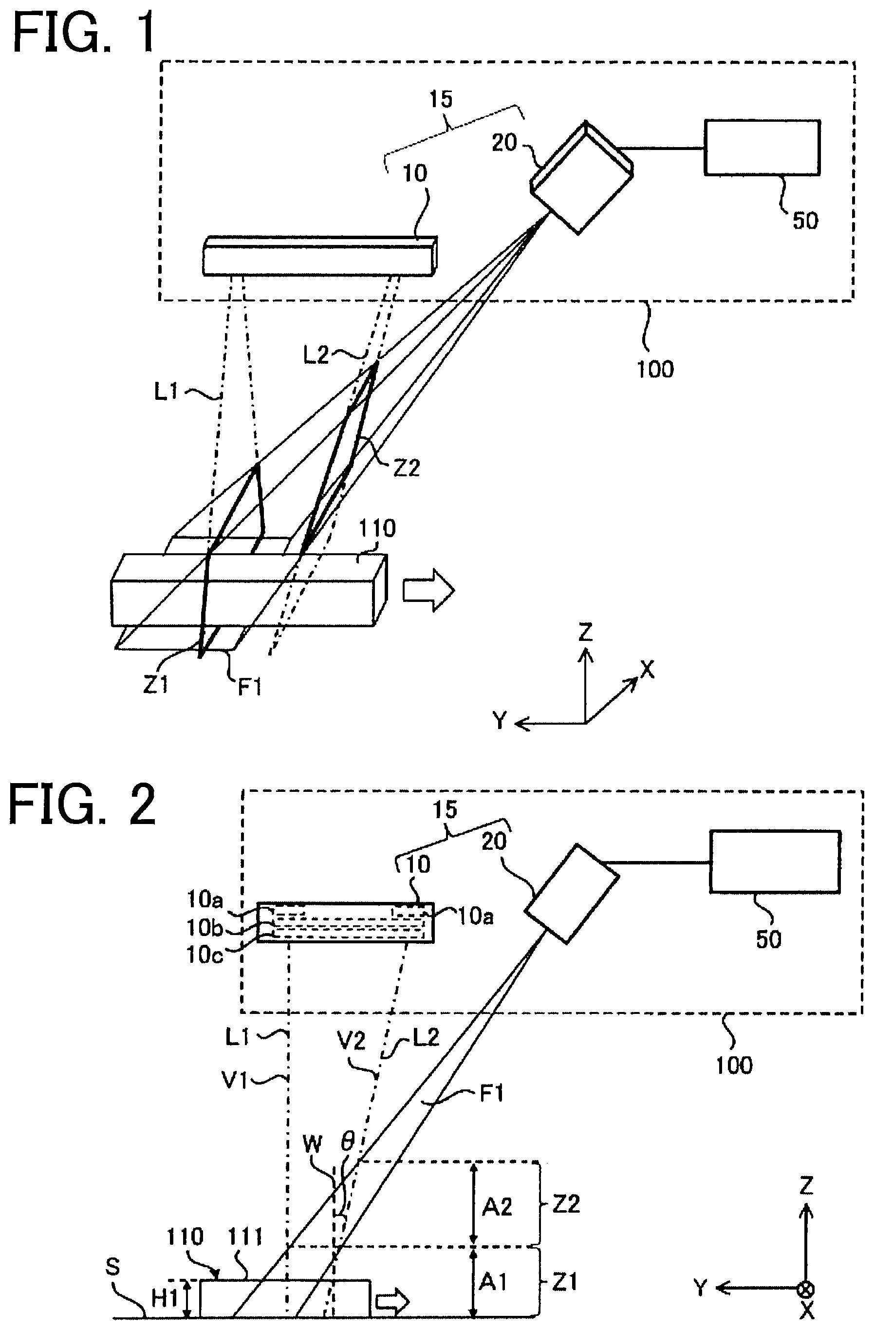
is a perspective view showing a schematic structure of a shape measuring device 100 according to a first embodiment and a first object 110 . is a diagram of the shape measuring device 100 and the first object 110 shown in as seen in an X-axis direction. The first object 110 (hereafter, also referred to as an “object 110 ”) is an example of the measurement object.
The shape measuring device 100 includes a light radiating unit 10 (hereafter, also referred to as a “first light radiating unit 10 ”), an image capturing unit 20 (hereafter, also referred to as a “first image capturing unit 20 ”), and a measuring unit 50 .
The light radiating unit 10 radiates first line light L 1 that is linear light and second line light L 2 that is linear light. In such a manner, the light radiating unit 10 radiates two beams of line light. The first line light L 1 and the second line light L 2 are light that spreads in the X-axis direction. The first line light L 1 and the second line light L 2 are projected on a surface of the first object 110 . Each shape of an image (pattern) of the first line light L 1 and the second line light L 2 is a linear form extending in the X-axis direction. It should be noted that the light radiating unit 10 may radiate three beams of light or more.
The second line light L 2 is projected from a position away from the first line light L 1 in a Y-axis direction that is a predetermined scanning direction. The second line light L 2 is parallel to the first line light L 1 in the X-axis direction. It should be noted that the second line light L 2 is not necessarily parallel to the first line light L 1 in only the X-axis direction and has only to be parallel to the first line light L 1 in predetermined one direction. Also, a light radiating unit that radiates the first line light L 1 and a light radiating unit that radiates the second line light L 2 may be separate units. In addition, a wavelength of the first line light L 1 may be different from a wavelength of the second line light L 2 , and intensity of the first line light L 1 may be different from intensity of the second line light L 2 .
As shown in , the light radiating unit 10 includes, for example, spot light sources 10 a , a collimating lens 10 b , a cylindrical lens 10 c . The collimating lens 10 b collimates light emitted from the spot light sources 10 a . The cylindrical lens 10 c converts a pattern of the light collimated by the collimating lens 10 b to a linear form. Accordingly, the first line light L 1 and the second line light L 2 are formed.
The image capturing unit 20 is, for example, a camera including a complementary metal oxide semiconductor (CMOS) image sensor. The image capturing unit 20 has an field of view F 1 (hereafter, also referred to as a “first field of view F 1 ”). A direction of the field of view F 1 is different from radiation directions of the first line light L 1 and the second line light L 2 radiated from the light radiating unit 10 .
In an example shown in , the image capturing unit 20 captures the first object 110 passing through a first measurement region Z 1 . The first measurement region Z 1 is a region where the first line light L 1 and the field of view F 1 intersect with each other. Specifically, the first measurement region Z 1 is a region where a first plane V 1 through which the first line light L 1 passes and the field of view F 1 intersect with each other. The first plane V 1 is an imaginary X-Z plane. A height H 1 of the first object 110 from the datum plane S is within the first measurement region Z 1 . It should be noted that the first line light L 1 and the second line light L 2 are radiated along the X-Z plane, but the first line light L 1 and the second line light L 2 are sometimes not parallel to the X-Z plane depending on an angle of incidence. For that reason, each of a second plane V 2 , which is described later, through which the second line light L 2 passes and the first plane V 1 is referred to as the “imaginary X-Z plane.”
The image capturing unit 20 obtains an image of a part, which is irradiated with the first line light L 1 , of the first object 110 passing through the first measurement region Z 1 . A part, which is irradiated with the first line light L 1 , of the first object 110 is, for example, a surface 111 (hereafter, also referred to as a “top surface”) facing in the +Z-axis direction of surfaces of the first object 110 .
Also, as shown in A and 5 B referenced later, the image capturing unit 20 captures a second object 120 passing through a second measurement region 22 that is different from the first measurement region Z 1 . The second measurement region Z 2 is a region where the second line light L 2 and the field of view F 1 intersect with each other. Specifically, the second measurement region Z 2 is a region where a second plane V 2 through which the second line light L 2 passes and the field of view F 1 intersect with each other. The second plane V 2 is an imaginary X-Z plane.
The second measurement region Z 2 is located on the light radiating unit 10 side (i.e., +Z axis side) from the first measurement region Z 1 . In the first embodiment, the second measurement region Z 2 is located next to the first measurement region 21 in the Z-axis direction. In addition, the second measurement region Z 2 does not overlap with the first measurement region Z 1 in the Z-axis direction. It should be noted that a part of the second measurement region Z 2 may overlap with the first measurement region Z 1 so long as most of the second measurement region 22 does not overlap with the first measurement region Z 1 . That is, the second measurement region Z 2 has only to include a region that does not overlap with the first measurement region Z 1 .
In the first embodiment, an angle of incidence (e.g., angle θ shown in ) made by the second line light L 2 to a normal W perpendicular to a datum plane S is different from an angle of incidence made by the first line light L 1 . This makes it possible to serve the second measurement region Z 2 as a region that is different from the first measurement region Z 1 . In the first embodiment, the first line light L 1 is incident on the object along the normal W. Therefore, the angle of incidence made by the first line light L 1 incident on the object is zero degrees. In contrast to this, the angle of incidence made by the second line light L 2 incident on the object is an angle θ that is larger than zero degrees. It should be noted that the angle of incidence made by the second line light L 2 may be the same as the angle of incidence made by the first line light L 1 . That is, the second angle of incidence that is the angle of incidence made by the second line light L 2 has only to be equal to or larger than the first angle of incidence that is the angle of incidence made by the first line light L 1 .
In addition, it is possible to serve the second measurement region Z 2 as a region that is different from the first measurement region Z 1 by adjusting a position of the image capturing unit 20 and an optical axis angle of the image capturing unit 20 .
Also, in the first embodiment, a length A 2 of the second measurement region Z 2 in the Z-axis direction is the same as a length A 1 of the first measurement region Z 1 in the Z-axis direction. It should be noted that the length A 1 of the first measurement region Z 1 in the Z-axis direction may be shorter than the length A 2 of the second measurement region Z 2 in the Z-axis direction as shown in referenced later. That is, the length A 1 of the first measurement region Z 1 has only to be equal to or shorter than the length A 2 of the second measurement region Z 2 .
The shape measuring device 100 further includes a moving unit (not shown) that move (carry) the object in the scanning direction (−Y-axis direction in the first embodiment). It should be noted that the moving unit may move an optical system 15 including the light radiating unit 10 and the image capturing unit 20 in the scanning direction with the object stationary. That is, in the first embodiment, the optical system 15 and the object move in the Y-axis direction relatively with each other. Accordingly, images including an image of line light projected on the object are captured by the image capturing unit 20 one by one.
The measuring unit 50 measures a shape of the object on the basis of the image obtained by the image capturing unit 20 . The measuring unit 50 is, for example, a central processing unit (CPU) including a memory. The measuring unit 50 calculates data indicating information as to the height of the object on the basis of the image obtained by the image capturing unit 20 . For example, in the case where the object is the first object 110 having the height H 1 , the measuring unit 50 calculates the height H 1 of the first object 110 on the basis of an image of a part, which is irradiated with the first line light L 1 , of the first object 110 passing through the first measurement region Z 1 .
When the measuring unit 50 calculates the height of the object, the measuring unit 50 needs to determine whether an image of the line light projected on the object is an image of the first line light L 1 or an image of the second line light L 2 . A method for determining with the measuring unit 50 will now be described below. First, with reference to , A , and B , an image captured by the image capturing unit 20 when the first object 110 passes through the first measurement region Z 1 will now be described.
is a diagram of the shape measuring device 100 and the first object 110 at a point in time of a start of measurement as seen in the X-axis direction. An end part on a −Y axis side of the top surface 111 of the first object 110 is irradiated with the first line light L 1 at the point in time of the start of measuring the first object 110 . In the following description, let be time t=0 the point in time of the start of the measurement. After the start of the measurement, the first object 110 moves in the −Y-axis direction, and thus the image capturing unit 20 obtains an image including an image of the first line light L 1 projected on the top surface 111 of the first object 110 .
A and 4 B are diagrams showing an example of a transition of an image captured by the image capturing unit 20 shown in to 3 when the shape measuring device 100 measures the shape of the first object 110 . In order to facilitate the explanation of the images shown in A , B , and A to D referenced later, a Y 1 axis that is a coordinate axis showing the height of the object and a X 1 axis that is another coordinate axis perpendicular to the Y 1 axis are used in the images.
A is a schematic diagram showing an example of an image B 10 obtained when the time t<0. When the time t<0, the first object 110 is not irradiated with the first line light L 1 and the datum plane S is irradiated with the first line light L 1 . Therefore, an image P 10 of the first line light L 1 projected on the datum plane S is shown in the image B 10 . When the time t<0, the datum plane S is irradiated with also the second line light L 2 , but an image of the second line light L 2 is not included in the field of view F 1 . Therefore, the image of the second line light L 2 is not shown in the image B 10 .
B is a schematic diagram showing an example of an image B 11 obtained when the time t≥0. When the time t≥0, the datum plane S and the top surface 111 of the first object 110 are irradiated with the first line light L 1 . Therefore, in addition to the image P 10 , an image P 11 of the first line light L 1 projected on the top surface 111 is shown in the image B 11 . A position of the image P 11 in the Y 1 axis direction in the image B 11 corresponds to the height H 1 of the first object 110 . A distance between the image P 10 and the image P 11 in the Y 1 axis direction is the same as the height H 1 .
When the time t≥0, the datum plane S and the first object 110 are irradiated with the second line light L 2 , but the image of the second line light L 2 is not included in the field of view F 1 . Therefore, the image of the second line light L 2 is not shown in the image B 11 .
Next, images obtained by the image capturing unit 20 when the second object 120 that is higher than the first object 110 passes through the first measurement region Z 1 and the second measurement region 22 will now be described with reference to A , B , and A to 6 D . A is a diagram of the shape measuring device 100 according to the first embodiment and the second object 120 at a point in time of a start of measurement (i.e., time t=0) as seen in the X-axis direction. The second object 120 also moves in the −Y-axis direction as much as the first object 110 .
As shown in A , a height H 2 of the second object 120 from the datum plane S is within the first measurement region Z 1 and the second measurement region Z 2 . The image capturing unit 20 obtains an image of a part, which is irradiated with the first line light L 1 and the second line light L 2 , of the second object 120 when the second object 120 moves in the −Y-axis direction. A part, which is irradiated with the first line light L 1 , of the second object 120 is a top surface 121 of the second object 120 . Also, parts, which are irradiated with the second line light L 2 , of the second object 120 is the top surface 121 and a side surface 122 of the second object 120 . An end part on a −Y axis side of the top surface 121 of the second object 120 is irradiated with the first line light L 1 at the point in time of the start of measuring the second object 120 .
B is a diagram of the shape measuring device 100 according to the first embodiment and the second object 120 passing through the second measurement region Z 2 after the start of the measurement as seen in the X-axis direction. In B , the side surface 122 of the second object 120 is irradiated with the second line light L 2 . In the following description, let be time t 1 the time at which the side surface 122 of the second object 120 is irradiated with the second line light L 2 . As time advances from the time t 1 , a part, which is irradiated with the second line light L 2 , of the second object 120 is shifted from the side surface 122 to the top surface 121 . It should be noted that as long as parameters such as the angle of incidence made by the first line light L 1 , the angle of incidence made by the second line light L 2 , the position of the image capturing unit 20 , and the moving speed of the second object 120 are not changed, the time t 1 is fixed regardless of the height H 2 when the height H 2 of the second object 120 is within the second measurement region Z 2 .
A to 6 D are diagrams showing an example of a transition of an image captured by the image capturing unit 20 shown in A and 5 B when the shape measuring device 100 measures a shape of the second object 120 . A is a schematic diagram showing an example of an image B 20 obtained when the time t<0. When the time t<0, the second object 120 is not irradiated with the first line light L 1 and the datum plane S is irradiated with the first line light L 1 . Therefore, the image P 10 of the first line light L 1 projected on the datum plane S is shown in the image B 20 . When the time t<0, the datum plane S is irradiated with also the second line light L 2 , but the image of the second line light L 2 is not included in the field of view F 1 . Therefore, the image of the second line light L 2 is not shown in the image B 20 .
B is a schematic diagram showing an example of an image B 21 obtained after the start of the measurement before the time t 1 has passed. When the time 0≤t<t 1 , the datum plane S and the top surface 121 are irradiated with the first line light L 1 . An image of the first line light L 1 projected on the top surface 121 is not included in the field of view F 1 . Therefore, the image of the first line light L 1 projected on the top surface 121 of the second object 120 is not shown in the image B 21 , and images P 10 of the first line light L 1 projected on the datum plane S are shown in the image B 21 .
C is a schematic diagram showing an example of an image B 22 captured when the time t=t 1 . As shown in B referenced above, at the time t=t 1 , the datum plane S and the top surface 121 are irradiated with the first line light L 1 and the side surface 122 of the second object 120 is irradiated with the second line light L 2 . At also the time t=t 1 , the image of the first line light L 1 projected on the top surface 121 is not included in the field of view F 1 . Therefore, the image P 10 of the first line light L 1 projected on the datum plane S and the image P 21 of the second line light L 2 projected on the side surface 122 are shown in the image B 22 . The images P 10 and P 21 are shown in an end part on a −Y axis side of the image B 22 .
D is a schematic diagram showing an example of an image B 23 obtained after the time t 1 has passed. When the time t>t 1 , the datum plane S and the top surface 121 are irradiated with the first line light L 1 . In addition, when the time t>t 1 , the top surface 121 is irradiated with the second line light L 2 after the side surface 122 is irradiated with the second line light L 2 for a set time. When also the time t>t 1 , the image of the first line light L 1 projected on the top surface 121 is not included in the field of view F 1 . Therefore, in addition to the image P 10 of the first line light L 1 projected on the datum plane S, an image P 22 of the second line light L 2 projected on the top surface 121 or the side surface 122 is shown in the image B 23 .
As described above, the image B 11 is obtained as a first image including the image P 11 of the first line light L 1 when the first object 110 passes through the first measurement region Z 1 . Also, the image B 22 and the image B 23 are obtained as second images including the images P 21 and P 22 respectively of the second line light L 2 when the second object 120 passes through the first measurement region 21 and the second measurement region Z 2 . That is, the image of the line light included in the image obtained by the image capturing unit 20 is different depending on the height of the object.
Also, the transition of the image obtained by the image capturing unit 20 is different in comparison with the case in which the first object 110 passes through the first measurement region Z 1 when the second object 120 passes through the first measurement region 21 and the second measurement region Z 2 . To be specific, the image B 20 , the image B 21 , the image B 22 , and the image B 23 are captured in this order when the second object 120 passes through the first measurement region Z 1 and the second measurement region Z 2 . Also, the image B 10 and the image B 11 are captured in this order when the first object 110 passes through the first measurement region Z 1 .
In such a manner, the image of the line light included in the image obtained by the image capturing unit 20 and the transition of the image are different depending on the height of the object and consequently the measuring unit 50 is able to determine whether the image of the line light projected on the object is the image of the first line light L 1 or the image of the second line light L 2 .
Advantages of First Embodiment
According to the first embodiment described above, the image capturing unit 20 of the shape measuring device 100 captures the first object 110 passes through the first measurement region Z 1 and captures the second object 120 passes through the second measurement region Z 2 . The measuring unit 50 measures the shape of the first object 110 on the basis of the first image B 11 of a part, which is irradiated with the first line light L 1 , of the first object 110 . In addition, the measuring unit 50 measures the shape of the second object 120 on the basis of the second images B 22 and B 23 of parts, which are irradiated with the second line light L 2 , of the second object 120 . Accordingly, with one image capturing unit 20 , the shape measuring device 100 is able to extend a range of measurement in a direction along the height of the object and to measure the object with high accuracy. Therefore, it is possible to provide the shape measuring device 100 that extends the range of measurement at low cost and measures the object with high accuracy.
Also, according to the first embodiment, one image capturing unit 20 has a plurality of measurement regions (i.e., first measurement region Z 1 and second measurement region Z 2 ) depending on the height of the object. Accordingly, whether the shape of the object passing through the first measurement region Z 1 is measured or the shape of the object passing through the second measurement region Z 2 is measured, the number of pixels of an image on which arithmetic processing is performed by the measuring unit 50 is the same. Therefore, it is possible to reduce the load on calculations and speed up the calculation processing in the measuring unit 50 .
Also, according to the first embodiment, synchronous control of images obtained by two image capturing units is not required in comparison with a configuration including the two image capturing units in a shape measuring device. Hence, it is possible to provide the simplified shape measuring device 100 . Therefore, according to the first embodiment, it is possible to provide the shape measuring device 100 that is simplified and can reduce the load on calculations at low cost.
Second Embodiment
is a diagram of a shape measuring device according to a second embodiment and the object 110 as seen in the X-axis direction. In , each component identical or corresponding to a component shown in is assigned the same reference character as those in . The shape measuring device 200 according to the second embodiment is different from the shape measuring device 100 according to the first embodiment in that a length A 22 of a second measurement region Z 22 in the Z-axis direction is different from a length A 21 of a first measurement region Z 21 in the Z-axis direction. With respect to the other points, the shape measuring device 200 according to the second embodiment is the same as the shape measuring device 100 according to the first embodiment.
As shown in , the shape measuring device 200 includes the light radiating unit 10 , an image capturing unit 220 , and the measuring unit 50 .
The image capturing unit 220 captures the first object 110 passing through the first measurement region Z 21 and the second measurement region Z 22 . The first measurement region Z 21 is a region where the first plane V 1 through which the first line light L 1 passes and the field of view F 1 of the image capturing unit 220 intersect with each other. Also, the second measurement region Z 22 is a region where the second plane V 2 through which the second line light L 2 passes and the field of view F 1 of the image capturing unit 220 intersect with each other.
In the second embodiment, the length A 22 of the second measurement region Z 22 in the Z-axis direction is different from the length A 21 of the first measurement region Z 21 in the Z-axis direction. Accordingly, it is possible to vary resolving power in the second measurement region Z 22 with respect to resolving power in the first measurement region Z 21 . In an example shown in , the length A 21 is shorter than the length A 22 . The resolving power in each of the first measurement region Z 21 and the second measurement region Z 22 is the value obtained by dividing the field of view by the number of pixels. In the second embodiment, the number of pixels in the case in which the object 110 passing through the first measurement region Z 21 is captured is the same as the number of pixels in the case in which the object 110 passing through the second measurement region Z 22 is captured. For that reason, when the length A 21 is shorter than the length A 22 , the value of the resolving power in the first measurement region Z 21 is smaller than the value of the resolving power in the second measurement region Z 22 . This makes it possible to enhance the resolving power in the first measurement region Z 21 with respect to the resolving power in the second measurement region Z 22 .
Adjusting at least one of the angle of incidence made by the first line light L 1 , the angle of incidence made by the second line light L 2 , a position of the image capturing unit 220 , or an optical axis angle of the image capturing unit 220 can shorten the length A 21 than the length A 22 . It should be noted that the length A 22 may be shorter than the length A 21 . That is, either the length A 21 or the length A 22 has only to be shorter than the other. It should be noted that when the length A 21 is different from the length A 22 , as in the second embodiment, a focal point of the image capturing unit 20 is preferable to be within the range of the measurement region having the shortest length in the Z-axis direction, of the first measurement region Z 21 and the second measurement region Z 22 .
Advantages of Second Embodiment
According to the second embodiment described above, the length A 22 of the second measurement region Z 22 in the Z-axis direction is different from the length A 21 of the first measurement region Z 21 in the Z-axis direction. Accordingly, it is possible to vary the resolving power in the first measurement region Z 21 with respect to the resolving power in the second measurement region Z 22 .
The length A 21 of the first measurement region Z 21 in the Z-axis direction is shorter than the length A 22 of the second measurement region Z 22 in the Z-axis direction. Accordingly, it is possible to enhance the resolving power in the first measurement region Z 21 with respect to the resolving power in the second measurement region Z 22 .
Third Embodiment
is a diagram of a shape measuring device 300 according to a third embodiment and the object 110 as seen in the X-axis direction. In , each component identical or corresponding to a component shown in is assigned the same reference character as those in . The shape measuring device 300 according to the third embodiment is different from the shape measuring device 100 according to the first embodiment in that a focal point G 1 of a first line light L 31 is within the range of the first measurement region Z 1 and a focal point G 2 of a second line light L 32 is within the range of the second measurement region Z 12 . With respect to the other points, the shape measuring device 300 according to the third embodiment is the same as the shape measuring device 100 according to the first embodiment.
As shown in , the shape measuring device 300 includes a light radiating unit 310 , the image capturing unit 20 , and the measuring unit 50 .
The light radiating unit 310 includes a collimating lens and a cylindrical lens (e.g., collimating lens 10 b and cylindrical lens 10 c shown in referenced above). The arrangements of the collimating lens and the cylindrical lens are coordinated. The collimating lens collimates the light emitted from a spot light source. The cylindrical lens condenses a pattern of the light collimated by the collimating lens into a linear form. The light radiating unit 310 radiates the first line light L 31 that is linear light and the second line light L 32 that is linear light. Each of the first line light L 31 and the second line light L 32 spreads in the Y-axis direction. In an example shown in , a width of the first line light L 31 in the Y-axis direction is expressed as w 1 , and a width of the second line light L 32 in the Y-axis direction is expressed as w 2 .
In the third embodiment, the focal point G 1 of the first line light L 31 , which is the position where the width w 1 is the thinnest, is included within the first measurement region Z 1 . Accordingly, when the object 110 passes through the first measurement region Z 1 , the object 110 is irradiated with the condensed first line light L 31 . Therefore, the positional accuracy of the image of the first line light L 31 projected on the object 110 is improved and consequently it is possible to improve the accuracy of calculating the height H 1 of the object 110 in the measuring unit 50 .
Also, the focal point G 2 of the second line light L 32 , which is the position where the width w 2 is the thinnest, is included within the second measurement region Z 2 . Accordingly, when the object passes through the second measurement region Z 2 , the object is irradiated with the condensed second line light L 32 . Therefore, the positional accuracy of the image of the second line light L 32 projected on the object passing through the second measurement region Z 2 is improved and consequently it is possible to improve the accuracy of calculating the height of the object in the measuring unit 50 .
For example, by adjusting the position in the Z-axis direction of the collimating lens (not shown) included in the light radiating unit 310 to a predetermined position, the focal point G 1 can be included in the first measurement region Z 1 and the focal point G 2 can be included in the second measurement region Z 2 .
Advantages of Third Embodiment
According to the third embodiment described above, the focal point G 1 of the first line light L 31 is included in the first measurement region Z 1 . Accordingly, when the object 110 passes through the first measurement region Z 1 , it is possible to improve the accuracy of calculating the height H 1 of the object 110 in the measuring unit 50 .
Also, according to third embodiment, the focal point G 2 of the second line light L 2 is included in the second measurement region Z 2 . Accordingly, when the object passes through the second measurement region Z 2 , it is possible to improve the accuracy of calculating the height of the object in the measuring unit 50 .
Fourth Embodiment
is a diagram of a shape measuring device 400 according to a fourth embodiment and an object 130 as seen in the X-axis direction. In , each component identical or corresponding to a component shown in is assigned the same reference character as those in . The shape measuring device 400 according to the fourth embodiment is different from the shape measuring device 100 according to the first embodiment in that the shape measuring device 400 further includes a second light radiating unit 30 and a second image capturing unit 40 . With respect to the other points, the shape measuring device 400 according to the fourth embodiment is the same as the shape measuring device 100 according to the first embodiment.
The object 130 shown in is an example of an object to be measured. The shape of the object 130 is different from the shape of each of the first object 110 and the second object 120 of the first embodiment. In an example shown in , the shape of the object 130 as seen in the X-axis direction is a trapezoid. In other words, in the fourth embodiment, side surfaces 132 and 133 facing in the Y-axis direction of the object 130 are inclined surfaces. When the shape measuring device 100 (see, for example, and ) according to the first embodiment measures the shape of the object 130 , the first image capturing unit 20 is able to capture a pattern of line light projected on the side surface 132 facing in the −Y-axis direction. However, depending on the degree of the incline of the side surface 133 facing in the +Y-axis direction, the first image capturing unit 20 cannot capture the pattern of the line light projected on the side surface 133 . Thus, depending on the shape of the object 130 , a blind spot (e.g., side surface 133 facing in the +Y-axis direction) that cannot be captured by the first image capturing unit 20 may occur. The shape measuring device 400 includes the first light radiating unit 10 , the first image capturing unit 20 , the second light radiating unit 30 , the second image capturing unit 40 , and the measuring unit 50 .
The second light radiating unit 30 radiates third line light L 3 that is linear light and fourth line light L 4 that is linear light. Each of the third line light L 3 and the fourth line light L 4 is light that spreads in the X-axis direction. The third line light L 3 and the fourth line light L 4 are projected on the surface of the object 130 . The shape of image of each of the third line light L 3 and the fourth line light L 4 projected on the surface of the object 130 is a linear form extending in the X-axis direction.
The fourth line light L 4 is radiated from a position away from the third line light L 3 in the Y-axis direction, which is a scanning direction. The fourth line light L 4 is parallel to the third line light L 3 in the X-axis direction. It should be noted that the fourth line light L 4 is not necessarily parallel to the third line light L 3 in only the X-axis direction and has only to be parallel to the third line light L 3 in predetermined one direction.
The second light radiating unit 30 is disposed on the +Y-axis side from the first light radiating unit 10 . A radiation direction of the third line light L 3 and a radiation direction of the fourth line light L 4 are different from a radiation direction of the first line light L 1 and a radiation direction of the second line light L 2 . The side surface 133 facing in the +Y-axis direction, which cannot be captured by the first image capturing unit 20 , of the object 130 , is irradiated with the third line light L 3 and the fourth line light L 4 .
The second image capturing unit 40 includes a second field of view F 2 that is different from the first field of view F 1 . A direction of the second field of view F 2 is different from radiation directions of the third line light L 3 and the fourth line light L 4 radiated from the second light radiating unit 30 . The second image capturing unit 40 is, for example, a camera including a CCD image sensor. The second image capturing unit 40 captures the object 130 passing through the third measurement region Z 3 . The third measurement region Z 3 is a region where a third plane V 3 through which the third line light L 3 passes and the second field of view F 2 intersect with each other. The third plane V 3 is an imaginary X-Z plane. In an example shown in , a height H 3 of the object 130 from the datum plane S is within the third measurement region 23 and the first measurement region Z 1 . It should be noted that the third line light L 3 and the fourth line light L 4 are sometimes not parallel to the X-Z plane depending on the angles of incidence, but the third line light L 3 and the fourth line light L 4 are radiated along the X-Z plane. For that reason, each of the third plane V 3 and the fourth plane V 4 through which the fourth line light L 4 described later passes is referred to as an “imaginary X-Z plane.”
In addition, the second image capturing unit 40 captures the object passing through the fourth measurement region Z 4 that is different from the third measurement region Z 3 . The fourth measurement region Z 4 is a region where the fourth plane V 4 through which the fourth line light L 4 passes and the second field of view F 2 intersect with each other. The fourth plane V 4 is an imaginary X-Z plane.
The fourth measurement region Z 4 is disposed on the second light radiating unit 30 side (i.e., on the +Z-axis side) from the third measurement region Z 3 . The fourth measurement region Z 4 is located next to the third measurement region Z 3 in the Z-axis direction. In addition, the fourth measurement region Z 4 does not overlap with the third measurement region Z 3 in the Z-axis direction. It should be noted that a part of the fourth measurement region Z 4 may overlap with the third measurement region Z 3 so long as most of the fourth measurement region Z 4 does not overlap with the third measurement region Z 3 . That is, the fourth measurement region 24 has only to include a region that does not overlap with the third measurement region Z 3 .
An angle of incidence made by the fourth line light L 4 is different from an angle of incidence made by the third line light L 3 . This makes it possible to serve the fourth measurement region Z 4 as a region that is different from the third measurement region 23 . In the fourth embodiment, the fourth line light L 4 is incident on the object 130 along a normal perpendicular to the datum plane S. Therefore, the angle of incidence made by the fourth line light L 4 is zero degrees. In contrast to this, the angle of incidence made by the third line light L 3 is larger than zero degrees. It should be noted that the angle of incidence made by the fourth line light L 4 may be the same as the angle of incidence made by the third line light L 3 .
Also, it is possible to serve the fourth measurement region Z 4 as a region that is different from the third measurement region Z 3 by adjusting a position of the second image capturing unit 40 and an optical axis angle of the second image capturing unit 40 . Also, the optical axis of the second image capturing unit 40 is located across from the optical axis of the first image capturing unit 20 with the center line C, which is perpendicular to the datum plane S, that passes through the center in the Y-axis direction of the object 130 in between. In other words, the second image capturing unit 40 is disposed across from the first image capturing unit 20 with the first light radiating unit 10 and the second light radiating unit 30 in between in the Y-axis direction.
The measuring unit 50 measures the shape of the object 130 on the basis of an image including an image of the line light obtained by the first image capturing unit 20 and an image including an image of the line light obtained by the second image capturing unit 40 .
When the height H 3 of the object 130 is within the first measurement region Z 1 and the third measurement region 3 , the measuring unit 50 measures the shape of the object 130 on the basis of a first image that is an image of a region 131 a that is a part, which is irradiated with the line light L 1 , of the top surface 131 of the object 130 and a third image that is an image of a region 131 b that is a part, which is irradiated with the third line light L 3 , of the top surface 131 . Accordingly, the shape of the object 130 can be measured on the basis of the third image obtained by the second image capturing unit 40 for the region 131 b , which is a blind spot from the first image capturing unit 20 , of the object 130 .
When the height H 3 of the object 130 is within the second measurement region Z 2 and the fourth measurement region Z 4 , the measuring unit 50 measures the shape of the object 130 on the basis of second images that are images of parts, which are irradiated with the second line light L 2 , of the object 130 and a fourth image that is an image of a part, which is irradiated with the fourth line light L 4 .
The image obtained by the first image capturing unit 20 and the image obtained by the second image capturing unit 40 are sometimes in common with each other. In this case, the measuring unit 50 calculates data indicating height information of the object 130 on the basis of both of the image obtained by the first image capturing unit 20 and the image obtained by the second image capturing unit 40 . It should be noted that the measuring unit 50 may calculate the data described above on the basis of either the image obtained by the first image capturing unit 20 or the image obtained by the second image capturing unit 40 .
Advantage of Fourth Embodiment
According to the fourth embodiment described above, the shape measuring device 400 includes the second light radiating unit 30 and the second image capturing unit 40 . Accordingly, it is possible to measure the shape of the region of the object 130 that is a blind spot (specifically, side surface 133 facing in the +Y-axis direction) of the first image capturing unit 20 , that is, an occlusion portion of the object 130 .
DESCRIPTION OF REFERENCE CHARACTERS
10 first light radiating unit, 20 , 220 first image capturing unit, 30 second light radiating unit, 40 second image capturing unit, 50 measuring unit, 100 , 200 , 300 , 400 shape measuring device, 110 , 120 , 130 object, A 1 , A 2 , A 3 , A 4 , A 21 , A 22 length, B 10 , B 11 , B 20 , B 21 , B 22 , B 23 image, F 1 first field of view, F 2 second field of view, G 1 , G 2 focal point, L 1 , L 31 first line light, L 2 , L 32 second line light, L 3 third line light, L 4 fourth line light, V 1 first plane, V 2 second plane, V 3 third plane, V 4 fourth plane, Z 1 , Z 21 first measurement region, Z 2 , Z 22 second measurement region.
Figures (6)
Citations
This patent cites (11)
- US7876455
- US2008/0170238
- US2018/0308282
- US2020/0134860
- US2020/0300616
- USH08-118023
- US2001-304827
- US2008-175625
- US2015-114235
- US2020-153718
- USWO-2017064875