System and Method for Natural Gas Liquid Production with Flexible Ethane Recovery or Rejection
Abstract
A system and method for processing an NGL product stream from a natural gas feed stream in either an ethane retention or ethane rejection mode utilizing heat exchange of particular process streams. In ethane rejection mode, there are preferably two stages of heat exchange between the feed stream and a first separator bottoms stream and a side stream withdrawn from a fractionation tower is cooled through heat exchange with both the fractionation tower and second separator overhead streams, and optionally with an external refrigerant, resulting in 5-15% ethane and at least 97% propane recovery. In ethane retention mode, a portion of the feed stream and portions of a first separator overhead and bottoms streams are preferably separately cooled through heat exchange with other process streams, including the entireties of a recycled residue gas and fractionation column overhead streams, resulting in around 99% ethane and around 100% propane recovery.
Claims (18)
1 . A method for processing a feed stream comprising methane, ethane, propane, and other components using a single fractionation column in an ethane retention mode to produce an NGL product stream and a residue gas stream, the method comprising: splitting the feed stream into two portions, a first portion having 40% to 75% of a molar flow rate of the feed stream and a second portion having a balance of the molar flow rate of the feed stream; combining the first portion of the feed stream and the second portion of the feed stream to form a combined feed stream; separating the combined feed stream in a first separator into a first overhead stream and a first bottoms stream; splitting the first overhead stream into a first portion and a second portion; splitting the first bottoms stream into a first portion and a second portion; separating the first portion of the first overhead stream, the second portion of the first overhead stream, the first portion of the first bottoms stream, the second portion of the first bottoms stream, and a recycled stream in the single fractionation column into a second overhead stream, a side stream, and a second bottoms stream; exchanging heat in a first heat exchanger by simultaneously passing each of the first portion of the feed stream, the recycled stream, an entirety of the second overhead stream, and the side stream through the first heat exchanger; exchanging heat in a second heat exchanger by simultaneously passing each of the entirety of the second overhead stream, the recycled stream, the first portion of the first bottoms stream, and the first portion of the first overhead stream through the second heat exchanger; cooling the second portion of the feed stream in a tube side of a reboiler of the single fractionation column, prior to the combining the second portion of the feed stream with the first portion of the feed stream, by heat exchange with the second bottoms stream; and reboiling the second bottoms stream on a shell side of the reboiler of the single fractionation column to produce a vapor stream and the NGL product stream; compressing the entirety of the second overhead stream after passing through the first heat exchanger; wherein in the first heat exchanger: (1) the first portion of the feed stream is cooled prior to the combining with the second portion of the feed stream, (2) the recycled stream is cooled prior to passing through the second heat exchanger, (3) the entirety of the second overhead stream is warmed after passing through the second heat exchanger, and (4) the side stream withdrawn from the single fractionation column is warmed prior to returning to the single fractionation column; wherein in the second heat exchanger: (1) the entirety of the second overhead stream is warmed prior to passing through the first heat exchanger, (2) the recycled stream is cooled after passing through the first heat exchanger and prior to the single fractionation column, (3) the first portion of the first bottoms stream is cooled prior to the single fractionation column, and (4) the first portion of the first overhead stream is cooled prior to the single fractionation column; wherein the residue gas stream comprises the second overhead stream after the compressing; wherein the side stream is the only side stream withdrawn from the single fractionation column for heat exchange with any portion of the feed stream, and the side stream exchanges heat with the first portion of the feed stream in the first heat exchanger and the side stream does not exchange heat with the second portion of the feed stream; wherein no portion of the first bottoms stream exchanges heat with the first portion of the feed stream; and wherein no portion of the first bottoms stream exchanges heat with the second portion of the feed stream; wherein the recycled stream is a portion of the residue gas stream; wherein the NGL product stream comprises greater than 98% of the ethane from the feed stream; and wherein the other components comprise 0.14% or less CO 2 .
11 . A method for processing a feed stream comprising methane, ethane, propane, and other components using a single fractionation column in an ethane retention mode to produce an NGL product stream and a residue gas stream, the method comprising: splitting the feed stream into two portions, a first portion and a second portion, wherein the second portion has 25% to 65% of a molar flow rate of the feed stream; combining the first portion of the feed stream and the second portion of the feed stream to form a combined feed stream; separating the combined feed stream in a first separator into a first overhead stream and a first bottoms stream; splitting the first overhead stream into a first portion and a second portion; splitting the first bottoms stream into a first portion and a second portion; separating the first portion of the first overhead stream, the second portion of the first overhead stream, the first portion of the first bottoms stream, the second portion of the first bottoms stream, and a recycled stream in the single fractionation column into a second overhead stream and a second bottoms stream; exchanging heat in a first heat exchanger by simultaneously passing each of a first set of streams through the first heat exchanger; exchanging heat in a second heat exchanger by simultaneously passing each of a second set of streams through the second heat exchanger; cooling the second portion of the feed stream in a tube side of a reboiler of the single fractionation column, prior to the combining the second portion of the feed stream with the first portion of the feed stream, by heat exchange with the second bottoms stream; and reboiling the second bottoms stream on a shell side of the reboiler of the single fractionation column to produce a vapor stream and the NGL product stream; compressing an entirety of the second overhead stream after passing through the first heat exchanger; wherein in the first set of streams in the first heat exchanger consists of: (1) the first portion of the feed stream, which is cooled prior to the combining with the second portion of the feed stream, (2) the recycled stream, which is cooled prior to passing through the second heat exchanger, (3) the entirety of the second overhead stream, which is warmed after passing through the second heat exchanger, and (4) a single side stream withdrawn from the single fractionation column, which is warmed prior to returning to the single fractionation column; wherein in the second set of streams in the second heat exchanger consists of: (1) the entirety of the second overhead stream, which is warmed prior to passing through the first heat exchanger, (2) the recycled stream, which is cooled after passing through the first heat exchanger and prior to the single fractionation column, (3) the first portion of the first bottoms stream, which is cooled prior to the single fractionation column, and (4) the first portion of the first overhead stream, which is cooled prior to the single fractionation column; wherein the residue gas stream comprises the second overhead stream after the compressing; wherein no portion of the first bottoms stream exchanges heat with the first portion of the feed stream; and wherein no portion of the first bottoms stream exchanges heat with the second portion of the feed stream; wherein the recycled stream is a portion of the residue gas stream; wherein greater than 98% of the ethane from the feed stream is in the NGL product stream; and wherein the other components comprise 0.14% or less CO 2 .
Show 16 dependent claims
2 . The method of claim 1 further comprising combining the first portion of the first bottoms stream and the first portion of the first overhead stream prior to passing the first portion of the first bottoms stream and the first portion of the first overhead stream to the second heat exchanger; wherein the NGL product stream comprises 99% to less than 100% of the ethane from the feed stream.
3 . The method of claim 2 further comprising after cooling the second portion of the feed stream in the tube side of the reboiler, supplying external refrigerant to a third heat exchanger to cool in the third heat exchanger the second portion of the feed stream prior to combining the second portion of the feed stream with the first portion of the feed stream.
4 . The method of claim 1 wherein there is no heat exchange between only the second overhead stream and the recycled stream.
5 . The method of claim 4 wherein the NGL product stream comprises at least 98.64% but less than 100% of the ethane from the feed stream.
6 . The method of claim 4 wherein the feed stream comprises 15% ethane and the NGL product stream comprises at least 99% but less than 100% of the ethane from the feed stream.
7 . The method of claim 1 wherein the first heat exchanger consists of a single heat exchanger for heat exchange between the first portion of the feed stream, the recycled stream, the entirety of the second overhead stream, and the side stream passing through the first heat exchanger.
8 . The method of claim 7 wherein the second heat exchanger consists of a single heat exchanger for heat exchange between the entirety of the second overhead stream, the recycled stream, the first portion of the first bottoms stream, and the first portion of the first overhead stream passing through the second heat exchanger.
9 . The method of claim 8 further comprising combining the first portion of the first bottoms stream and the first portion of the first overhead stream prior to the passing the first portion of the first bottoms stream and the first portion of the first overhead stream to the second heat exchanger; and wherein no external refrigerant is supplied to the first heat exchanger.
10 . The method of claim 1 wherein the other components in the feed stream comprise nitrogen and wherein the NGL product stream comprises 98.64% to 99% of the ethane from the feed stream.
12 . The method of claim 11 wherein 99% or more of the ethane from the feed stream is in the NGL product stream.
13 . The method of claim 1 wherein the NGL product stream comprises at least 99% of the ethane from the feed stream.
14 . The method of claim 1 wherein no portion of the NGL product stream exchanges heat with any portion of the feed stream.
15 . The method of claim 2 wherein no portion of the NGL product stream exchanges heat with any portion of the feed stream.
16 . The method of claim 11 wherein no portion of the NGL product stream exchanges heat with any portion of the feed stream.
17 . The method of claim 2 wherein no portion of the NGL product stream passes through the first heat exchanger; wherein no portion of the NGL product stream passes through the second heat exchanger.
18 . The method of claim 11 wherein no portion of the NGL product stream passes through the first heat exchanger; wherein no portion of the NGL product stream passes through the second heat exchanger.
Full Description
Show full text →
BACKGROUND OF THE INVENTION
1. Field of the Invention
This invention relates to a system and method for separation of natural gas liquid (NGL) components from raw natural gas streams that may be operated in ethane recovery or ethane rejection modes, or utilizing certain common equipment and some process flow and operating modifications is capable of being switched between recovery and rejection modes as desired.
2. Description of Related Art
Various NGL extraction techniques are known in the prior art with differing equipment and/or operational requirements depending on whether the operator wants to recover or reject ethane in the NGL product stream. The economics associated with ethane in NGL product streams have varied over time and by geographic location. Most facilities in operation today operate in rejection mode because an operator could lose up to $0.10 for each gallon of ethane in the NGL product stream. This adds up to significant revenue loss, making it desirable to improve upon rejection methods to reduce the amount of ethane in the NGL product stream. For other facilities, or if the economics of ethane change, it may be desirable to operate in recovery mode.
A prior art system and method for rejecting ethane are described in U.S. Pat. No. 5,799,507. The '507 patent allows for very little ethane in the NGL product stream and around 94% propane recovery in the NGL product stream. The '507 patent utilizes two separators and one fractionation column, compared to two fractionation columns in other prior art rejection systems. The '507 patent is able to reduce the equipment requirements by withdrawing a side stream from the fractionation column, cooling it through heat exchange with the fractionation column overhead stream, and then using it as the feed stream for the second separator.
A prior art system and method for ethane recovery are described in U.S. Pat. No. 6,182,469. The '469 patent utilizes one separator, one absorber tower and one stripper tower, with a modified reboiler system where a portion of the down-flowing liquid from the stripper tower is withdrawn and warmed through heat exchange with the inlet feed stream before being returned to a lower stage than from which it was withdrawn, to achieve around 84% ethane recovery in the NGL product stream. The '469 patent also discloses an ethane recovery system using a residue gas recycle stream with one separator and one tower (similar to U.S. Pat. No. 5,568,737 described below), but does not indicate the amount of ethane recovery achievable with that configuration.
Another prior art system and method that allows for operation in either ethane recovery mode (as shown in ) or ethane rejection mode (as shown in ) is described in U.S. Pat. No. 5,568,737. The 737 patent allow use of the same primary equipment (one separator and one fractionation tower) for either mode with some changes in process stream flows and operating conditions. Ethane recovery mode, which can recover 97-98% of the ethane from the feed stream, requires more heat exchangers than rejection mode. Rejection mode can achieve molar ratios of 0.025:1 ethane to propane.
There is still a need for a system and method that can more efficiently reject or recover ethane in the NGL product stream, reduce energy and equipment requirements, and that is capable of operating in either mode with slight modifications to the process flows and operating conditions.
SUMMARY OF THE INVENTION
Systems and methods disclosed herein facilitate the economically efficient rejection or retention of ethane in NGL product streams, depending on the applicable limits on the amount of ethane acceptable in the NGL product and the economics of ethane recovery, which fluctuate over time and by geographic location, and maximize recovery of propane and heavier hydrocarbons in the NGL product stream. Ethane retention (or recovery) mode refers to processing natural gas stream to maximize the amount of ethane recovered from the feed stream in the NGL product stream, while still maximizing the amount of propane and heavier hydrocarbons in the NGL product stream. Ethane rejection mode refers to processing natural gas stream to minimize the amount of ethane recovered from the feed stream in the NGL product stream, while still maximizing the amount of propane and heavier hydrocarbons in the NGL product stream.
In ethane rejection mode, a typical prior art system and method will primarily include two separators, a pump, a fractionation tower, and at least two primary heat exchangers. Although prior art systems without the second separator can operate in ethane rejection mode, they are less efficient and result in higher amounts of ethane in the NGL product stream. The two separator prior art systems, such as in U.S. Pat. No. 5,799,507, typically involve cooling a natural gas feed stream prior to feeding the first separator through heat exchange with a first separator bottoms stream and a pre-combined fractionating tower overhead stream and second separator overhead stream. The first separator overhead and bottoms streams are feed streams into the fractionation tower. The second separator bottoms stream is another feed stream into the fractionation tower. The fractionation tower bottoms stream is the NGL product stream. The fractionation tower and second separator overhead streams are the residue gas product stream (containing primarily methane). A side stream is also withdrawn from a mid-point in the fractionation tower, which is cooled by heat exchange with the tower overhead stream (upstream of heat exchange with the feed stream and upstream of combining the tower overhead and second separator overhead stream), prior to feeding into the second separator.
According to one preferred embodiment of the invention, a preferred system and method modify prior art systems and methods for operating in ethane rejection mode by altering the heat exchange systems used in the prior art to increase propane recovery, minimize ethane recovery to less than 15% and more preferably less than 10%. Most preferably, the feed stream under goes heat exchange with a first separator bottoms stream and a pre-combined fractionating tower overhead stream and second separator overhead stream in a first heat exchanger prior to feeding the first separator, as in the prior art; however, there are several preferred differences. First, there are preferably two heat exchanges between the feed stream and the first separator bottoms stream, the second being in a second heat exchanger downstream (relative to the feed stream) from the first heat exchanger. Second, the first separator bottoms stream is preferably expanded through an expansion valve, cooling it prior to passing through the second heat exchanger. Third, the feed stream is first split upstream of the first heat exchanger increase the efficiency of heat transfer.
According to another preferred embodiment of the invention for operating in ethane rejection mode by altering the heat exchange systems used in the prior art, a side stream withdrawn from a midpoint in the fractionation tower passes through a third heat exchanger prior to feeding into the second separator. The side stream is cooled through heat exchange with a combined fractionation tower overhead stream and second separator overhead stream, upstream of this combined stream passing through the first heat exchanger. According to yet another preferred embodiment of the invention for operating in ethane rejection mode by altering the heat exchange systems used in the prior art, the side stream withdrawn from the fractionation tower is cooled with an external refrigeration heat exchanger upstream of the third heat exchanger. According to yet another preferred embodiment of the invention, an additional side stream is withdrawn from a midpoint on the fractionation tower and passes through the first heat exchanger to warm the stream before returning to the fractionation tower at a lower tray location than its withdrawal point.
In ethane retention mode, a typical prior art system and method will primarily include one separator, a fractionation tower, a recycled portion of the residue gas stream, and multiple primary heat exchangers. These prior art systems, such as in U.S. Pat. No. 5,568,737, typically involve cooling a natural gas feed stream through heat exchange with a portion of the fractionating tower overhead stream and at least two side streams withdrawn from a lower portion of the fractionation tower, which are returned to the tower at a tray location lower than the withdrawal location in a modified reboiler scheme. After cooling, the feed stream feeds into the separator. The separator overhead and bottoms streams are feed streams into the fractionation tower. Part of the separator overhead and bottoms streams undergo heat exchange with the fractionation tower overhead stream (upstream of heat exchange with the feed stream) and with the recycled portion of the residue gas stream upstream of feeding the fractionation tower. The recycled portion of the residue gas stream also undergoes heat exchange with the other portion of the fractionation tower overhead stream (that part that does not undergo heat exchange with the feed stream) downstream of heat exchange with the separator streams. After the two heat exchanges, the recycled portion of the residue gas stream also feeds into the top of the fractionation tower.
According to one preferred embodiment of the invention, a preferred system and method modify prior art systems and methods for operating in ethane retention mode by altering the heat exchange systems used in the prior art to increase propane recovery, maximize ethane recovery to greater than 98% with propane recovery preferably greater than 99.9%. Most preferably, the feed stream under goes heat exchange with a fractionating tower overhead stream and a side stream withdrawn from the bottom portion of the fractionation tower, similar to the prior art; however, there are several preferred differences. First, the feed stream is first split upstream of the first heat exchanger, with a first portion of the feed stream passing through the first heat exchanger and a second portion passing through a heat exchanger acting as a reboiler for the fractionation column and then through an external refrigeration heat exchanger. The two portions are recombined prior to feeding into the separator. Second, the entire fractionation column overhead stream passes through the first heat exchanger. Third, the recycled portion of the residue gas stream also passes through the first heat exchanger.
According to another preferred embodiment, preferred systems of the invention for operating in ethane rejection or retention mode can built as a single system or as stand-alone systems. As a single system, certain equipment (such as the second separator and pump) would be used or bypassed and other process flow modifications would be made if it is desired to operate in one mode vs. the other mode, as will be understood by those of ordinary skill in the art Additionally, an existing system according to a preferred embodiment of the invention or the prior art for operating in ethane rejection or retention mode could easily be modified and adapted to switch to the other mode, if desired, by making process flow modifications and adding or bypassing certain equipment.
Preferred systems and methods of the invention are useful in either maximizing or minimizing ethane recovery, as desired, while also maximizing recovery of propane and heavier constituents. Through efficient use of heat exchange systems, capital costs and operating costs are reduced. Through efficient use of components common between ethane rejection and retention modes, the systems are flexible in allowing modification and adaption to different operating modes as needs change.
BRIEF DESCRIPTION OF THE DRAWINGS
Systems and methods of preferred embodiments of the invention are further described and explained in relation to the following drawings wherein:
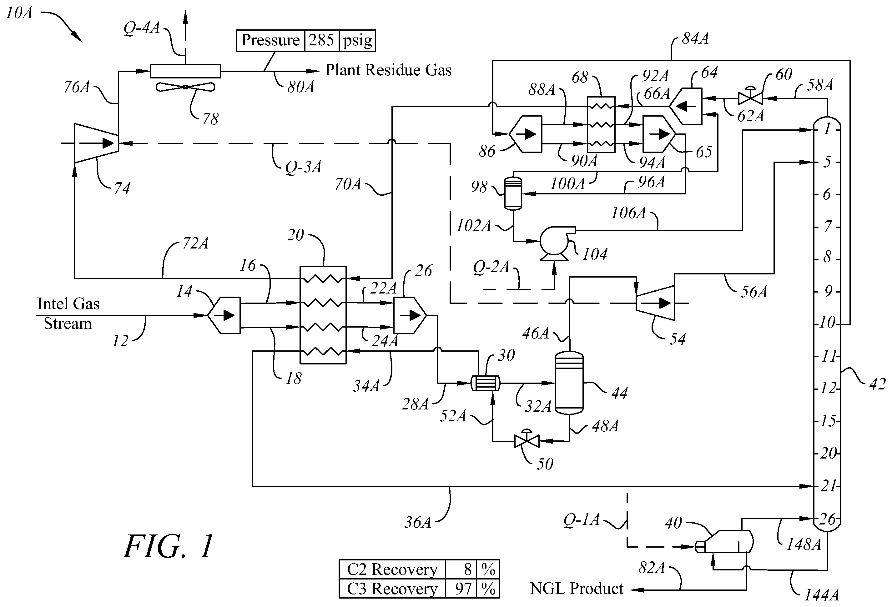
is a process flow diagram illustrating principal processing stages for producing an NGL product stream in ethane rejection mode and without external refrigeration according to a preferred embodiment of the invention;
is a process flow diagram illustrating principal processing stages for producing an NGL product stream in ethane rejection mode and with external refrigeration according to another preferred embodiment of the invention;
is a process flow diagram illustrating principal processing stages for producing an NGL product stream in ethane rejection mode and without external refrigeration according to a preferred alternate embodiment of ; and
is a process flow diagram illustrating principal processing stages for producing an NGL product stream in ethane retention mode according to another preferred embodiment of the invention.
DESCRIPTION OF THE PREFERRED EMBODIMENTS
Example 1—Ethane Rejection without External Refrigeration
Referring to , a preferred embodiment of system 10 A for processing NGL product streams in an ethane rejection mode is shown. System 10 A preferably comprises three heat exchangers 20 , 30 , and 68 , a first separator 44 , a second separator 98 , and a fractionating tower 42 .
Feed stream 12 comprises natural gas that has already been processed according to known methods to remove excessive amounts of H 2 S, CO 2 (as needed), and water. For the particular Example 1 described herein, feed stream 12 has the following basic parameters: (1) Pressure of near 975 PSIG; (2) Inlet temperature of near 120° F.; (3) Inlet gas flow of 100 Million Standard Cubic Feet per Day (MMSCFD); (4) Inlet nitrogen content of 2% by volume; (5) inlet CO 2 content of 1.725% by volume; (6) inlet methane content of 69.51% by volume; (7) inlet ethane content of 14.8% by volume; and (8) inlet propane content of 7.41% by volume. The parameters of other streams described herein are exemplary based on the data for feed stream 12 used in a computer simulation for Example 1. The temperatures, pressures, flow rates, and compositions of other process streams in system 10 A will vary depending on the nature of the feed stream and other operational parameters, as will be understood by those of ordinary skill in the art. Feed stream 12 is preferably directed to the inlet splitter 14 where the inlet gas is strategically split into two streams 16 , 18 before passing through heat exchanger 20 and exiting as streams 22 A, 24 A having been cooled to around 31.4° F. The split between streams 16 and 18 is most preferably 50/50, as in Examples 1-2, but other ratios may also be used. Feed streams 22 A, 24 A are then recombined in mixer 26 to form stream 28 A, which passes through heat exchanger 30 , exiting as stream 32 A having been cooled to around 13° F. Stream 32 A is the feed stream for first separator 44 .
First separator overhead stream 46 A, containing around 77.5% methane, around 12.67% ethane, and around 4.33% propane at 12.86° F. and 962.8 psig, is expanded in expander 54 , exiting as stream 56 A. Stream 56 A, at around −84° F. and 209.3 psig, is fed into fractionating column 42 near a top section of the tower as a fractionating tower feed stream.
First separator bottoms stream 48 A, containing around 40% methane, around 22.6% ethane, and around 18.6% propane at 12.9° F. and 962.8 psig, passes through an expansion valve, exiting as stream 52 A at −38.4° F. and 218.7 psig. Stream 52 A then passes through heat exchanger 30 , exiting as stream 34 A, having been warmed to around 20.6° F. Stream 34 A then passes through the heat exchanger 20 , exiting as stream 36 A warmed to 100° F. In this way, the bottoms stream from separator 44 undergoes two stages of heat exchange with the feed stream—once (as stream 52 ) in heat exchanger 30 (with feed stream 28 A) and again (as stream 34 ) in heat exchanger 20 (with feed streams 16 , 18 , and along with a combined stream 70 A formed by the fractionation column and second separator overhead streams). Stream 36 A is then fed into a lower section of fractionating tower 42 as another fractionating tower feed stream.
A stream 84 A is withdrawn from fractionating tower 42 from a mid-section of the tower. Stream 84 A, containing around 34.1% methane, around 56.96% ethane, and around 6.19% propane at −5.8° F. and 207.4 psig, is split in splitter 86 into streams 88 A and 90 A. Most preferably stream 84 A is split 50/50, but other ratios may also be used. Streams 88 A and 90 A pass through heat exchanger 68 , exiting as streams 92 A, 94 A having been cooled to around −89.5° F. Streams 92 A, 94 A are then recombined in mixer 65 to form stream 96 A, which feeds into second separator 98 .
Second separator bottoms stream 102 A, containing around 21.6% methane, around 68% ethane, and around 7.8% propane at −89.9° F. and 199.9 psig, is preferably pumped with pump 104 , exiting pump 104 as stream 106 A at a pressure of 224.9 psig. Stream 106 A is another feed stream into the top of fractionating tower 42 .
Second separator overhead stream 100 A contains around 79.3% methane, around 17% ethane, and around 0.27% propane at −89.9° F. and 199.9 psig. Fractionating tower overhead stream 58 A contains around 1.98% CO 2 , around 2.3% nitrogen, around 79.8% methane, around 15.6% ethane, and around 0.263% propane at −91.8° F. and 206.32 psig. Stream 58 A is expanded through expansion valve 60 , exiting as stream 62 A at −93.4° F. and 196.32 psig. These two overhead streams 62 A and 100 A are combined in mixer 64 forming stream 66 A, which passes through heat exchanger 68 , exiting as stream 70 A having been warmed to around −11.9° F. Stream 70 A then passes through heat exchanger 20 , exiting as stream 72 A having been warmed to around 110.8° F. Stream 72 A is compressed in compressor 74 (preferably receiving energy Q-3 from expander 54 ), exiting as stream 76 A. Stream 76 A is preferably cooled in heat exchanger 78 to form residue gas stream 80 A, containing around 1.97% CO 2 , around 2.27% nitrogen, around 79.8% methane, around 15.69% ethane, and around 0.26% propane at 120° F. and 285.2 psig.
A liquid stream 144 A is withdrawn from the bottom of fractionating tower 42 , passing through reboiler 40 , with vapor stream 148 A being returned to tower 42 and fractionating tower bottoms stream 82 A exiting as the NGL product stream. Stream 82 A contains negligible nitrogen, 0.05% CO 2 , 0.017% methane, 8.9% ethane, and 55.6% propane. The ethane recovery in NGL product stream 82 A from the feed stream is 8% and the propane recovery in stream 82 A is 97%.
The flow rates, temperatures and pressures of various flow streams referred to in connection with Example 1 of a preferred system and method of the invention in relation to , are based on a computer simulation for system 10 A having the feed stream characteristics discussed above and listed below in Table 1, with a preferred maximum CO 2 feed stream content. System 10 A may be operated with up to 1.725% CO 2 in feed stream 12 without encountering freezing problems typically encountered in prior art systems and while still meeting a 2% maximum CO 2 content in the residue gas specification. This allows system 10 A to be operated without pretreating the feed stream to remove CO 2 or with reduced pretreatment requirements. The flow rates, temperatures and pressures of various flow streams in system 10 A based on a computer simulation of Example 1 using a feed stream having 1.725% CO 2 (and other feed stream content/parameters noted below) are included in Tables 1 and 2 below. These temperatures, pressures, flow rates, and compositions will also vary depending on the nature of other parameters in the feed stream and other operational parameters as will be understood by those of ordinary skill in the art. References to “neg” mean negligible amounts.
TABLE 1
Example 1, System 10A - Rejection Mode without
External Refrigeration
Stream Properties
Property Units 12 16 18 22a 24A
Temperature ° F. 120* 120 120 31.4043* 31.4043*
Pressure psig 975.257* 975.257 975.257 970.257 970.257
Molar Flow lbmol/h 10979.8 5489.91 5489.91 5489.91 5489.91
Mole Fraction Vapor % 100 100 100 85.7573 85.7573
Mole Fraction Light % 0 0 0 14.2427 14.2427
Liquid
Stream Composition
Mole Fraction 12 % 16 % 18 % 22a % 24A %
CO2 1.725* 1.725 1.725 1.725 1.725
N2 1.97538* 1.97538 1.97538 1.97538 1.97538
C1 69.5086* 69.5086 69.5086 69.5086 69.5086
C2 14.8153* 14.8153 14.8153 14.8153 14.8153
C3 7.40766* 7.40766 7.40766 7.40766 7.40766
iC4 0.987688* 0.987688 0.987688 0.987688 0.987688
nC4 2.29638* 2.29638 2.29638 2.29638 2.29638
iC5 0.493844* 0.493844 0.493844 0.493844 0.493844
nC5 0.592613* 0.592613 0.592613 0.592613 0.592613
C6 0.197538* 0.197538 0.197538 0.197538 0.197538
Stream Properties
Property Units 28A 32A 34A 36A 46A
Temperature ° F. 31.4043 13* 20.5789 100* 12.8649
Pressure psig 970.257 965.257 213.72 212.72 962.757
Molar Flow lbmol/h 10979.8 10979.8 2366.83 2366.83 8612.99
Mole Fraction Vapor % 85.7573 78.4427 63.7722 94.8245 100
Mole Fraction Light % 14.2427 21.5573 36.2278 5.17548 0
Liquid
Stream Composition
Mole Fraction 28A % 32A % 34A % 36A % 46A %
CO2 1.725 1.725 1.72385 1.72385 1.72532
N2 1.97538 1.97538 0.534224 0.534224 2.3714
C1 69.5086 69.5086 40.272 40.272 77.5427
C2 14.8153 14.8153 22.6236 22.6236 12.6696
C3 7.40766 7.40766 18.6049 18.6049 4.33069
iC4 0.987688 0.987688 3.17365 3.17365 0.386991
nC4 2.29638 2.29638 7.88993 7.88993 0.759281
iC5 0.493844 0.493844 1.93769 1.93769 0.097078
nC5 0.592613 0.592613 2.37602 2.37602 0.102538
C6 0.197538 0.197538 0.864175 0.864175 0.014347
Stream Properties
Property Units 48A 52A 56A 58A 62A
Temperature ° F. 12.8649 −38.3593 −84.3357 −91.8271 −93.3772
Pressure psig 962.757 218.72* 209.3* 206.32 196.32
Molar Flow lbmol/h 2366.83 2366.83 8612.99 9230.07 9230.07
Mole Fraction Vapor % 0 42.6237 88.6443 100 100
Mole Fraction Light % 100 57.3763 11.3557 0 0
Liquid
Stream Composition
Mole Fraction 48A % 52A % 56A % 58A % 62A %
CO2 1.72385 1.72385 1.72532 1.98165 1.98165
N2 0.534224 0.534224 2.3714 2.29203 2.29203
C1 40.272 40.272 77.5427 79.8173 79.8173
C2 22.6236 22.6236 12.6696 15.6422 15.6422
C3 18.6049 18.6049 4.33069 0.264576 0.264576
iC4 3.17365 3.17365 0.386991 0.001080 0.001080
nC4 7.88993 7.88993 0.759281 0.001217 0.001217
iC5 1.93769 1.93769 0.097078 Neg Neg
nC5 2.37602 2.37602 0.102538 Neg Neg
C6 0.864175 0.864175 0.014347 Neg Neg
Stream Properties
Property Units 66A 70A 72A 76A 80A
Temperature ° F. −93.2767 −11.9376 110.824 181.314 120*
Pressure psig 196.32 191.32 186.32 290.228 285.228
Molar Flow lbmol/h 9563.34 9563.34 9563.34 9563.34 9563.34
Mole Fraction Vapor % 100 100 100 100 100
Mole Fraction Light % 0 0 0 0 0
Liquid
Stream Composition
Mole Fraction 66A % 70A % 72A % 76A % 80A %
CO2 1.97326 1.97326 1.97326 1.97326 1.97326
N2 2.26796 2.26796 2.26796 2.26796 2.26796
C1 79.8015 79.8015 79.8015 79.8015 79.8015
C2 15.69 15.69 15.69 15.69 15.69
C3 0.265 0.265 0.265 0.265 0.265
iC4 0.001082 0.001082 0.001082 0.001082 0.001082
nC4 0.001220 0.001220 0.001220 0.001220 0.001220
iC5 Neg Neg Neg Neg Neg
nC5 Neg Neg Neg Neg Neg
C6 Neg Neg Neg Neg Neg
Stream Properties
Property Units 82A 84A 88A 90A 92A
Temperature ° F. 122.929 −5.78509 −5.78509 −5.78509 −89.5251*
Pressure psig 210.82 207.4 207.4 207.4 202.4
Molar Flow lbmol/h 1416.49 1537.18 768.588 768.588 768.588
Mole Fraction Vapor % 0 100 100 100 21.4649
Mole Fraction Light % 100 0 0 0 78.5351
Liquid
Stream Composition
Mole Fraction 82A % 84A % 88A % 90A % 92A %
CO2 0.048869 2.01951 2.01951 2.01951 2.01951
N2 Neg 0.415043 0.415043 0.415043 0.415043
C1 0.016567 34.0876 34.0876 34.0876 34.0876
C2 8.90998 56.9581 56.9581 56.9581 56.9581
C3 55.6312 6.18507 6.18507 6.18507 6.18507
iC4 7.64871 0.131199 0.131199 0.131199 0.131199
nC4 17.792 0.188893 0.188893 0.188893 0.188893
iC5 3.82794 0.008024 0.008024 0.008024 0.008024
nC5 4.59357 0.006397 0.006397 0.006397 0.006397
C6 1.5312 0.000167 0.000167 0.000167 0.000167
Stream Properties
Property Units 94A 96A 100A 102A 106A
Temperature ° F. −89.5251* −89.5251 −89.9471 −89.9471 −89.6931
Pressure psig 202.4 202.4 199.9 199.9 224.9
Molar Flow lbmol/h 768.588 1537.18 333.27 1203.91 1203.91
Mole Fraction Vapor % 21.4649 21.4649 100 0 0
Mole Fraction Light % 78.5351 78.5351 0 100 100
Liquid
Stream Composition
Mole Fraction 94A % 96A % 100A % 102A % 106A %
CO2 2.01951 2.01951 1.74097 2.09661 2.09661
N2 0.415043 0.415043 1.6013 0.086659 0.086659
C1 34.0876 34.0876 79.3641 21.554 21.554
C2 56.9581 56.9581 17.0144 68.0155 68.0155
C3 6.18507 6.18507 0.276723 7.82065 7.82065
iC4 0.131199 0.131199 0.001160 0.167197 0.167197
nC4 0.188893 0.188893 0.001311 0.24082 0.24082
iC5 0.008024 0.008024 Neg 0.010243 0.010243
nC5 0.006397 0.006397 Neg 0.008167 0.008167
C6 0.000167 0.000167 Neg 0.000214 0.000214
Stream Properties
Property Units 144A 148A
Temperature ° F. 107.742 122.929
Pressure psig 210.82 210.82
Molar Flow lbmol/h 1993.57 577.081
Mole Fraction Vapor % 0 100
Mole Fraction Light % 100 0
Liquid
Stream Composition
Mole Fraction 144A % 148A %
CO2 0.112279 0.267921
N2 Neg Neg
C1 0.059564 0.165105
C2 13.3865 24.3744
C3 57.2242 61.1345
iC4 6.70408 4.38544
nC4 14.8899 7.76634
iC5 2.97541 0.882816
nC5 3.52681 0.908379
C6 1.12128 0.115109
TABLE 2
Example 1, System 10A Energy Streams - Maximum CO 2 Content
Energy Energy Rate
Stream (MBTU/h) Power (hp) From Block To Block
Q-1A 4077.77 — Reboiler 40
Q-2A 6.798 — Pump 104
Q-3A 6218.61 2444 Expander 54 Compressor 74
Q-4A 5950.59 Heat —
Exchanger/
Cooler 78
It will be appreciated by those of ordinary skill in the art that the values in the Tables are based on the particular parameters and composition of the feed stream in the above examples. The values will differ depending on the parameters and composition of the feed stream 12 and operational parameters for system 10 A as will be understood by those of ordinary skill in the art.
Example 2—Ethane Rejection with External Refrigeration
Referring to , system 10 B for processing NGL product streams in an ethane rejection mode according to another preferred embodiment is shown. System 10 B preferably comprises heat exchangers 20 , 30 , and 68 , a first separator 44 , a second separator 98 , and a fractionating tower 42 , just as in system 10 A. The equipment and stream flows from one piece of equipment to another in system 10 B are the same as with system 10 A except that system 10 B includes an additional heat exchanger 110 that provides external refrigeration to stream 84 B (a side stream withdrawn from a mid-point in tower 42 ) prior to passing through heat exchanger 68 . In system 10 B, stream 84 B is withdrawn from a mid-point in fractionation tower 42 and contains 34.5% methane, 59.1% ethane, and 3.7% propane at −0.17° F. and 275.97 psig, based on the parameters and content of feed stream 12 for Example 2, as indicated in Tables 3-4 below. Stream 84 B passes through heat exchanger/external refrigeration 110 , exiting as stream 84 B-R having been cooled to −30° F. Stream 84 B-R is then split into streams 88 B, 90 B in splitter 86 before passing through heat exchanger 68 , as in system 10 A. Most preferably stream 84 B-R is split 50/50, but other ratios may also be used.
The temperatures, pressures, and compositional makeup of the streams and operating parameters of the equipment in system 10 B (other than the initial feed streams 12 , 16 , 18 ) will differ from system 10 A because of the addition of the external refrigeration as will be understood by those of ordinary skill in the art. For example, tower 42 in system 10 B will operate at higher pressures than with system 10 A and the bottoms stream from separator 98 that feeds into the top of tower 42 in system 10 B (stream 106 B) will have a higher methane content and lower ethane content than the same stream ( 106 A) in system 10 A. There are additional operating and equipment costs associated with system 10 B compared with system 10 A, but the ethane recovery in the NGL product stream is better (lower) than in system 10 A and the propane recovery is slightly higher. In addition, the residue gas exits 10 B at a higher pressure allowing for less compression to be utilized to compress the treated gas for introduction into typical natural gas transmission pipelines. The ethane recovery in NGL product stream 40 B from the feed stream is 5% and the propane recovery in stream 40 B is 98% in Example 2. When it is desirable to reject ethane, typical NGL specifications limit ethane retention from the feed to between 5-15% to meet other specifications. Systems 10 A and 10 B both meet these requirements, but system 10 B retains less ethane (5% in Example 2) than system 10 A (8% in Example 1).
The flow rates, temperatures and pressures of various flow streams referred to in connection with Example 2 of a preferred system and method of the invention in relation to , are based on a computer simulation for system 10 B having the feed stream characteristics discussed above and listed below in Table 3, with a preferred maximum CO 2 feed stream content. System 10 B may be operated with up to 1.725% CO 2 in feed stream 12 without encountering freezing problems typically encountered in prior art systems and while still meeting a 2% maximum CO 2 content in the residue gas specification. This allows system 10 B to be operated without pretreating the feed stream to remove CO 2 or with reduced pretreatment requirements. The flow rates, temperatures and pressures of various flow streams in system 10 B based on a computer simulation of Example 2 using a feed stream having 1.725% CO 2 (and other feed stream content/parameters noted below) are included in Tables 3 and 4 below. These temperatures, pressures, flow rates, and compositions will also vary depending on the nature of other parameters in the feed stream and other operational parameters as will be understood by those of ordinary skill in the art.
TABLE 3
Example 2, System 10B - Rejection Mode with External
Refrig.
Stream Properties
Property Units 12 16 18 22B 24B
Temperature ° F. 120* 120 120 21.4342* 21.4342*
Pressure psig 975.257* 975.257 975.257 970.257 970.257
Molar Flow lbmol/h 10979.8 5489.91 5489.91 5489.91 5489.91
Mole Fraction Vapor % 100 100 100 81.9067 81.9067
Mole Fraction Light % 0 0 0 18.0933 18.0933
Liquid
Stream Composition
Mole Fraction 12 % 16 % 18 % 22B % 24B %
CO2 1.725* 1.725 1.725 1.725 1.725
N2 1.97538* 1.97538 1.97538 1.97538 1.97538
C1 69.5086* 69.5086 69.5086 69.5086 69.5086
C2 14.8153* 14.8153 14.8153 14.8153 14.8153
C3 7.40766* 7.40766 7.40766 7.40766 7.40766
iC4 0.987688* 0.987688 0.987688 0.987688 0.987688
nC4 2.29638* 2.29638 2.29638 2.29638 2.29638
iC5 0.493844* 0.493844 0.493844 0.493844 0.493844
nC5 0.592613* 0.592613 0.592613 0.592613 0.592613
C6 0.197538* 0.197538 0.197538 0.197538 0.197538
Stream Properties
Property Units 28B 32B 34B 36B 46B
Temperature ° F. 21.4342 2.5* 11.8659 85* 2.36321
Pressure psig 970.257 965.257 282.289 281.289 962.757
Molar Flow lbmol/h 10979.8 10979.8 2908.72 2908.72 8071.11
Mole Fraction Vapor % 81.9067 73.4966 59.5283 87.9487 100
Mole Fraction Light % 18.0933 26.5034 40.4717 12.0513 0
Liquid
Stream Composition
Mole Fraction 28B % 32B % 34B % 36B % 46B %
CO2 1.725 1.725 1.80859 1.80859 1.69487
N2 1.97538 1.97538 0.58266 0.58266 2.47729
C1 69.5086 69.5086 43.1184 43.1184 79.0192
C2 14.8153 14.8153 22.7741 22.7741 11.9471
C3 7.40766 7.40766 17.5076 17.5076 3.7678
iC4 0.987688 0.987688 2.8493 2.8493 0.316788
nC4 2.29638 2.29638 6.96576 6.96576 0.613593
iC5 0.493844 0.493844 1.65789 1.65789 0.074339
nC5 0.592613 0.592613 2.0192 2.0192 0.078490
C6 0.197538 0.197538 0.71647 0.71647 0.010521
Stream Properties
Property Units 48B 52B 56B 58B 62B
Temperature ° F. 2.36321 −42.5725 −80.119 −82.5718 −83.9354
Pressure psig 962.757 287.289* 277.869* 274.889 264.889
Molar Flow lbmol/h 2908.72 2908.72 8071.11 9259.99 9259.99
Mole Fraction Vapor % 0 39.8756 88.8805 100 99.9658
Mole Fraction Light % 100 60.1244 11.1195 0 0.0342231
Liquid
Stream Composition
Mole Fraction 48B % 52B % 56B % 58B % 62B %
CO2 1.80859 1.80859 1.69487 1.98114 1.98114
N2 0.58266 0.58266 2.47729 2.27468 2.27468
C1 43.1184 43.1184 79.0192 79.5349 79.5349
C2 22.7741 22.7741 11.9471 16.028 16.028
C3 17.5076 17.5076 3.7678 0.179253 0.179253
iC4 2.8493 2.8493 0.316788 0.000898 0.000898
nC4 6.96576 6.96576 0.613593 0.001099 0.001099
iC5 1.65789 1.65789 0.074339 Neg Neg
nC5 2.0192 2.0192 0.078490 Neg Neg
C6 0.71647 0.71647 0.010521 Neg Neg
Stream Properties
Property Units 66B 70B 72B 76B 80B
Temperature ° F. −83.8091 −34.2366 111.129 164.302 120*
Pressure psig 264.889 259.889 254.889 354.998 349.998
Molar Flow lbmol/h 9599.19 9599.19 9599.19 9599.19 9599.19
Mole Fraction Vapor % 99.9664 100 100 100 100
Mole Fraction Light % 0.0335718 0 0 0 0
Liquid
Stream Composition
Mole Fraction 66B % 70B % 72B % 76B % 80B %
CO2 1.972 1.972 1.972 1.972 1.972
N2 2.25949 2.25949 2.25949 2.25949 2.25949
C1 79.5055 79.5055 79.5055 79.5055 79.5055
C2 16.0813 16.0813 16.0813 16.0813 16.0813
C3 0.179689 0.179689 0.179689 0.179689 0.179689
iC4 0.000901 0.000901 0.000901 0.000901 0.000901
nC4 0.001102 0.001102 0.001102 0.001102 0.001102
iC5 Neg Neg Neg Neg Neg
nC5 Neg Neg Neg Neg Neg
C6 Neg Neg Neg Neg Neg
Stream Properties
Property Units 82B 84B 84B-R 88B 90B
Temperature ° F. 155.657 −0.16483 −30* −30 −30
Pressure psig 279.389 275.969 273.469 273.469 273.469
Molar Flow lbmol/h 1380.65 2031.27 2031.27 1015.63 1015.63
Mole Fraction Vapor % 0 100 57.9531 57.9531 57.9531
Mole Fraction Light % 100 0 42.0469 42.0469 42.0469
Liquid
Stream Composition
Mole Fraction 82B % 84B % 84B-R % 88B % 90B %
CO2 0.007705 2.08811 2.08811 2.08811 2.08811
N2 Neg 0.421425 0.421425 0.421425 0.421425
C1 0.003187 34.4929 34.4929 34.4929 34.4929
C2 6.01175 59.0521 59.0521 59.0521 59.0521
C3 57.663 3.7223 3.7223 3.7223 3.7223
iC4 7.84852 0.084769 0.084769 0.084769 0.084769
nC4 18.2547 0.128476 0.128476 0.128476 0.128476
iC5 3.92731 0.005446 0.005446 0.005446 0.005446
nC5 4.71282 0.004394 0.004394 0.004394 0.004394
C6 1.57095 0.000123 0.000123 0.000123 0.000123
Stream Properties
Property Units 92B 94B 96B 100b 102B
Temperature ° F. −79.9266* −79.9266* −79.9266 −80.2819 −80.2819
Pressure psig 268.469 268.469 268.469 265.969 265.969
Molar Flow lbmol/h 1015.63 1015.63 2031.27 339.196 1692.07
Mole Fraction Vapor % 16.4886 16.4886 16.4886 100 0
Mole Fraction Light % 83.5114 83.5114 83.5114 0 100
Liquid
Stream Composition
Mole Fraction 92B % 94B % 96B % 100b % 102B %
CO2 2.08811 2.08811 2.08811 1.7225 2.1614
N2 0.421425 0.421425 0.421425 1.8448 0.136093
C1 34.4929 34.4929 34.4929 78.7018 25.6307
C2 59.0521 59.0521 59.0521 17.5372 67.3743
C3 3.7223 3.7223 3.7223 0.191595 4.43007
iC4 0.084769 0.084769 0.084769 0.000971 0.101568
nC4 0.128476 0.128476 0.128476 0.001189 0.153992
iC5 0.005446 0.005446 0.005446 Neg 0.006536
nC5 0.004394 0.004394 0.004394 Neg 0.005273
C6 0.000123 0.000123 0.000123 Neg 0.000148
Stream Properties
Property Units 106B 144B 148B
Temperature ° F. −79.9982 137.594 155.657
Pressure psig 290.969 279.389 279.389
Molar Flow lbmol/h 1692.07 2748.73 1368.08
Mole Fraction Vapor % 0 0 100
Mole Fraction Light % 100 100 0
Liquid
Stream Composition
Mole Fraction 106B % 144B % 148B %
CO2 2.1614 0.0212266 0.034872
N2 0.136093 Neg Neg
C1 25.6307 0.013306 0.023517
C2 67.3743 10.4733 14.9759
C3 4.43007 62.343 67.066
iC4 0.101568 6.58462 5.30911
nC4 0.153992 14.0647 9.83618
iC5 0.006536 2.59052 1.24145
nC5 0.005273 3.02201 1.31567
C6 0.000148 0.887282 0.197333
TABLE 4
Example 2, System 10B Energy Streams
Energy Energy Rate Power
Stream (MBtu/hr) (hp) From To
Q-1B 8450.5 — Reboiler 40
Q-2B 9.605 — Pump 104
Q-3B 4613.45 1360.1 Expander 54 Compressor 74
Q-4B 4340.39 Heat —
Exchanger/Cooler
78
Q-5B 4613.9 Heat —
Exchanger/External
Refrigeration 110
It will be appreciated by those of ordinary skill in the art that the values in the Tables are based on the particular parameters and composition of the feed stream in the above examples. The values will differ depending on the parameters and composition of the feed stream 12 and operational parameters for system 10 B as will be understood by those of ordinary skill in the art.
Systems 10 A and 10 B are similar to in U.S. Pat. No. 5,799,507. One important difference between systems 10 A and 10 B and the system depicted in of the '507 patent is that the heat exchange systems are different, including the use of external refrigeration in system 10 B, which is not used in of the '507 patent. In systems 10 A and 10 B, feed stream 12 is split with each part of the feed stream (streams 16 and 18 ) passing through heat exchanger 20 (upstream of heat exchanger 30 ) with the mixed fractionation tower overhead stream and second separator overhead stream 70 A/ 70 B (downstream of heat exchanger 68 ) and first separator bottoms stream 34 A/ 34 B (downstream of heat exchanger 30 ). In the '507 patent, the feed stream is not split and the first bottoms stream is not warmed prior to heat exchange with the feed stream and mixed fractionation tower overhead stream and second separator bottoms stream. By passing the first separator bottoms stream through heat exchangers 30 and 20 , it is possible to warm that stream sufficiently that it feeds into fractionation tower 42 (as stream 36 A/ 36 B) at a higher temperature (up to 110° F., depending on the inlet gas composition and operating conditions, although that stream may also feed into fractionation tower 42 at temperatures in the range of 25° F. to 110° F.) than the 65° F. of stream 33 b in the '507 patent. This makes it possible to operate fractionation tower 42 with minimal external heat input which in turn allows for a greater efficiency overall. It also allows the feed stream into first separator 44 (streams 32 A/ 32 B) to be warmer (in the range of −25° F. to +25° F. for the non-refrigerated system 10 A and a range of −50° F. to 0° F. for the refrigerated system 10 B) than the first separator feed stream 31 a (at −73° F.) in the '507 patent. For systems 10 A and 10 B, the higher separator 44 temperature allows for greater amount of energy or “refrigeration” to be delivered to the system from the expander 54 . Since one of the benefits of the preferred embodiments of the invention is to be able to operate system 10 A without refrigeration, the higher temperature and thus the greater refrigeration generated is beneficial. Additionally, in systems 10 A and 10 B, the side stream 84 A/ 84 B withdrawn from fractionation tower 42 passes through heat exchanger 68 for heat exchange with the mixed fractionation tower overhead stream and second separator bottoms stream 66 A/ 66 B. In the '507 patent, the side stream 36 passes through heat exchanger 20 with only the fractionation tower overhead stream. The heat exchange system in systems 10 A and 10 B allow the feed stream into second separator 98 (streams 96 A/ 96 B) to be at a warmer temperature (in the range of in a range of −70° F. to −95° F. for the non-refrigerated system 10 A and −71° F. to −125° F. for system 10 B with external refrigeration), than the second separator feed stream 36 a (at −116° F.) in the '507 patent. One benefit of the higher temperature is to allow for more of the methane and ethane to be eliminated from the fractionator 42 as vapor (in overhead stream 58 A/ 58 B) and allow for a desired compositional change for the top feed stream 106 B into the fractionation tower 42 .
In addition to operational temperature differences based on the different heat exchange systems, operating pressures in systems 10 A and 10 B differ from those in of the '507 patent. The first separator 44 in systems 10 A and 10 B operates at a pressure between 800 and 1100 psig, which is higher than the first separator 11 in the '507 patent (570 psia). In system 10 A, the second separator 98 operates at a pressure between 150 and 300 psig. This is lower than the second separator 15 in the '507 patent, which operates at a pressure of 353 psia, similar to the range of 250 to 400 psig for system 10 B, with external refrigeration. In system 10 A, the fractionation tower operates at a pressure between 150 and 300 psig. This is also lower than the fractionation tower 17 in the '507 patent, which operates at a pressure of 355 psia, similar to the range of 300 and 400 psig for the fractionation tower in system 10 B.
The propane recovery in the NGL product stream for the system in in the '507 patent is 94%, with very low ethane in the NGL product stream. With the process changes in systems 10 A and 10 B noted above and in , system 10 A is able to achieve a 97% propane recovery with only 8% ethane recovery in the NGL product stream and system 10 B is able to achieve a 98% propane recovery with only 5% ethane recovery in the NGL product stream using essentially the same equipment.
Example 3—Alternate Ethane Rejection without External Refrigeration
Referring to , an alternate preferred embodiment of system 10 A is shown. System 10 A- 2 is a preferred alternate embodiment for processing NGL product streams in an ethane rejection mode that is particularly useful when the incoming feed stream 12 contains higher contents of condensable hydrocarbon components. System 10 A- 2 is preferably has the same equipment and process flows as system 10 A, but an additional side stream 54 Alt is withdrawn from fractionation tower 42 , warmed in heat exchanger 20 , and fed back into tower 42 as stream 55 Alt.
Feed stream 12 comprises natural gas that has already been processed according to known methods to remove excessive amounts of H 2 S, CO 2 , and water, as needed. For the particular Example 3 described herein, feed stream 12 has the following basic parameters: (1) Pressure of near 975 PSIG; (2) Inlet temperature of near 120° F.; (3) Inlet gas flow of 100 Million Standard Cubic Feet per Day (MMSCFD); (4) Inlet nitrogen content of 2% by volume; (5) inlet CO 2 content of 0.5% by volume; (6) inlet methane content of 70.375% by volume; (7) inlet ethane content of 15% by volume; and (8) inlet propane content of 7.5 by volume. The parameters of other streams described herein are exemplary based on the data for feed stream 12 used in a computer simulation for Example 3. The temperatures, pressures, flow rates, and compositions of other process streams in system 10 A- 2 will vary depending on the nature of the feed stream and other operational parameters, as will be understood by those of ordinary skill in the art. Feed stream 12 is preferably directed to the inlet splitter 14 where the inlet gas is strategically split into two streams 16 , 18 before passing through heat exchanger 20 and exiting as streams 22 Alt, 24 Alt having been cooled to around 31.3° F. The split between streams 16 and 18 is most preferably 50/50, as in Examples 1-2, but other ratios may also be used. Feed streams 22 Alt, 24 Alt are then recombined in mixer 26 to form stream 28 Alt, which passes through heat exchanger 30 , exiting as stream 32 Alt having been cooled to around 12.5° F. Stream 32 Alt is the feed stream for first separator 44 .
First separator overhead stream 46 Alt, containing around 78.6% methane, around 12.78% ethane, and around 4.33% propane at 12.36° F. and 962.8 psig, is expanded in expander 54 , exiting as stream 56 Alt. Stream 56 Alt, at around −84° F. and 209.3 psig, is fed into fractionating column 42 near a top section of the tower as a fractionating tower feed stream.
First separator bottoms stream 48 Alt, containing around 40% methane, around 22.96% ethane, and around 18.84% propane at 12.3° F. and 962.8 psig, passes through an expansion valve, exiting as stream 52 Alt at −38.1° F. and 218.7 psig. Stream 52 Alt then passes through heat exchanger 30 , exiting as stream 34 Alt, having been warmed to around 21.3° F. Stream 34 Alt then passes through the heat exchanger 20 , exiting as stream 36 Alt warmed to 94.9° F. In this way, the bottoms stream from separator 44 undergoes two stages of heat exchange with the feed stream—once (as stream 52 Alt) in heat exchanger 30 (with feed stream 28 Alt) and again (as stream 34 Alt) in heat exchanger 20 (with feed streams 16 , 18 , and along with a combined stream 70 Alt formed by the fractionation column and second separator overhead streams). Stream 36 Alt is then fed into a lower section of fractionating tower 42 as another fractionating tower feed stream.
A stream 84 Alt is withdrawn from fractionating tower 42 from a mid-section of the tower. Stream 84 Alt, containing around 34.8% methane, around 58.2% ethane, and around 5.57% propane at −7.3° F. and 207.4 psig, is split in splitter 86 into streams 88 Alt and 90 Alt. Most preferably stream 84 Alt is split 50/50, but other ratios may also be used. Streams 88 Alt and 90 Alt pass through heat exchanger 68 , exiting as streams 92 Alt, 94 Alt having been cooled to around −89.5° F. Streams 92 Alt, 94 Alt are then recombined in mixer 65 to form stream 96 Alt, which feeds into second separator 98 .
Second separator bottoms stream 102 Alt, containing around 21.75% methane, around 70% ethane, and around 7.1% propane at −89.9° F. and 199.9 psig, is preferably pumped with pump 104 , exiting pump 104 as stream 106 Alt at a pressure of 224.9 psig. Stream 106 Alt is another feed stream into the top of fractionating tower 42 .
Second separator overhead stream 100 Alt contains around 80.1% methane, around 17.5% ethane, and around 0.25% propane at −89.9° F. and 199.9 psig. Fractionating tower overhead stream 58 Alt contains around 0.58% CO 2 , around 2.3% nitrogen, around 81% methane, around 15.8% ethane, and around 0.234% propane at −92.6° F. and 206.32 psig. Stream 58 Alt is expanded through expansion valve 60 , exiting as stream 62 Alt at −94.2° F. and 196.32 psig. These two overhead streams 62 Alt and 100 Alt are combined in mixer 64 forming stream 66 Alt, which passes through heat exchanger 68 , exiting as stream 70 Alt having been warmed to around −11.9° F. Stream 70 Alt then passes through heat exchanger 20 , exiting as stream 72 Alt having been warmed to around 115.5° F. Stream 72 Alt is compressed in compressor 74 (preferably receiving energy Q-3A from expander 54 ), exiting as stream 76 Alt. Stream 76 Alt is preferably cooled in heat exchanger 78 to form residue gas stream 80 Alt, containing around 0.57% CO 2 , around 2.3% nitrogen, around 81% methane, around 15.89% ethane, and around 0.235% propane at 120° F. and 284.2 psig.
A stream 54 Alt is withdrawn from fractionating tower 42 from a mid-section of the tower. Stream 54 Alt, containing around 5.2% methane, around 63.44% ethane, and around 25.22% propane at −7.4° F. and 207.4 psig, passes through heat exchanger 20 , exiting as stream 55 Alt having been warmed to around 2.8° F. Stream 55 Alt is then returned to tower 42 at a tray location (such as 15 ) that is lower than the location (such as tray 10 ) where stream 54 Alt was withdrawn.
A liquid stream 144 Alt is withdrawn from the bottom of fractionating tower 42 , passing through reboiler 40 , with vapor stream 148 Alt being returned to tower 42 and fractionating tower bottoms stream 82 Alt exiting as the NGL product stream. Stream 82 Alt contains negligible nitrogen, 0.01% CO 2 , 0.012% methane, 9.1% ethane, and 55.6% propane. The ethane recovery in NGL product stream 82 Alt from the feed stream is 8% and the propane recovery in stream 82 Alt is 97%.
The flow rates, temperatures and pressures of various flow streams referred to in connection with Example 3 of a preferred system and method of the invention in relation to , are based on a computer simulation for system 10 A- 2 having the feed stream characteristics discussed above and listed below in Table 5. The flow rates, temperatures and pressures of various flow streams in system 10 A- 2 based on a computer simulation of Example 3 using a feed stream having the feed stream content/parameters noted above are included in Tables 5 and 6 below. These temperatures, pressures, flow rates, and compositions will also vary depending on the nature of other parameters in the feed stream and other operational parameters as will be understood by those of ordinary skill in the art.
TABLE 5
Example 3, System 10A-2 - Alternate Rejection Mode
without External Refrigeration
Stream Properties
Property Units 12 16 18 22Alt 24Alt
Temperature ° F. 120* 120 120 31.3182* 31.3182*
Pressure psig 975.257* 975.257 975.257 970.257 970.257
Molar Flow lbmol/h 10979.8 5489.91 5489.91 5489.91 5489.91
Mole Fraction Vapor % 100 100 100 85.5855 85.5855
Mole Fraction Light % 0 0 0 14.4145 14.4145
Liquid
Stream Composition
Mole Fraction 12 % 16 % 18 % 22Alt % 24Alt %
CO2 0.5* 0.5 0.5 0.5 0.5
N2 2* 2 2 2 2
C1 70.375* 70.375 70.375 70.375 70.375
C2 15* 15 15 15 15
C3 7.5* 7.5 7.5 7.5 7.5
iC4 1* 1 1 1 1
nC4 2.325* 2.325 2.325 2.325 2.325
iC5 0.5* 0.5 0.5 0.5 0.5
nC5 0.6* 0.6 0.6 0.6 0.6
C6 0.2* 0.2 0.2 0.2 0.2
Stream Properties
Property Units 28Alt 32Alt 34Alt 36Alt 46Alt
Temperature ° F. 31.3182 12.5* 21.3102 94.9041* 12.366
Pressure psig 970.257 965.257 213.72 212.72 962.757
Molar Flow lbmol/h 10979.8 10979.8 2391.52 2391.52 8588.31
Mole Fraction Vapor % 85.5855 78.217 63.5045 92.7673 100
Mole Fraction Light % 14.4145 21.783 36.4955 7.2327 0
Liquid
Stream Composition
Mole Fraction 28Alt % 32Alt % 34Alt % 36Alt % 46Alt %
CO2 0.5 0.5 0.498317 0.498317 0.500469
N2 2 2 0.537953 0.537953 2.40712
C1 70.375 70.375 40.7689 40.7689 78.6192
C2 15 15 22.9642 22.9642 12.7823
C3 7.5 7.5 18.8482 18.8482 4.33995
iC4 1 1 3.20697 3.20697 0.385442
nC4 2.325 2.325 7.96563 7.96563 0.754301
iC5 0.5 0.5 1.95084 1.95084 0.095995
nC5 0.6 0.6 2.3912 2.3912 0.10122
C6 0.2 0.2 0.867769 0.867769 0.014052
Stream Properties
Property Units 48Alt 52Alt 54Alt 55Alt
Temperature ° F. 12.366 −38.1371 −7.3886 2.79454
Pressure psig 962.757 218.72* 207.4 207.4
Molar Flow lbmol/h 2391.52 2391.52 198.764 198.764
Mole Fraction Vapor % 0 42.3976 0 6.5708
Mole Fraction Light % 100 57.6024 100 93.4292
Liquid
Stream Composition
Mole Fraction 48Alt % 52Alt % 54Alt % 55Alt %
CO2 0.498317 0.498317 0.242364 0.242364
N2 0.537953 0.537953 0.017909 0.017909
C1 40.7689 40.7689 5.28582 5.28582
C2 22.9642 22.9642 63.44 63.44
C3 18.8482 18.8482 25.2271 25.2271
iC4 3.20697 3.20697 1.70201 1.70201
nC4 7.96563 7.96563 3.23374 3.23374
iC5 1.95084 1.95084 0.388744 0.388744
nC5 2.3912 2.3912 0.406903 0.406903
C6 0.867769 0.867769 0.055441 0.055441
Stream Properties
Property Units 56Alt 58Alt 62Alt 66Alt 70Alt
Temperature ° F. −84.7827 −92.6801 −94.2226 −94.0838 −11.9284
Pressure psig 209.3* 206.32 196.32 196.32 191.32
Molar Flow lbmol/h 8588.31 9188.66 9188.66 9539.55 9539.55
Mole Fraction Vapor % 88.7593 100 100 100 100
Mole Fraction Light % 11.2407 0 0 0 0
Liquid
Stream Composition
Mole Fraction 56Alt % 58Alt % 62Alt % 66Alt % 70Alt %
CO2 0.500469 0.575758 0.575758 0.573715 0.573715
N2 2.40712 2.32929 2.32929 2.30196 2.30196
C1 78.6192 81.0318 81.0318 80.9981 80.9981
C2 12.7823 15.8264 15.8264 15.8887 15.8887
C3 4.33995 0.234707 0.234707 0.235361 0.235361
iC4 0.385442 0.000987 0.000987 0.000991 0.000991
nC4 0.754301 0.001128 0.001128 0.001133 0.001133
iC5 0.095995 Neg Neg Neg Neg
nC5 0.10122 Neg Neg Neg Neg
C6 0.0140518 Neg Neg Neg Neg
Stream Properties
Property Units 72Alt 76Alt 80Alt 82Alt 84Alt
Temperature ° F. 115.573 185.762 120* 122.632 −7.3886
Pressure psig 186.32 289.236 284.236 210.82 207.4
Molar Flow lbmol/h 9539.55 9539.55 9539.55 1440.26 1568.3
Mole Fraction Vapor % 100 100 100 0 100
Mole Fraction Light % 0 0 0 100 0
Liquid
Stream Composition
Mole Fraction 72Alt % 76Alt % 80Alt % 82Alt % 84Alt %
CO2 0.573715 0.573715 0.573715 0.0117399 0.59017
N2 2.30196 2.30196 2.30196 Neg 0.421289
C1 80.9981 80.9981 80.9981 0.012901 34.8151
C2 15.8887 15.8887 15.8887 9.11556 58.2885
C3 0.235361 0.235361 0.235361 55.6153 5.57009
iC4 0.000991 0.000991 0.000991 7.61693 0.122805
nC4 0.001133 0.001133 0.001133 17.7171 0.178391
iC5 Neg Neg Neg 3.81169 0.00753
nC5 Neg Neg Neg 4.57407 0.005969
C6 Neg Neg Neg 1.5247 0.000154
Stream Properties
Property Units 88Alt 90Alt 92Alt 94Alt 96Alt
Temperature ° F. −7.3886 −7.3886 −89.4918* −89.4918* −89.4918
Pressure psig 207.4 207.4 202.4 202.4 202.4
Molar Flow lbmol/h 784.149 784.149 784.149 784.149 1568.3
Mole Fraction Vapor % 100 100 22.1606 22.1606 22.1606
Mole Fraction Light % 0 0 77.8394 77.8394 77.8394
Liquid
Stream Composition
Mole Fraction 88Alt % 90Alt % 92Alt % 94Alt % 96Alt %
CO2 0.59017 0.59017 0.59017 0.59017 0.59017
N2 0.421289 0.421289 0.421289 0.421289 0.421289
C1 34.8151 34.8151 34.8151 34.8151 34.8151
C2 58.2885 58.2885 58.2885 58.2885 58.2885
C3 5.57009 5.57009 5.57009 5.57009 5.57009
iC4 0.122805 0.122805 0.122805 0.122805 0.122805
nC4 0.178391 0.178391 0.178391 0.178391 0.178391
iC5 0.00753 0.00753 0.00753 0.00753 0.00753
nC5 0.005969 0.005969 0.005969 0.005969 0.005969
C6 0.000154 0.000154 0.000154 0.000154 0.000154
Stream Properties
Property Units 100Alt 102Alt 106Alt 144Alt
Temperature ° F. −89.9119 −89.9119 −89.6562 107.16
Pressure psig 199.9 199.9 224.9 210.82
Molar Flow lbmol/h 350.897 1217.4 1217.4 2058.62
Mole Fraction Vapor % 100 0 0 0
Mole Fraction Light % 0 100 100 100
Liquid
Stream Composition
Mole Fraction 100Alt % 102Alt % 106Alt % 144Alt %
CO2 0.520234 0.610328 0.610328 0.0275215
N2 1.58632 0.085485 0.085485 1.7592E−06
C1 80.1178 21.7573 21.7573 0.0476131
C2 17.5208 70.0392 70.0392 13.8544
C3 0.252481 7.10281 7.10281 57.2213
iC4 0.00109502 0.157887 0.157887 6.63664
nC4 0.00125556 0.229448 0.229448 14.7109
iC5 Neg 0.009697 0.009697 2.92981
nC5 Neg 0.007688 0.007688 3.47077
C6 Neg 0.000199 0.000199 1.10098
Stream Properties
Property Units 148Alt
Temperature ° F. 122.632
Pressure psig 210.82
Molar Flow lbmol/h 618.366
Mole Fraction Vapor % 100
Mole Fraction Light % 0
Liquid
Stream Composition
Mole Fraction 148Alt %
CO2 0.0642789
N2 Neg
C1 0.128462
C2 24.8919
C3 60.962
iC4 4.3534
nC4 7.70903
iC5 0.875804
nC5 0.901052
C6 0.114059
TABLE 6
Example 3, System 10A-2 Alternate Energy Streams
Energy Energy Rate Power
Stream (MBtu/hr) (hp) From To
Q-1A 4346.01 — Reboiler 40
Q-2A 6.90435 — Pump 104
Q-3A 6209.4 2440.39 Expander 54 Compressor 74
Q-4A 6374.95 Heat —
Exchanger/Cooler
78
It will be appreciated by those of ordinary skill in the art that the values in the Tables are based on the particular parameters and composition of the feed stream in the above Example 3. The values will differ depending on the parameters and composition of the feed stream 12 and operational parameters for system 10 A- 2 as will be understood by those of ordinary skill in the art.
System 10 A- 2 is similar to in U.S. Pat. No. 5,799,507. One important difference between system 10 A- 2 and the system depicted in of the '507 patent is that the heat exchange systems are different. In system 10 A- 2 , feed stream 12 is split with each part of the feed stream (streams 16 and 18 ) passing through heat exchanger 20 (upstream of heat exchanger 30 ) with the mixed fractionation tower overhead stream and second separator overhead stream 70 Alt (downstream of heat exchanger 68 ) and first separator bottoms stream 34 Alt (downstream of heat exchanger 30 ). In the '507 patent, the feed stream is not split and the first separator bottoms stream is not warmed prior to heat exchange with the feed stream and mixed fractionation tower overhead stream and second separator bottoms stream. By passing the first separator bottoms stream through heat exchangers 30 and 20 , it is possible to warm that stream sufficiently that it feeds into fractionation tower 42 (as stream 36 Alt) at a higher temperature (up to 110° F., depending on the inlet gas composition and operating conditions, although that stream may also feed into fractionation tower 42 at temperatures in the range of 25° F. to 110° F.) than the 71° F. of stream 33 b in the '507 patent. This makes it possible to operate fractionation tower 42 with minimal external heat input which in turn allows for a greater efficiency overall. It also allows the feed stream into first separator 44 (streams 32 Alt) to be warmer (in the range of −25° F. to +25° F.) than the first separator feed stream 31 a (at −75° F.) in the '507 patent. For system 10 A- 2 , the higher separator 44 temperature allows for greater amount of energy or “refrigeration” to be delivered to the system from the expander 54 . Since one of the benefits of the preferred embodiments of the invention is to be able to operate system 10 A- 2 without refrigeration, the higher temperature and thus the greater refrigeration generated is beneficial. Additionally, in system 10 A- 2 , the side stream 84 Alt withdrawn from fractionation tower 42 passes through heat exchanger 68 for heat exchange with the mixed fractionation tower overhead stream and second separator bottoms stream 66 Alt. In the '507 patent, the side stream 36 passes through heat exchanger 20 with only the fractionation tower overhead stream. The heat exchange system in system 10 A- 2 allow the feed stream into second separator 98 (stream 96 Alt) to be at a warmer temperature (in the range of in a range of −70° F. to −95° F.), than the second separator feed stream 36 a (at −114° F.) in the '507 patent. One benefit of the higher temperature is to allow for more of the methane and ethane to be eliminated from the fractionator 42 as vapor (in overhead stream 58 Alt) and allow for a desired compositional change for the top feed stream 106 Alt into the fractionation tower 42 . In system 10 A- 2 , the side stream 54 Alt withdrawn from fractionation tower 42 is significantly warmer (in the range of −20° F. to +50° F.) than stream 35 at −112° F. in the '507 patent and the returned stream 55 Alt is also significantly warmer (in the range of 0° F. to 60° F.) than stream 35 a at −46° F. in the '507 patent. Side stream 54 Alt also has significantly less methane (between 2 to 10%) and more ethane (between 40% to 80%) than stream 35 at 55% methane, 32% ethane in the '507 patent. The process depicted in of the '507 patent results in a 93.96% propane recovery in the NGL stream 37 from feed stream 31 , whereas system 10 A- 2 in Example 3 achieves a 97% propane recovery.
In addition to operational temperature differences based on the different heat exchange systems, operating pressures in system 10 A- 2 differ from those in of the '507 patent. The first separator 44 in system 10 A- 2 operates at a pressure between 800 and 1100 psig, which is higher than the first separator 11 in the '507 patent (570 psia). In system 10 A- 2 , the second separator 98 operates at a pressure between 150 and 300 psig. This is lower than the second separator 15 in the '507 patent, which operates at a pressure of 369 psia. In system 10 A- 2 , the fractionation tower operates at a pressure between 150 and 300 psig. This is also lower than the fractionation tower 17 in the '507 patent, which operates at a pressure of 371 psia.
Example 4—Ethane Retention
Referring to , a preferred embodiment of system 10 C for processing NGL product streams in an ethane retention (or recovery) mode is shown. Like systems 10 A/ 10 A- 2 and 10 B, system 10 C preferably comprises heat exchangers 20 , 30 , and 68 , a first separator 44 , and a fractionating tower 42 . System 10 C also has heat exchanger/external refrigeration 110 , like system 10 B. Second separator 98 and pump 104 from systems 10 A/ 10 A- 2 and 10 B are not needed in system 10 C.
The flow rates, temperatures and pressures of various flow streams of a preferred system and method of the invention in relation to described herein are exemplary and based on a computer simulation for system 10 C in Example 4 having the feed stream 12 characteristics noted in Table 7 below. The temperatures, pressures, flow rates, and compositions of other process streams in system 10 C will vary depending on the nature of the feed stream and other operational parameters, as will be understood by those of ordinary skill in the art. Feed stream 12 is preferably directed to the inlet splitter 14 where the inlet gas is strategically split into two streams 16 C, 18 C. In Examples 1-3 for systems 10 A. 10 A- 2 , and 10 B, this split was equal, but in Example 4 for system 10 C, stream 18 C preferably has around 49% of the flow from feed stream 12 . Most preferably, stream 18 C has around 25 to 60% of feed stream 12 with the balance being in stream 16 C for system 10 C. Stream 16 C passes through heat exchanger 20 , exiting as stream 22 C having been cooled from 120° F. to around −19.8° F. Feed stream 18 C passes through heat exchanger 40 , which is a tube side of reboiler 40 for fractionation tower 42 , exiting as stream 150 having been cooled to around 57.82° F. Stream 150 then passes through heat exchanger/external refrigeration 110 , exiting as stream 24 C having been further cooled to −30° F. Feed streams 22 C, 24 C are then recombined in mixer 26 to form stream 32 C, which is the feed stream for first separator 44 . Stream 32 C feeds separator 44 at −25° F., which is colder than the feed to separator 44 in systems 10 A/ 10 B. Heat exchanger 30 is not needed upstream of separator 44 in system 10 C.
First separator overhead stream 46 C, containing around 84.01% methane, around 9.8% ethane, and around 2.5% propane at −25° F. and 962.3 psig, is split into stream 126 (around 12.5% of the flow of stream 46 C) and 152 (around 87.5% of the flow of stream 46 C) in splitter 114 . Most preferably stream 126 contains between 10 to 30% of the flow of stream 46 C, with the balance to stream 152 . Stream 152 is expanded in expander 54 , exiting as stream 56 C. Stream 56 C, at around −100° F. and 315 psig (higher pressure than in systems 10 A/ 10 B), is fed into fractionating column 42 near a mid-section of the tower as a fractionating tower feed stream.
First separator bottoms stream 48 C, containing around 52.8% methane, around 22.1% ethane, and around 14.2% propane at −25° F. and 962.3 psig is split into streams 128 (around 32.5% of the flow from stream 48 C) and 52 C (around 67.5% of the flow from stream 48 C) in splitter 112 . Most preferably stream 128 contains between 0 to 50% of the flow of stream 48 C, with the balance to stream 52 C. Stream 128 is mixed with overhead stream 126 in mixer 130 to form stream 132 , containing 63.4% methane, 17.9% ethane, and 10.2% propane at −25° F. and 962.3 psig. Stream 132 passes through heat exchanger 68 , exiting as stream 134 having been cooled to −151.4° F. Stream 134 is expanded through expansion valve 136 to form stream 138 at −148.9° F. and 285 psig before feeding into a top section of fractionation tower 42 . Stream 52 C passes through an expansion valve 50 , exiting as stream 36 C at −72.8° F. and 309 psig, which feeds tower 42 slightly below its mid-point.
A stream 140 is withdrawn from fractionating tower 42 from a lower section of the tower. Stream 140 , containing around 14.7% methane, around 54.1% ethane, and around 19.7% propane at −21.2° F. and 309 psig, passes through heat exchanger 20 , exiting as stream 142 having been warmed to around 110.3° F. Stream 142 is then returned to tower 42 at a tray location (such as 21 ) that is lower than the location (such as tray 20 ) where stream 140 was withdrawn.
Fractionating tower overhead stream 58 C, containing around 96.9% methane, around 0.3% ethane, and negligible propane at −155.3° F. and 307.1 psig, passes through heat exchanger 68 , exiting as stream 70 C. Stream 70 C, having been warmed to −35.7° F., then passes through heat exchanger 20 , exiting as stream 72 C at 87.2° F. Stream 72 C is compressed in compressor 74 (preferably receiving energy Q- 3 C from expander 54 ), exiting as stream 76 C at 117° F. and 354.9 psig. Stream 76 C is preferably cooled in heat exchanger 78 to form residue gas stream 80 C, containing around 0.086% CO 2 , 2.8% nitrogen, around 96.8% methane, around 0.28% ethane, and negligible propane at 120° F. and 349.9 psig (higher pressure than stream 80 A and around the same as stream 80 B). A portion of stream 80 C is recycled back as stream 116 . Stream 116 passes through heat exchanger 20 , exiting as stream 118 cooled to −20.15° F. Stream 118 then passes through heat exchanger 68 , exiting as stream 120 , further cooled to −151.4° F. Stream 120 is expanded in expansion valve 122 to form stream 124 at −164.8° F. and 285 psig, which feeds into the top of fractionation tower 42 .
A liquid stream 144 C is withdrawn from the bottom of fractionating tower 42 , passing through the shell side of reboiler 40 , with vapor stream 148 C being returned to tower 42 and fractionating tower bottoms stream 82 C exiting as the NGL product stream. Stream 82 C contains 0.28% CO 2 , negligible nitrogen, 0.83% methane, 54.35% ethane, and 27.55% propane. The ethane recovery in NGL product stream 82 C from the feed stream is 99% and the propane recovery in stream 82 C is 100%.
The flow rates, temperatures and pressures of various flow streams referred to in connection with Example 4 of a preferred system and method of the invention in relation to , are based on a computer simulation for system 10 C having the feed stream characteristics discussed above and listed below in Table 7, with a preferred maximum CO 2 feed stream content. System 10 C may be operated with up to 0.14% CO 2 in feed stream 12 without encountering freezing problems typically encountered in prior art systems and while still meeting a 2% maximum CO 2 content in the residue gas specification. This allows system 10 C to be operated without pretreating the feed stream to remove CO 2 or with reduced pretreatment requirements. The flow rates, temperatures and pressures of various flow streams in system 10 C based on a computer simulation of Example 4 using a feed stream have 0.14% CO 2 (and other feed stream content/parameters noted below) are included in Tables 7 and 8 below. These temperatures, pressures, flow rates, and compositions will also vary depending on the nature of other parameters in the feed stream and other operational parameters as will be understood by those of ordinary skill in the art.
TABLE 7
Example 4, System 10C - Retention Mode
Stream Properties
Property Units 12 16C 18C 22C 24C
Temperature ° F. 120* 120 120 −19.7618 −30*
Pressure psig 975.257* 975.257 975.257 970.257 965.257
Molar Flow lbmol/h 10979.8 5595.42 5384.41 5595.42 5384.41
Mole Fraction Vapor % 100 100 100 60.5779 52.9048
Mole Fraction Light % 0 0 0 39.4221 47.0952
Liquid
Stream Composition
Mole Fraction 12 % 16C % 18C % 22C % 24C %
CO2 0.14* 0.14 0.14 0.14 0.14
N2 2.00724* 2.00724 2.00724 2.00724 2.00724
C1 70.6296* 70.6296 70.6296 70.6296 70.6296
C2 15.0543* 15.0543 15.0543 15.0543 15.0543
C3 7.52714* 7.52714 7.52714 7.52714 7.52714
iC4 1.00362* 1.00362 1.00362 1.00362 1.00362
nC4 2.33341* 2.33341 2.33341 2.33341 2.33341
iC5 0.501809* 0.501809 0.501809 0.501809 0.501809
nC5 0.602171* 0.602171 0.602171 0.602171 0.602171
C6 0.200724* 0.200724 0.200724 0.200724 0.200724
Stream Properties
Property Units 32C 36C 46C 48C 52C
Temperature ° F. −25* −72.8336 −25.1705 −25.1705 −25.1705
Pressure psig 965.257 309.03* 962.257 962.257 962.257
Molar Flow lbmol/h 10979.8 3179.61 6269.29 4710.54 3179.61
Mole Fraction Vapor % 57.0287 41.489 100 0 0
Mole Fraction Light % 42.9713 58.511 0 100 100
Liquid
Stream Composition
Mole Fraction 32C % 36C % 46C % 48C % 52C %
CO2 0.14 0.158706 0.125945 0.158706 0.158706
N2 2.00724 0.787452 2.92374 0.787452 0.787452
C1 70.6296 52.8211 84.0104 52.8211 52.8211
C2 15.0543 22.0674 9.7848 22.0674 22.0674
C3 7.52714 14.1818 2.52702 14.1818 14.1818
iC4 1.00362 2.09057 0.186918 2.09057 2.09057
nC4 2.33341 4.96495 0.356162 4.96495 4.96495
iC5 0.501809 1.11847 0.038473 1.11847 1.11847
nC5 0.602171 1.34855 0.041366 1.34855 1.34855
C6 0.200724 0.460961 0.005190 0.460961 0.460961
Stream Properties
Property Units 56C 58C 70C 72C
Temperature ° F. −100.142 −155.372 −35.7051 87.1795
Pressure psig 315* 307.09 302.09 297.09
Molar Flow lbmol/h 5485.63 9901.39 9901.39 9901.39
Mole Fraction Vapor % 88.0412 100 100 100
Mole Fraction Light % 11.9588 0 0 0
Liquid
Stream Composition
Mole Fraction 56C % 58C % 70C % 72C %
CO2 0.125945 0.086277 0.086277 0.086277
N2 2.92374 2.76182 2.76182 2.76182
C1 84.0104 96.8716 96.8716 96.8716
C2 9.7848 0.280254 0.280254 0.280254
C3 2.52702 Neg Neg Neg
iC4 0.186918 Neg Neg Neg
nC4 0.356162 Neg Neg Neg
iC5 0.038473 0 0 0
nC5 0.041366 0 0 0
C6 0.005190 0 0 0
Stream Properties
Property Units 76C 80C 82C
Temperature ° F. 117.044 120* 68.5196
Pressure psig 354.937 349.937 311.09
Molar Flow lbmol/h 9901.39 9901.39 2999.81
Mole Fraction Vapor % 100 100 0
Mole Fraction Light % 0 0 100
Liquid
Stream Composition
Mole Fraction 76C % 80C % 82C %
CO2 0.086277 0.086277 0.282667
N2 2.76182 2.76182 1.82121E−09
C1 96.8716 96.8716 0.825265
C2 0.280254 0.280254 54.3521
C3 Neg Neg 27.5505
iC4 Neg Neg 3.67341
nC4 Neg Neg 8.54067
iC5 0 0 1.83671
nC5 0 0 2.20405
C6 0 0 0.734683
Stream Properties
Property Units 102 103 116 118 120
Temperature ° F. 120 120* 120 −20.1516* −151.399*
Pressure psig 900 900* 900 895 890
Molar Flow lbmol/h 1921.47 9901.39 1921.47 1921.47 1921.47
Mole Fraction Vapor % 100 100 100 100 0
Mole Fraction Light % 0 0 0 0 100
Liquid
Stream Composition
Mole Fraction 102 % 103 % 116 % 118 % 120 %
CO2 0.086277 0.086277 0.086278 0.086278 0.086278
N2 2.76182 2.76182 2.76183 2.76183 2.76183
C1 96.8716 96.8716 96.8718 96.8718 96.8718
C2 0.280254 0.280254 0.280034 0.280034 0.280034
C3 Neg Neg Neg Neg Neg
iC4 Neg Neg Neg Neg Neg
nC4 Neg Neg Neg Neg Neg
iC5 0 0 0 0 0
nC5 0 0 0 0 0
C6 0 0 0 0 0
Stream Properties
Property Units 124 126 128 132 134
Temperature ° F. −164.777 −25.1705 −25.1705 −25.1705 −151.399*
Pressure psig 285* 962.257 962.257 962.257 957.257
Molar Flow lbmol/h 1921.47 783.661 1530.92 2314.59 2314.59
Mole Fraction Vapor % 8.09029 100 0 33.8575 0
Mole Fraction Light % 91.9097 0 100 66.1425 100
Liquid
Stream Composition
Mole Fraction 124 % 126 % 128 % 132 % 134 %
CO2 0.086278 0.125945 0.158706 0.147614 0.147614
N2 2.76183 2.92374 0.787452 1.51075 1.51075
C1 96.8718 84.0104 52.8211 63.381 63.381
C2 0.280034 9.7848 22.0674 17.9088 17.9088
C3 Neg 2.52702 14.1818 10.2358 10.2358
iC4 Neg 0.186918 2.09057 1.44604 1.44604
nC4 Neg 0.356162 4.96495 3.40453 3.40453
iC5 0 0.038473 1.11847 0.752807 0.752807
nC5 0 0.041366 1.34855 0.90597 0.90597
C6 0 0.005190 0.460961 0.306648 0.306648
Stream Properties
Property Units 138 140 142 144C
Temperature ° F. −148.967 −21.2504 110.288 52.9533
Pressure psig 285* 309.37 304.37 311.59
Molar Flow lbmol/h 2314.59 1286.93 1286.83 4067.96
Mole Fraction Vapor % 0 0 97.3762 0
Mole Fraction Light % 100 100 2.62381 100
Liquid
Stream Composition
Mole Fraction 138 % 140 % 142 % 144C %
CO2 0.147614 0.547456 0.546919 0.427401
N2 1.51075 Neg Neg Neg
C1 63.381 14.6819 14.6848 1.85622
C2 17.9088 54.1442 54.14 60.3225
C3 10.2358 19.7042 19.7054 24.0994
iC4 1.44604 2.40667 2.40682 2.94504
nC4 3.40453 5.52041 5.52077 6.73265
iC5 0.752807 1.15664 1.15672 1.39981
nC5 0.90597 1.38261 1.38271 1.67028
C6 0.306648 0.455895 0.455928 0.546684
Stream Properties
Property Units 148C 150 152
Temperature ° F. 68.5196 57.8193 −25.1705
Pressure psig 311.09 970.257 962.257
Molar Flow lbmol/h 1068.15 5384.41 5485.63
Mole Fraction Vapor % 100 94.0436 100
Mole Fraction Light % 0 5.95642 0
Liquid
Stream Composition
Mole Fraction 148C % 150 % 152 %
CO2 0.833873 0.14 0.125945
N2 Neg 2.00724 2.92374
C1 4.75155 70.6296 84.0104
C2 77.0898 15.0543 9.7848
C3 14.4076 7.52714 2.52702
iC4 0.899472 1.00362 0.186918
nC4 1.65498 2.33341 0.356162
iC5 0.172836 0.501809 0.038473
nC5 0.171229 0.602171 0.041366
C6 0.018703 0.200724 0.005190
TABLE 8
Example 4, System 10C Energy Streams
Energy Energy Rate Power
Stream (MBtu/hr) (hp) From To
Q-Exp −2.945 Heat
Exchanger/Cooler
78
Q-1C 5992.79 QRCYL-1 Reboiler 40
Q-1C 5993.7 Reboiler 40 QRCYL-1
(Virtual)
Q-3C 2417.73 1360.1 Expander 54 Compressor 74
Q-5C 12011.2 Heat —
Exchanger/External
Refrigeration 110
It will be appreciated by those of ordinary skill in the art that the values in the Tables are based on the particular parameters and composition of the feed stream in the above Example 4. The values will differ depending on the parameters and composition of the feed stream 12 and operational parameters for system 10 C as will be understood by those of ordinary skill in the art.
System 10 C can also be run in rejection mode without using the additional equipment from system 10 A/ 10 A- 2 / 10 B, similar to the way the systems described in U.S. Pat. No. 5,568,737 may be operated in retention (recovery) or rejection mode with a single separator and a fractionation tower, as will be understood by those of ordinary skill in the art. However, it is preferred to add and utilize the second separator 98 and pump 104 from systems 10 A/ 10 A- 2 / 10 B when it is desired to operate in rejection mode. This is because if system 10 C is operated in rejection mode under the parameters of the example described above, NGL product stream 80 C would still have approximately 80,000 galls per day of ethane. This is compared to only around 20,000 gallons per day of ethane when using system 10 B. Since ethane currently can have a negative value of around $0.10 per gallon, the difference between operating system 10 C in rejection mode and operating system 10 B is a loss of around $6,000 per day or $2.1 million per year. In addition, the external refrigeration system will be required for the ethane rejection mode significantly increasing the operating costs.
System 10 C is similar to in U.S. Pat. No. 5,568,737. One important difference between system 10 C and the system depicted in of the '737 patent is that the heat exchange systems are different. In system 10 C, feed stream 12 is split with part of the feed stream (stream 16 C) passing through heat exchanger 20 with the fractionation tower overhead stream 70 C (downstream of heat exchanger 68 ), residue recycle stream 116 (upstream of heat exchanger 68 ), and withdrawn fractionation tower stream 140 , while another part of the feed stream (stream 18 C) under goes heat exchange in reboiler 40 with liquid stream 144 from fractionation tower 42 and is then cooled further with external refrigeration 110 . In the 737 patent, the feed stream is split, with part undergoing heat exchange twice (heat exchangers 10 and 10 a ) with only part of the fractionation tower overhead stream 45 . The other part of the feed stream undergoes heat exchange separately with the NGL product stream (in heat exchanger 11 ) and withdrawn fractionation tower streams (in heat exchangers 12 and 13 ). The residue recycle stream 42 in the 737 patent does not exchange heat with the feed stream at all. The ethane recovery for the system in in the 737 patent is 97%. With the process changes in system 10 C noted above and in of this disclosure, system 10 C is able to achieve a 99% ethane recovery and 100% propane recovery using fewer heat exchangers.
Systems 10 A (or 10 A- 2 ) and 10 B can be built as a single system including external refrigeration 110 and optionally including the equipment necessary to withdraw and return streams 54 Alt and 55 Alt from tower 42 for system 10 A- 2 , which may be bypassed if inlet feed gas composition and ethane requirements for the NGL product stream 82 A/ 82 B/ 82 Alt do not warrant use of external refrigeration 110 or the additional side stream 54 Alt heat exchange, as will be understood by those of ordinary skill in the art. Alternatively, external refrigeration 110 can easily be added onto system 10 A or 10 A- 2 , if it later becomes desirable to do so. Additionally, because system 10 C preferably has multiple pieces of equipment in common with systems 10 A/ 10 B/ 10 A- 2 , existing versions of systems 10 A, 10 A- 2 , or 10 B to be easily retrofitted with components from system 10 C if it becomes desirable to switch from ethane rejection mode to ethane retention mode. Similarly, an existing version of system 10 C could easily be retrofitted to operate as a system 10 A, 10 A- 2 , or 10 B if it becomes desirable to switch from ethane retention to ethane rejection mode. Alternatively, a single system 10 combining all components of systems 10 A (or 10 A- 2 and/or 10 B) and 10 C may be constructed so that the system can be switched between ethane rejection or ethane recovery modes with slight modifications in the processing and stream connections (for example, so that certain equipment in system 10 C is bypassed when the system of 10 A/ 10 A- 2 / 10 B needs to be operated) and/or can be switched between ethane rejection with external refrigeration mode (system 10 B) and ethane rejection without external refrigeration mode (system 10 A, 10 A- 2 ), if it is desired to do so.
A preferred method for processing a natural gas feed stream 12 to produce a residue gas stream 80 A/ 80 Alt/ 80 B/ 80 C primarily comprising methane and an NGL stream 82 A/ 82 Alt/ 82 B/ 82 C, in either an ethane retention mode or ethane rejection mode, comprises the following steps: (1) separating feed stream 12 in a first separator 44 into a first overhead stream 44 A/ 44 Alt/ 44 B/ 44 C and a first bottoms stream 48 A/ 48 Alt/ 48 B/ 48 C; (2); separating the first overhead stream and first bottoms stream in a first fractionating column 42 into a fractionation column overhead stream (or second overhead stream) 58 A/ 58 /Alt/ 58 B/ 58 C and a fractionation columns bottoms stream (or second bottoms stream) 82 A/ 82 Alt/ 82 B/ 82 C; (3) cooling a first portion of the feed stream 16 / 16 C prior to the first separator 44 through heat exchange in heat exchanger 20 with a first set of other streams; (4) warming the second overhead stream 58 A/ 58 Alt/ 58 B/ 58 C prior to heat exchanger 20 through heat exchange in heat exchanger 68 with a second set of other streams; (5) optionally (a) withdrawing side stream 84 A/ 84 Alt/ 84 B from a mid-point on the fractionation column 42 , (b) separating side stream 84 A/ 84 Alt/ 84 B in a second separator 98 into a third overhead stream 100 A/ 100 Alt/ 100 B and a third bottoms stream 102 A/ 102 Alt/ 102 B, and (c) feeding the third bottoms stream into a top portion of the fractionation column 42 in an ethane rejection mode; (6) wherein the first set of other streams comprises (a) the first bottoms stream, the second overhead stream after the heat exchanger 68 , and the third overhead stream after the heat exchanger 68 , and optionally a side stream 54 Alt withdrawn from fractionation tower 42 in ethane rejection mode or (b) side stream 140 withdrawn from a lower portion of the fractionation tower 42 and a recycled portion of the residue gas stream 116 in ethane retention mode; and (7) wherein the second set of other streams comprises (a) side stream 84 A/ 84 Alt/ 84 B-R and the third overhead stream 100 A/ 100 Alt/ 100 B in ethane rejection mode or (b) the recycled portion of the residue gas stream 118 after the heat exchanger 20 , a first portion of the first bottoms stream 128 and a first portion of the first overhead stream 126 in ethane retention mode. In ethane retention mode or ethane rejection mode, the residue gas stream comprises the second overhead stream and the NGL product stream comprises the second bottoms stream. In ethane rejection mode, the residue gas stream further comprises the third overhead stream.
According to other preferred embodiments of a method for processing a natural gas feed stream 12 to produce a residue gas stream 80 A/ 80 Alt/ 80 B/ 80 C primarily comprising methane and an NGL stream 82 A/ 82 Alt/ 82 B/ 82 C, in either an ethane retention mode or ethane rejection mode, the method further comprises one or more of the following steps: (8) combining (a) the second overhead stream and the third overhead stream into stream 66 A/ 66 Alt/ 66 B prior to heat exchanger 68 in ethane rejection mode or (b) the first portion of the first bottoms stream and the first portion of the first overhead stream into stream 132 prior to heat exchanger 68 in ethane retention mode; (9) expanding the second overhead stream through an expansion valve 60 prior to heat exchanger 68 in ethane rejection mode; (10) supplying external refrigerant to a third heat exchanger 110 to cool (a) side stream 84 B prior to heat exchanger 68 in ethane rejection mode or (b) a second portion of the feed stream 18 C/ 150 in ethane retention mode; (11) splitting the feed stream 12 into first and second portions 16 / 16 C and 18 / 18 C prior to any heat exchange (excluding any heat exchange that may be included in pre-processing feed stream 12 to remove water and other contaminants) in either ethane rejection mode or ethane retention mode; (12) combining the first and second portions of the feed stream into stream 28 A/ 28 Alt/ 28 B/ 32 C prior to feeding the first separator 44 in either ethane rejection mode or ethane retention mode; (13) cooling both portions of the feed stream 16 / 18 in heat exchanger 20 in ethane rejection mode; (14) splitting side stream 84 A/ 84 Alt/ 84 B prior to heat exchanger 68 in ethane rejection mode; (15) pumping the third bottoms stream 102 A/ 102 Alt/ 102 B prior to feeding the fractionation column 42 in ethane rejection mode; (16) warming the first bottoms stream in heat exchanger 30 prior to heat exchanger 20 , through heat exchange with the feed stream after heat exchanger 20 , in ethane rejection mode; (17) cooling the first bottoms stream 48 A/ 48 Alt/ 48 B prior to heat exchanger 30 by passing the first bottoms stream through an expansion valve 50 ; (18) cooling the second portion of the feed stream 18 C in heat exchanger 40 , prior to heat exchanger 110 , through heat exchange with a liquid stream 144 C from a bottom portion of the fractionation column 42 , in ethane retention mode; (19) returning side stream 140 / 142 to the fractionation tower 42 , after heat exchange in heat exchanger 20 , at a location lower than a withdrawal location in ethane retention mode; (20) returning side stream 54 Alt/ 55 Alt to the fractionation tower 42 , after heat exchange in heat exchanger 20 , at a location lower than a withdrawal location in ethane rejection mode; (21) passing the entirety of the second overhead stream 58 A/ 58 Alt/ 58 B/ 58 C and 70 A/ 70 Alt/ 70 B/ 70 C through heat exchangers 68 and 20 , respectively, in either ethane retention mode or ethane rejection mode; and (21) wherein there is no heat exchange between only the second overhead stream 58 C/ 70 C and the recycled residue gas stream 116 / 118 in ethane retention mode.
The source of feed gas stream 12 is not critical to the systems and methods of the invention; however, natural gas drilling and processing sites with flow rates of 10 to 300 MMSCFD are particularly suitable. Where present, it is generally preferable for purposes of the present invention to remove as much of the water vapor and other contaminants from feed stream 12 prior to processing with systems 10 A, 10 A- 2 , 10 B, or 10 C. One of the primary advantages of the preferred embodiments of systems 10 A and 10 B according to the invention is to allow for high propane recovery and minimum ethane recovery without the need for CO 2 removal in the inlet gas stream or with reduced CO 2 pretreatment requirements. In the case of systems 10 A, 10 A- 2 , and 10 B, the process will operate satisfactorily with up to 1.725% of inlet CO 2 . Although the inlet gas stream can be pre-processed to remove excess CO 2 prior to feeding into systems 10 A, 10 A- 2 , or 10 B, the higher CO 2 tolerance of these systems allows that step to be omitted or at least does not require as much CO 2 to be removed prior to feeding into systems 10 A, 10 A- 2 , or 10 B, saving on overall processing costs. For system 10 C, the CO 2 must be reduced to 0.14 percent or less in order to be further processed in ethane retention mode. The lower permissible amount of inlet CO 2 is due to the lower operating conditions for system 10 C in ethane retention mode. Methods for removing water vapor, carbon dioxide, and other contaminants are generally known to those of ordinary skill in the art and are not described herein.
The specific operating parameters described herein are based on the specific computer modeling and feed stream parameters set forth above. These parameters and the various composition, pressure, and temperature values described above will vary depending on the feed stream parameters as will be understood by those of ordinary skill in the art. As used herein, “ethane recovery mode” or “ethane retention mode” refers to a system or method configured to recover 50% or more, preferably 80% or more, of the ethane from the feed stream in the NGL product stream (fractionation tower bottoms stream). As used herein, “ethane rejection mode” refers to a system or method configured to recover less than 50%, preferably less than 20%, of the ethane from the feed stream in the NGL product stream (fractionation tower bottoms stream). Any operating parameter, step, process flow, or equipment indicated as preferred or preferable herein may be used alone or in any combination with other preferred/preferable features. Other alterations and modifications of the invention will likewise become apparent to those of ordinary skill in the art upon reading this specification in view of the accompanying drawings, and it is intended that the scope of the invention disclosed herein be limited only by the broadest interpretation of the appended claims to which the inventor is legally entitled.
Figures (4)
Citations
This patent cites (66)
- US2442474
- US4155729
- US4157904
- US4278457
- US4451275
- US4504295
- US4609390
- US4617039
- US4664686
- US4687499
- US4746342
- US4758258
- US4767428
- US4948403
- US5051120
- US5141544
- US5257505
- US5375422
- US5568737
- US5799507
- US6182469
- US6401486
- US6758060
- US7377127
- US7793517
- US7818979
- US7856847
- US8881549
- US9003829
- US9021831
- US9052136
- US9052137
- US9057558
- US9068774
- US9074814
- US9080810
- US9080811
- US9637428
- US9927171
- US9933207
- US9939195
- US9939196
- US10533794
- US10551118
- US10551119
- US2001/0052241
- US2003/0177786
- US2005/0247078
- US2006/0032269
- US2006/0144081
- US2006/0150672
- US2006/0283207
- US2007/0157663
- US2008/0078205
- US2009/0100862
- US2010/0011810
- US2010/0192627
- US2011/0023536
- US2011/0067441
- US2011/0174017
- US2011/0277500
- US2014/0013797
- US2014/0303422
- US2017/0051970
- US2018/0149424
- USWO2010109228