Abstract
A first transmission system includes at least one gear disposed on a second axis, the at least one gear including a first outer gear disposed on an outermost side in a radial direction, and a second transmission system includes at least one gear disposed on the second axis, the at least one gear including a second outer gear disposed on an outermost side in the radial direction. The first outer gear and the second outer gear are spaced apart from each other in an axial direction. An oil cooler is disposed between the first outer gear and the second outer gear in the axial direction in such a manner as to overlap at least either the first outer gear or the second outer gear as viewed in the axial direction.
Claims (3)
1 . A vehicle drive device comprising: a first driving force source; a second driving force source; a first output member drivably coupled to a first wheel; a second output member drivably coupled to a second wheel; a motive power transmission mechanism; an oil pump configured to supply oil to the first driving force source and the second driving force source; an oil cooler configured to cool the oil; and a case accommodating the first driving force source, the second driving force source, the first output member, the second output member, and the motive power transmission mechanism, the motive power transmission mechanism including: a first transmission system configured to transmit torque of the first driving force source to at least the first output member; and a second transmission system configured to transmit torque of the second driving force source to at least the second output member, the first driving force source and the second driving force source being on a first axis, the first output member and the second output member being on a second axis different from the first axis, the first transmission system including at least one gear disposed on the second axis, the at least one gear including a first outer gear disposed on an outermost side in a radial direction based on the second axis, the second transmission system including at least one gear disposed on the second axis, the at least one gear including a second outer gear disposed on an outermost side in the radial direction, the first outer gear and the second outer gear being spaced apart from each other in an axial direction parallel to the first axis and the second axis, and the oil cooler being disposed between the first outer gear and the second outer gear in the axial direction in such a manner as to overlap at least either the first outer gear or the second outer gear as viewed in the axial direction, wherein the case has a peripheral wall section covering an outer side, in the radial direction, of the first outer gear and the second outer gear, the peripheral wall section has a recessed section that is recessed toward an inner side in the radial direction between the first outer gear and the second outer gear in the axial direction, and at least a portion of the oil cooler is located within the recessed section.
2 . A vehicle drive device comprising: a first driving force source; a second driving force source; a first output member drivably coupled to a first wheel; a second output member drivably coupled to a second wheel; a motive power transmission mechanism; an oil pump configured to supply oil to the first driving force source and the second driving force source; and an oil cooler configured to cool the oil, the motive power transmission mechanism including: a first transmission system configured to transmit torque of the first driving force source to at least the first output member; and a second transmission system configured to transmit torque of the second driving force source to at least the second output member, the first driving force source and the second driving force source being on a first axis, the first output member and the second output member being on a second axis different from the first axis, the first transmission system including at least one gear disposed on the second axis, the at least one gear including a first outer gear disposed on an outermost side in a radial direction based on the second axis, the second transmission system including at least one gear disposed on the second axis, the at least one gear including a second outer gear disposed on an outermost side in the radial direction, the first outer gear and the second outer gear being spaced apart from each other in an axial direction parallel to the first axis and the second axis, and the oil cooler being disposed between the first outer gear and the second outer gear in the axial direction in such a manner as to overlap at least either the first outer gear or the second outer gear as viewed in the axial direction, wherein the vehicle drive device further comprises an oil passage connecting the oil pump to the oil cooler and extending through a region between the first outer gear and the second outer gear in the axial direction, the region overlapping at least either the first outer gear or the second outer gear as viewed in the axial direction.
3 . A vehicle drive device comprising: a first driving force source; a second driving force source; a first output member drivably coupled to a first wheel; a second output member drivably coupled to a second wheel; a motive power transmission mechanism; an oil pump configured to supply oil to the first driving force source and the second driving force source; and an oil cooler configured to cool the oil, the motive power transmission mechanism including: a first transmission system configured to transmit torque of the first driving force source to at least the first output member; and a second transmission system configured to transmit torque of the second driving force source to at least the second output member, the first driving force source and the second driving force source being on a first axis, the first output member and the second output member being on a second axis different from the first axis, the first transmission system including at least one gear disposed on the second axis, the at least one gear including a first outer gear disposed on an outermost side in a radial direction based on the second axis, the second transmission system including at least one gear disposed on the second axis, the at least one gear including a second outer gear disposed on an outermost side in the radial direction, the first outer gear and the second outer gear being spaced apart from each other in an axial direction parallel to the first axis and the second axis, and the oil cooler being disposed between the first outer gear and the second outer gear in the axial direction in such a manner as to overlap at least either the first outer gear or the second outer gear as viewed in the axial direction, wherein the vehicle drive device further comprises an oil passage connecting the oil cooler to the first driving force source and the second driving force source and extending through a region between the first outer gear and the second outer gear in the axial direction, the region overlapping at least either the first outer gear or the second outer gear as viewed in the axial direction.
Full Description
Show full text →
TECHNICAL FIELD
The disclosure here relates to a vehicle drive device that includes a first driving force source, a second driving force source, a motive power transmission mechanism, an oil pump configured to supply oil to the first driving force source and the second driving force source, and an oil cooler configured to cool the oil.
BACKGROUND ART
JP 2018-155327A (Patent Document 1) discloses an example of a vehicle drive device that includes a first driving force source, a second driving force source, and a motive power transmission mechanism. In the following description of the background art, the reference numerals in Patent Document 1 are cited in parentheses.
A vehicle drive device (1) of Patent Document 1 as a driving device for a vehicle includes electric motors (2L, 2R) serving as a first driving force source and a second driving force source, and reduction gears (3L, 3R) serving as motive power transmission mechanisms. The reduction gears (3L, 3R) are accommodated in a reduction gear housing (9), and the reduction gear housing (9) is filled with lubricating oil, as described in paragraph 0047 of Patent Document 1.
PRIOR ART DOCUMENTS
Patent Documents
•
• Patent Document 1: JP 2018-155327A
DISCLOSURE
Problem to be Solved
Although not mentioned in Patent Document 1, the vehicle drive device may include an oil pump for supplying oil to the first driving force source and the second driving force source and an oil cooler for cooling the oil, in order to supply oil to the first driving force source and the second driving force and cool them, for example. In this case, the vehicle drive device may become larger, thus deteriorating the ease of mounting the vehicle drive device on a vehicle, depending on the location of the oil cooler.
There is a demand to realize a technology that allows the oil cooler to be disposed while preventing an increase in the size of the vehicle drive device.
Means for Solving Problem
A vehicle drive device according to the present disclosure comprises: a first driving force source; a second driving force source; a first output member drivably coupled to a first wheel; a second output member drivably coupled to a second wheel; a motive power transmission mechanism; an oil pump configured to supply oil to the first driving force source and the second driving force source; and an oil cooler configured to cool the oil, the motive power transmission mechanism including: a first transmission system configured to transmit torque of the first driving force source to at least the first output member; and a second transmission system configured to transmit torque of the second driving force source to at least the second output member, the first driving force source and the second driving force source being on a first axis, the first output member and the second output member being on a second axis different from the first axis, the first transmission system including at least one gear disposed on the second axis, the at least one gear including a first outer gear disposed on an outermost side in a radial direction based on the second axis, the second transmission system including at least one gear disposed on the second axis, the at least one gear including a second outer gear disposed on an outermost side in the radial direction, the first outer gear and the second outer gear being spaced apart from each other in an axial direction parallel to the first axis and the second axis, and the oil cooler being disposed between the first outer gear and the second outer gear in the axial direction in such a manner as to overlap at least either the first outer gear or the second outer gear as viewed in the axial direction.
In the case where the first outer gear, which is a gear disposed on the outermost side in the radial direction among the gears disposed on the second axis and included in the first transmission system, and the second outer gear, which is a gear disposed on the outermost side in the radial direction among the gears disposed on the second axis and included in the second transmission system, are spaced apart from each other in the axial direction, a region between the first outer gear and the second outer gear in the axial direction that overlaps at least either the first outer gear or the second outer gear as viewed in the axial direction is likely to be a dead space. According to this configuration, the oil cooler can be disposed with use of the region that is thus likely to be a dead space. This can prevent an increase in the size of the vehicle drive device due to disposing the oil cooler. That is, this configuration allows the oil cooler to be disposed while preventing an increase in the size of the vehicle drive device.
Further features and advantages of the vehicle drive device will become clear from the following description of embodiments, which will be described with reference to the drawings.
BRIEF DESCRIPTION OF THE DRAWINGS
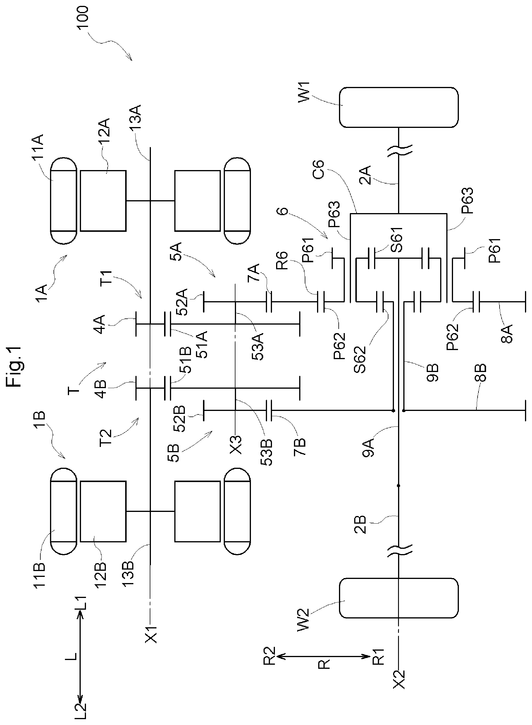
is a single line diagram of a vehicle drive device according to an embodiment.
is a cross-sectional diagram of the vehicle drive device according to the embodiment.
is a plan view of a part of the vehicle drive device according to the embodiment.
is a perspective view of a part of the vehicle drive device according to the embodiment.
is a side view of a part of the vehicle drive device according to the embodiment.
is a perspective view in which a case of the vehicle drive device according to the embodiment is seen through.
is a perspective view in which the case of the vehicle drive device according to the embodiment is seen through.
is a front view of the vehicle drive device according to the embodiment.
is a single line diagram of a vehicle drive device according to another embodiment.
DETAILED DESCRIPTION
An embodiment of a vehicle drive device will be described with reference to the drawings. In this embodiment, a first rotating electric machine 1 A corresponds to a “first driving force source”, a second rotating electric machine 1 B corresponds to a “second driving force source”, a first input gear 4 A corresponds to a “first gear”, a second input gear 4 B corresponds to a “second gear”, a first differential input gear 7 A corresponds to a “first outer gear”, a second differential input gear 7 B corresponds to a “second outer gear”, a second oil passage 24 B corresponds to an “oil passage connecting an oil pump to an oil cooler”, a third oil passage 24 C corresponds to an “oil passage connecting the oil cooler to the first driving force source and the second driving force source”, a first counter input gear 51 A corresponds to a “third gear”, a second counter input gear 51 B corresponds to a “fifth gear”, a first counter output gear 52 A corresponds to a “fourth gear”, and a second counter output gear 52 B corresponds to a “sixth gear”.
In this specification, the term “rotating electric machine” is used as a concept that includes a motor (electric motor), a generator (generator), and a motor-generator that performs the functions of both a motor and a generators as necessary.
In this specification, “overlapping as viewed in a specific direction” regarding disposal of two members means that when a virtual straight line parallel to the viewing direction is moved in any direction orthogonal to this virtual straight line, a region where the virtual straight line intersects both of the two members exists, at least in part. In this specification, “regions in the axial direction in which two members are disposed overlapping each other” regarding disposal of two members means that the region in the axial direction where one member is disposed includes at least a part of the region in the axial direction where the other member is disposed.
In this specification, “being drivably coupled” refers to a state where two rotating elements are coupled in such a manner as to be capable of transmitting driving force, and includes a state where the two rotating elements are coupled in such a manner as to be capable of rotating integrally, or a state where the two rotating elements are coupled in such a manner as to be capable of transmitting driving force via one or more transmission members. Examples of the transmission members include various members (e.g. shafts, gear mechanisms, belts, chains etc.) that transmit rotation at the same speed or at variable speeds. Note that the transmission members may also include an engagement device (e.g. friction engagement device, intermeshing engagement device etc.) that selectively transmits rotation and driving force. However, when the expression “being drivably coupled” is used regarding rotating elements of a differential gear mechanism, this expression refers to a state where three or more rotating elements included in the differential gear mechanism are drivably coupled, not via any other rotating element.
A vehicle drive device 100 includes a first rotating electric machine 1 A, a second rotating electric machine 1 B, a first output member 2 A that is drivably coupled to a first wheel W 1 , a second output member 2 B that is drivably coupled to a second wheel W 2 , and a motive power transmission mechanism T, as shown in . The vehicle drive device 100 also includes a case 3 that accommodates the first rotating electric machine 1 A, the second rotating electric machine 1 B, the first output member 2 A, the second output member 2 B, and the motive power transmission mechanism T, as shown in . In the example shown in , a part of the first output member 2 A and a part of the second output member 2 B are exposed outside the case 3 .
The first wheel W 1 and the second wheel W 2 are a pair of left and right wheels (e.g. a pair of left and right front wheels or a pair of left and right rear wheels) of a vehicle (a vehicle in which the vehicle drive device 100 is mounted). The first output member 2 A of this embodiment is coupled to the first wheel W 1 in an integrally rotatable manner, and the second output member 2 B is coupled to the second wheel W 2 in an integrally rotatable manner. The first output member 2 A is coupled to the first wheel W 1 via a constant velocity joint, for example, and the second output member 2 B is coupled to the second wheel W 2 via a constant velocity joint, for example.
The motive power transmission mechanism T includes a first transmission system T 1 that transmits torque of the first rotating electric machine 1 A to at least the first output member 2 A, and a second transmission system T 2 that transmits torque of the second rotating electric machine 1 B to at least the second output member 2 B, as shown in . The vehicle drive device 100 causes the vehicle to travel by transmitting torque of the first rotating electric machine 1 A to at least the first output member 2 A and transmitting torque of the second rotating electric machine 1 B to at least the second output member 2 B. The first rotating electric machine 1 A and the second rotating electric machine 1 B are electrically connected to a power storage device (not shown) via a later-described inverter unit 90 . The first rotating electric machine 1 A and the second rotating electric machine 1 B are powered by electric power supplied from the power storage device, or supply electric power generated by the inertia of the vehicle, for example, to the power storage device, which stores the supplied power. The first rotating electric machine 1 A and the second rotating electric machine 1 B of this embodiment are independently rotatable relative to each other.
The first transmission system T 1 of this embodiment transmits torque of the first rotating electric machine 1 A to the first output member 2 A and the second output member 2 B, and the second transmission system T 2 transmits torque of the second rotating electric machine 1 B to the first output member 2 A and the second output member 2 B. That is, a portion of the first transmission system T 1 on the side opposite to the first rotating electric machine 1 A side and a portion of the second transmission system T 2 on the side opposite to the second rotating electric machine 1 B side are constituted by a common transmission system. The motive power transmission mechanism T distributes and transmit torque of the first rotating electric machine 1 A and torque of the second rotating electric machine 1 B to the first output member 2 A and the second output member 2 B.
The first rotating electric machine 1 A and the second rotating electric machine 1 B are disposed on a first axis X 1 , and the first output member 2 A and the second output member 2 B are disposed on a second axis X 2 , which is different from the first axis X 1 . The first axis X 1 and the second axis X 2 are parallel to each other. Here, an axial direction L refers to a direction parallel to the first axis X 1 and the second axis X 2 . A first side L 1 in the axial direction L refers to a side in the axial direction L on which the first rotating electric machine 1 A is disposed relative to the second rotating electric machine 1 B, and a second side L 2 in the axial direction L refers to the side opposite to the first side L 1 in the axial direction L. The first transmission system T 1 of this embodiment includes a first counter gear mechanism 5 A, and the second transmission system T 2 includes a second counter gear mechanism 5 B. The first counter gear mechanism 5 A and the second counter gear mechanism 5 B are disposed on a third axis X 3 , which is different from the first axis X 1 and the second axis X 2 . The first axis X 1 , the second axis X 2 , and the third axis X 3 are parallel to each other. The first axis X 1 , the second axis X 2 , and the third axis X 3 are virtual axes.
The vehicle drive device 100 of this embodiment is mounted in the vehicle with the axial direction L parallel to the left-right direction of the vehicle. Specifically, the vehicle drive device 100 is mounted in the vehicle such that the first side L 1 in the axial direction L coincides with the left side of the vehicle, and the second side L 2 in the axial direction L coincides with the right side of the vehicle. A width direction H refers to a direction orthogonal to the axial direction L as viewed in the up-down direction V (as viewed in a direction parallel to the up-down direction V (vertical direction)) with the vehicle drive device 100 mounted in the vehicle, as shown in . Further, a first side H 1 in the width direction H refers to one side in the width direction H, and a second side H 2 in the width direction H refers to the other side in the width direction H. Specifically, the first side H 1 in the width direction H refers to the side in the width direction H on which the first axis X 1 is located relative to the second axis X 2 , and the second side H 2 in the width direction H refers to the side opposite to the first side H 1 in the width direction H. The width direction H of this embodiment coincides with the front-rear direction of the vehicle. Specifically, the first side H 1 in the width direction H coincides with the rear side of the vehicle, and the second side H 2 in the width direction H coincides with the front side of the vehicle.
The first rotating electric machine 1 A includes a first stator 11 A fixed to the case 3 , and a first rotor 12 A rotatably supported relative to the first stator 11 A, as shown in . The second rotating electric machine 1 B includes a second stator 11 B fixed to the case 3 , and a second rotor 12 B rotatably supported relative to the second stator 11 B. Thus, the first rotating electric machine 1 A that includes the first rotor 12 A serves as a first driving force source that outputs torque transmitted by the first transmission system T 1 , and the second rotating electric machine 1 B that includes the second rotor 12 B serves as a second driving force source that outputs torque transmitted by the second transmission system T 2 . The first rotating electric machine 1 A and the second rotating electric machine 1 B of this embodiment are rotating electric machines of an inner-rotor type. Thus, the first rotor 12 A is disposed inward in the radial direction of the first stator 11 A (a radial direction based on the first axis X 1 ), and the second rotor 12 B is disposed inward in the radial direction of the second stator 11 B (a radial direction based on the first axis X 1 ).
As shown in , in this embodiment, a first disposal region A 1 , which is a region in the axial direction L where the first rotating electric machine 1 A is disposed, coincides with the disposal region of the first stator 11 A in the axial direction L. A second disposal region A 2 , which is a region in the axial direction L where the second rotating electric machine 1 B is disposed, coincides with the disposal region of the second stator 11 B in the axial direction L. The first stator 11 A and the second stator 11 B each have a stator core 14 and a coil end section 15 protruding from the stator core 14 toward both sides in the axial direction L. The coil end section 15 on the first side L 1 in the axial direction L is constituted by a portion of a coil wound on the stator core 14 that protrudes from the stator core 14 toward the first side L 1 in the axial direction L. The coil end section 15 on the second side L 2 in the axial direction L is constituted by a portion of the coil wound on the stator core 14 that protrudes from the stator core 14 toward the second side L 2 in the axial direction L. The disposal region in the axial direction L where the first stator 11 A and the second stator 11 B are disposed is a region in the axial direction L between an end, on the first side L 1 in the axial direction L, of the coil end section 15 disposed on the first side L 1 in the axial direction L and an end, on the second side L 2 in the axial direction L, of the coil end section 15 disposed on the second side L 2 in the axial direction L.
In this embodiment, the outside diameter of the first rotating electric machine 1 A is equal to the outside diameter of the second rotating electric machine 1 B. Specifically, the outside diameter of the stator core 14 of the first stator 11 A is equal to the outside diameter of the stator core 14 of the second stator 11 B.
The first transmission system T 1 includes a first input gear 4 A that is coupled to the first rotor 12 A in an integrally rotatable manner. The second transmission system T 2 includes a second input gear 4 B that is coupled to the second rotor 12 B in an integrally rotatable manner. Specifically, the first rotor 12 A is coupled to a first rotor shaft 13 A in an integrally rotatable manner. The first input gear 4 A is located on an outer face of a portion of the first rotor shaft 13 A on the second side L 2 in the axial direction L relative to the first rotor 12 A. The second rotor 12 B is coupled to a second rotor shaft 13 B in an integrally rotatable manner. The second input gear 4 B is located on an outer face of a portion of the second rotor shaft 13 B on the first side L 1 in the axial direction L relative to the second rotor 12 B.
In this embodiment, the first transmission system T 1 includes the first counter gear mechanism 5 A, and the second transmission system T 2 includes the second counter gear mechanism 5 B, as mentioned above. The first counter gear mechanism 5 A includes a first counter input gear 51 A that meshes with the first input gear 4 A, and a first counter output gear 52 A that integrally rotates with the first counter input gear 51 A. The first counter output gear 52 A is coupled to the first counter input gear 51 A in an integrally rotatable manner, via a first counter shaft 53 A. The first counter output gear 52 A of this embodiment is disposed on the first side L 1 in the axial direction L relative to the first counter input gear 51 A. The second counter gear mechanism 5 B includes a second counter input gear 51 B that meshes with the second input gear 4 B, and a second counter output gear 52 B that integrally rotates with the second counter input gear 51 B. The second counter output gear 52 B is coupled to the second counter input gear 51 B in an integrally rotatable manner, via a second counter shaft 53 B. The second counter output gear 52 B of this embodiment is disposed on the second side L 2 in the axial direction L relative to the second counter input gear 51 B.
In this embodiment, the first transmission system T 1 includes a first differential input gear 7 A, and the second transmission system T 2 includes a second differential input gear 7 B. The first differential input gear 7 A is a gear that is disposed on the second axis X 2 and to which the rotation of the first rotating electric machine 1 A is input. The second differential input gear 7 B is a gear that is disposed on the second axis X 2 and to which the rotation of the second rotating electric machine 1 B is input. The first differential input gear 7 A of this embodiment is a gear meshing with the first counter output gear 52 A, and receives the input of rotation of the first rotating electric machine 1 A via the first counter gear mechanism 5 A. The second differential input gear 7 B of this embodiment is a gear meshing with the second counter output gear 52 B, and receives the input of rotation of the second rotating electric machine 1 B via the second counter gear mechanism 5 B. The first differential input gear 7 A of this embodiment has the same diameter as the second differential input gear 7 B.
The motive power transmission mechanism T of this embodiment distributes and transmits torque of the first rotating electric machine 1 A and torque of the second rotating electric machine 1 B to the first output member 2 A and the second output member 2 B, as mentioned above. Specifically, the motive power transmission mechanism T has a differential gear mechanism 6 that distributes torque of the first rotating electric machine 1 A transmitted to the first differential input gear 7 A and torque of the second rotating electric machine 1 B transmitted to the second differential input gear 7 B, to the first output member 2 A and the second output member 2 B. The differential gear mechanism 6 has four rotating elements, namely a first input rotating element that is drivably coupled to the first differential input gear 7 A, a second input rotating element that is drivably coupled to the second differential input gear 7 B, a first output rotating element that is drivably coupled to the first output member 2 A, and a second output rotating element that is drivably coupled to the second output member 2 B. The rotation speeds of these four rotation elements are in the descending order from the first input rotating element to the first output rotating element, the second output rotating element, and the second input rotating element.
Note that the order of rotation speed refers to the order of rotation speed when each rotating element is in a rotating state. The rotation speed of each rotating element varies with the rotation state of the differential gear mechanism 6 , but the order of rotation speed of the rotating elements is constant because the order of rotation speed is determined by the structure of the differential gear mechanism 6 . The order of rotation speed of the rotating elements is equal to the order in which in the rotating elements are disposed in a velocity diagram (also called an alignment diagram).
The differential gear mechanism 6 of this embodiment is a planetary gear system (specifically, a Ravigneaux planetary gear system) with four rotating elements. Specifically, the differential gear mechanism 6 includes four rotating elements, namely a first sun gear S 61 , a second sun gear S 62 , a carrier C 6 , and a ring gear R 6 . The carrier C 6 rotatably supports a first pinion gear P 61 and a second pinion gear P 62 , which integrally rotate with respect to each other, via a pinion shaft P 63 . The first pinion gear P 61 has a smaller diameter than the second pinion gear P 62 . The first pinion gear P 61 meshes with the first sun gear S 61 , and the second pinion gear P 62 meshes with the second sun gear S 62 and also meshes with the ring gear R 6 .
The ring gear R 6 is the first input rotating element that is drivably coupled to the first differential input gear 7 A. Here, the ring gear R 6 is coupled to the first differential input gear 7 A in an integrally rotatable manner. Specifically, the first differential input gear 7 A is located on an outer circumferential face of a first coupling member 8 A, and the ring gear R 6 is coupled to the first coupling member 8 A in an integrally rotatable manner.
The second sun gear S 62 is the second input rotating element that is drivably coupled to the second differential input gear 7 B. Here, the second sun gear S 62 is coupled to the second differential input gear 7 B in an integrally rotatable manner. Specifically, the second differential input gear 7 B is located on an outer circumferential face of a second coupling member 8 B, and the second sun gear S 62 is coupled to the second coupling member 8 B in an integrally rotatable manner, via a second coupling shaft 9 B.
The carrier C 6 is the first output rotating element that is drivably coupled to the first output member 2 A. Here, the carrier C 6 is coupled to the first output member 2 A in an integrally rotatable manner. The first sun gear S 61 is the second output rotating element that is drivably coupled to the second output member 2 B. Here, the first sun gear S 61 is coupled to the second output member 2 B in an integrally rotatable manner. Specifically, the first sun gear S 61 is coupled to the second output member 2 B in an integrally rotatable manner, via a first connecting shaft 9 A.
The vehicle drive device 100 includes a case 3 . The case 3 of this embodiment includes a case body member 30 , a first cover member 31 A, and a second cover member 31 B, as shown in to 4 . The case body member 30 , the first cover member 31 A, and the second cover member 31 B are joined to each other, and are joined to each other with use of bolts in this embodiment.
The first cover member 31 A is disposed on the first side L 1 in the axial direction L relative to the case body member 30 , and is joined to the case body member 30 at a first joint J 1 . The first cover member 31 A is joined to the case body member 30 in such a manner as to close an opening section of the case body member 30 on the first side L 1 in the axial direction L. The second cover member 31 B is disposed on the second side L 2 in the axial direction L relative to the case body member 30 , and is joined to the case body member 30 at a second joint J 2 . The second cover member 31 B is joined to the case body member 30 in such a manner as to close an opening section of the case body member 30 on the second side L 2 in the axial direction L.
A space surrounded by the case body member 30 , the first cover member 31 A, and the second cover member 31 B accommodates the first rotating electric machine 1 A, the second rotating electric machine 1 B, the first output member 2 A, the second output member 2 B, and the motive power transmission mechanism T. That is, the case 3 includes a first containment chamber 70 A that accommodates the first rotating electric machine 1 A, the second rotating electric machine 1 B, the first output member 2 A, the second output member 2 B, and the motive power transmission mechanism T. The first containment chamber 70 A is surrounded by the case body member 30 , the first cover member 31 A, and the second cover member 31 B. The first containment chamber 70 A of this embodiment also accommodates a later-described oil pump 20 .
The case 3 of this embodiment includes a supporter 44 , as shown in . The supporter 44 has a wall shape extending along a plane orthogonal to the axial direction L, for example. The supporter 44 may be a part of the case body member 30 or a separate member from the case body member 30 . The supporter 44 is disposed between the first rotating electric machine 1 A and the second rotating electric machine 1 B in the axial direction L. In this embodiment, the supporter 44 is disposed in a middle area between the first rotating electric machine 1 A and the second rotating electric machine 1 B in the axial direction L. The first rotating electric machine 1 A, the first counter gear mechanism 5 A, and the first differential input gear 7 A are accommodated in a section of the first containment chamber 70 A on the first side L 1 in the axial direction L relative to the supporter 44 . The second rotating electric machine 1 B, the second counter gear mechanism 5 B, and the second differential input gear 7 B are accommodated in a section of the first containment chamber 70 A on the second side L 2 in the axial direction L relative to the supporter 44 . The differential gear mechanism 6 of this embodiment is accommodated in a section of the first containment chamber 70 A on the first side L 1 in the axial direction L relative to the supporter 44 .
The vehicle drive device 100 includes an inverter unit 90 that drives the first rotating electric machine 1 A and the second rotating electric machine 1 B, as shown in . Although the inverter unit 90 is simplified in , the inverter unit 90 includes an inverter (inverter circuit) that converts electric power between DC power and AC power, and components associated with the inverter. The inverter is, for example, a power module that includes a plurality of modularized elements (switching elements etc.). The components associated with the inverter are, for example, a first terminal block 91 A and a second terminal block 91 B shown in to 4 , a control board with a controller for controlling the inverter mounted thereon, a smoothing capacitor that smooths the voltage across positive and negative electrodes on the DC side of the inverter, or the like.
The first axis X 1 is located on the upper side V 1 relative to the second axis X 2 and on one side in the width direction H (specifically, on the first side H 1 in the width direction H) relative to the second axis X 2 , as shown in . The first rotating electric machine 1 A and the second rotating electric machine 1 B are spaced apart from each other in the axial direction L, as shown in . As shown in , the inverter unit 90 is disposed between the first rotating electric machine 1 A and the second rotating electric machine 1 B in the axial direction L in such a manner as to overlap the first rotating electric machine 1 A and the second rotating electric machine 1 B as viewed in the axial direction L (as viewed in a direction parallel to the axial direction L). Further, the inverter unit 90 is disposed on the upper side V 1 relative to the second axis X 2 in such a manner as to overlap at least some of the members disposed on the second axis X 2 as viewed in the up-down direction V.
In this vehicle drive device 100 , the first rotating electric machine 1 A and the second rotating electric machine 1 B are disposed on the same axis and spaced apart in the axial direction L. Thus, a region between the first rotating electric machine 1 A and the second rotating electric machine 1 B in the axial direction L that overlaps the first rotating electric machine 1 A and the second rotating electric machine 1 B as viewed in the axial direction L is likely to be a dead space. In addition, a region on the upper side V 1 relative to the second axis X 2 is also likely to be a dead space since the first axis X 1 is located on the upper side V 1 relative to the second axis X 2 and on the first side H 1 in the width direction H relative to the second axis X 2 . In the vehicle drive device 100 , in which the inverter unit 90 is disposed as described above, the inverter unit 90 can be disposed with use of the two regions that are likely to be dead spaces, thus preventing an increase in the size of the vehicle drive device 100 due to disposing the inverter unit 90 . Particularly, the disposal region of the inverter unit 90 as viewed in the up-down direction V can be widely secured by using the region between the first rotating electric machine 1 A and the second rotating electric machine 1 B in the axial direction L and the region on the upper side V 1 relative to the second axis X 2 as a disposal region of the inverter unit 90 . This makes it easier to keep small the dimensions the disposal region of the inverter unit 90 in the up-down direction. The inverter unit 90 can thus be disposed in an upper section of the vehicle drive device 100 while preventing an increase in the size of the vehicle drive device 100 in the up-down direction V.
The inverter unit 90 of this embodiment overlaps at least portions of the first rotating electric machine 1 A and the second rotating electric machine 1 B that are disposed on the upper side V 1 relative to the first axis X 1 , as viewed in the axial direction L (see ). The inverter unit 90 of this embodiment is disposed on the upper side V 1 relative to the first differential input gear 7 A and the second differential input gear 7 B in such a manner as to overlap the first differential input gear 7 A and the second differential input gear 7 B as viewed in the up-down direction V, as is clear from the positional relationship in the axial direction L between the inverter unit 90 and the first differential input gear 7 A and between the inverter unit 90 and the second differential input gear 7 B shown in , and the positional relationship in the up-down direction V between the inverter unit 90 and the first differential input gear 7 A shown in . That is, in this embodiment, “at least some of the members disposed on the second axis X 2 ” mentioned above include the first differential input gear 7 A and the second differential input gear 7 B. Also, the inverter unit 90 of this embodiment is disposed on the upper side V 1 relative to the second axis X 2 in such a manner as to overlap the second axis X 2 as viewed in the up-down direction V.
The inverter unit 90 of this embodiment is accommodated in the case 3 . That is, the case 3 includes a second containment chamber 70 B that accommodates the inverter unit 90 , in addition to the aforementioned first containment chamber 70 A. Specifically, the case 3 includes a third cover member 31 C in addition to the case body member 30 , the first cover member 31 A, and the second cover member 31 B, as shown in , 5 , and 8 . The third cover member 31 C is located on the upper side V 1 relative to the case body member 30 and is joined to the case body member 30 in such a manner as to close an opening section (see ) of the case body member 30 that faces toward the upper side V 1 . The third cover member 31 C of this embodiment is joined to the case body member 30 with use of bolts. The inverter unit 90 is accommodated in a space surrounded by the case body member 30 and the third cover member 31 C. That is, the second containment chamber 70 B is surrounded by the case body member 30 and the third cover member 31 C.
The case body member 30 includes a first side wall 40 A constituting a side wall of the second containment chamber 70 B on the first side L 1 in the axial direction L, a second side wall 40 B constituting a side wall of the second containment chamber 70 B on the second side L 2 in the axial direction L, a third side wall 40 C constituting a side wall of the second containment chamber 70 B on the first side H 1 in the width direction H, and a fourth side wall 40 D constituting a side wall of the second containment chamber 70 B on the second side H 2 in the width direction H, as shown in . The first side wall 40 A, the second side wall 40 B, the third side wall 40 C and the fourth side wall 40 D are integrated with the case body member 30 . A portion of the first side wall 40 A on the second side H 2 in the width direction H is disposed further on the first side L 1 in the axial direction L relative to a portion of the first side wall 40 A on the first side H 1 in the width direction H, and forms a later-described first region 72 A. A portion of the second side wall 40 B on the second side H 2 in the width direction H is disposed further on the second side L 2 in the axial direction L relative to a portion of the second side wall 40 B on the first side H 1 in the width direction H, and forms a later-described second region 72 B.
The second containment chamber 70 B is surrounded by the first side wall 40 A, the second side wall 40 B, the third side wall 40 C, the fourth side wall 40 D, a later-described third partition wall 61 C, and the third cover member 31 C. Thus, the third partition wall 61 C of this embodiment constitutes a bottom wall of the second containment chamber 70 B. In this embodiment, a portion of the third partition wall 61 C on the first side H 1 in the width direction H is disposed on the lower side V 2 relative to a portion of the third partition wall 61 C on the second side H 2 in the width direction H, and the second containment chamber 70 B is deeper in a section on the first side H 1 in the width direction H than a section on the second side H 2 in the width direction H. Further, the third side wall 40 C of this embodiment (specifically, a lower portion of the third side wall 40 C) is inclined toward the second side H 2 in the width direction H while extending toward the lower side V 2 .
The case body member 30 of this embodiment has, in an integrated manner, a partition wall section 60 , a first containment chamber section 62 A, and a second containment chamber section 62 B. That is, the case body member 30 includes the partition wall section 60 , the first containment chamber section 62 A, and the second containment chamber section 62 B. This case body member 30 is, for example, a casting produced by means of integral molding technology with use of casting.
The partition wall section 60 is a section that forms a partition wall demarcating the first containment chamber 70 A and the second containment chamber 70 B. In this embodiment, one partition wall demarcates the first containment chamber 70 A and the second containment chamber 70 B on the first side L 1 in the axial direction L, the second side L 2 in the axial direction L, and the lower side, as will be described below. Specifically, the first partition wall 61 A demarcates, in the axial direction L, a portion of the first containment chamber 70 A that is disposed on the first side L 1 in the axial direction L relative to the second containment chamber 70 B (where the first rotating electric machine 1 A is accommodated), and the second containment chamber 70 B, as shown in to 4 . Here, a part of the first side wall 40 A in the width direction H (specifically, a middle portion in the width direction H) constitutes the first partition wall 61 A. The second partition wall 61 B demarcates, in the axial direction L, a portion of the first containment chamber 70 A that is disposed on the second side L 2 in the axial direction L relative to the second containment chamber 70 B (where the second rotating electric machine 1 B is accommodated), and the second containment chamber 70 B. Here, a part of the second side wall 40 B in the width direction H (specifically, a middle portion in the width direction H) constitutes the second partition wall 61 B. The third partition wall 61 C demarcates, in the up-down direction V, a portion of the first containment chamber 70 A that is disposed on the lower side V 2 relative to the second containment chamber 70 B, and the second containment chamber 70 B. The partition wall section 60 forms these three partition walls (specifically, the first partition wall 61 A, the second partition wall 61 B, and the third partition wall 61 C).
The first containment chamber section 62 A is a portion that is other than the partition wall section 60 and forms at least a part of the first containment chamber 70 A. The first containment chamber section 62 A of this embodiment forms a part of the first containment chamber 70 A, as will be described below. The case 3 has a peripheral wall section that has a cylindrical shape extending in the axial direction L and surrounds the first rotating electric machine 1 A (and also surrounds the differential gear mechanism 6 in this embodiment), as shown in to 5 . The first containment chamber section 62 A forms a portion of the peripheral wall section on the second side L 2 in the axial direction L (specifically, a portion of the peripheral wall section on the second side L 2 in the axial direction L relative to the first joint J 1 ). The case 3 also has a peripheral wall section that has a cylindrical shape extending in the axial direction L and surrounds the second rotating electric machine 1 B (and also surrounds the oil pump 20 in this embodiment). The first containment chamber section 62 A forms a portion of the peripheral wall section on the first side L 1 in the axial direction L (specifically, a portion of the peripheral wall section on the first side L 1 in the axial direction L relative to the second joint J 2 ). The case 3 also has a peripheral wall section (later-described peripheral wall section 42 ) that has a cylindrical shape extending in the axial direction L and surrounds the first differential input gear 7 A and the second differential input gear 7 B. The first containment chamber section 62 A forms a part of the peripheral wall section 42 (specifically, a portion of the peripheral wall section 42 that is not included in the third partition wall 61 C).
The second containment chamber section 62 B is a portion that is other than the partition wall section 60 and forms at least a part of the second containment chamber 70 B. In this embodiment, the second containment chamber section 62 B forms portions of the first side wall 40 A that do not constitute the first partition wall 61 A (here, portions of the first side wall 40 A on both sides in the width direction H), portions of the second side wall 40 B that do not constitute the second partition wall 61 B (here, portions of the second side wall 40 B on both sides in the width direction H), the third side wall 40 C, and the fourth side wall 40 D, as shown in to 5 .
Thus, the vehicle drive device 100 of this embodiment includes the case 3 , which includes the first containment chamber 70 A accommodating the first rotating electric machine 1 A, the second rotating electric machine 1 B, the first output member 2 A, the second output member 2 B, and the motive power transmission mechanism T, and the second containment chamber 70 B accommodating the inverter unit 90 . The case 3 includes the case body member 30 integrated with the partition wall section 60 , which is a portion forming the partition walls (in this example, the first partition wall 61 A, the second partition wall 61 B, and the third partition wall 610 that demarcate the first containment chamber 70 A and the second containment chamber 70 B), the portion (first containment chamber section 62 A) that is other than the partition wall section 60 and forms at least a part of the first containment chamber 70 A, and the portion (second containment chamber section 62 B) that is other than the partition wall section 60 and forms at least a part of the second containment chamber 70 B.
In the vehicle drive device 100 of this embodiment, the portion that forms at least a part of the first containment chamber 70 A and the portion that forms at least a part of the second containment chamber 70 B are also formed in the member in which the partition wall section 60 is formed. This makes it easier to keep the number of components of the case 3 smaller than in the case where these two portions are not formed in the member in which the partition wall section 60 is formed. The size of the vehicle drive device 100 can be reduced by reducing the number of components of the case 3 and thus reducing the number of joints in the case 3 .
In the vehicle drive device 100 of this embodiment, one partition wall formed by the partition wall section 60 can demarcate the first containment chamber 70 A and the second containment chamber 70 B. In the case where the first containment chamber 70 A and the second containment chamber 70 B are demarcated by two or more partition walls next to each other in the wall thickness direction, gaps between the partition walls can increase the size of the vehicle drive device 100 . In contrast, one partition wall can demarcate the first containment chamber 70 A and the second containment chamber 70 B in the vehicle drive device 100 of this embodiment, making it easier to reduce the size of the vehicle drive device 100 . Further, in the case where the connection path that electrically connects the inverter unit 90 to a rotating electric machine (specifically, each of the first rotating electric machine 1 A and the second rotating electric machine 1 B) extends through a through-hole in the partition wall, a sealing member is usually provided to seal the gap in the through-hole. If two or more partition walls next to each other in the wall thickness direction demarcate the first containment chamber 70 A and the second containment chamber 70 B, each of these partition walls needs to have a through-hole. The vehicle drive device 100 of this embodiment need only have a through-hole in one partition wall, making it easier to keep the number of sealing members small.
The vehicle drive device 100 of this embodiment includes the case 3 . The case 3 includes the first containment chamber 70 A accommodating the first rotating electric machine 1 A, the second rotating electric machine 1 B, the first output member 2 A, the second output member 2 B, and the motive power transmission mechanism T, and the second containment chamber 70 B accommodating the inverter unit 90 . With the first side H 1 in the width direction H referring to the side in the width direction H on which the first axis X 1 is located relative to the second axis X 2 , and the second side H 2 in the width direction H referring to the side opposite to the first side H 1 in the width direction H, the second containment chamber 70 B has a first section 71 A, which is a section sandwiched between the first rotating electric machine 1 A and the second rotating electric machine 1 B in the axial direction L, and a second section 71 B, which is a section on the second side H 2 in the width direction H relative to the first section 71 A, as shown in . The second section 71 B of this embodiment has a larger dimension in the axial direction L than the first section 71 A. In this embodiment, a part of the second section 71 B overlaps the first containment chamber 70 A as viewed in the width direction H (as viewed in a direction parallel to the width direction H), as shown in .
In the vehicle drive device 100 of this embodiment, the second section 71 B is less constrained in terms of the dimension in the axial direction L than the first section 71 A that is sandwiched between the first rotating electric machine 1 A and the second rotating electric machine 1 B in the axial direction L. The region where the second containment chamber 70 B is formed as viewed in the up-down direction V can be expanded by increasing the dimension of the second section 71 B in the axial direction L as mentioned above. Note that a part of the second section 71 B overlaps the first containment chamber 70 A as viewed in the width direction H. This can expand the region where the second containment chamber 70 B is formed as viewed in the up-down direction V, while preventing an increase in the size of the vehicle drive device 100 in the up-down direction V. Further, thus expanding the region where the second containment chamber 70 B is formed as viewed in the up-down direction V makes it possible to keep small the dimension of the second containment chamber 70 B in the up-down direction V that is required to accommodate the inverter unit 90 . Accordingly, the inverter unit 90 can be disposed in an upper part of the vehicle drive device 100 while preventing an increase in the size of the vehicle drive device 100 in the up-down direction V.
In this embodiment, a portion of the second section 71 B on the first side L 1 in the axial direction L (a later-described first region 72 A) overlaps a portion of the first containment chamber 70 A that accommodates the first rotating electric machine 1 A as viewed in the width direction H. A portion of the second section 71 B on the second side L 2 in the axial direction L (a later-described second region 72 B) overlaps a portion of the first containment chamber 70 A that accommodates the second rotating electric machine 1 B as viewed in the width direction H.
With the first side L 1 in the axial direction L referring to the side in the axial direction L on which the first rotating electric machine 1 A is disposed relative to the second rotating electric machine 1 B, and the second side L 2 in the axial direction L referring to the side opposite to the first side L 1 in the axial direction L, the second section 71 B of this embodiment has a first region 72 A, which is a region extended toward the first side L 1 in the axial direction L relative to the first section 71 A, and a second region 72 B, which is a region extended toward the second side L 2 in the axial direction L relative to the first section 71 A, as shown in . Specifically, the second section 71 B has a third region 72 C, which is a region extended toward the second side H 2 in the width direction H relative to the first section 71 A. The first region 72 A is a region of the second section 71 B on the first side L 1 in the axial direction L relative to the third region 72 C. The second region 72 B is a region of the second section 71 B on the second side L 2 in the axial direction L relative to the third region 72 C. In this embodiment, the first terminal block 91 A for electrically connecting the inverter unit 90 to the first rotating electric machine 1 A is disposed in the first region 72 A. The second terminal block 91 B for electrically connecting the inverter unit 90 to the second rotating electric machine 1 B is disposed in the second region 72 B.
In the vehicle drive device 100 of this embodiment, it is possible to dispose the first terminal block 91 A at a position in the axial direction L at which the first terminal block 91 A can be easily electrically connected to the first rotating electric machine 1 A, and dispose the second terminal block 91 B at a position in the axial direction L at which the second terminal block 91 B can be easily electrically connected to the second rotating electric machine 1 B, while giving consideration to the positional relationship in the axial direction L between the first rotating electric machine 1 A and the second rotating electric machine 1 B, as mentioned above. Further, in the vehicle drive device 100 of this embodiment, the first terminal block 91 A and the second terminal block 91 B can be disposed in such a manner as to avoid a central region (third region 72 C) that is a region of the second section 71 B that is extended toward the second side H 2 in the width direction H relative to the first section 71 A. It is thus possible to dispose constituent elements of the inverter unit 90 other than the first terminal block 91 A and the second terminal block 91 B, in a region continuous in the width direction H, including the first section 71 A and the central area (third region 72 C) of the second section 71 B, thus making it easier to appropriately dispose the constituent elements of the inverter unit 90 within the second containment chamber 70 B.
The first terminal block 91 A and the second terminal block 91 B each have inverter-side terminals 92 that are electrically connected to an inverter (inverter circuit) included in the inverter unit 90 , as shown in to 4 . The inverter is electrically connected to the first terminal block 91 A and the second terminal block 91 B within the second containment chamber 70 B. The first terminal block 91 A and second terminal block 91 B each have a rotating electric machine-side terminal 93 that is electrically connected to the corresponding rotating electric machine, as shown in . The inverter-side terminals 92 and the rotating electric machine-side terminal 93 of the first terminal block 91 A are electrically connected to each other. The inverter-side terminals 92 and the electric machine-side terminal 93 of the second terminal block 91 B are electrically connected to each other. Although only shows the second terminal block 91 B, the first terminal block 91 A has the same rotating electric machine-side terminal 93 as the rotating electric machine-side terminal 93 of the second terminal block 91 B. The rotating electric machine-side terminal 93 of the first terminal block 91 A is electrically connected to the first rotating electric machine 1 A (e.g. a bus bar connected to a coil of the first stator 11 A) within the first containment chamber 70 A. The rotating electric machine-side terminal 93 of the second terminal block 91 B is electrically connected to the second rotating electric machine 1 B (e.g. a bus bar connected to a coil of the second stator 11 B) within the first containment chamber 70 A.
The first terminal block 91 A and the second terminal block 91 B extend through the partition wall (specifically, the third partition wall 61 C) that demarcates the first containment chamber 70 A and the second containment chamber 70 B. That is, the connection path that electrically connects the inverter unit 90 to the first rotating electric machine 1 A and the connection path that electrically connects the inverter unit 90 to the second rotating electric machine 1 B pass through respective through-holes (see ) in the third partition wall 61 C. Although details are omitted, a through-hole through which the first terminal block 91 A is inserted is provided with a sealing member that seals the gap in the through-hole, and a through-hole through which the second terminal block 91 B is inserted is provided with a sealing member that seals the gap in the through-hole.
The case 3 has a first surrounding wall 41 A, which is a wall surrounding the first rotating electric machine 1 A, and a second surrounding wall 41 B, which is a wall surrounding the second rotating electric machine 1 B, as shown in to 5 . In this embodiment, the first surrounding wall 41 A is constituted by a portion of the case body member 30 on the first side L 1 in the axial direction L, and the first cover member 31 A. The second surrounding wall 41 B is constituted by a portion of the case body member 30 on the second side L 2 in the axial direction L, and the second cover member 31 B.
The first surrounding wall 41 A has a first peripheral wall section, a first wall section, and a second wall section. The first peripheral wall section is a wall section that has a cylindrical shape extending in the axial direction L and surrounds the first rotating electric machine 1 A (and also surrounds the differential gear mechanism 6 in this embodiment). In this embodiment, a portion of the first peripheral wall section on the first side L 1 in the axial direction L is constituted by the first cover member 31 A, and a portion of the first peripheral wall section on the second side L 2 in the axial direction L is constituted by the case body member 30 . The first wall section is a wall section that closes an opening section of the first peripheral wall section on the first side L 1 in the axial direction L. The first cover member 31 A forms the first wall of this embodiment. The first wall (first cover member 31 A) has a through-hole, and the first output member 2 A is disposed in this through-hole. The second wall section is a wall section that closes a part of the opening section of the first peripheral wall section on the second side L 2 in the axial direction L, and faces the first rotating electric machine 1 A in the axial direction L, on the second side L 2 in the axial direction L relative to the first rotating electric machine 1 A. The case body member 30 (specifically, a portion of the case body member 30 that includes the first partition wall 61 A) forms the second wall of this embodiment.
The second surrounding wall 41 B has a second peripheral wall section, a third wall section, and a fourth wall section. The second peripheral wall section is a wall section that has a cylindrical shape extending in the axial direction L and surrounds the second rotating electric machine 1 B (and also surrounds the oil pump 20 in this embodiment). In this embodiment, a portion of the second peripheral wall section on the second side L 2 in the axial direction L is constituted by the second cover member 31 B, and a portion of the second peripheral wall section on the first side L 1 in the axial direction L is constituted by the case body member 30 . The third wall section is a wall section that closes an opening section of the second peripheral wall section on the second side L 2 in the axial direction L. The second cover member 31 B forms the third wall of this embodiment. The third wall (second cover member 31 B) has a through-hole, and the second output member 2 B is disposed in this through-hole. The fourth wall section is a wall section that closes a part of the opening section of the second peripheral wall section on the first side L 1 in the axial direction L, and faces the second rotating electric machine 1 B in the axial direction L, on the first side L 1 in the axial direction L relative to the second rotating electric machine 1 B. The case body member 30 (specifically, a portion of the case body member 30 that includes the second partition wall 61 B) forms the fourth wall of this embodiment.
The first surrounding wall 41 A and the second surrounding wall 41 B are spaced apart from each other in the axial direction L. Thus, a recessed section (a portion where the second containment chamber 70 B is formed) is formed in a portion of the case 3 (specifically, the case body member 30 ) between the first surrounding wall 41 A and the second surrounding wall 41 B in the axial direction L. In this embodiment, a portion of the case 3 that forms at least a part of the second containment chamber 70 B serves as a reinforcing rib that increases the rigidity of the recessed section. Specifically, the third side wall 40 C and the fourth side wall 40 D of the second containment chamber 70 B join the first surrounding wall 41 A to the second surrounding wall 41 B in the axial direction L, and the third side wall 40 C and the fourth side wall 40 D (particularly, the third side wall 40 C) serve as reinforcing ribs.
The case 3 of this embodiment thus includes the first surrounding wall 41 A that is a wall surrounding the first rotating electric machine 1 A, the second surrounding wall 41 B that is a wall surrounding the second rotating electric machine 1 B, and joint walls (the third side wall 40 C and the fourth side wall 40 D in this example) that form at least parts of the second containment chamber 70 B and join the first surrounding wall 41 A to the second surrounding wall 41 B in the axial direction L.
In the vehicle drive device 100 of this embodiment, the joint walls (the third side wall 40 C and the fourth side wall 40 D in this example), which form at least parts of the second containment chamber 70 B, can serve as reinforcing ribs that increase the rigidity of the recessed section in the case 3 that is formed between the first surrounding wall 41 A and the second surrounding wall 41 B in the axial direction L. The joint walls for forming the second containment chamber 70 B can thus be used to reinforce the case 3 , thereby making it easier to appropriately ensure the rigidity of the case 3 .
The vehicle drive device 100 includes an oil pump 20 that supplies oil to the first rotating electric machine 1 A and the second rotating electric machine 1 B, and an oil cooler 22 that cools the oil, as shown in . For example, the oil pump 20 can be an electric oil pump driven by an electric motor. The type of the pump is not specifically limited, and may be a gear pump, a vane pump, a screw pump, or the like. The oil pump 20 of this embodiment is accommodated in the first containment chamber 70 A. A configuration may alternatively be employed in which the oil pump 20 is not accommodated in the first containment chamber 70 A (e.g. a configuration in which the oil pump 20 is attached to the outside of the case 3 ).
The oil pump 20 (specifically, an inlet of the oil pump 20 ) is connected, via a first oil passage 24 A, to a strainer 21 , which is a filter that removes foreign matter from the oil, as shown in . The oil pump 20 suctions oil stored in the case 3 through the strainer 21 . The oil pump 20 (specifically, an outlet of the oil pump 20 ) is connected to the oil cooler 22 via a second oil passage 24 B. The oil discharged from the oil pump 20 extends through the oil cooler 22 and is thereafter supplied to the first rotating electric machine 1 A and the second rotating electric machine 1 B. The first oil passage 24 A and the second oil passage 24 B are formed with oil pipes, for example.
The oil cooler 22 cools oil by means of heat exchange between the oil and a coolant (e.g. cooling water, air etc.). The oil cooler 22 of this embodiment is a water-cooling oil cooler that uses cooling water as a coolant. The oil cooler 22 is connected to a pipe member 23 for introducing the cooling water into the oil cooler 22 , and a pipe member 23 for discharging the cooling water from the oil cooler 22 , as shown in to 4 .
Here, a “first outer gear” refers to a gear disposed on the outermost side R 2 in the radial direction R (radial direction based on the second axis X 2 ) among gears disposed on the second axis X 2 and constituting the first transmission system T 1 (i.e. a gear with the largest diameter). A “second outer gear” refers to a gear disposed on the outermost side R 2 in the radial direction R among gears disposed on the second axis X 2 and constituting the second transmission system T 2 . In this embodiment, the first differential input gear 7 A is the first outer gear, and the second differential input gear 7 B is the second outer gear, as shown in . The first differential input gear 7 A and the second differential input gear 7 B are spaced apart from each other in the axial direction L. The oil cooler 22 is disposed between the first differential input gear 7 A and the second differential input gear 7 B in the axial direction L in such a manner as to overlap at least either the first differential input gear 7 A or the second differential input gear 7 B as viewed in the axial direction L, as shown in , 5 , and 7 .
In the vehicle drive device 100 , the first differential input gear 7 A and the second differential input gear 7 B are spaced apart from each other in the axial direction L. Thus, a region between the first differential input gear 7 A and the second differential input gear 7 B in the axial direction L that overlaps at least either the first differential input gear 7 A or the second differential input gear 7 B as viewed in the axial direction L is likely to be a dead space. In the vehicle drive device 100 , in which the oil cooler 22 is disposed as described above, the oil cooler 22 can be disposed using the region that is likely to be a dead space, thus making it possible to prevent an increase in the size of the vehicle drive device 100 due to disposing the oil cooler 22 .
In this embodiment, the oil cooler 22 is disposed on the second side H 2 in the width direction H relative to the second axis X 2 and between the first differential input gear 7 A and the second differential input gear 7 B in the axial direction L, in such a manner as to overlap at least either the first differential input gear 7 A or the second differential input gear 7 B as viewed in the axial direction L, as shown in . In this embodiment, the first differential input gear 7 A has the same diameter as the second differential input gear 7 B, and the oil cooler 22 overlaps both the first differential input gear 7 A and the second differential input gear 7 B as viewed in the axial direction L.
The case 3 has the peripheral wall section 42 that covers the outer side R 2 , in the radial direction R, of the first differential input gear 7 A and the second differential input gear 7 B, as shown in to 4 . The peripheral wall section 42 is a wall section continuous in the axial direction L. The peripheral wall section 42 has a portion covering the outer side R 2 of the first differential input gear 7 A in the radial direction R, a portion covering the outer side R 2 of the second differential input gear 7 B in the radial direction R, and a portion (hereinafter, “a target portion”) between these two portions in the axial direction L. The peripheral wall section 42 of this embodiment is constituted by the case body member 30 (specifically, the first containment chamber section 62 A and the third partition wall 61 C). The peripheral wall section 42 has a recessed section 43 that is recessed toward the inner side R 1 in the radial direction R in an area corresponding to the space between the first differential input gear 7 A and the second differential input gear 7 B in the axial direction L. That is, the recessed section 43 that is recessed toward the inner side R 1 in the radial direction R is formed in a part of the peripheral wall section 42 between the first differential input gear 7 A and the second differential input gear 7 B in the axial direction L (i.e. the aforementioned target portion). The recessed section 43 of this embodiment is recessed toward the first side H 1 in the width direction H in an area of the peripheral wall section 42 on the second side H 2 in the width direction H. At least a part of the oil cooler 22 is located within the recessed section 43 . That is, the oil cooler 22 is attached to the outside of the case 3 such that at least a part of the oil cooler 22 is located within the recessed section 43 . Here, “being located within the recessed section 43 ” means being covered by the peripheral wall section 42 as viewed in the axial direction L, regardless of which side in the axial direction L the oil cooler 22 is viewed from. In this embodiment, the entire body (where heat exchange between the oil and the coolant takes place) of the oil cooler 22 is located within the recessed section 43 .
As described above, the vehicle drive device 100 of this embodiment includes the case 3 that accommodates the first rotating electric machine 1 A, the second rotating electric machine 1 B, the first output member 2 A, the second output member 2 B, and the motive power transmission mechanism T. The case 3 has the peripheral wall section 42 that covers the outer side R 2 , in the radial direction R, of the first differential input gear 7 A and the second differential input gear 7 B. The recessed section 43 , which is recessed toward the inner side R 1 in the radial direction R, is formed in an area of the peripheral wall section 42 between the first differential input gear 7 A and the second differential input gear 7 B in the axial direction L. At least a part of the oil cooler 22 is located within the recessed section 43 .
The oil cooler 22 is often attached to the outside of the case 3 . In this case, the shape of the vehicle drive device 100 is likely to be such that a portion to which the oil cooler 22 is attached protrudes outward relative to the surrounding area, and the vehicle drive device 100 can become larger on the side on which the oil cooler 22 is attached. In the vehicle drive device 100 of this embodiment, the recessed section 43 is formed in the peripheral wall section 42 of the case 3 with use of the region between the first differential input gear 7 A and the second differential input gear 7 B in the axial direction L that is likely to be a dead space, and the oil cooler 22 can be disposed in such a manner that at least a part of the oil cooler 22 is located within the recessed section 43 . Thus, the oil cooler 22 can be attached to the outside of the case 3 while preventing an increase in the size of the vehicle drive device 100 .
In this the embodiment, the first disposal region A 1 , which is the disposal region of the first rotating electric machine 1 A in the axial direction L, overlaps a third disposal region A 3 , which is a disposal region of the differential gear mechanism 6 in the axial direction L, as shown in . The third disposal region A 3 in is the disposal region the carrier C 6 of the differential gear mechanism 6 in the axial direction L (the region between an edge of the carrier C 6 on the first side L 1 in the axial direction L and an edge thereof on the second side L 2 in the axial direction L, in the axial direction L). Further, in this the embodiment, the second disposal region A 2 , which is the disposal region of the second rotating electric machine 1 B in the axial direction L, overlaps a fourth disposal region A 4 , which is a disposal region of the oil pump 20 in the axial direction L. The oil cooler 22 of this embodiment overlaps at least either the differential gear mechanism 6 or the oil pump 20 as viewed in the axial direction L. The oil cooler 22 in this example overlaps the differential gear mechanism 6 and not overlap the oil pump 20 as viewed in the axial direction L (the oil pump 20 is omitted in ), as shown in . However, it is also possible to alternatively employ a configuration in which the oil cooler 22 overlaps the oil pump 20 and not overlap the differential gear mechanism 6 as viewed in the axial direction L, or a configuration in which the oil cooler 22 overlaps both the differential gear mechanism 6 and the oil pump 20 as viewed in the axial direction L.
In this embodiment, the first driving force source (the driving force source that outputs torque transmitted by the first transmission system T 1 ) is the first rotating electric machine 1 A that includes the first rotor 12 A, and the second driving force source (the driving force source that outputs torque transmitted by the second transmission system T 2 ) is the second rotating electric machine 1 B that includes the second rotor 12 B, as described above. The first transmission system T 1 includes the first input gear 4 A that is coupled to the first rotor 12 A in an integrally rotatable manner, and the first counter gear mechanism 5 A that includes the third gear meshing with the first gear and the fourth gear that integrally rotates with the third gear. The second transmission system T 2 includes the second input gear 4 B that is coupled to the second rotor 12 B in an integrally rotatable manner, and the second counter gear mechanism 5 B that includes the fifth gear meshing with the second gear and the sixth gear that integrally rotates with the fifth gear. The first differential input gear 7 A is a gear meshing with the first counter output gear 52 A, and the second differential input gear 7 B is a gear meshing with the second counter output gear 52 B. The motive power transmission mechanism T has the differential gear mechanism 6 , which distributes torque of the first rotating electric machine 1 A transmitted to the first differential input gear 7 A and torque of the second rotating electric machine 1 B transmitted to the second differential input gear 7 B, to the first output member 2 A and the second output member 2 B. The disposal regions of the first rotating electric machine 1 A and the differential gear mechanism 6 in the axial direction L overlap each other, and the disposal regions of the second rotating electric machine 1 B and the oil pump 20 in the axial direction L overlap each other. The oil cooler 22 overlaps at least either the differential gear mechanism 6 or the oil pump 20 as viewed in the axial direction L.
In the case where the first transmission system T 1 and the second transmission system T 2 are configured as described above, the diameters of the first differential input gear 7 A and the second differential input gear 7 B are likely to increase if the reduction ratio from the rotating electric machines to the first output member 2 A and the second output member 2 B is to be kept large. In the vehicle drive device 100 of this embodiment, the oil cooler 22 can be disposed with use of the region between the first differential input gear 7 A and the second differential input gear 7 B in the axial direction L that is likely to be a dead space, as described above. Therefore, even if the diameters of the first differential input gear 7 A and the second differential input gear 7 B are large, a further increase in the size of the vehicle drive device 100 due to disposing the oil cooler 22 can be prevented.
Furthermore, in the vehicle drive device 100 of this embodiment, the disposal regions of the first rotating electric machine 1 A and the differential gear mechanism 6 in the axial direction L overlap each other, and the disposal regions of the second rotating electric machine 1 B and the oil pump 20 in the axial direction L overlap each other. Thus separating the differential gear mechanism 6 and the oil pump 20 on the respective sides in the axial direction L can prevent an increase in the size of the vehicle drive device 100 on one side in the axial direction L than on the other side, and allows the vehicle drive device 100 to have a shape that can be easily mounted in a vehicle. Further, in the vehicle drive device 100 of this embodiment, the oil cooler 22 overlaps at least either the differential gear mechanism 6 or the oil pump 20 as viewed in the axial direction L, making it easier to keep small the dimension of the vehicle drive device 100 as viewed in the axial direction L.
In this the embodiment, the second oil passage 24 B, which is an oil passage connecting the oil pump 20 to the oil cooler 22 , extends through a region between the first differential input gear 7 A and the second differential input gear 7 B in the axial direction L and overlaps at least either (both in the example shown in ) the first differential input gear 7 A or the second differential input gear 7 B as viewed in the axial direction L, as shown in .
In the vehicle drive device 100 of this embodiment, the second oil passage 24 B, which is an oil passage connecting the oil pump 20 to the oil cooler 22 , is disposed as described above, thereby allowing the oil passage connecting the oil pump 20 to the oil cooler 22 to be also disposed with use of the region between the first differential input gear 7 A and the second differential input gear 7 B in the axial direction L that is likely to be a dead space. This makes it easy to reduce the size of the vehicle drive device 100 .
The second oil passage 24 B of this the embodiment extends through the region on the lower side V 2 relative to the second axis X 2 and between the first differential input gear 7 A and the second differential input gear 7 B in the axial direction L, the region overlapping at least either the first differential input gear 7 A or the second differential input gear 7 B as viewed in the axial direction L, as shown in . Meanwhile, a later-described third oil passage 24 C of this embodiment extends through a region on the upper side V 1 relative to the second axis X 2 and between the first differential input gear 7 A and the second differential input gear 7 B in the axial direction L, the region overlapping at least either the first differential input gear 7 A or the second differential input gear 7 B as viewed in the axial direction L, as shown in .
In this the embodiment, the third oil passage 24 C, which is an oil passage connecting the oil cooler 22 to both the first rotating electric machine 1 A and the second rotating electric machine 1 B, extends through a region between the first differential input gear 7 A and the second differential input gear 7 B in the axial direction L, the region overlapping at least either (both in the example shown in ) the first differential input gear 7 A or the second differential input gear 7 B as viewed in the axial direction L, as shown in .
In the vehicle drive device 100 of this the embodiment, the third oil passage 24 C, which is an oil passage connecting the oil cooler 22 to both the first rotating electric machine 1 A and the second rotating electric machine 1 B, is disposed as described above. Thus, the oil passage connecting the oil cooler 22 to both the first rotating electric machine 1 A and the second rotating electric machine 1 B can also be disposed with use of the region between the first differential input gear 7 A and the second differential input gear 7 B in the axial direction L that is likely to be a dead space. This makes it easy to reduce the size of the vehicle drive device 100 . Disposing the third oil passage 24 C as described above allows the oil passage connecting the oil cooler 22 to both the first rotating electric machine 1 A and the second rotating electric machine 1 B to be branched off from between the first rotating electric machine 1 A and the second rotating electric machine 1 B in the axial direction L (e.g. from a middle portion between the first rotating electric machine 1 A and the second rotating electric machine 1 B in the axial direction L) to both sides in the axial direction L and reach the first rotating electric machine 1 A and the second rotating electric machine 1 B. This makes it easy to make the length of the oil passage connecting the oil cooler 22 to the first rotating electric machine 1 A close to the length of the oil passage connecting the oil cooler 22 to the second rotating electric machine 1 B, and to equalize the pressure drop in these two oil passages. For example, the pressure drop in these two oil passages can be reduced to the same degree by keeping the lengths of the oil passages short to the same degree.
The following is a specific description of a configuration of the third oil passage 24 C in the vehicle drive device 100 of this embodiment. The third oil passage 24 C includes a common oil passage 25 , a first branch oil passage 26 A, a second branch oil passage 26 B, a third branch oil passage 26 C, first cooling oil passages 27 A, a second cooling oil passages 27 B, a third cooling oil passage 27 C, a first lubricating oil passage 28 A, and a second lubricating oil passage 28 B, each of which will be described below. Each of these the oil passages included in the third oil passage 24 C is formed with an oil pipe or in a wall of the case 3 , for example.
An upstream end of the common oil passage 25 is connected to the oil cooler 22 , as shown in . The common oil passage 25 extends through a region between the first differential input gear 7 A and the second differential input gear 7 B in the axial direction L that overlaps at least either (both in the example shown in ) the first differential input gear 7 A or the second differential input gear 7 B as viewed in the axial direction L. The common oil passage 25 is disposed in a middle area between the first rotating electric machine 1 A and the second rotating electric machine 1 B in the axial direction L, for example.
The first branch oil passage 26 A, the second branch oil passage 26 B, and the third branch oil passage 26 C are connected, in parallel, to a downstream portion of the common oil passage 25 . The oil discharged from the oil cooler 22 to the common oil passage 25 is supplied to the first branch oil passage 26 A, the second branch oil passage 26 B, and the third branch oil passage 26 C through the common oil passage 25 . The first branch oil passage 26 A extends from a connecting section with the common oil passage 25 toward the first side L 1 in the axial direction L. The second branch oil passage 26 B extends from a connecting section with the common oil passage 25 toward the second side L 2 in the axial direction L. The third branch oil passage 26 C extends from a connecting section with the common oil passage 25 toward the first side H 1 in the width direction H. Thus, the third oil passage 24 C branches from the common oil passage 25 toward both sides in the axial direction L and the first side H 1 in the width direction H.
The oil supplied from the common oil passage 25 to the first branch oil passage 26 A is supplied to the first rotating electric machine 1 A. Specifically, the first cooling oil passages 27 A and the first lubricating oil passage 28 A are connected, in parallel, to a downstream portion of the first branch oil passage 26 A, and the oil from the first branch oil passage 26 A is supplied to the first cooling oil passages 27 A and the first lubricating oil passage 28 A. The oil from the first cooling oil passages 27 A is then supplied to the first rotating electric machine 1 A and cools the first rotating electric machine 1 A. Also, the oil from the first lubricating oil passage 28 A is supplied to parts that require lubrication, such as bearings supporting the first rotor shaft 13 A, and lubricates these parts.
In this the embodiment, oil supply sections 97 for supplying oil to the first rotating electric machine 1 A are located on the upper side V 1 relative to the first rotating electric machine 1 A, as shown in . The oil supply sections 97 supply oil supplied from the first cooling oil passages 27 A to the first rotating electric machine 1 A. The oil supply sections 97 in the example shown in are supply pipes extending in the axial direction L, and supply oil in the supply pipe to the first rotating electric machine 1 A (specifically, the first stator 11 A) through holes formed in the supply pipes (not shown). The oil from the first cooling oil passages 27 A is thus supplied to the first rotating electric machine 1 A via the oil supply sections 97 . In the example shown in , two oil supply sections 97 are located on both sides in the width direction H with the first axis X 1 therebetween, and correspondingly, two first cooling oil passage 27 A are connected to the respective first branch oil passage 26 A (see ).
The oil supplied from the common oil passage 25 to the second branch oil passage 26 B is supplied to the second rotating electric machine 1 B. Specifically, the second cooling oil passages 27 B and the second lubricating oil passage 28 B are connected, in parallel, to a downstream portion of the second branch oil passage 26 B, and the oil from the second branch oil passage 26 B is supplied to the second cooling oil passages 27 B and the second lubricating oil passage 28 B. The oil from the second cooling oil passages 27 B is then supplied to the second rotating electric machine 1 B and cools the second rotating electric machine 1 B. Also, the oil from the second lubricating oil passage 28 B is supplied to parts that require lubrication, such as bearings supporting the second rotor shaft 13 B, and lubricates these parts. Although details are omitted, the same oil supply sections as the oil supply sections 97 shown in are located on the upper side V 1 relative to the second rotating electric machine 1 B in this the embodiment, and the oil from the second cooling oil passages 27 B is supplied to the second rotating electric machine 1 B via these oil supply sections.
The oil supplied from the common oil passage 25 to the third branch oil passage 26 C is supplied to both the first rotating electric machine 1 A and the second rotating electric machine 1 B. Specifically, the third cooling oil passage 27 C, which is supplied with the oil from the third branch oil passage 26 C, is located between the first rotating electric machine 1 A and the second rotating electric machine 1 B in the axial direction L on the first axis X 1 (in this example, in a middle area between the first rotating electric machine 1 A and the second rotating electric machine 1 B in the axial direction L), as shown in . In the example shown in , a connecting section between the third branch oil passage 26 C and the third cooling oil passage 27 C is formed in the supporter 44 . The oil from the third cooling oil passage 27 C is supplied to the first rotating electric machine 1 A and the second rotating electric machine 1 B, and cools the first rotating electric machine 1 A and the second rotating electric machine 1 B.
An end of the third cooling oil passage 27 C on the first side L 1 in the axial direction L is connected to the interior of the first rotor shaft 13 A, which is hollow, and an end of the third cooling oil passage 27 C on the second side L 2 in the axial direction L is connected to the interior of the second rotor shaft 13 B, which is hollow. Thus, the oil supplied from the third branch oil passage 26 C to the third cooling oil passage 27 C branches off toward both sides in the axial direction L and is supplied into the first rotor shaft 13 A and the second rotor shaft 13 B. The oil supplied from the third cooling oil passage 27 C to the inside of the first rotor shaft 13 A is supplied to the first rotating electric machine 1 A, and cools the first rotating electric machine 1 A. For example, heat exchange between the oil in the first rotor shaft 13 A and the first rotor shaft 13 A cools the first rotor 12 A fixed to the first rotor shaft 13 A. Also, for example, the oil discharged from a hole in the first rotor shaft 13 A is supplied to the coil end section 15 of the first stator 11 A, and cools the coil end section 15 . The oil supplied from the third cooling oil passage 27 C to the inside of the second rotor shaft 13 B is supplied to the second rotating electric machine 1 B, and cools the second rotating electric machine 1 B. For example, heat exchange between the oil in the second rotor shaft 13 B and the second rotor shaft 13 B cools the second rotor 12 B fixed to the second rotor shaft 13 B. Also, for example, the oil discharged from a hole in the second rotor shaft 13 B is supplied to the coil end section 15 of the second stator 11 B, and cools the coil end section 15 .
Other Embodiments
Next, other embodiments of the vehicle drive device will be described.
(1) The above embodiment has described an example of a configuration in which the first terminal block 91 A is disposed in the first region 72 A, and the second terminal block 91 B is disposed in the second region 72 B. However, the present disclosure is not limited to this type of configuration, and a configuration may alternatively be employed in which one or both of the first terminal block 91 A and the second terminal block 91 B are disposed in the third region 72 C of the second section 71 B, or one or both of the first terminal block 91 A and the second terminal block 91 B are disposed in the first section 71 A.
(2) The above embodiment has described an example of a configuration in which the second section 71 B has a dimension in the axial direction L larger than the first section 71 A, and a part of the second section 71 B overlaps the first containment chamber 70 A as viewed in the width direction H. However, the present disclosure is not limited to this type of configuration, and a configuration may alternatively be employed in which the dimension of the second section 71 B in the axial direction L is equal to the dimension of the first section 71 A in the axial direction L, and the second section 71 B does not have a portion overlapping the first containment chamber 70 A as viewed in the width direction H. That is, a configuration in which the second section 71 B does not have the first region 72 A and the second region 72 B may alternatively be employed.
(3) The above embodiment has described an example of a configuration in which the partition wall section 60 , the first containment chamber section 62 A, and the second containment chamber section 62 B are integrated with the case body member 30 . However, the present disclosure is not limited to this type of configuration, and a configuration may alternatively be employed in which one or both of the first containment chamber section 62 A and the second containment chamber section 62 B are not integrated with the member (case body member 30 ) in which the partition wall section 60 is formed.
(4) The above embodiment has described an example of a configuration in which the inverter unit 90 is accommodated in the case 3 . However, the present disclosure is not limited to this type of configuration. For example, the inverter unit 90 accommodated in a case different from the case 3 may be attached to the outside of the case 3 . That is, a configuration in which the case 3 does not have the second containment chamber 70 B may alternatively be employed.
(5) The above embodiment has described an example of a configuration in which the recessed section 43 is formed in an area of the peripheral wall section 42 between the first outer gear (first differential input gear 7 A in the above embodiment) and the second outer gear (second differential input gear 7 B in the above embodiment) in the axial direction L, and at least a part of the oil cooler 22 is located within the recessed section 43 . However, the present disclosure is not limited to the configuration where the oil cooler 22 is attached to the outside of the case 3 , and the oil cooler 22 may alternatively be accommodated in the first containment chamber 70 A.
(6) The above embodiment has described an example of a configuration in which the disposal regions of the first rotating electric machine 1 A and the differential gear mechanism 6 in the axial direction L overlap each other, and the disposal regions of the second rotating electric machine 1 B and the oil pump 20 in the axial direction L overlap each other. However, the present disclosure is not limited to this type of configuration. Alternatively, it is possible to alternatively employ a configuration in which the disposal regions of the first rotating electric machine 1 A and the differential gear mechanism 6 in the axial direction L do not overlap each other, or a configuration in which the disposal regions of the second rotating electric machine 1 B and the oil pump 20 in the axial direction L do not overlap each other, or a combination of these configurations. It is also possible to alternatively employ a configuration in which the disposal regions of the first rotating electric machine 1 A and the oil pump 20 in the axial direction L overlap each other, and the disposal regions of the second rotating electric machine 1 B and the differential gear mechanism 6 in the axial direction L overlap each other.
(7) The above embodiment has described an example of a configuration in which the oil cooler 22 overlaps at least either the differential gear mechanism 6 or the oil pump 20 as viewed in the axial direction L. However, the present disclosure is not limited to this type of configuration, and a configuration may alternatively be employed in which the oil cooler 22 is disposed in such a manner as to not overlap either the differential gear mechanism 6 or the oil pump 20 as viewed in the axial direction L.
(8) The above embodiment has described an example of a configuration in which the second oil passage 24 B, which is an oil passage connecting the oil pump 20 to the oil cooler 22 , extends through a region between the first outer gear (the first differential input gear 7 A in the above embodiment) and the second outer gear (the second differential input gear 7 B in the above embodiment) in the axial direction L, the region overlapping at least either the first outer gear or the second outer gear as viewed in the axial direction L. However, the present disclosure is not limited to this type of configuration, and a configuration in which the second oil passage 24 B does not pass through the aforementioned region may alternatively be employed.
(9) The above embodiment has described an example of a configuration in which the third oil passage 24 C, which is an oil passage connecting the oil cooler 22 to both the first rotating electric machine 1 A and the second rotating electric machine 1 B, extends through a region between the first outer gear (the first differential input gear 7 A in the above embodiment) and the second outer gear (the second differential input gear 7 B in the above embodiment) in the axial direction L, the region overlapping at least either the first outer gear or the second outer gear as viewed in the axial direction L. However, the present disclosure is not limited to this type of configuration, and a configuration in which the third oil passage 24 C does not pass through the above region may alternatively be employed.
(10) The above embodiment has described an example of a configuration in which the first outer gear (the first differential input gear 7 A in the above embodiment) has the same diameter as the second outer gear (the second differential input gear 7 B in the above embodiment). However, the present disclosure is not limited to this type of configuration, and the first outer gear may have a diameter larger or smaller than the second outer gear. In this case, the oil cooler 22 may be disposed between the first outer gear and the second outer gear in the axial direction L in such a manner as to overlap only either the first outer gear or the second outer gear as viewed in the axial direction L, unlike the above embodiment. Further, in this case, one or both of the second oil passage 24 B and the third oil passage 24 C may pass through a region between the first outer gear and the second outer gear in the axial direction L that overlaps only either the first outer gear or the second outer gear as viewed in the axial direction L, unlike the above embodiment.
(11) The above embodiment has described an example of a configuration in which the differential gear mechanism 6 is a planetary gear system that includes four rotating elements. However, the present disclosure is not limited to this type of configuration. For example, the differential gear mechanism 6 may be a mechanism obtained by joining two planetary gear mechanisms to have four rotating elements in total that integrally perform differential operation.
(12) The above embodiment has described an example of a configuration in which the first transmission system T 1 includes the first counter gear mechanism 5 A, and the second transmission system T 2 includes the second counter gear mechanism 5 B. However, the present disclosure is not limited to this type of configuration, and a configuration may alternatively be employed in which the first transmission system T 1 does not include the first counter gear mechanism 5 A, and the second transmission system T 2 does not include the second counter gear mechanism 5 B. For example, a configuration may be employed in which an idler gear meshing with both the first input gear 4 A and the first differential input gear 7 A is provided instead of the first counter gear mechanism 5 A, and an idler gear meshing with both the second input gear 4 B and the second differential input gear 7 B is provided instead of the second counter gear mechanism 5 B. Alternatively, a configuration may be employed in which the first differential input gear 7 A meshes with the first input gear 4 A, and the second differential input gear 7 B meshes with the second input gear 4 B.
(13) The above embodiment has described an example of a configuration in which the first transmission system T 1 transmits torque of the first rotating electric machine 1 A to both the first output member 2 A and the second output member 2 B, and the second transmission system T 2 transmits torque of the second rotating electric machine 1 B to both the first output member 2 A and the second output member 2 B. However, the present disclosure is not limited to this type of configuration, and a configuration may alternatively be employed in which the first transmission system T 1 transmits torque of the first rotating electric machine 1 A only to the first output member 2 A, and the second transmission system T 2 transmits torque of the second rotating electric machine 1 B only to the second output member 2 B. That is, a configuration in which the motive power transmission mechanism T does not include the differential gear mechanism 6 may be employed. shows an example of this type of configuration.
In the example shown in , the first transmission system T 1 includes a first output gear 6 A that integrally rotates with the first output member 2 A as a gear that is disposed on the second axis X 2 and to which the rotation of the first rotating electric machine 1 A is input. The second transmission system T 2 includes a second output gear 6 B that integrally rotates with the second output member 2 B as a gear that is disposed on the second axis X 2 and to which the rotation of the second rotating electric machine 1 B is input. The first output gear 6 A meshes with the first counter output gear 52 A, and the second output gear 6 B meshes with the second counter output gear 52 B. In the example shown in , the first output gear 6 A is the first outer gear, and the second output gear 6 B is the second outer gear.
(14) The above embodiment has described as an example of a configuration in which the inverter unit 90 is disposed between the first rotating electric machine 1 A and the second rotating electric machine 1 B in the axial direction L in such a manner as to overlap the first rotating electric machine 1 A and the second rotating electric machine 1 B as viewed in the axial direction L, and the inverter unit 90 is disposed on the upper side V 1 relative to the second axis X 2 in such a manner as to overlap at least some of the members disposed on the second axis X 2 as viewed in the up-down direction V. However, the present disclosure is not limited to this type of configuration. For example, it is possible to alternatively employ a configuration in which the inverter unit 90 is disposed in such a manner as to not overlap either the first rotating electric machine 1 A or the second rotating electric machine 1 B as viewed in the axial direction L, or a configuration in which the inverter unit 90 is disposed in such a manner as to not overlap any of the members disposed on the second axis X 2 as viewed in the up-down direction V, or a combination of these configurations.
(15) The above embodiment has described an example of a configuration in which the first driving force source (the driving force source that outputs torque transmitted by the first transmission system T 1 ) is the first rotating electric machine 1 A that includes the first rotor 12 A, and the second driving force source (the driving force source that outputs torque transmitted by the second transmission system T 2 ) is the second rotating electric machine 1 B that includes the second rotor 12 B. However, the present disclosure is not limited to this type of configuration, and at least either the first driving force source or the second driving force source may be a driving force source other than a rotating electric machine (e.g. internal combustion engine). If both the first driving force source and the second driving force source are driving force sources other than rotating electric machines, the vehicle drive device 100 need not include the inverter unit 90 .
(16) Note that the configurations disclosed in each of the above embodiments can also be applied in combination with configurations disclosed in other embodiments (including combinations of the configurations described as other embodiments), as long as no contradictions arise. Regarding other configurations as well, the embodiments disclosed herein is merely illustrative in all respects. Therefore, various modifications may be made as appropriate within the scope without deviating from the purpose of the present disclosure.
Summary of the Above Embodiment
The summary of the above vehicle drive device will be described below.
A vehicle drive device ( 100 ) comprises: a first driving force source ( 1 A); a second driving force source ( 1 B); a first output member ( 2 A) drivably coupled to a first wheel (W 1 ); a second output member ( 2 B) drivably coupled to a second wheel (W 2 ); a motive power transmission mechanism (T); an oil pump ( 20 ) configured to supply oil to the first driving force source ( 1 A) and the second driving force source ( 1 B); and an oil cooler ( 22 ) configured to cool the oil, the motive power transmission mechanism (T) including: a first transmission system (T 1 ) configured to transmit torque of the first driving force source ( 1 A) to at least the first output member ( 2 A); and a second transmission system (T 2 ) configured to transmit torque of the second driving force source ( 1 B) to at least the second output member ( 2 B), the first driving force source ( 1 A) and the second driving force source ( 1 B) being on a first axis (X 1 ), the first output member ( 2 A) and the second output member ( 2 B) being on a second axis (X 2 ) different from the first axis (X 1 ), the first transmission system (T 1 ) including at least one gear disposed on the second axis (X 2 ), the at least one gear including a first outer gear ( 6 A, 7 A) disposed on an outermost side (R 2 ) in a radial direction (R) based on the second axis (X 2 ), the second transmission system (T 2 ) including at least one gear disposed on the second axis (X 2 ), the at least one gear including a second outer gear ( 6 B, 7 B) disposed on an outermost side (R 2 ) in the radial direction (R), the first outer gear ( 6 A, 7 A) and the second outer gear ( 6 B, 7 B) being spaced apart from each other in an axial direction (L) parallel to the first axis (X 1 ) and the second axis (X 2 ), and the oil cooler ( 22 ) being disposed between the first outer gear ( 6 A, 7 A) and the second outer gear ( 6 B, 7 B) in the axial direction (L) in such a manner as to overlap at least either the first outer gear ( 6 A, 7 A) or the second outer gear ( 6 B, 7 B) as viewed in the axial direction (L).
In the case where the first outer gear ( 6 A, 7 A), which is a gear disposed on the outermost side (R 2 ) in the radial direction (R) among the gears disposed on the second axis (X 2 ) and included in the first transmission system (T 1 ), and the second outer gear ( 6 B, 7 B), which is a gear disposed on the outermost side (R 2 ) in the radial direction (R) among the gears disposed on the second axis (X 2 ) and included in the second transmission system (T 2 ), are spaced apart from each other in the axial direction (L), a region between the first outer gear ( 6 A, 7 A) and the second outer gear ( 6 B, 7 B) in the axial direction (L) that overlaps at least either the first peripheral gear ( 6 A, 7 A) or the second peripheral gear ( 6 B, 7 B) as viewed in the axial direction (L) is likely to be a dead space. According to this configuration, the oil cooler ( 22 ) can be disposed with use of the region that is thus likely to be a dead space. This can prevent an increase in the size of the vehicle drive device ( 100 ) due to disposing the oil cooler ( 22 ). That is, this configuration allows the oil cooler ( 22 ) to be disposed while preventing an increase in the size of the vehicle drive device ( 100 ).
Here, it is preferable that the vehicle drive device ( 100 ) further comprises a case ( 3 ) accommodating the first driving force source ( 1 A), the second driving force source ( 1 B), the first output member ( 2 A), the second output member ( 2 B), and the motive power transmission mechanism (T), wherein the case ( 3 ) has a peripheral wall section ( 42 ) covering an outer side (R 2 ), in the radial direction (R), of the first outer gear ( 6 A, 7 A) and the second outer gear ( 6 B, 7 B), the peripheral wall section ( 42 ) has a recessed section ( 43 ) that is recessed toward an inner side (R 1 ) in the radial direction (R) between the first outer gear ( 6 A, 7 A) and the second outer gear ( 6 B, 7 B) in the axial direction (L), and at least a portion of the oil cooler ( 22 ) is located within the recessed section ( 43 ).
The oil cooler ( 22 ) is often attached to the outside of the case ( 3 ). In this case, the vehicle drive device ( 100 ) is likely to have a shape such that the portion to which the oil cooler ( 22 ) is attached protrudes outward relative to the surrounding portion, and this can result in an increase in the size of the vehicle drive device ( 100 ) on the side on which the oil cooler ( 22 ) is attached. According to this configuration, the recessed section ( 43 ) is formed in the peripheral wall section ( 42 ) of the case ( 3 ) with use of the region between the first outer gear ( 6 A, 7 A) and the second outer gear ( 6 B, 7 B) in the axial direction (L) that is likely to be a dead space, and the oil cooler ( 22 ) can be disposed in such a manner that at least a part of the oil cooler ( 22 ) is located within the recessed section ( 43 ). Thus, the oil cooler ( 22 ) can be attached to the outside of the case ( 3 ) while preventing an increase in the size of the vehicle drive device ( 100 ).
Here, it is preferable that the vehicle drive device ( 100 ) further comprises an oil passage ( 24 B) connecting the oil pump ( 20 ) to the oil cooler ( 22 ) and extending through a region between the first outer gear ( 6 A, 7 A) and the second outer gear ( 6 B, 7 B) in the axial direction (L), the region overlapping at least either the first outer gear ( 6 A, 7 A) or the second outer gear ( 6 B, 7 B) as viewed in the axial direction (L).
According to this configuration, the oil passage ( 24 B) connecting the oil pump ( 20 ) to the oil cooler ( 22 ) can also be disposed with use of the region between the first outer gear ( 6 A, 7 A) and the second outer gear ( 6 B, 7 B) in the axial direction (L) that is likely to be a dead space. This makes it easy to reduce the size of the vehicle drive device ( 100 ).
Here, it is preferable that the vehicle drive device ( 100 ) further comprises an oil passage ( 24 C) connecting the oil cooler ( 22 ) to the first driving force source ( 1 A) and the second driving force source ( 1 B) and extending through a region between the first outer gear ( 6 A, 7 A) and the second outer gear ( 6 B, 7 B) in the axial direction (L), the region overlapping at least either the first outer gear ( 6 A, 7 A) or the second outer gear ( 6 B, 7 B) as viewed in the axial direction (L).
According to this configuration, the oil passage ( 24 C) connecting the oil cooler ( 22 ) to both the first driving force source ( 1 A) and the second driving force source ( 1 B) can also be disposed with use of the region between the first outer gear ( 6 A, 7 A) and the second outer gear ( 6 B, 7 B) in the axial direction (L) that is likely to be a dead space. This makes it easy to reduce the size of the vehicle drive device ( 100 ). Further, according to this configuration, the oil passage ( 24 C) connecting the oil cooler ( 22 ) to both the first driving force source ( 1 A) and the second driving force source ( 1 B) can be formed in such a manner as to branch from between the first driving force source ( 1 A) and the second driving force source ( 1 B) in the axial direction (L) (e.g. from a middle portion between the first driving power source ( 1 A) and the second driving power source ( 1 B) in the axial direction (L)) into both sides in the axial direction (L) and reach the first driving force sources ( 1 A) and the second driving force source ( 1 B). This makes it easy to make the length of the oil passage connecting the oil cooler ( 22 ) to the first rotating electric machine ( 1 A) close to the length of the oil passage connecting the oil cooler ( 22 ) to the second rotating electric machine ( 1 B), and to equalize the pressure drop in these two oil passages. For example, the pressure drop in these two oil passages can be reduced to the same degree by keeping the lengths of the oil passages short to the same degree.
Here, it is preferable that the first driving force source ( 1 A) is a first rotating electric machine ( 1 A) that includes a first rotor ( 12 A); the second driving force source ( 1 B) is a second rotating electric machine ( 1 B) that includes a second rotor ( 12 B); the first transmission system (T 1 ) includes a first counter gear mechanism ( 5 A) having: a first gear ( 4 A) coupled to the first rotor ( 12 A) in an integrally rotatable manner; a third gear ( 51 A) meshing with the first gear ( 4 A); and a fourth gear ( 52 A) configured to integrally rotate with the third gear ( 51 A), the second transmission system (T 2 ) includes a second counter gear mechanism ( 5 B) having: a second gear ( 4 B) coupled to the second rotor ( 12 B) in an integrally rotatable manner; a fifth gear ( 51 B) meshing with the second gear ( 4 B); and a sixth gear ( 52 B) configured to integrally rotate with the fifth gear ( 51 B), the first outer gear ( 6 A, 7 A) meshes with the fourth gear ( 52 A), the second outer gear ( 6 B, 7 B) meshes with the sixth gear ( 52 B), the motive power transmission mechanism (T) includes a differential gear mechanism ( 6 ) configured to distribute torque of the first rotating electric machine ( 1 A) transmitted to the first outer gear ( 6 A, 7 A) and torque of the second rotating electric machine ( 1 B) transmitted to the second outer gear ( 6 B, 7 B), to the first output member ( 2 A) and the second output member ( 2 B), the first rotating electric machine ( 1 A) is disposed in a region in the axial direction (L) overlapping a region in the axial direction (L) in which the differential gear mechanism ( 6 ) is disposed, the second rotating electric machine ( 1 B) is disposed in a region in the axial direction (L) overlapping a region in the axial direction (L) in which the oil pump ( 20 ) is disposed, and the oil cooler ( 22 ) overlaps at least either the differential gear mechanism ( 6 ) or the oil pump ( 20 ) as viewed in the axial direction (L).
In the case where the first transmission system (T 1 ) and the second transmission system (T 2 ) are configured as described above, the diameters of the first outer gear ( 6 A, 7 A) and the second outer gear ( 6 B, 7 B) are likely to increase if the reduction ratio from the rotating electric machines ( 1 A, 1 B) to the first output member ( 2 A) and the second output member ( 2 B) is to be kept large. In the vehicle drive device ( 100 ) of the present disclosure, the oil cooler ( 22 ) can be disposed with use of the region between the first outer gear ( 6 A, 7 A) and the second outer gear ( 6 B, 7 B) in the axial direction (L) that is likely to be a dead space, as described above. Therefore, even if the diameters of the first outer gear ( 6 A, 7 A) and the second outer gear ( 6 B, 7 B) are large, a further increase in the size the vehicle drive device ( 100 ) due to disposing the oil cooler ( 22 ) can be prevented.
Furthermore, according to this configuration, the disposal regions of the first rotating electric machine ( 1 A) and the differential gear mechanism ( 6 ) overlap each other in the axial direction (L), and the disposal regions of the second rotating electric machine ( 1 B) and the oil pump ( 20 ) overlap each other in the axial direction (L). Thus separating the differential gear mechanism ( 6 ) and the oil pump ( 20 ) on the respective sides in the axial direction (L) makes it possible to prevent an increase in the size of in the vehicle drive device ( 100 ) on one side in the axial direction (L) compared to the other side, and allows the vehicle drive device ( 100 ) to have a shape that can be easily mounted in a vehicle. Further, according to this configuration, the oil cooler ( 22 ) overlaps at least either the differential gear mechanism ( 6 ) or the oil pump ( 20 ) as viewed in the axial direction, making it easier to keep small the dimension of the vehicle drive device 100 as viewed in the axial direction.
The vehicle drive device according to the present disclosure need only be able to achieve at least one of the above-described effects.
DESCRIPTION OF REFERENCE SIGNS
•
• 1 A: First rotating electric machine (first driving force source) • 1 B: Second rotating electric machine (second driving force source) • 2 A: First output member • 2 B: Second output member • 3 : Case • 4 A: First input gear (first gear) • 4 B: Second input gear (second gear) • 5 A: First counter gear mechanism • 5 B: Second counter gear mechanism • 6 : Differential gear mechanism • 6 A: First output gear (first outer gear) • 6 B: Second output gear (second outer gear) • 7 A: First differential input gear (first outer gear) • 7 B: Second differential input gear (second outer gear) • 12 A: First rotor • 12 B: Second rotor • 20 : Oil pump • 22 : Oil cooler • 24 B: Second oil passage (oil passage connecting oil pump to oil cooler) • 24 C: Third oil passage (oil passage connecting oil cooler to first driving force source and second driving force source) • 42 : Peripheral wall section • 43 : Recess • 51 A: First counter input gear (third gear) • 51 B: Second counter input gear (fifth gear) • 52 A: First counter output gear (fourth gear) • 52 B: Second counter output gear (sixth gear) • 100 : Vehicle drive device • L: Axial direction • R: Radial direction • R 1 : Inner side • R 2 : Outer side • T: Motive power transmission mechanism • T 1 : First transmission system • T 2 : Second transmission system • W 1 : First wheel • W 2 : Second wheel • X 1 : First axis • X 2 : Second axis
Figures (8)
Citations
This patent cites (8)
- US2013/0231210
- US2021/0396137
- US2022/0196130
- US102008057510
- US2410209
- US2017133526
- US2018155327
- USWO-2020194950