Aqueous Ink Jet Ink Composition and Recording Method
Abstract
An aqueous ink jet ink composition of the present disclosure contains a color material represented by Formula (1) below, a water-soluble organic solvent, and water. The color material represented by Formula (1) below contains two or more alkali metal ions as counterions, and the counterions include at least a sodium ion. (In Formula (1), M represents a counterion.)
Claims (5)
1 . An aqueous ink jet ink composition comprising a color material represented by Formula (1) below, a water-soluble organic solvent, and water, wherein the color material represented by Formula (1) below contains two or more alkali metal ions as counterions, the counterions include at least a sodium ion and at least one alkali metal ion other than a sodium ion,
Show 4 dependent claims
2 . The aqueous ink jet ink composition according to claim 1 , wherein the counterions include at least one of a potassium ion or a lithium ion.
3 . The aqueous ink jet ink composition according to claim 1 , wherein 30≤XA/XB≤800, wherein a content in mass % of the sodium ion in the aqueous ink jet ink composition is denoted by XA, and a content in mass % of an alkali metal ion other than the sodium ion in the aqueous ink jet ink composition is denoted by XB.
4 . The aqueous ink jet ink composition according to claim 1 , wherein the aqueous ink jet ink composition is used by being applied to a fabric.
5 . A recording method comprising discharging the aqueous ink jet ink composition according to claim 1 by an ink jet method and attaching the aqueous ink jet ink composition to a recording medium.
Full Description
Show full text →
The present application is based on, and claims priority from JP Application Serial Number 2020-218880, filed Dec. 28, 2020, the disclosure of which is here by incorporated by reference herein in its entirety.
BACKGROUND
1. Technical Field
The present disclosure relates to an aqueous ink jet ink composition and a recording method.
2. Related Art
An ink jet recording method is a method of performing recording by discharging small droplets of ink through a fine nozzle to attach the ink droplets to a recording medium. This method has a feature that an image with high resolution and high quality can be recorded at high speed by using a relatively inexpensive device. With regard to the ink jet recording method, there are highly numerous factors to be examined, including the properties of the ink to be used, the stability in recording, and the quality of image to be obtained, and research has been actively conducted on the ink that is used as well as the ink jet recording device.
Furthermore, dyeing of fabrics and the like has been conducted by using an ink jet recording method. Traditionally, a screen textile printing method, a roller textile printing method, and the like have been used as textile printing methods for fabrics such as woven fabrics and non-woven fabrics; however, since it is advantageous to apply an ink jet recording method from the viewpoints of multi-kind and small-quantity productivity, instant printability, and the like, various ink jet recording methods have been examined.
For example, JP-A-2020-70343 has proposed an ink jet ink including a predetermined content of C.I. Reactive Blue 49 represented by Formula (4) below as an ink jet ink that achieves both a suitable optical density and high light fastness.
However, aqueous ink jet inks including C.I. Reactive Blue 49 have inferior stability in discharge by an ink jet method and have inferior clogging recovery of ink jet nozzles, that is, there has been a problem that once clogging occurs in an ink jet nozzle which discharges an ink jet ink, even if cleaning is performed, it is difficult to recover the clogged nozzle.
SUMMARY
The present disclosure has been made to solve the above-mentioned problems and can be realized as the following aspects and application examples.
An aqueous ink jet ink composition according to an application example of an aspect of the present disclosure contains a color material represented by Formula (1) below, a water-soluble organic solvent, and water, in which the color material represented by Formula (1) below contains two or more alkali metal ions as counterions, and the counterions include at least a sodium ion.
(In Formula (1), M represents a counterion.)
Furthermore, in the aqueous ink jet ink composition according to another application example of the aspect of the present disclosure, the counterions include at least one of a potassium ion and a lithium ion.
Furthermore, in the aqueous ink jet ink composition according to another application example of the aspect of the present disclosure, 30≤XA/XB≤800, where a content of the sodium ion in the aqueous ink jet ink composition is denoted by XA [% by mass], and a content of an alkali metal ion other than the sodium ion in the aqueous ink jet ink composition is denoted by XB [% by mass].
In the aqueous ink jet ink composition according to another application example of the aspect of the present disclosure, the color material represented by Formula (1) above includes at least one of a compound represented by Formula (2) below and a compound represented by Formula (3) below.
(In Formula (2), M represents a counterion.)
(In Formula (3), M represents a counterion.)
In the aqueous ink jet ink composition according to another application example of the aspect of the present disclosure, the color material represented by Formula (1) above includes a compound represented by Formula (2) above and a compound represented by Formula (3) above, and 0.50≤X2/X3≤2.0, where a content of the compound represented by Formula (2) above in the aqueous ink jet ink composition is denoted by X2 [% by mass], and a content of the compound represented by Formula (3) above is denoted by X3 [% by mass].
The aqueous ink jet ink composition according to another application example of the aspect of the present disclosure is used by being applied to a fabric.
Furthermore, a recording method according to an application example of an aspect of the present disclosure includes discharging the aqueous ink jet ink composition according to the aspect of the present disclosure by an ink jet method and attaching the aqueous ink jet ink composition to a recording medium.
BRIEF DESCRIPTION OF THE DRAWINGS
is a configuration diagram of an ink jet device according to a first embodiment.
is a sectional view of an ink jet head included in the ink jet device shown in .
is a partial exploded perspective view of the ink jet head shown in .
is a sectional view of a piezoelectric element included in the ink jet head shown in .
is an explanatory diagram on the ink circulation in the ink jet head shown in .
is a plan view and a sectional view of the vicinity of a circulation ink chamber in the ink jet head shown in .
is a perspective view of an ink jet device according to a second embodiment.
is a perspective view of a main tank included in the ink jet device shown in .
is a perspective view of the external appearance of an ink jet head included in the ink jet device shown in .
is a sectional view of the ink jet head shown in in a direction orthogonal to the direction of nozzle arrangement.
is a sectional view of the ink jet head shown in in a direction parallel to the direction of nozzle arrangement.
is a plan view of a nozzle plate of the ink jet head shown in .
A is a plan view of each member constituting a flow path member of the ink jet head shown in .
B is a plan view of each member constituting the flow path member of the ink jet head shown in .
C is a plan view of each member constituting the flow path member of the ink jet head shown in .
D is a plan view of each member constituting the flow path member of the ink jet head shown in .
E is a plan view of each member constituting the flow path member of the ink jet head shown in .
F is a plan view of each member constituting the flow path member of the ink jet head shown in .
A is a plan view of each member constituting a common ink chamber member of the ink jet head shown in .
B is a plan view of each member constituting the common ink chamber member of the ink jet head shown in .
is a block diagram showing an example of an ink circulation system in the ink jet device according to the second embodiment.
is a sectional view taken along the line 'XVI-XVI in .
is a sectional view taken along the line XVII-XVII in .
DESCRIPTION OF EXEMPLARY EMBODIMENTS
In the following description, suitable embodiments of the present disclosure will be described in detail.
1. Aqueous Ink Jet Ink Composition
First, the aqueous ink jet ink composition of the present disclosure will be described.
The aqueous ink jet ink composition of the present disclosure contains a color material represented by Formula (1) below, a water-soluble organic solvent, and water. The color material represented by Formula (1) below contains two or more alkali metal ions as counterions, and the counterions include at least sodium ion. In other words, the color material represented by Formula (1) below contains, as the counterions, sodium ion and at least one alkali metal ion other than sodium ion.
(In Formula (1), M represents a counterion.)
As a result, there can be provided an aqueous ink jet ink composition that can achieve both a suitable optical density and high light fastness in a recording section formed by using an aqueous ink jet ink composition, and that is also excellent in terms of the stability in discharge by an ink jet method and the clogging recovery of the ink jet nozzle.
In this regard, when conditions such as described above are not satisfied, satisfactory results are not obtained.
For example, even if the aqueous ink jet ink composition contains a color material represented by Formula (1) above, when the color material does not contain two or more alkali metal ions as counterions, the stability in discharge by an ink jet method and the clogging recovery of the ink jet nozzle are inferior.
Especially, when the color material contains only ions other than alkali metal ions as counterions, the stability in discharge by an ink jet method and the clogging recovery of the ink jet nozzle are particularly inferior.
Furthermore, even when the color material contains only one ion as the alkali metal ion, the stability in discharge by an ink jet method and the clogging recovery of the ink jet nozzle cannot be made sufficiently excellent.
Furthermore, even if the aqueous ink jet ink composition contains a color material represented by Formula (1) above, and the color material contains two or more alkali metal ions as counterions, as long as the counterions do not include a sodium ion, the stability in discharge by an ink jet method and the clogging recovery of the ink jet nozzle are particularly inferior.
According to the present disclosure, the term aqueous ink jet ink composition refers to an ink including water, which is subjected to discharge by an ink jet method. The water content is preferably 30% by mass or more with respect to the total amount of the ink composition.
Furthermore, in the present specification, when the content of each of the alkali metal ions in the aqueous ink jet ink composition is sufficiently low, for example, when the content in the aqueous ink jet ink composition is 0.01 ppm or less, it is considered as if the aqueous ink jet ink composition does not include the alkali metal ion.
1-1. Color Material
The aqueous ink jet ink composition of the present disclosure includes at least a color material represented by Formula (1) above as a color material. The color material represented by Formula (1) above contains two or more alkali metal ions as counterions, and the counterions include at least a sodium ion.
It is desirable that the counterions of the color material represented by Formula (1) above contain at least one alkali metal ion other than a sodium ion, in addition to the sodium ion; however, it is preferable that at least one of a potassium ion and a lithium ion is included in addition to the sodium ion.
As a result, the storage stability of the aqueous ink jet ink composition, the stability in discharge by an ink jet method, the clogging recovery of the ink jet nozzle, and the like can be made superior.
When the content of sodium ions in the aqueous ink jet ink composition of the present disclosure is denoted by XA [% by mass], and the content of the alkali metal ion other than sodium ions in the aqueous ink jet ink composition of the present disclosure is denoted by XB [% by mass], it is preferable that 30≤XA/XB≤1000, it is more preferable that 30≤XA/XB≤800, it is even more preferable that 32≤XA/XB≤600, and it is most preferable that 34≤XA/XB≤500.
As a result, the storage stability of the aqueous ink jet ink composition, the stability in discharge by an ink jet method, the clogging recovery of the ink jet nozzle, and the like can be made superior.
It is preferable that the color material represented by Formula (1) above includes at least one of a compound represented by Formula (2) below and a compound represented by Formula (3) below.
(In Formula (2), M represents a counterion.)
(In Formula (3), M represents a counterion.)
As a result, the storage stability of the aqueous ink jet ink composition, the stability in discharge by an ink jet method, the clogging recovery of the ink jet nozzle, and the like can be made superior.
When the color material represented by Formula (1) above constituting the aqueous ink jet ink composition of the present disclosure includes a compound represented by Formula (2) above and a compound represented by Formula (3) above, it is preferable that the following relationship is satisfied between the content X2 [% by mass] of the compound represented by Formula (2) above in the aqueous ink jet ink composition and the content X3 [% by mass] of the compound represented by Formula (3) above in the aqueous ink jet ink composition. That is, it is preferable that 0.50≤X2/X3≤2.0, it is more preferable that 0.70≤X2/X3≤1.6, and it is even more preferable that 0.90≤X2/X3≤1.3.
As a result, the storage stability of the aqueous ink jet ink composition, the stability in discharge by an ink jet method, the clogging recovery of the ink jet nozzle, and the like can be made superior.
The content of the color material represented by Formula (1) above in the aqueous ink jet ink composition of the present disclosure is preferably from 5.0% by mass to 35% by mass, more preferably from 7.0% by mass to 30% by mass, and even more preferably from 10% by mass to 25% by mass.
As a result, it is easier to secure a sufficient optical density in a recording section formed by using the aqueous ink jet ink composition, and also, the storage stability, discharge stability, clogging recovery, and the like of the aqueous ink jet ink composition can be made superior.
1-2. Water-Soluble Organic Solvent
The aqueous ink jet ink composition of the present disclosure includes a water-soluble organic solvent.
As a result, the moisture-retaining property of the aqueous ink jet ink composition can be enhanced, and the solid content of the aqueous ink jet ink composition can be effectively prevented from being unintentionally precipitated due to drying at the ink jet head or the like. Furthermore, the viscosity of the aqueous ink jet ink composition can be adjusted more suitably. For this reason, the stability of the aqueous ink jet ink composition in discharge by an ink jet method can be made superior.
The water-soluble organic solvent may be any organic solvent that exhibits solubility in water, and for example, an organic solvent having a solubility in water at 20° C. of 10 g/100 g of water or more can be suitably used.
The boiling point of the water-soluble organic solvent at 1 atmosphere is preferably from 150° C. to 350° C.
As a result, the moisture-retaining property of the aqueous ink jet ink composition can be further enhanced, and the solid content of the aqueous ink jet ink composition can be more effectively prevented from being unintentionally precipitated due to drying at the ink jet head or the like. For this reason, the stability of the aqueous ink jet ink composition in discharge by an ink jet method can be made superior. After the aqueous ink jet ink composition is discharged, the ink composition can be volatilized relatively easily when necessary, and the aqueous ink jet water-soluble organic solvent can be more effectively prevented from unintentionally remaining in a produced dyed product.
Examples of such a water-soluble organic solvent include an alkyl monoalcohol; an alkyl diol; glycerin; a glycol; a glycol monoether; and a lactam, and these can be used alone or in combination of two or more thereof.
Examples of the glycol include triethanolamine; ethylene glycol, diethylene glycol, triethylene glycol, and propylene glycol. Examples of the glycol monoether include triethylene glycol monobutyl ether. Examples of the lactam include 2-pyrrolidone.
The content of the water-soluble organic solvent in the aqueous ink jet ink composition of the present disclosure is preferably from 4.0% by mass to 40% by mass, more preferably from 9.0% by mass to 35% by mass, and even more preferably from 11% by mass to 30% by mass.
As a result, the moisture-retaining property of the aqueous ink jet ink composition can be enhanced more suitably, while making the viscosity of the aqueous ink jet ink composition more suitable. Consequently, the stability of the aqueous ink jet ink composition in discharge by an ink jet method can be made superior.
1-3. Water
The aqueous ink jet ink composition of the present disclosure includes water.
Water is usually a main component of the aqueous ink jet ink composition and functions as a solvent for the above-described color material. By including such water, the aqueous ink jet ink composition acquires suitable fluidity and viscosity, and discharge by an ink jet method can be suitably performed. Furthermore, damage to the recording medium to which the aqueous ink jet ink composition is applied, particularly a fabric, can be suppressed more effectively. It is also preferable from the viewpoint of suppressing the problem of volatile organic compounds (VOCs).
The content of water in the aqueous ink jet ink composition is not particularly limited; however, the content is preferably from 40% by mass to 80% by mass, more preferably from 45% by mass to 75% by mass, and even more preferably from 50% by mass to 70% by mass.
As a result, the discharge stability and the like of the aqueous ink jet ink composition can be made superior, while making the contents of the color material and the like sufficiently high.
Furthermore, when the content of water in the aqueous ink jet ink composition is denoted by XW [% by mass], and the content of the water-soluble organic solvent in the aqueous ink jet ink composition is denoted by XH [% by mass], XH/XW is preferably from 0.050 to 0.50, more preferably from 0.10 to 0.45, and even more preferably from 0.15 to 0.43.
As a result, the moisture-retaining property of the aqueous ink jet ink composition can be enhanced more suitably, while making the viscosity of the aqueous ink jet ink composition more suitable. Consequently, the stability of the aqueous ink jet ink composition in discharge by an ink jet method, and the like can be made superior.
1-4. Other Color Material
The aqueous ink jet ink composition of the present disclosure may further include another color material in addition to the color material represented by Formula (1) above. Hereinafter, a color material other than the color material represented by Formula (1) above will also be referred to as “other color material”.
Examples of the other color material include Reactive Red 245, Reactive Orange 12, and Reactive Black 39.
The content of the other color material in the aqueous ink jet ink composition of the present disclosure is preferably 5.0% by mass or less, more preferably 3.0% by mass or less, and even more preferably 1.0% by mass or less.
When the aqueous ink jet ink composition of the present disclosure includes a plurality of components as the other color material, the sum of the contents of these components is preferably a value within the above-described range.
The content of the other color material with respect to the entirety of the color material included in the aqueous ink jet ink composition of the present disclosure is preferably 50% by mass or less, more preferably 30% by mass or less, and even more preferably 9% by mass or less.
1-5. Urea
The aqueous ink jet ink composition of the present disclosure may include a urea.
A urea functions as a humectant for an aqueous ink jet ink composition or functions as a dyeing aid that enhances the dyeing affinity of the color material, particularly a reactive dye.
Examples of the urea include urea, ethylene urea, tetramethylurea, thiourea, and 1,3-dimethyl-2-imidazolidinone.
When the aqueous ink jet ink composition includes a urea, the content of the urea in the aqueous ink jet ink composition is preferably from 0.50% by mass to 10% by mass, more preferably from 1.0% by mass to 8.0% by mass, and even more preferably from 1.5% by mass to 6.0% by mass.
As a result, the content of the color material and the like in the aqueous ink jet ink composition can be prevented from lowering, and the effect of including a urea as described above is more notably exhibited, while sufficiently exhibiting these functions.
1-6. Other Component
The aqueous ink jet ink composition of the present disclosure may also include a component other than the above-mentioned components. Hereinafter, such a component will also be referred to as “other component”.
Examples of the other component include a pH adjusting agent; a chelating agent; an antiseptic agent or antifungal agent; a rust preventive agent; a flameproofing agent; various dispersants; a surfactant; an oxidation inhibitor; an ultraviolet absorber; an oxygen absorber; a dissolution aid; and a penetrant.
Examples of the chelating agent include an ethylenediaminetetraacetate. Examples of an antiseptic agent or antifungal agent include sodium benzoate, sodium pentachlorophenol, sodium 2-pyridinethiol-1-oxide, sodium sorbate, sodium dehydroacetate, 1,2-dibenzoisothiazolin-3-one, and 4-chloro-3-methylphenol. Examples of the rust preventive agent include benzotriazole and the like.
Regarding the antiseptic agent or antifungal agent, for example, a compound having an isothiazoline ring structure in the molecule can be suitably used.
Regarding the surfactant, for example, various surfactants such as an anionic surfactant, a cationic surfactant, and a nonionic surfactant can be used.
The content of the other component is preferably 6.0% by mass or less, and more preferably 5.0% by mass or less.
The lower limit of the content of the other component is 0% by mass.
1-7. Others
The surface tension of the aqueous ink jet ink composition of the present disclosure at 25° C. is not particularly limited; however, the surface tension is preferably from 20 mN/m to 50 mN/m, more preferably from 21 mN/m to 45 mN/m, and even more preferably from 23 mN/m to 40 mN/m.
As a result, clogging of the nozzles of the ink jet head is less likely to occur, and the discharge stability of the aqueous ink jet ink composition is further enhanced. Furthermore, even when clogging of the nozzles occurs, the recovery achieved by capping the nozzles can be made superior.
Regarding the surface tension, a value measured by a Wilhelmy method can be employed. Measurement of the surface tension can be performed by using a surface tension meter (for example, manufactured by Kyowa Interface Science Co., Ltd., CBVP-7 or the like).
The viscosity of the aqueous ink jet ink composition of the present disclosure at 25° C. is preferably from 2 mPa·s to 10 mPa·s, more preferably from 2.5 mPa·s to 8 mPa·s, and even more preferably from 3 mPa·s to 6 mPa·s.
As a result, the stability of the aqueous ink jet ink composition in discharge by an ink jet method is superior.
The viscosity can be determined by measurement based on JIS Z8809 using a vibration type viscometer.
The aqueous ink jet ink composition of the present disclosure may be any aqueous ink jet ink composition that is used for discharge by an ink jet method, and examples of the ink jet method include on-demand methods such as a charge deflection method, a continuous method, a piezoelectric method, and a BUBBLE JET (registered trademark) method; however, it is particularly preferable that the aqueous ink jet ink composition of the present disclosure is discharged from an ink jet head which uses a piezoelectric oscillator.
As a result, denaturation of the color material in the ink jet head can be prevented more effectively, and the stability in discharge by an ink jet method can be made superior.
Furthermore, it is preferable that the aqueous ink jet ink composition of the present disclosure is discharged by an ink jet device provided with a circulation path for circulating the aqueous ink jet ink composition in a pressure chamber of the ink jet head.
As a result, local drying of the ink in the vicinity of the nozzle can be effectively prevented, and therefore, it is possible to more effectively prevent the solid content of the aqueous ink jet ink composition from being unintentionally precipitated. For such a reason, the stability of the aqueous ink jet ink composition in discharge by an ink jet method, and the like can be made superior.
The ratio of the circulating flow rate of the aqueous ink jet ink composition with respect to the maximum discharge amount of the ink jet head is not particularly limited; however, the ratio is preferably from 0.05 to 20, more preferably from 0.07 to 15, and even more preferably from 0.10 to 10. As a result, the above-mentioned effect is more notably exhibited.
An ink jet device for discharging the aqueous ink jet ink composition of the present disclosure will be described in detail later.
The aqueous ink jet ink composition of the present disclosure may be applied to any recording medium; however, it is preferable that the aqueous ink jet ink composition is used by being applied to a fabric.
When the aqueous ink jet ink composition is an ink to be applied to a fabric, that is, an ink for textile printing, the color-developability of the color material represented by Formula (1) above on the recording medium can be made superior.
The fabric will be described in detail later.
2. Aqueous Ink Jet Ink Composition Set
Next, an aqueous ink jet ink composition set according to the present disclosure will be described.
The aqueous ink jet ink composition set according to the present disclosure includes a plurality of aqueous ink jet ink compositions. Further, at least one aqueous ink jet ink composition constituting the aqueous ink jet ink composition set is the above-mentioned aqueous ink jet ink composition of the present disclosure.
Among a plurality of the aqueous ink jet ink compositions constituting the aqueous ink jet ink composition set according to the present disclosure, at least one may be the above-mentioned aqueous ink jet ink composition of the present disclosure, and the aqueous ink jet ink composition set according to the present disclosure may include an aqueous ink jet ink composition other than the above-mentioned aqueous ink jet ink composition of the present disclosure.
It is preferable that the aqueous ink jet ink composition set according to the present disclosure includes three aqueous ink jet ink compositions corresponding to the three primary colors, namely, cyan, magenta, and yellow. The three primary colors may be further subdivided according to the color densities of the colors. For example, the aqueous ink jet ink composition set may also include light cyan, light magenta, and light yellow, in addition to cyan, magenta, and yellow.
Furthermore, it is preferable that the aqueous ink jet ink composition set according to the present disclosure further includes an achromatic ink, more specifically, a black ink, in addition to the above-mentioned color inks.
3. Recording Method
Next, a recording method of the present disclosure will be described.
The recording method of the present disclosure includes discharging the aqueous ink jet ink composition of the present disclosure by an ink jet method and attaching the aqueous ink jet ink composition to a recording medium.
As a result, there can be provided a recording method by which a recording section that achieves both a suitable optical density and high light fastness can be formed, and a recorded material can be stably produced with excellent stability in discharge by an ink jet method and excellent clogging recovery of the ink jet nozzle.
Particularly, the recording method of the present embodiment includes a discharging step of applying the aqueous ink jet ink composition of the present disclosure to a recording medium by an ink jet method; and a dyeing treatment step of performing a dyeing treatment of the aqueous ink jet ink composition applied to the recording medium. Furthermore, in the following description, a case where a fabric is used as a recording medium will be described as a representative example.
3-1. Discharging Step
In the discharging step, the aqueous ink jet ink composition of the present disclosure is discharged as liquid droplets by an ink jet method, and the liquid droplets are attached to a fabric as a recording medium. As a result, a desired image is formed. For the formation of an image, a plurality of aqueous ink jet ink compositions, for example, the aqueous ink jet ink composition of the present disclosure, may be used.
The ink jet method for discharging the aqueous ink jet ink composition may be any method, and examples thereof include on-demand methods such as a charge deflection method, a continuous method, a piezoelectric method, and a BUBBLE JET (registered trademark) method.
An ink jet device used for discharging the aqueous ink jet ink composition will be described in detail later.
3-2. Dyeing Treatment Step
In the dyeing treatment step, the color material attached to the fabric, which is the recording medium, is fixed.
The dyeing treatment step is usually carried out under high-temperature and humidified conditions.
The treatment temperature for the dyeing treatment step is not particularly limited; however, the treatment temperature is preferably from 90° C. to 150° C., more preferably from 95° C. to 130° C., and even more preferably from 98° C. to 120° C.
As a result, the color material can be more efficiently fixed while more effectively preventing unintentional denaturation, deterioration, and the like of the fabric as the recording medium and the constituent components of the aqueous ink jet ink composition.
The treatment time for the dyeing treatment step is not particularly limited; however, the treatment time is preferably from 1 minute to 120 minutes, more preferably from 2 minutes to 90 minutes, and even more preferably from 3 minutes to 60 minutes.
As a result, the productivity of the dyed product can be made superior while making the dyeing affinity of the color material to the fabric as the recording medium superior.
For the high-temperature and humidification treatment in the dyeing treatment step, various steamers, for example, a steamer DHe type manufactured by Mathis AG can be used.
The recording method according to the present disclosure may have a step other than the discharging step and the dyeing treatment step as necessary.
For example, the recording method may have, prior to the discharging step, a pretreatment step of subjecting the fabric as the recording medium to a pretreatment.
For the pretreatment, for example, known pretreatment agents can be used, and the pretreatment agents generally include a sizing agent, a pH adjusting agent, and a hydrotropy agent.
Regarding the sizing agent, for example, a natural gum, a starch, a seaweed, a plant bark, a cellulose derivative, a processed starch, a processed natural gum, sodium alginate, an alginic acid derivative, a synthetic glue, and an emulsion can be suitably used.
Examples of the natural gum include guar and locust bean. Examples of the seaweed include gloiopeltis. Examples of the plant bark include pectic acid. Examples of the cellulose derivative include methyl cellulose, ethyl cellulose, hydroxyethyl cellulose, and carboxymethyl cellulose. Examples of the processed starch include roasted starch, alpha starch, carboxymethyl starch, carboxyethyl starch, and hydroxyethyl starch. Examples of the processed natural gum include shiratsu gum-based and locust bean gum-based processed natural gums. Examples of the synthetic glue include polyvinyl alcohol and polyacrylic acid ester.
Regarding the pH adjusting agent, for example, an acid ammonium salt such as ammonium sulfate or ammonium tartrate can be suitably used.
Furthermore, as the hydrotropy agent, for example, various ureas, such as urea and alkyl ureas such as dimethylurea, thiourea, monomethylthiourea, and dimethylthiourea, can be used. The pretreatment agent may further include, for example, silica.
Furthermore, for example, after the dyeing treatment step, the recording method may have a washing step of performing a washing treatment on the fabric on which the dyes have been fixed, as necessary.
The washing step can be carried out such that, for example, the fabric having the dyes fixed thereon is washed by rubbing under tap water and then is immersed, while being appropriately stirred, in washing liquid obtained by adding a nonionic soaping agent to warm water at a temperature of from 40° C. to 70° C. The immersion time in the washing liquid can be, for example, from 5 minutes to 60 minutes. After that, the washing agent can be removed by hand-washing while pouring tap water into the washing liquid.
3-3. Fabric
Next, the fabric as a recording medium to which the aqueous ink jet ink composition is applied will be described.
Regarding the fabric, for example, various woven fabrics such as plain weave, twill weave, sateen weave, modified plain weave, modified twill weave, modified sateen weave, fancy weave, Jacquard weave, single ply weave, backed weave, multiple weave, warp pile weave, weft pile weave, and Leno weave can be used.
Furthermore, the thickness of the fiber constituting the fabric can be adjusted to be, for example, from 10 d to 100 d.
Examples of the fiber constituting the fabric include a polyester fiber, a nylon fiber, a triacetate fiber, a diacetate fiber, a polyamide fiber, a cellulose fiber, and a blend obtained by using two or more these fibers. Furthermore, a blend of these fibers with regenerated fibers such as rayon or natural fibers such as cotton, silk, and wool may also be used; however, it is preferable that the fabric contains cellulose fibers.
As a result, the dyeing affinity of the above-mentioned color material can be made superior.
4. Ink Jet Device
As described above, the aqueous ink jet ink composition of the present disclosure is discharged by an ink jet method.
Hereinafter, an ink jet device according to the present disclosure, that is, an ink jet device used for discharging the aqueous ink jet ink composition of the present disclosure, will be described.
The ink jet device according to the present disclosure includes an ink jet head that discharges the aqueous ink jet ink composition of the present disclosure.
It is preferable that the ink jet head uses a piezoelectric oscillator. As a result, denaturation of the color material and the like in the ink jet head can be prevented more effectively, and the stability in discharge by an ink jet method can be made superior.
It is preferable that the ink jet device includes a circulation path for circulating the aqueous ink jet ink composition in the pressure chamber.
As a result, local drying of the ink in the vicinity of the nozzle can be effectively prevented, and therefore, it is possible to more effectively prevent the solid content of the aqueous ink jet ink composition from being unintentionally precipitated. For such a reason, the stability of the aqueous ink jet ink composition in discharge by an ink jet method, and the like can be made superior.
The ratio of the circulating flow rate of the aqueous ink jet ink composition with respect to the maximum discharge amount of the ink jet head is not particularly limited; however, the ratio is preferably from 0.05 to 20, more preferably from 0.07 to 15, and even more preferably from 0.10 to 10.
As a result, the above-mentioned effect is more notably exhibited.
In the following description, the ink jet device according to the present disclosure will be described in more detail with reference to the accompanying drawings, by way of a first embodiment and a second embodiment, which are suitable embodiments.
4-1. First Embodiment
is a configuration diagram of an ink jet device of the first embodiment. is a sectional view of an ink jet head included in the ink jet device shown in . is a partial exploded perspective view of the ink jet head shown in . is a sectional view of the piezoelectric element included in the ink jet head shown in . is an explanatory diagram on the ink circulation in the ink jet head shown in . is a plan view and a sectional view of the vicinity of a circulation ink chamber in the ink jet head shown in .
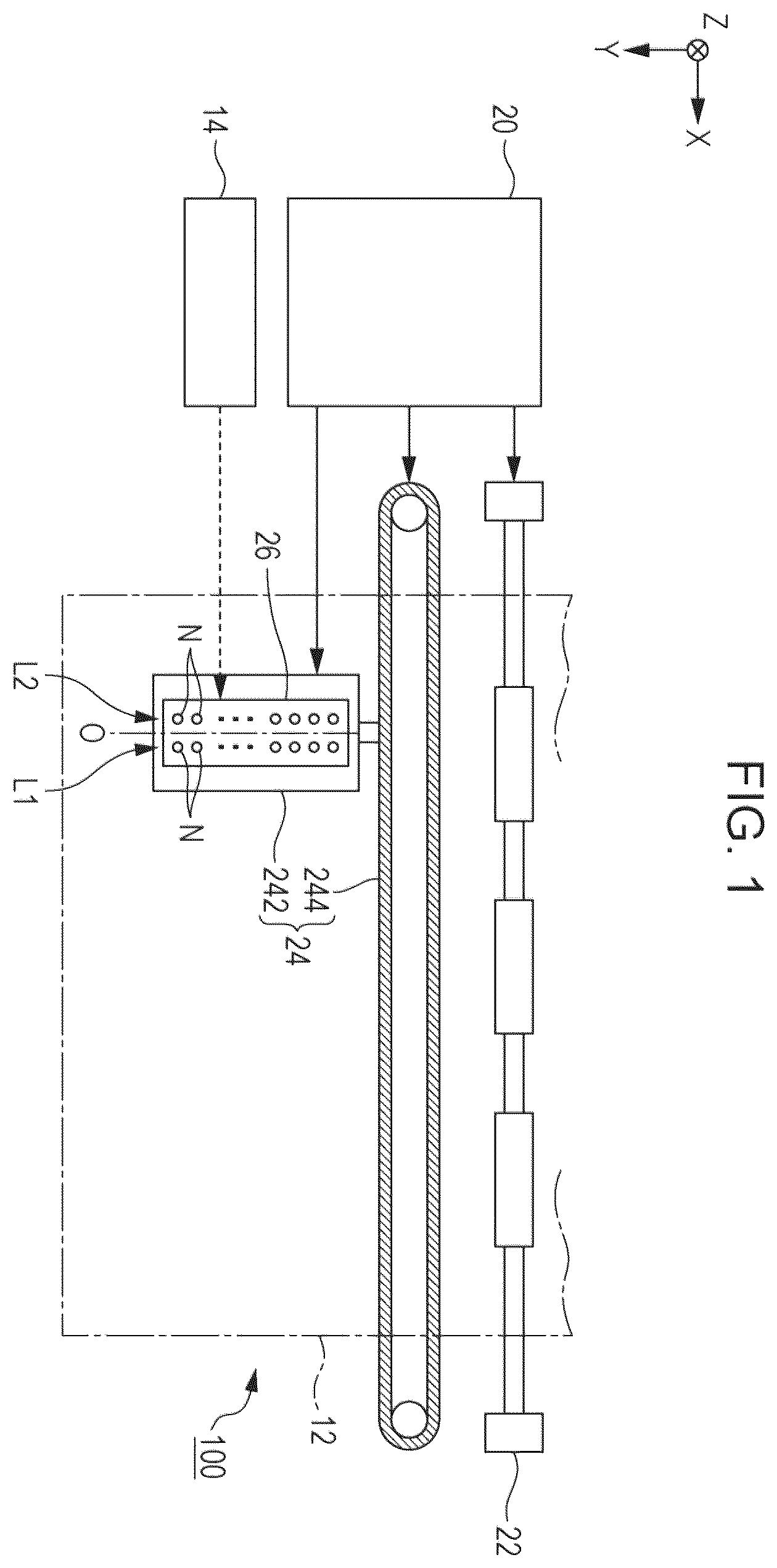
The ink jet device 100 of the present embodiment is a printing device for an ink jet method of discharging an aqueous ink jet ink composition onto a fabric 12 as a recording medium. An ink container 14 that stores an aqueous ink jet ink composition is installed in the ink jet device 100 . For example, a cartridge that is attachable or detachable from the ink jet device 100 , a bag-shaped ink pack formed from a flexible film, or an ink tank that can be refilled with an aqueous ink jet ink composition is utilized as the ink container 14 . The ink jet device 100 may include, for example, a plurality of ink containers 14 corresponding to a plurality of aqueous ink jet ink compositions.
The ink jet device 100 includes a control unit 20 , a transport mechanism 22 , a moving mechanism 24 , and an ink jet head 26 . The control unit 20 includes, for example, a processing circuit such as a Central Processing Unit (CPU) or a Field Programmable Gate Array (FPGA); and a storage circuit such as a semiconductor memory, and controls each of the elements of the ink jet device 100 in an integrated manner. The transport mechanism 22 transports the fabric 12 in the Y-direction under the control by the control unit 20 .
The moving mechanism 24 reciprocates the ink jet head 26 in the X-direction under the control by the control unit 20 . The X-direction is a direction intersecting the Y-direction in which the fabric 12 is transported, and the X-direction is typically a direction that is orthogonal to the Y-direction. The moving mechanism 24 includes a box-shaped transport body 242 that houses the ink jet head 26 , and a transport belt 244 to which the transport body 242 is fixed. A configuration in which a plurality of ink jet heads 26 are mounted on the transport body 242 , or a configuration in which the ink container 14 is mounted, together with the ink jet head 26 , on the transport body 242 may be used.
The ink jet head 26 discharges the aqueous ink jet ink composition supplied from the ink container 14 through a plurality of nozzles N onto a fabric 12 under the control of the control unit 20 . In parallel with the transport of the fabric 12 by the transport mechanism 22 and with the repetitive reciprocation of the transport body 242 , each ink jet head 26 discharges the aqueous ink jet ink composition onto the fabric 12 so that a desired image is formed on the surface of the fabric 12 . A direction perpendicular to the X-Y plane will be described as Z-direction in the following description. The direction of discharge of the aqueous ink jet ink composition by each ink jet head 26 , typically the vertical direction, corresponds to the Z-direction.
The nozzles N of the ink jet head 26 are arranged in the Y-direction. The nozzles N are divided into a first row L 1 and a second row L 2 , which are disposed in parallel with each other at an interval in the X-direction. Each of the first row L 1 and the second row L 2 is a set of a plurality of nozzles N linearly arranged in the Y-direction. It is also possible to make the respective positions of the nozzles N in the Y-direction different between the first row L 1 and the second row L 2 and to adopt, for example, a zigzag arrangement or a staggered arrangement, and in the following description, a case will be described in which the respective positions of the nozzles N in the Y-direction match between the first row L 1 and the second row L 2 . A plane that passes through the central axis parallel to the Y-direction and is parallel to the Z-direction in the ink jet head 26 , that is, the Y-Z plane, is referred to as “center plane O” in the following description.
As shown in , the ink jet head 26 has a structure in which the respective elements related to the nozzles N in the first row L 1 as a first nozzle and the respective elements related to the nozzles N in the second row L 2 as a second nozzle are disposed in plane symmetry, with the center plane O interposed therebetween. That is, the structure is substantially common between a first portion P 1 , which is a portion in the positive side in the X-direction, and a second portion P 2 , which is a portion in the negative side in the X-direction, with the center plane O interposed therebetween in the ink jet head 26 . The nozzles N in the first row L 1 are formed in the first portion P 1 , and the nozzles N in the second row L 2 are formed in the second portion P 2 . The center plane O corresponds to a boundary plane between the first portion P 1 and the second portion P 2 .
As shown in and , the ink jet head 26 includes a flow path forming section 30 . The flow path forming section 30 is a structure that forms flow paths for supplying an aqueous ink jet ink composition to the nozzles N. The flow path forming section 30 is configured such that a first flow path substrate 32 , which is a communicating plate, and a second flow path substrate 34 , which is a pressure chamber forming plate, are laminated. Each of the first flow path substrate 32 and the second flow path substrate 34 is a plate-shaped member elongated in the Y-direction. The second flow path substrate 34 is installed, for example, by utilizing an adhesive, on a surface Fa on the negative side in the Z-direction of the first flow path substrate 32 .
As shown in , on the surface Fa of the first flow path substrate 32 , a vibrator 42 , a plurality of piezoelectric elements 44 , a protective member 46 , and a housing section 48 are installed in addition to the second flow path substrate 34 . On the other hand, a nozzle plate 52 and a vibration absorber 54 are installed on the positive side in the Z-direction in the first flow path substrate 32 , that is, on a surface Fb at an opposite side from the surface Fa. Each of the elements of the ink jet head 26 is approximately a plate-shaped member elongated in the Y-direction as is the case of the first flow path substrate 32 and the second flow path substrate 34 , and is joined to each other by, for example, an adhesive. The direction in which the first flow path substrate 32 and the second flow path substrate 34 are laminated, or the direction in which the first flow path substrate 32 and the nozzle plate 52 are laminated, can be understood as the Z-direction.
The nozzle plate 52 is a plate-shaped member in which a plurality of nozzles N are formed, and the nozzle plate 52 is installed on the surface Fb of the first flow path substrate 32 by utilizing, for example, an adhesive. Each of the nozzles N is a circular-shaped through-hole, through which the aqueous ink jet ink composition is passed. In the nozzle plate 52 , a plurality of nozzles N constituting the first row L 1 and a plurality of nozzles N constituting the second row L 2 are formed. Specifically, the nozzles N of the first row L 1 are formed along the Y-direction in the nozzle plate 52 , in a region on the positive side in the X-direction as viewed from the center plane O, and the nozzles N of the second row L 2 are formed along the Y-direction in a region on the negative side in the X-direction. The nozzle plate 52 is a single plate-shaped member that extends continuously over the portion where a plurality of nozzles N of the first row L 1 are formed and the portion where a plurality of nozzles N of the second row L 2 are formed.
As shown in and , in the first flow path substrate 32 , a space Ra, a plurality of supply paths 61 , and a plurality of communicating paths 63 are formed in each of the first portion P 1 and the second portion P 2 . The space Ra is an opening formed into an elongated shape along the Y-direction in plan view, that is, as viewed from the Z-direction, and the supply paths 61 and the communicating paths 63 are through-holes formed in every nozzle N. The communicating paths 63 are arranged in the Y-direction in plan view, and the supply paths 61 are arranged in the Y-direction between the arrangement of the communicating paths 63 and the space Ra. The supply paths 61 communicate in common with the space Ra. Furthermore, any one communicating path 63 overlaps with the nozzle N corresponding to that communicating path 63 in plan view. Specifically, any one communicating path 63 of the first portion P 1 communicates with one nozzle N corresponding to that communicating path 63 in the first row L 1 . Similarly, any one communicating path 63 of the second portion P 2 communicates with one nozzle N corresponding to that communicating path 63 in the second row L 2 .
As shown in and , the second flow path substrate 34 is a plate-shaped member in which a plurality of pressure chambers C are formed for each of the first portion P 1 and the second portion P 2 . The pressure chambers C are arranged in the Y-direction. Each of the pressure chambers C is a space having an elongated shape along the X-direction in plan view, which is formed for every nozzle N.
As shown in , a vibrator 42 is installed on a surface at an opposite side of the second flow path substrate 34 from the first flow path substrate 32 . The vibrator 42 is a plate-shaped member that can vibrate elastically, that is, a vibrating plate. The second flow path substrate 34 and the vibrator 42 can also be formed integrally by selectively removing, in a plate-shaped member having a predetermined plate thickness, a portion in the plate thickness direction corresponding to the pressure chamber C.
As shown in , the surface Fa of the first flow path substrate 32 and the vibrator 42 face each other at a distance on the inner side of each pressure chamber C. The pressure chamber C is a space located between the surface Fa of the first flow path substrate 32 and the vibrator 42 and causes a pressure change in the aqueous ink jet ink composition filled in the space. Each pressure chamber C is, for example, a space whose longitudinal direction lies in the X-direction, and each pressure chamber C is individually formed for every nozzle N. A plurality of pressure chambers C are arranged in the Y-direction for each of the first row L 1 and the second row L 2 . As shown in and , the end portion of any one pressure chamber C on the center plane O side overlaps the communicating path 63 in plan view, and the end portion at an opposite side opposite from the center plane O overlaps the supply path 61 in plan view. Therefore, in each of the first portion P 1 and the second portion P 2 , the pressure chamber C communicates with the nozzle N via the communicating path 63 and also communicates with the space Ra via the supply path 61 .
As shown in , on a surface of the vibrator 42 at an opposite side from the pressure chamber C, a plurality of piezoelectric elements 44 corresponding to different nozzles N are installed for each of the first portion P 1 and the second portion P 2 . The piezoelectric element 44 is a passive element that is deformed by a supply of a driving signal. The piezoelectric elements 44 are arranged in the Y-direction so as to correspond to the respective pressure chambers C. As shown in , any one piezoelectric element 44 is a laminated body in which a piezoelectric layer 443 is interposed between a first electrode 441 and a second electrode 442 , which face each other. One of the first electrode 441 and the second electrode 442 can be used as an electrode extending continuously over a plurality of piezoelectric elements 44 , that is, a common electrode. A portion where the first electrode 441 , the second electrode 442 , and the piezoelectric layer 443 overlap in plan view, functions as the piezoelectric element 44 . A portion deformed by a supply of a driving signal, that is, the active portion that causes the vibrator 42 to vibrate, can also be demarcated as the piezoelectric element 44 . As such, the ink jet head 26 according to the present embodiment includes a first piezoelectric element and a second piezoelectric element. For example, the first piezoelectric element is a piezoelectric element 44 on one side in the X-direction as viewed from the center plane O, and the second piezoelectric element is a piezoelectric element 44 on the other side in the X-direction as viewed from the center plane O. When the vibrator 42 vibrates in conjunction with the deformation of the piezoelectric element 44 , as the pressure in the pressure chamber C fluctuates, the aqueous ink jet ink composition filled in the pressure chamber C is discharged by passing through the communicating path 63 and the nozzle N.
The protective member 46 is a plate-shaped member for protecting a plurality of piezoelectric elements 44 and is installed on the surface of the vibrator 42 . The piezoelectric elements 44 are housed in a recess formed on the surface of the protective member 46 on the vibrator 42 side.
An end portion of the wiring board 28 is joined to the surface at an opposite side of the vibrator 42 from the flow path forming section 30 . The wiring board 28 is a flexible mounting component on which is formed a plurality of wirings not shown in the diagram, the wirings electrically coupling the control unit 20 and the ink jet head 26 . In the wiring board 28 , an end portion extending toward the outside through an opening formed in the protective member 46 and an opening formed in the housing section 48 is coupled to the control unit 20 . For example, a flexible wiring board 28 such as a Flexible Printed Circuit (FPC) or a Flexible Flat Cable (FFC) is suitably employed.
The housing section 48 is a case for storing the aqueous ink jet ink composition that is supplied to a plurality of pressure chambers C. The surface of the housing section 48 on the positive side in the Z-direction is joined to the surface Fa of the first flow path substrate 32 with, for example, an adhesive.
As shown in , a space Rb is formed in the housing section 48 for each of the first portion P 1 and the second portion P 2 . The space Rb of the housing section 48 and the space Ra of the first flow path substrate 32 communicate with each other. The space composed of the space Ra and the space Rb functions as an ink storage chamber R that stores the aqueous ink jet ink composition supplied to a plurality of pressure chambers C. The ink storage chamber R is a common ink chamber shared by a plurality of nozzles N. An ink storage chamber R is formed in each of the first portion P 1 and the second portion P 2 . The ink storage chamber R of the first portion P 1 is located on the positive side in the X-direction as viewed from the center plane O, and the ink storage chamber R of the second portion P 2 is located on the negative side in the X-direction as viewed from the center plane O. An inlet port 482 for introducing the aqueous ink jet ink composition supplied from the ink container 14 into the ink storage chamber R is formed on the surface of the housing section 48 at an opposite side from the first flow path substrate 32 .
As shown in , a vibration absorber 54 is installed on the surface Fb of the first flow path substrate 32 for each of the first portion P 1 and the second portion P 2 . The vibration absorber 54 is a flexible film that absorbs pressure fluctuations in the aqueous ink jet ink composition inside the ink storage chamber R. As shown in , the vibration absorber 54 is installed on the surface Fb of the first flow path substrate 32 so as to block the space Ra of the first flow path substrate 32 and a plurality of supply paths 61 , and constitutes the wall surface of the ink storage chamber R.
As shown in , a circulation ink chamber 65 is formed on the surface Fb of the first flow path substrate 32 , the surface Fb facing the nozzle plate 52 . The circulation ink chamber 65 is a bottomed hole having an elongated shape and extending in the Y-direction in plan view. The opening of the circulation ink chamber 65 is closed by the nozzle plate 52 joined to the surface Fb of the first flow path substrate 32 .
As shown in , the circulation ink chamber 65 extends continuously over a plurality of nozzles N along the first row L 1 and the second row L 2 . Specifically, the circulation ink chamber 65 is formed between the arrangement of the nozzles N in the first row L 1 and the arrangement of the nozzles N in the second row L 2 . Therefore, as shown in , the circulation ink chamber 65 is located between the communicating path 63 of the first portion P 1 and the communicating path 63 of the second portion P 2 . As described above, the flow path forming section 30 of the present embodiment is a structure in which are formed a first communicating path including the first pressure chamber, which is the pressure chamber C in the first portion P 1 , and the communicating path 63 ; a second communicating path including the second pressure chamber, which is the pressure chamber C in the second portion P 2 , and the communicating path 63 ; and the circulation ink chamber 65 located between the communicating path 63 of the first portion P 1 and the communicating path 63 of the second portion P 2 . As shown in , the flow path forming section 30 of the first embodiment includes a partition wall section 69 that partitions the circulation ink chamber 65 from each of the communicating paths 63 .
As described above, a plurality of the pressure chambers C and a plurality of the piezoelectric elements 44 are arranged in the Y-direction in each of the first portion P 1 and the second portion P 2 . Therefore, it can be paraphrased that the circulation ink chamber 65 extends in the Y-direction so as to be continuous over a plurality of the pressure chambers C or a plurality of the piezoelectric elements 44 in each of the first portion P 1 and the second portion P 2 . Furthermore, as shown in and , it is also possibly configured that the circulation ink chamber 65 and the ink storage chamber R extend in the Y-direction at a distance from each other, and a pressure chamber C, a communicating path 63 , and a nozzle N are located within the distance.
As shown in , one nozzle N includes a first segment n 1 and a second segment n 2 . The first segment n 1 and the second segment n 2 are circular spaces that are coaxially formed and communicate with each other. The second segment n 2 is located on the flow path forming section 30 side as viewed from the first segment n 1 . The inner diameter d 2 of the second segment n 2 is larger than the inner diameter d 1 of the first segment n 1 . According to the configuration in which each nozzle N is formed in a stepwise manner as described above, there is an advantage that the flow path resistance of each nozzle N can be easily set to have desired characteristics. Furthermore, as shown in , the central axis Qa of each nozzle N is located on the opposite side of the circulation ink chamber 65 when viewed from the central axis Qb of the communicating path 63 .
On the surface of the nozzle plate 52 facing the flow path forming section 30 , a plurality of circulation paths 72 are formed for each of the first portion P 1 and the second portion P 2 . A plurality of the circulation paths 72 of the first portion P 1 , which constitutes the first circulation path, correspond on a one-to-one basis to a plurality of the nozzles N of the first row L 1 . Furthermore, a plurality of the circulation paths 72 of the second portion P 2 , which constitute the second circulation path, correspond on a one-to-one basis to a plurality of the nozzles N of the second row L 2 .
Each of the circulation paths 72 is a bottomed hole having an elongated shape extending in the X-direction, and functions as a flow path for circulating the aqueous ink jet ink composition. The circulation paths 72 are formed at positions separated apart from the nozzles N, specifically, on the circulation ink chamber 65 side when viewed from the nozzles N corresponding to the circulation paths 72 .
As shown in , each circulation path 72 is formed linearly in the nozzle N at a flow path width Wa, which is equivalent to the inner diameter d 2 of the second segment n 2 . The flow path width Wa, which is the dimension of the circulation path 72 in the Y-direction, is smaller than a flow path width Wb, which is the dimension of the pressure chamber C in the Y-direction. Therefore, the flow path resistance of the circulation path 72 can be increased as compared with the configuration in which the flow path width Wa of the circulation path 72 is larger than the flow path width Wb of the pressure chamber C. On the other hand, the depth Da of the circulation path 72 with respect to the surface of the nozzle plate 52 is constant over the entire length. Specifically, each circulation path 72 is formed to have a depth equivalent to that of the second segment n 2 of the nozzle N. According to the above-described configuration, there is an advantage that the circulation path 72 and the second segment n 2 can be easily formed as compared with the configuration in which the circulation path 72 and the second segment n 2 are formed at different depths. The “depth” of the flow path means the depth of the flow path in the Z-direction.
Any one circulation path 72 in the first portion P 1 is located on the circulation ink chamber 65 side of the first row L 1 as viewed from the nozzle N corresponding to that circulation path 72 . Furthermore, any one circulation path 72 in the second portion P 2 is located on the circulation ink chamber 65 side of the second row L 2 as viewed from the nozzle N corresponding to that circulation path 72 . The end portion of each circulation path 72 at an opposite side from the center plane O, that is, on the communicating path 63 side, overlaps one communicating path 63 corresponding to that circulation path 72 in plan view. That is, the circulation path 72 communicates with the communicating path 63 . On the other hand, the end portion of each circulation path 72 on the center plane O side, that is, on the circulation ink chamber 65 side, overlaps the circulation ink chamber 65 in plan view. That is, the circulation path 72 communicates with the circulation ink chamber 65 . As described above, each of a plurality of the communicating paths 63 communicates with the circulation ink chamber 65 via the circulation path 72 . Therefore, as shown by the broken line arrow in , the aqueous ink jet ink composition in each communicating path 63 is supplied to the circulation ink chamber 65 via the circulation path 72 . That is, a plurality of communicating paths 63 corresponding to the first row L 1 and a plurality of communicating paths 63 corresponding to the second row L 2 communicate in common with one circulation ink chamber 65 .
shows the flow path length La of the portion of any one circulation path 72 overlapping the circulation ink chamber 65 , the flow path length Lb of the portion of the circulation path 72 overlapping the communicating path 63 , and the flow path length Lc of the portion of the circulation path 72 overlapping the partition wall section 69 of the flow path forming section 30 . The flow path length Lc corresponds to the thickness of the partition wall section 69 . The partition wall section 69 functions as a throttle portion of the circulation path 72 . Therefore, as the flow path length Lc corresponding to the thickness of the partition wall section 69 is longer, the flow path resistance of the circulation path 72 increases. In the present embodiment, established is the relationship that the flow path length La is longer than the flow path length Lb, and that the flow path length La is longer than the flow path length Lc. Furthermore, in the present embodiment, the relationship that the flow path length Lb is longer than the flow path length Lc, is established. According to the above-described configuration, there is an advantage that as compared with the configuration in which the flow path length La and the flow path length Lb are shorter than the flow path length Lc, the aqueous ink jet ink composition can easily flow from the communicating path 63 to the circulation ink chamber 65 via the circulation path 72 .
As described above, in the present embodiment, the pressure chamber C indirectly communicates with the circulation ink chamber 65 via the communicating path 63 and the circulation path 72 . That is, the pressure chamber C and the circulation ink chamber 65 do not directly communicate with each other. In the above-described configuration, when the pressure in the pressure chamber C fluctuates due to the operation of the piezoelectric element 44 , a portion of the aqueous ink jet ink composition flowing in the communicating path 63 is discharged through the nozzle N to the outside, while a portion of the remaining ink composition for aqueous ink jet ink composition flows from the communicating path 63 into the circulation ink chamber 65 via the circulation path 72 . In the present embodiment, inertance between the communicating path 63 , the nozzle N, and the circulation path 72 is selected such that with regard to the aqueous ink jet ink composition flowing through the communicating path 63 by one-time driving of the piezoelectric element 44 , the discharge amount, which is the amount of the aqueous ink jet ink composition discharged through the nozzle N, is larger than the circulation amount, which is the amount of the aqueous ink jet ink composition flowing into the circulation ink chamber 65 through the circulation path 72 in the aqueous ink jet ink composition flowing through the communicating path 63 . Assuming that all the piezoelectric elements 44 are driven all at once, it can be said that the sum of the circulating amounts flowing from a plurality of communicating paths 63 into the circulation ink chamber 65 is larger than the sum of the discharge amounts passed through a plurality of nozzles N.
Specifically, the flow path resistance of each of the communicating path 63 , the nozzle N, and the circulation path 72 is determined such that, for example, the ratio of the circulation amount in the aqueous ink jet ink composition flowing through the communicating path 63 is 70% or more, that is, the ratio of the discharge amount is 30% or less. According to the above-described configuration, it is possible to effectively circulate the aqueous ink jet ink composition in the vicinity of the nozzle N to the circulation ink chamber 65 while securing the discharge amount of the aqueous ink jet ink composition. Generally, there is a tendency that when the flow path resistance of the circulation path 72 is larger, the discharge amount increases while the circulation amount decreases, and when the flow path resistance of the circulation path 72 is smaller, the discharge amount decreases while the circulation amount increases.
As shown in , the ink jet device 100 includes a circulation mechanism 75 . The circulation mechanism 75 is a mechanism for supplying, that is, circulating, the aqueous ink jet ink composition in the circulation ink chamber 65 to the ink storage chamber R. Although not shown in the diagram, the circulation mechanism 75 includes, for example, a suction mechanism such as a pump, which suctions the aqueous ink jet ink composition from the circulation ink chamber 65 , a filter mechanism that collects air bubbles and foreign materials mixed in the aqueous ink jet ink composition, and a heating mechanism that reduces thickening, caused by heating, of the aqueous ink jet ink composition. The aqueous ink jet ink composition, in which air bubbles and foreign materials have been removed and thickening has been reduced by the circulation mechanism 75 , is supplied from the circulation mechanism 75 to the ink storage chamber R through the inlet port 482 . As described above, the aqueous ink jet ink composition circulates in the course of ink storage chamber R→supply path 61 →pressure chamber C→communicating path 63 →circulation path 72 →circulation ink chamber 65 →circulation mechanism 75 →ink storage chamber R.
As shown in , the circulation mechanism 75 suctions the aqueous ink jet ink composition from both sides of the circulation ink chamber 65 in the Y-direction. That is, the circulation mechanism 75 suctions the aqueous ink jet ink composition from the vicinity of the end portion of the circulation ink chamber 65 on the negative side in the Y-direction and from the vicinity of the end portion of the circulation ink chamber 65 on the positive side in the Y-direction. In the configuration in which the aqueous ink jet ink composition is suctioned through only one end portion of the circulation ink chamber 65 in the Y-direction, there occurs a difference in the pressure of the aqueous ink jet ink composition between the two end portions of the circulation ink chamber 65 , and due to the pressure difference in the circulation ink chamber 65 , the pressure of the aqueous ink jet ink composition in the communicating path 63 may vary depending on the position in the Y-direction. Therefore, there is a possibility that the characteristics of discharge of the aqueous ink jet ink composition through each nozzle N, for example, the discharge amount and the discharge speed, may vary depending on the position in the Y-direction. In contrast to the above-described configuration, in the present embodiment, since the aqueous ink jet ink composition is suctioned through both sides of the circulation ink chamber 65 , the pressure difference inside the circulation ink chamber 65 is reduced. Therefore, it is possible to approximate the discharge characteristics of the aqueous ink jet ink composition with high accuracy over a plurality of nozzles N arranged in the Y-direction. However, when the pressure difference in the Y-direction in the circulation ink chamber 65 does not pose a particular problem, a configuration in which the aqueous ink jet ink composition is suctioned through one end portion of the circulation ink chamber 65 may be adopted.
As described above, the ink jet device 100 of the present embodiment includes a nozzle plate 52 provided with a first nozzle and a second nozzle; a first pressure chamber and a second pressure chamber, to which the aqueous ink jet ink composition is supplied; a first communicating path that allows the first nozzle and the first pressure chamber to communicate with each other; a second communicating path that allows the second nozzle and the second pressure chamber to communicate with each other; a flow path forming section 30 provided with a circulation ink chamber 65 that is located between the first communicating path and the second communicating path; and an ink jet head 26 having a pressure generating section that generates a pressure change in each of the first pressure chamber and the second pressure chamber. The nozzle plate 52 is provided with a first circulation path that allows the first communicating path and the circulation ink chamber 65 to communicate with each other, and a second circulation path that allows the second communicating path and the circulation ink chamber to communicate with each other.
4-2. Second Embodiment
is a perspective view of an ink jet device of a second embodiment. is a perspective view of a main tank included in the ink jet device shown in . is a perspective view of the external appearance of an ink jet head included in the ink jet device shown in . is a sectional view of the ink jet head shown in in a direction orthogonal to the direction of nozzle arrangement. is a sectional view of the ink jet head shown in in a direction parallel to the direction of nozzle arrangement. is a plan view of the nozzle plate of the ink jet head shown in . A to F are plan views of each member constituting the flow path member of the ink jet head shown in . A and B are plan views of each member constituting the common ink chamber member of the ink jet head shown in . is a block diagram showing an example of an ink circulation system in the ink jet device of the present embodiment. is a sectional view taken along the line XVI-XVI in . is a sectional view taken along the line XVII-XVII in .
A mechanical section B 420 is provided in the outer packaging B 401 of the ink jet device B 400 . Each of the ink accommodating sections B 411 of a main tank B 410 k , a main tank B 410 c , a main tank B 410 m , and a main tank B 410 y , which are the main tanks B 410 for the colors of black, cyan, magenta, and yellow, respectively, is formed from, for example, a packaging member such as an aluminum laminate film. The ink accommodating sections B 411 are housed in, for example, a plastic accommodating container case B 414 . As a result, the main tanks B 410 are used as ink cartridges for the respective colors.
On the other hand, a cartridge holder B 404 is provided on the inner side of the opening when a cover B 401 c of the main body of the device is opened. The main tanks B 410 are attachably and detachably fitted to the cartridge holder B 404 . As a result, each of ink discharge ports B 413 of the main tanks B 410 and an ink jet head B 424 for each color communicate with each other via a supply tube B 436 for each color, and an aqueous ink jet ink composition can be discharged from the ink jet head B 424 toward a fabric as a recording medium.
The ink jet head B 424 has a nozzle plate B 1 , a flow path plate B 2 , and a vibrating plate member B 3 as a wall surface member laminated and joined therein. Further, the ink jet head B 424 includes a piezoelectric actuator B 11 that displaces the vibrating plate member B 3 , a common ink chamber member B 20 , and a cover B 29 . The nozzle plate B 1 has a plurality of nozzles B 4 that discharge an aqueous ink jet ink composition.
The flow path plate B 2 forms individual ink chambers B 6 communicating with the nozzle B 4 , a fluid resistance section B 7 communicating with the individual ink chambers B 6 , and an ink inlet section B 8 communicating with the fluid resistance section B 7 . Furthermore, the flow path plate B 2 is formed by laminating and joining a plurality of plate-shaped members B 41 , B 42 , B 43 , B 44 , and B 45 from the nozzle plate B 1 side, and these plate-shaped members B 41 , B 42 , B 43 , B 44 , and B 45 and the vibrating plate member B 3 are laminated and joined to constitute a flow path member B 40 .
The vibrating plate member B 3 has a filter section B 9 as an opening that communicates with the ink inlet section B 8 and the common ink chamber B 10 formed by the common ink chamber member B 20 .
The vibrating plate member B 3 is a wall surface member that forms the wall surface of the individual ink chambers B 6 of the flow path plate B 2 . This vibrating plate member B 3 has a two-layer structure and is formed of a first layer that forms a thin portion and a second layer that forms a thick portion, from the flow path plate B 2 side, and a deformable vibration region B 30 is formed in the portion corresponding to the individual ink chamber B 6 at the first layer.
Here, as shown in , a plurality of nozzles B 4 are disposed in a zigzag pattern in the nozzle plate B 1 .
As shown in A , the plate-shaped member B 41 constituting the flow path plate B 2 has formed therein a through-groove section B 6 a constituting the individual ink chamber B 6 , and through-groove sections B 51 a and B 52 a constituting the fluid resistance section B 51 and the circulation path B 52 .
As shown in B , the same plate-shaped member B 42 has formed therein a through-groove section B 6 b constituting the individual ink chamber B 6 , and a through-groove section B 52 b constituting the circulation path B 52 .
As shown in C , the same plate-shaped member B 43 has formed in a through-groove section B 6 c constituting the individual ink chamber B 6 , and a through-groove section B 53 a in which the direction of the nozzle arrangement constituting the circulation path B 53 is the longitudinal direction.
As shown in D , the same plate-shaped member B 44 has formed therein a through-groove section B 6 d constituting the individual ink chamber B 6 , a through-groove section B 7 a forming the fluid resistance section B 7 , a through-groove section B 8 a constituting the ink inlet section B 8 , and a through-groove section B 53 b in which the direction of the nozzle arrangement constituting the circulation path B 53 is the longitudinal direction.
As shown in E , the same plate-shaped member B 45 has formed therein a through-groove section B 6 e constituting the individual ink chamber B 6 ; a through-groove section B 8 b which forms an ink chamber in the downstream of the filter, and in which the direction of the nozzle arrangement constituting the ink inlet section B 8 is the longitudinal direction; and a through-groove section B 53 c in which the direction of the nozzle arrangement constituting the circulation path B 53 is the longitudinal direction.
As shown in F , the vibrating plate member B 3 has formed therein a vibration region B 30 , the filter section B 9 , and a through-groove section B 53 d in which the direction of the nozzle arrangement constituting the circulation path B 53 is the longitudinal direction.
As such, a complicated flow path can be formed with a simple configuration by configuring the flow path member by laminating and joining a plurality of plate-shaped members.
Based on the above-described configuration, the flow path member B 40 composed of the flow path plate B 2 and the vibrating plate member B 3 has formed therein the fluid resistance section B 51 along the planar direction of the flow path plate B 2 that communicates with the respective individual ink chambers B 6 ; and the circulation path B 52 as well as the circulation path B 53 that is in the thickness direction of the flow path member B 40 communicating with the circulation path B 52 . The circulation path B 53 communicates with the circulation common ink chamber B 50 , which will be described later.
On the other hand, the common ink chamber member B 20 has a common ink chamber B 10 and a circulation common ink chamber B 50 formed therein.
As shown in A , the first common ink chamber member B 21 constituting the common ink chamber member B 20 has formed therein a through-hole B 25 a for a piezoelectric actuator, a through-groove section B 10 a that serves as a downstream common ink chamber B 10 A, and a groove section B 50 a that has a bottom and serves as a circulation common ink chamber B 50 .
As shown in B , the same second common ink chamber member B 22 is provided with a through-hole B 25 b for a piezoelectric actuator, and a groove section B 10 b serving as an upstream common ink chamber B 10 B.
Furthermore, the second common ink chamber member B 22 is provided with a through-hole B 71 a that serves as one end portion of the common ink chamber B 10 in the direction of the nozzle arrangement and a supply port section communicating with the supply port B 71 .
Similarly, the first common ink chamber member B 21 and the second common ink chamber member B 22 are provided with through-holes B 81 a and B 81 b , which communicate with the other end of the circulation common ink chamber B 50 in the direction of the nozzle arrangement and the circulation port B 81 .
In addition, shows a groove section with a bottom that has been subjected to surface coating. The same applies to the following diagrams.
As such, the common ink chamber member B 20 is composed of a first common ink chamber member B 21 and a second common ink chamber member B 22 , and the first common ink chamber member B 21 is joined to the vibrating plate member B 3 side of the flow path member B 40 while the second common ink chamber member B 22 is laminated and joined to the first common ink chamber member B 21 .
Here, the first common ink chamber member B 21 forms a downstream common ink chamber B 10 A, which is a portion of the common ink chamber B 10 communicating with the ink inlet section B 8 , and a circulation common ink chamber B 50 communicating with the circulation path B 53 . Furthermore, the second common ink chamber member B 22 forms the upstream common ink chamber B 10 B, which is the rest of the common ink chamber B 10 .
At this time, the downstream common ink chamber B 10 A, which is a portion of the common ink chamber B 10 , and the circulation common ink chamber B 50 are disposed in parallel with the direction orthogonally intersecting the direction of the nozzle arrangement, and the circulation common ink chamber B 50 is disposed at a position projected into the common ink chamber B 10 .
As a result, the dimensions of the circulation common ink chamber B 50 are not subjected to limitations according to the dimensions required for a flow path including the individual ink chambers B 6 , the fluid resistance section B 7 , and the ink inlet section B 8 , which are formed by the flow path member B 40 .
Then, since the circulation common ink chamber B 50 and a portion of the common ink chamber B 10 are disposed in parallel, and the circulation common ink chamber B 50 is disposed at a position projected into the common ink chamber B 10 , the width of the head in a direction orthogonally intersecting the direction of the nozzle arrangement can be suppressed, and an increase in the size of the head can be suppressed. The common ink chamber member B 20 forms the common ink chamber B 10 and the circulation common ink chamber B 50 , to which an aqueous ink jet ink composition is supplied from a head tank or an ink cartridge.
On the other hand, disposed on the opposite side of the vibrating plate member B 3 from the individual ink chambers B 6 is a piezoelectric actuator B 11 that includes an electromechanical conversion element as a driving unit that deforms the vibration region B 30 of the vibrating plate member B 3 .
As shown in , this piezoelectric actuator B 11 has a piezoelectric member B 12 joined onto a base member B 13 , and the piezoelectric member B 12 is grooved by half-cut dicing to form a required number of columnar piezoelectric elements B 12 A and B 12 B are formed, for one piezoelectric member B 12 , in a comb teeth shape at a predetermined interval.
Here, the piezoelectric element B 12 A of the piezoelectric member B 12 is used as a piezoelectric element to be driven by applying a drive waveform, and the piezoelectric element B 12 B is used as a mere prop without applying a drive waveform; however, all the piezoelectric elements B 12 A and B 12 B can also be used as piezoelectric elements to be driven.
Then, the piezoelectric element B 12 A is joined to a convex portion B 30 a , which is an island-shaped thick portion formed in the vibration region B 30 of the vibrating plate member B 3 . Furthermore, the piezoelectric element B 12 B is joined to a convex portion B 30 b , which is a thick portion of the vibrating plate member B 3 .
This piezoelectric member B 12 is formed by alternately laminating piezoelectric layers and internal electrodes, the internal electrodes are respectively drawn out to the end faces to provide external electrodes, and the flexible wiring member B 15 is coupled to the external electrodes.
In an ink jet head B 424 as a circulation type discharge head configured as such, for example, the piezoelectric element B 12 A contracts as the voltage applied to the piezoelectric element B 12 A is lowered from the reference potential, and the aqueous ink jet ink composition flows into the individual ink chamber B 6 as the vibration region B 30 of the vibrating plate member B 3 is lowered to cause the volume of the individual ink chamber B 6 expands.
Thereafter, when the voltage applied to the piezoelectric element B 12 A is increased to extend the piezoelectric element B 12 A in the direction of lamination, and the vibration region B 30 of the vibrating plate member B 3 is deformed in a direction facing toward the nozzle B 4 to cause the volume of the individual ink chamber B 6 to contract, the aqueous ink jet ink composition in the individual ink chamber B 6 is pressurized, and the aqueous ink jet ink composition is discharged through the nozzle B 4 .
Then, by returning the voltage applied to the piezoelectric element B 12 A to the reference potential, the vibration region B 30 of the vibrating plate member B 3 is restored to the initial position, the individual ink chambers B 6 expand to generate negative pressure, and accordingly, at this time, the aqueous ink jet ink composition is filled from the common ink chamber B 10 into the individual ink chambers B 6 . Thus, after the vibration of the meniscus surface at the nozzle B 4 is attenuated and stabilized, the operation for the next discharge is started.
The method of driving this head is not limited to the above-described example, and pull-strike or push-strike may be performed depending on the drive waveform. Furthermore, the above-described embodiment has been described by using a laminated type piezoelectric element has been described as the pressure generating unit that applies pressure fluctuation to the individual ink chamber B 6 ; however, the present disclosure is not limited to this, and a thin-film piezoelectric element can also be used. Moreover, a system in which a heat-generating resistor is disposed in the individual ink chamber B 6 so as to generate air bubbles by the heat generated by the heat-generating resistor and to cause pressure fluctuation, or a system in which pressure fluctuation is caused by using electrostatic force, can be used.
Next, an example of an ink circulation system using an ink jet head as a circulation type discharge head will be described with reference to .
As shown in , the ink circulation system is composed of a main tank B 410 , an ink jet head B 424 , a supply tank B 417 , a circulation tank B 415 , a compressor B 422 , a vacuum pump B 421 , a first liquid feeding pump B 416 , a second liquid feeding pump B 412 , a regulator B 419 , a supply-side pressure sensor B 418 , and a circulation side pressure sensor B 423 . The supply-side pressure sensor B 418 is disposed between the supply tank B 417 and the ink jet head B 424 and is coupled to a supply flow path side that is led to the supply port B 71 of the ink jet head B 424 . The circulation-side pressure sensor B 423 is disposed between the ink jet head B 424 and the circulation tank B 415 and is coupled to the circulation path side that is led to the circulation port B 81 of the ink jet head B 424 .
One of the circulation tanks B 415 is coupled to the supply tank B 417 via the first liquid feeding pump B 416 , and the other one of the circulation tanks B 415 is coupled to the main tank B 410 via the second liquid feeding pump B 412 . As a result, the aqueous ink jet ink composition flows from the supply tank B 417 through the supply port B 71 into the ink jet head B 424 , is discharged through the circulation port B 81 , and is discharged to the circulation tank B 415 , the aqueous ink jet ink composition is further transported from the circulation tank B 415 to the supply tank B 417 by the first liquid feeding pump B 416 , and thereby the aqueous ink jet ink composition is circulated.
Furthermore, the compressor B 422 is linked to the supply tank B 417 and is controlled such that a predetermined positive pressure is detected by the supply side pressure sensor B 418 . On the other hand, the vacuum pump B 421 is linked to the circulation tank B 415 and is controlled such that a predetermined negative pressure is detected by the circulation side pressure sensor B 423 . As a result, the negative pressure of the meniscus can be kept constant while circulating the aqueous ink jet ink composition through the ink jet head B 424 .
Furthermore, when liquid droplets are discharged through the nozzle B 4 of the ink jet head B 424 , since the amount of the aqueous ink jet ink composition in the supply tank B 417 and the circulation tank B 415 decreases, it is preferable to replenish the aqueous ink jet ink composition from the main tank B 410 to the circulation tank by appropriately using the second liquid feeding pump B 412 . The timing of replenishing the aqueous ink jet ink composition from the main tank B 410 to the circulation tank B 415 can be controlled by the detection results of the liquid level sensor or the like provided in the circulation tank B 415 , such that when the liquid level height of the aqueous ink jet ink composition in the circulation tank B 415 drops below a predetermined height, the aqueous ink jet ink composition is replenished.
Next, the circulation of the aqueous ink jet ink composition in the ink jet head B 424 will be described. As shown in , a supply port B 71 communicating with the common ink chamber B 10 and a circulation port B 81 communicating with the circulation common ink chamber B 50 are formed at the end portion of the common ink chamber member B 20 . The supply port B 71 and the circulation port B 81 are led to the supply tank B 417 and the circulation tank B 415 , which store the aqueous ink jet ink composition, respectively, via a tube. Then, the aqueous ink jet ink composition stored in the supply tank B 417 is supplied to the individual ink chamber B 6 via the supply port B 71 , the common ink chamber B 10 , the ink inlet section B 8 , and the fluid resistance section B 7 .
In addition, while the aqueous ink jet ink composition in the individual ink chambers B 6 is discharged through the nozzle B 4 by driving the piezoelectric member B 12 , a portion or all of the aqueous ink jet ink composition staying in the individual ink chambers B 6 without being discharged is circulated to the circulation tank B 415 via the fluid resistance section B 51 , the circulation paths B 52 and B 53 , the circulation common ink chamber B 50 , and the circulation port B 81 .
The circulation of the aqueous ink jet ink composition can be carried out not only when the ink jet head B 424 is in operation but also when the operation is stopped. By circulating the aqueous ink jet ink composition when the operation is stopped, the aqueous ink jet ink composition in the individual ink chambers B 6 is constantly refreshed, and aggregation and sedimentation of the components included in the aqueous ink jet ink composition can be suppressed, which is preferable.
5. Dyed Product
A dyed product, which is a recorded material according to the present disclosure, is a product produced by using the above-mentioned aqueous ink jet ink composition of the present disclosure, and the dyed product can be produced by using the above-mentioned recording method.
Thus, suitable embodiments of the present disclosure have been described above; however, the present disclosure is not intended to be limited to these.
For example, the ink jet device to which the present disclosure is applied is not limited to the above-mentioned ones. More specifically, the ink jet device to which the present disclosure is applied may be, for example, an ink jet device that does not have an ink circulation system.
Furthermore, the above-described embodiments have been described mainly based on the case where the recording medium to which the aqueous ink jet ink composition of the present disclosure is applied by an ink jet method is a fabric; however, the recording medium to which the aqueous ink jet ink composition of the present disclosure is applied by an ink jet method may be any recording medium. For example, the recording medium to which the aqueous ink jet ink composition of the present disclosure is applied by an ink jet method may be paper such as plain paper; or an intermediate transfer medium such as a recording medium provided with an ink absorbing layer, which is referred to as special paper for ink jet or coated paper.
EXAMPLES
Next, specific examples of the present disclosure will be described.
6. Preparation of Aqueous Ink Jet Ink Composition
Example 1
First, a color material composed of a compound represented by Formula (2) above and a compound represented by Formula (3) above was prepared. This color material was prepared, by salt substitution, so as to include 14500 ppm of sodium ions and 400 ppm of potassium ions as counterions.
Next, this color material, triethylene glycol monobutyl ether, propylene glycol, 2-pyrrolidone, OLFINE PD002W (manufactured by Nissin Chemical Industry Co., Ltd.), Proxel XL-2 (manufactured by Lonza Group), and ultrapure water were mixed at a predetermined ratio to prepare an aqueous ink jet ink composition having the composition shown in Table 1.
Examples 2 to 11
First, aqueous ink jet ink compositions were prepared in the same manner as in Example 1 described above, except that the color materials under the conditions shown in Table 1 were used as the color material.
Comparative Examples 1 to 5
First, aqueous ink jet ink compositions were prepared in the same manner as in Example 1 described above, except that the color materials under the conditions shown in Table 1 were used as the color material.
Table 1 shows together the conditions for each of the aqueous ink jet ink compositions of the above-described Examples and Comparative Examples. In Table 1, triethylene glycol monobutyl ether is described “BTG”, propylene glycol as “PG”, 2-pyrrolidone as “2-Py”, OLFINE PD002W (manufactured by Nissin Chemical Industry Co., Ltd.) as “PD002W”, and Proxel XL-2 (manufactured by Lonza Group) as “XL-2”. Furthermore, in Table 1, when the content of sodium ions in the aqueous ink jet ink composition is denoted by XA [% by mass], and the content of the alkali metal ion other than sodium ions in the aqueous ink jet ink composition is denoted by XB [% by mass], the values of XA/XB are shown. In Table 1, the content of the compound represented by Formula (2) above in the aqueous ink jet ink composition is denoted by X2 [% by mass], and the content of the compound represented by Formula (3) above is denoted by X3 [% by mass]. Regarding the aqueous ink jet ink composition of each of the above-described Examples, the surface tension had a value in the range of from 23 mN/m to 40 mN/m in all cases. The surface tension was measured by a Wilhelmy method at 25° C. using a surface tension meter (manufactured by Kyowa Interface Science Co., Ltd., CBVP-7). Furthermore, the viscosity at 25° C. of the aqueous ink jet ink composition of each of the above-described Examples had a value in the range of from 3 mPa·s to 6 mPa·s in all cases. The viscosity of the aqueous ink jet ink composition was determined by measurement according to JIS Z8809 using a vibration type viscometer (VM-100, manufactured by Sekonic Corporation).
TABLE 1
Water-soluble
organic solvent Water PD002W XL-2
Color material represented by Formula (1) Content Content Content Content
Content X2 X3 Content of counterions [ppm] [% by mass] [% by [% by [% by
[% by mass] [%] [%] X2/X3 Na + K + Li + NH 4 + XA/XB BTG PG 2-Py mass] mass] mass]
Example 1 20.0 50.0 50.0 1.0 14500 400 — — 36 5.0 5.0 5.0 64.7 0.2 0.1
Example 2 20.0 50.0 50.0 1.0 15000 50 — — 300 5.0 5.0 5.0 64.7 0.2 0.1
Example 3 20.0 50.0 50.0 1.0 14500 — 400 — 36 5.0 5.0 5.0 64.7 0.2 0.1
Example 4 20.0 50.0 50.0 1.0 14500 200 200 — 36 5.0 5.0 5.0 64.7 0.2 0.1
Example 5 20.0 50.0 50.0 1.0 14500 15 — — 967 5.0 5.0 5.0 64.7 0.2 0.1
Example 6 20.0 50.0 50.0 1.0 14500 20 — — 725 5.0 5.0 5.0 64.7 0.2 0.1
Example 7 20.0 50.0 50.0 1.0 10000 5000 — — 2 5.0 5.0 5.0 64.7 0.2 0.1
Example 8 20.0 85.0 15.0 5.7 14500 400 — — 36 5.0 5.0 5.0 64.7 0.2 0.1
Example 9 20.0 65.0 35.0 1.9 14500 400 — — 36.25 5.0 5.0 5.0 64.7 0.2 0.1
Example 10 20.0 15.0 85.0 0.2 14500 400 — — 36 5.0 5.0 5.0 64.7 0.2 0.1
Example 11 20.0 35.0 65.0 0.5 14500 400 — — 36.25 5.0 5.0 5.0 64.7 0.2 0.1
Comparative 20.0 50.0 50.0 1.0 400 — — 14500 — 5.0 5.0 5.0 64.7 0.2 0.1
Example 1
Comparative 20.0 90.0 10.0 9.0 15000 — — — — 5.0 5.0 5.0 64.7 0.2 0.1
Example 2
Comparative 20.0 100.0 — — — — 500 15000 — 5.0 5.0 5.0 64.7 0.2 0.1
Example 3
Comparative 20.0 50.0 50.0 1.0 — 15000 — — — 5.0 5.0 5.0 64.7 0.2 0.1
Example 4
Comparative 20.0 50.0 50.0 1.0 — 7500 7500 — — 5.0 5.0 5.0 64.7 0.2 0.1
Example 5
7. Evaluation
The aqueous ink jet ink composition of each of the above-described Examples and Comparative Examples was evaluated as follows.
7-1. Discharge Stability
An ink jet device as shown in to was filled with an aqueous ink jet ink composition. After it was confirmed that all the nozzles of the evaluation machine were normally discharging the aqueous ink jet ink composition without any missing or warping, the aqueous ink jet ink composition was continuously discharged for 10 hours and was evaluated according to the following criteria. Grade C or higher was regarded as a favorable level.
•
• A: All nozzles discharge normally. • B: Missing or warping occurs in nozzles at a proportion of less than 10% with respect to the total number of nozzles. • C: Missing or warping occurs in nozzles at a proportion of 10% or more and less than 20% with respect to the total number of nozzles. • D: Missing or warping occurs in nozzles at a proportion of 20% or more and less than 40% with respect to the total number of nozzles. • E: Missing or warping occurs in nozzles at a proportion of 40% or more with respect to the total number of nozzles.
7-2. Clogging Recovery Test
The same aqueous ink jet ink composition was charged into an ink cartridge for each color in an ink jet device such as shown in to . After it was confirmed that all the nozzles of the evaluation machine were normally discharging the aqueous ink jet ink composition without missing or warping, the power of the ink jet device was turned off in a normal state, and this was left to stand in an environment 40° C. for 1 month. The number of times required for these to gain normal discharge by recovery operation by simultaneous suction of all colors was measured for every color and was evaluated according to the following criteria. Grade B or higher was regarded as a favorable level.
•
• A: Normal discharge immediately after the power is turned on, or normalized by 1 to 4 times of recovery operation. • B: Normalized by 5 to 7 times of recovery operation. • C: Normalized by 8 to 10 times of recovery operation. • D: Normalized by 11 to 15 times of recovery operation. • E: No recovery even after 15 times of recovery operation.
7-3. Evaluation of Foreign Materials
10 mL of an aqueous ink jet ink composition was left to stand in a glass bottle at 60° C. for 5 days in the presence of a gas-liquid interface.
Then, the aqueous ink jet ink composition was filtered through a metal mesh filter having a pore size of 10 μm, and the number of foreign materials remaining on the metal mesh filter per 1 mm square was counted and evaluated according to the following criteria. Grade C or higher was regarded as a favorable level.
•
• A: The number of foreign materials per 1 mm square was less than 5. • B: The number of foreign materials per 1 mm square was 5 or more and less than 10. • C: The number of foreign materials per 1 mm square was 10 or more and less than 30. • D: The number of foreign materials per 1 mm square was 30 or more and less than 50. • E: The number of foreign materials per 1 mm square was 50 or more.
These results are shown together in Table 2.
TABLE 2
Clogging
Discharge recovery Evaluation of
stability test foreign materials
Example 1 A A A
Example 2 A A A
Example 3 B A C
Example 4 A A B
Example 5 B A A
Example 6 A A A
Example 7 C A A
Example 8 A B A
Example 9 A A A
Example 10 A B A
Example 11 A A A
Comparative Example 1 D E D
Comparative Example 2 D D D
Comparative Example 3 E E E
Comparative Example 4 E D D
Comparative Example 5 D E E
As is clear from Table 2, excellent results were obtained with the present disclosure. In contrast to this, in the Comparative Examples, satisfactory results were not obtained.
Furthermore, dyed products were produced in the same manner as described above, except that an ink jet device having the configuration shown in to was used instead of the ink jet device having the configuration shown in to , and were subjected to evaluations in the same manner as described above, and results similar to those described above were obtained.
Figures (15)
Citations
This patent cites (13)
- US6120589
- US2016/0160050
- US2018/0086929
- US2020/0131390
- US2020/0399491
- US111117363
- USH06220352
- USH11-315236
- US2014-062142
- US2018-053166
- US2018-053236
- US2020-070343
- US2020-203999