Auxiliary Tape Cassette Provided with Case Having Guide Surface Around Which Printing Tape Is Wrapped to Form Spiral Portion
Abstract
An auxiliary tape cassette includes a roll configured of a wound auxiliary tape and a case housing the roll. The auxiliary tape is for printing on a printing tape. The case has a discharge port for discharging the printing tape and a guide surface for guiding the printing tape toward the discharge port. The guide surface is defined on an inner surface or an outer surface of the case. The printing tape is wrapped around the guide surface to form a spiral portion whose angle of rotation about a central axis of the spiral portion is greater than or equal to 180 degrees. The central axis is parallel to a winding axis of the roll. The guide surface includes a curved surface for guiding at least a portion of the spiral portion on an upstream side of the discharge port in a discharging direction of the printing tape.
Claims (13)
1 . An auxiliary tape cassette comprising: a roll configured of an auxiliary tape wound about a winding axis, the auxiliary tape being used for printing on a printing tape that is conveyed; and a case housing the roll and having: a discharge port for discharging the printing tape from inside the case to outside the case in a discharging direction; and a guide surface for guiding toward the discharge port the printing tape supplied from outside the case, the guide surface being defined on an inner surface or an outer surface of the case, wherein the printing tape is wrapped around the guide surface to form a spiral portion whose angle of rotation about a central axis of the spiral portion is greater than or equal to 180 degrees, the central axis being parallel to the winding axis of the roll, and wherein the guide surface includes a curved surface for guiding at least a portion of the spiral portion on an upstream side of the discharge port in the discharging direction of the printing tape.
10 . A printing tape cassette comprising: a roll configured of a printing tape wound about a winding axis; and a case housing the roll and having: a discharge port for discharging the printing tape to outside the case; and a guide surface for guiding the printing tape discharged through the discharge port, wherein the printing tape is wrapped around the guide surface to form a spiral portion whose angle of rotation about a central axis of the spiral portion is greater than or equal to 180 degrees, the central axis being parallel to the winding axis of the roll.
Show 11 dependent claims
2 . The auxiliary tape cassette according to claim 1 , wherein the curved surface has a radius of curvature that is greater than one half an outer diameter of the roll.
3 . The auxiliary tape cassette according to claim 1 , wherein the case has a tape cassette coupling surface crossing the winding axis of the roll, and wherein the case includes a positioning part that positions the auxiliary tape cassette relative to a printing tape cassette including the printing tape, the positioning part being provided on the tape cassette coupling surface.
4 . The auxiliary tape cassette according to claim 1 , wherein the case has a gear cassette coupling surface on which a gear cassette including a gear can be arranged, the gear cassette coupling surface crossing the winding axis of the roll.
5 . The auxiliary tape cassette according to claim 4 , wherein the case includes a positioning part that positions the auxiliary tape cassette relative to the gear cassette, the positioning part being provided on the gear cassette coupling surface.
6 . The auxiliary tape cassette according to claim 1 , further comprising: a gear disposed in the case so as to be separated from the roll in a direction parallel to the winding axis of the roll.
7 . The auxiliary tape cassette according to claim 1 , wherein the case includes a restricting part for restricting the printing tape being conveyed along the guide surface from moving in a width direction of the printing tape.
8 . The auxiliary tape cassette according to claim 7 , wherein the case has a restricting surface disposed so as to face the guide surface.
9 . The auxiliary tape cassette according to claim 1 , wherein the guide surface is defined on the inner surface of the case, and wherein the case has: a first outer surface crossing the winding axis of the roll; a second outer surface sandwiching, in cooperation with the first outer surface, the roll in a direction parallel to the winding axis of the roll; a first guide opening formed in the first outer surface; and a second guide opening formed in the second outer surface at a position facing the first guide opening.
11 . The printing tape cassette according to claim 10 , wherein the case has a coupling surface on which a gear cassette including a gear can be arranged, the coupling surface crossing the winding axis of the roll.
12 . The printing tape cassette according to claim 11 , wherein the case includes a positioning part that positions the printing tape cassette relative to the gear cassette, the positioning part being provided on the coupling surface.
13 . The printing tape cassette according to claim 10 , further comprising: a gear disposed in the case so as to be separated from the roll in a direction parallel to the winding axis of the roll.
Full Description
Show full text →
REFERENCE TO RELATED APPLICATIONS
This is a bypass continuation application of International Application No. PCT/JP2021/034289 filed Sep. 17, 2021 claiming priority from Japanese Patent Application No. 2020-164712 filed on Sep. 30, 2020. The entire contents of the International Application and the priority application are incorporated herein by reference.
BACKGROUND ART
In a conventional printing device that prints on printing tape, cassettes accommodating printing tape are attached to and detached from the body of the printing device to supply and interchange printing tape. One such cassette disclosed in Japanese Patent Application Publication No. S63-156762 has an ink ribbon cassette and a printing tape cassette stacked thereon. The ink ribbon cassette accommodates therein an ink ribbon and the printing tape cassette accommodates therein printing tape.
DESCRIPTION
With the cassette described above, printing is performed in a state where printing tape discharged from the printing tape cassette is overlaid on the ink ribbon in the ink ribbon cassette. If a path to the ink ribbon cassette is not properly established for the printing tape at this time, the printing tape may not be properly conveyed due to kinks and the like in the tape.
In view of the foregoing, it is an object of the present disclosure to provide an auxiliary tape cassette and a printing tape cassette that are capable of conveying printing tape properly.
In order to attain the above and other object, according to one aspect, the present disclosure provides an auxiliary tape cassette including a roll and a case. The roll is configured of an auxiliary tape wound about a winding axis. The auxiliary tape is used for printing on a printing tape that is conveyed. The case houses the roll and has a discharge port and a guide surface. The discharge port is for discharging the printing tape from inside the case to outside the case in a discharging direction. The guide surface is for guiding toward the discharge port the printing tape supplied from outside the case. The guide surface is defined on an inner surface or an outer surface of the case. The printing tape is wrapped around the guide surface to form a spiral portion whose angle of rotation about a central axis of the spiral portion is greater than or equal to 180 degrees. The central axis is parallel to the winding axis of the roll. The guide surface includes a curved surface for guiding at least a portion of the spiral portion on an upstream side of the discharge port in the discharging direction of the printing tape.
With this configuration, the guide surface of the auxiliary tape cassette suppresses problems such as kinks in the printing tape being conveyed to a head opening in the auxiliary tape cassette. Therefore, the printing tape can be properly conveyed to the head opening.
According to another aspect, the present disclosure provides a printing tape cassette including a roll and a case. The roll is configured of a printing tape wound about a winding axis. The case houses the roll and has a discharge port and a guide surface. The discharge port is for discharging the printing tape to outside the case. The guide surface is for guiding the printing tape discharged through the discharge port. The printing tape is wrapped around the guide surface to form a spiral portion whose angle of rotation about a central axis of the spiral portion is greater than or equal to 180 degrees. The central axis is parallel to the winding axis of the roll.
With this configuration, the guide surface of the printing tape cassette suppresses problems such as kinks in the printing tape being conveyed to an external printing unit. Therefore, the printing tape can be properly conveyed to the head opening in the auxiliary tape cassette, for example.
According to still another aspect, the present disclosure provides a printing tape cassette including a roll and a case. The roll is configured of a printing tape wound about a winding axis. The case houses the roll and has a coupling surface and a discharge port. The coupling surface crosses the winding axis of the roll. The discharge port is for discharging the printing tape to outside the case in a direction crossing the coupling surface. The discharge port is provided in the coupling surface.
With this configuration, the printing tape is discharged through the discharge port provided in the coupling surface of the case, enabling the printing tape to be properly conveyed to the head opening in the auxiliary tape cassette, for example.
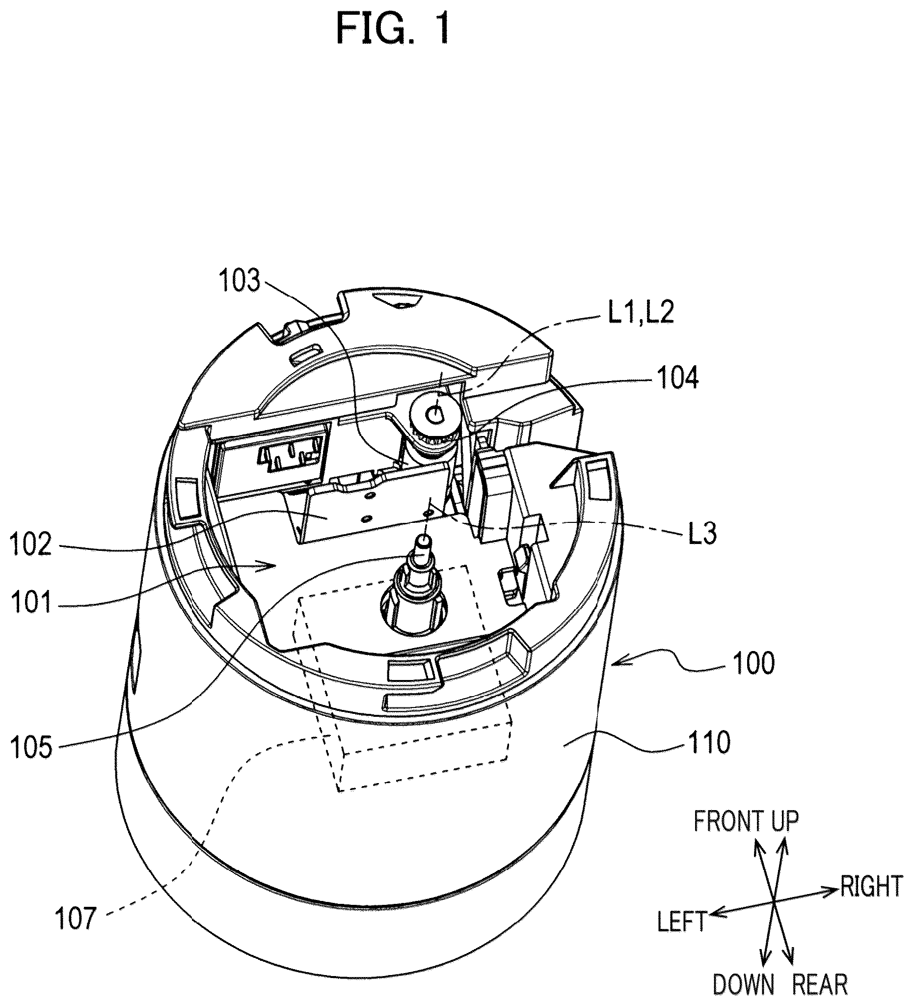
is a schematic perspective view of a printing device body.
A and 2 B are each a schematic perspective view of a printing cassette.
A and 3 B are each a schematic perspective view of a printing tape cassette illustrated in A .
is a schematic exploded perspective view of the printing cassette illustrated in A .
A and 5 B are each a schematic perspective view of an auxiliary tape cassette illustrated in A .
A and 6 B are each a schematic perspective view of a printing cassette.
A is a schematic perspective view of a printing tape cassette illustrated in A .
B is a schematic perspective view of an auxiliary tape cassette illustrated in A .
A and 8 B are each a schematic perspective view of a printing cassette.
A and 9 B are each a schematic perspective view of a printing tape cassette illustrated in A .
A and 10 B are each a schematic perspective view of an auxiliary tape cassette illustrated in A .
is a schematic perspective view of a printing cassette.
A and 12 B are each a schematic perspective view of a printing cassette.
is a schematic perspective view of a printing tape cassette illustrated in A .
is a schematic perspective view of a gear cassette illustrated in A .
A and 15 B are each a schematic perspective view of a printing cassette.
A and 16 B are each a schematic perspective view of a printing tape cassette illustrated in A .
A and 17 B are each a schematic perspective view of an auxiliary tape cassette illustrated in A .
is a schematic exploded perspective view of the auxiliary tape cassette illustrated in A .
is a schematic perspective view of a printing cassette.
A and 20 B are each a schematic perspective view of a printing cassette.
A and 21 B are each a schematic perspective view of a printing cassette.
1. FIRST EMBODIMENT
1-1. Configuration
A printing device is configured of a printing device body 100 shown in together with a printing cassette 10 shown in A and 2 B . This printing device is a device that prints on tape-like printing medium.
In the present embodiment, the axial direction of an output gear 21 will be called the up-down direction, a direction perpendicular to the up-down direction in which the output gear 21 and a take-up spool 16 are aligned will be called the front-rear direction, and a direction perpendicular to both the up-down direction and the front-rear direction will be called the left-right direction.
Printing Device Body
As shown in , the printing device body 100 is provided with a cassette accommodation part 101 , a print head 102 , a platen roller 103 , a platen gear 104 , a drive shaft 105 , a drive source 107 , and a housing 110 .
Cassette Housing Part
The cassette accommodation part 101 is a recess to which the printing cassette 10 is attached. The cassette accommodation part 101 is provided in the housing 110 . The cassette accommodation part 101 functions to position the printing cassette 10 .
Print Head
The print head 102 is disposed inside the cassette accommodation part 101 . The print head 102 has a plurality of heating elements whose heating is individually controlled.
Platen Roller
The platen roller 103 is disposed inside the cassette accommodation part 101 near the print head 102 so as to face the print head 102 . The platen roller 103 can pivot in a direction toward the print head 102 and in a direction away from the print head 102 . The platen roller 103 has a rotational axis L 1 that is parallel to the up-down direction.
Platen Gear
The platen gear 104 is coupled to the platen roller 103 . The platen gear 104 has a rotational axis L 2 . In the present embodiment, the rotational axis L 2 of the platen gear 104 and the rotational axis L 1 of the platen roller 103 are disposed on the same straight line. In other words, the rotational axis L 2 is colinear with the rotational axis L 1 . The platen gear 104 can pivot together with the platen roller 103 .
Drive Shaft
The drive shaft 105 is configured to be inserted into both the take-up spool 16 and an input gear 22 in the printing cassette 10 . The drive shaft 105 is configured to rotate the take-up spool 16 and input gear 22 .
The drive shaft 105 is disposed inside the cassette accommodation part 101 . The drive shaft 105 has a rotational axis L 3 that is parallel to the up-down direction. The drive shaft 105 is configured to rotate about the rotational axis L 3 by the drive source 107 .
Drive Source
The drive source 107 is configured to drive the drive shaft 105 to rotate. A mechanism including a motor and gears, for example, can be used as the drive source 107 .
Printing Cassette
The printing cassette 10 shown in A and 2 B is provided with a printing medium (i.e., a printing tape 11 A). The printing cassette 10 is attachable to and detachable from the printing device body 100 . The printing cassette 10 can be interchanged to replenish the printing medium and to change the type of printing media (e.g., the size, color, material, etc.).
The printing cassette 10 includes a printing tape cassette 30 , and an auxiliary tape cassette 40 . The printing cassette 10 is configured to be attached to the printing device body 100 in a state where the printing tape cassette 30 and auxiliary tape cassette 40 are coupled to each other.
Printing Tape Cassette
The printing tape cassette 30 shown in A and 3 B includes a printing tape case 35 that houses at least a portion of the printing tape 11 A. As shown in , the printing tape cassette 30 also includes a first roll 11 , a first supply spool 12 , and spacer films 13 A and 13 B.
First Roll
The first roll 11 is configured of the printing tape 11 A wound around the first supply spool 12 . Printing is performed on the printing tape 11 A. The front surface of the printing tape 11 A is printed by the print head 102 in the printing device body 100 and an ink ribbon 14 A (an example of an auxiliary tape).
The two spacer films 13 A and 13 B are disposed on respective outer sides of the first roll 11 in the up-down direction so as to sandwich the first roll 11 . The spacer films 13 A and 13 B are respectively disposed between the first roll 11 and a first case part 31 and between the first roll 11 and a second case part 32 .
First Supply Spool
The first supply spool 12 is rotatable about a rotational axis L 4 . The first supply spool 12 supplies the printing tape 11 A to the print head 102 by rotating as the platen roller 103 of the printing device body 100 conveys the printing tape 11 A. The rotational axis L 4 of the first supply spool 12 is parallel to the up-down direction. The rotational axis L 4 of the first supply spool 12 and the winding axis of the first roll 11 are the same axis.
Printing Tape Cassette
The printing tape case 35 includes the first case part 31 and the second case part 32 . Also, the printing tape case 35 has a first guide surface 35 A (see A and 3 B ) and a first discharge port 35 B (see A and 3 B ).
The first case part 31 constitutes the upper end portion of the printing tape case 35 . The second case part 32 constitutes the lower end portion of the printing tape case 35 . The second case part 32 is disposed below the first case part 31 and is coupled to the first case part 31 in the up-down direction. The first roll 11 is disposed in a space enclosed by the first case part 31 and second case part 32 .
The first case part 31 has a first side wall 31 A, and a first notch 31 B. The second case part 32 has a second side wall 32 A, a second notch 32 B, and a first positioning part 32 C.
The first side wall 31 A and second side wall 32 A constitutes a side surface, among the outer surfaces of the printing tape case 35 , that circumferentially surrounds the first roll 11 . The first notch 31 B is provided in the front portion (and specifically, the right-front portion) of the first side wall 31 A. The second notch 32 B is provided in the front portion (and specifically, the right-front portion) of the second side wall 32 A. The first notch 31 B and second notch 32 B are coupled together to constitute the first discharge port 35 B for the printing tape 11 A.
As shown in A and 2 B , part of the side surface of the printing tape case 35 constitutes the first guide surface 35 A. The first guide surface 35 A is configured to guide the printing tape 11 A discharged through the first discharge port 35 B of the printing tape case 35 .
The first discharge port 35 B is provided in the side surface of the printing tape case 35 for discharging the printing tape 11 A to an outside of the printing tape case 35 . The printing tape 11 A is discharged through the first discharge port 35 B in a radial direction of the first roll 11 . The discharged printing tape 11 A is conveyed downward from the first discharge port 35 B (i.e., toward the auxiliary tape cassette 40 ) while being wrapped around the first guide surface 35 A in a spiral shape having a central axis that is parallel to the up-down direction.
As shown in A , the first positioning part 32 C is a hole formed in a first coupling surface 35 C of the printing tape case 35 . The first coupling surface 35 C faces and contacts the auxiliary tape cassette 40 positioned below the first coupling surface 35 C in a state where the printing tape case 35 is inserted into the cassette accommodation part 101 . The first positioning part 32 C positions the printing tape case 35 relative to the auxiliary tape cassette 40 . A second positioning part 41 E on the auxiliary tape cassette 40 is inserted into the first positioning part 32 C.
The first coupling surface 35 C is a flat surface, among the outer surfaces of the printing tape case 35 , that crosses (and specifically is orthogonal to) the up-down direction. The auxiliary tape cassette 40 can be arranged on the first coupling surface 35 C.
Auxiliary Tape Cassette
The auxiliary tape cassette 40 shown in A and 5 B is attachable to and detachable from the printing tape cassette 30 . The auxiliary tape cassette 40 includes an auxiliary tape case 45 that houses at least part of the ink ribbon 14 A and at least part of a drive transmission unit 20 .
The auxiliary tape cassette 40 in the present embodiment is also a gear cassette that houses gears. As shown in , the auxiliary tape cassette 40 includes a second roll 14 , a second supply spool 15 , the take-up spool 16 , a clutch spring holder 17 , and the drive transmission unit 20 .
Second Roll
The second roll 14 is configured of the ink ribbon 14 A wound around the second supply spool 15 . The ink ribbon 14 A is used for printing the printing tape 11 A.
The ink ribbon 14 A is overlaid on the printing tape 11 A being conveyed in a head opening 42 B and is used for printing by the print head 102 . The ink ribbon 14 A that has been used to perform printing is taken up on the take-up spool 16 .
Rotational resistance is applied to the second roll 14 by a clutch spring (not shown) held in the clutch spring holder 17 . At least a portion of the second roll 14 is disposed in a position overlapping the first roll 11 in the up-down direction. In other words, at least a portion of the second roll 14 is overlapped with the first roll 11 as viewed in the up-down direction.
Second Supply Spool
The second supply spool 15 is rotatable about a rotational axis L 5 . The rotational axis L 5 of the second supply spool 15 is parallel to the rotational axis L 4 of the first supply spool 12 , i.e., parallel to the up-down direction. The rotational axis L 5 of the second supply spool 15 and the winding axis of the second roll 14 are the same axis. The second supply spool 15 supplies the ink ribbon 14 A to the head opening 42 B by rotating as the take-up spool 16 takes up the ink ribbon 14 A.
Take-Up Spool
The take-up spool 16 is rotatable around a rotational axis L 6 . The rotational axis L 6 of the take-up spool 16 is parallel to the rotational axis L 5 of the second supply spool 15 .
The take-up spool 16 is cylindrical and has a hollow area defined by an inner circumferential surface 16 A. Splines 16 B are provided on the inner circumferential surface 16 A of the take-up spool 16 . The drive shaft 105 of the printing device body 100 is configured to be coupled to the splines 16 B. When rotated by the drive shaft 105 , the take-up spool 16 takes up the ink ribbon 14 A that has been used to perform printing.
Drive Transmission Unit
In a state where the printing cassette 10 is attached to the printing device body 100 , the transmission mechanism 20 transmits the drive force of the drive source 107 received from the drive shaft 105 to the platen roller 103 and rotates the platen roller 103 at a rotational speed individually set for that printing cassette 10 .
The drive transmission unit 20 has the output gear 21 , the input gear 22 , and an idle gear 23 . The drive transmission unit 20 is disposed above the second roll 14 (i.e., near the printing tape cassette 30 ). In other words, the output gear 21 and input gear 22 are disposed in the auxiliary tape case 45 so as to be separated from the second roll 14 in the up-down direction.
Output Gear
The output gear 21 is an external gear provided for externally outputting a drive force used for conveying the printing tape 11 A. Specifically, the output gear 21 outputs the drive force to the platen gear 104 of the printing device body 100 . The output gear 21 has a rotational axis L 7 that is parallel to the rotational axis L 5 of the second supply spool 15 . A portion of the output gear 21 is exposed in a space that is in communication with the head opening 42 B.
The output gear 21 engages with the platen gear 104 in the space communicating with the head opening 42 B in a state where the printing cassette 10 is attached to the printing device body 100 (i.e., in a state where the auxiliary tape case 45 is accommodated in the cassette accommodation part 101 ).
Input Gear
The input gear 22 is indirectly engaged with the output gear 21 via the idle gear 23 and transmits a drive force to the output gear 21 .
The input gear 22 has an external gear 22 A, and a spool 22 B. The spool 22 B is a cylindrical internal gear having an inner circumferential surface provided with splines. The spool 22 B is fixed to one side surface of the external gear 22 A. The external gear 22 A is rotated together with the spool 22 B by the drive force of the drive source 107 inputted into the spool 22 B.
The input gear 22 has a rotational axis L 8 (i.e., the rotational axes of the external gear 22 A and spool 22 B). The rotational axis L 8 of the input gear 22 and the rotational axis L 6 of the take-up spool 16 are disposed on the same straight line. In other words, the rotational axis L 8 is colinear with the rotational axis L 6 . At least a portion of the input gear 22 is disposed in a position overlapping the first roll 11 in the up-down direction. In other words, at least a portion of the input gear 22 is overlapped with the first roll 11 as viewed in the up-down direction.
The rotational axis L 8 of the input gear 22 overlaps the hollow area of the take-up spool 16 in the up-down direction. In other words, the rotational axis L 8 and the hollow area of the take-up spool 16 are overlapped with each other as viewed in the up-down direction. Further, the lower end portion of the spool 22 B in the input gear 22 is inserted into the hollow area of the take-up spool 16 from above.
Therefore, the drive shaft 105 is simultaneously inserted into the take-up spool 16 and the input gear 22 in a state where the printing cassette 10 is attached to the printing device body 100 . As a result, the input gear 22 , although not directly coupled to the take-up spool 16 , is rotated together with the take-up spool 16 by the drive shaft 105 .
Idle Gear
The idle gear 23 is drivingly coupled to (i.e., engaged with) both the input gear 22 and the output gear 21 for transmitting the drive force inputted into the input gear 22 to the output gear 21 . Hence, the drive shaft 105 is configured to input a drive force indirectly to the output gear 21 via the input gear 22 and idle gear 23 .
The idle gear 23 is a stepped gear having an upstream gear 23 A engaged with the input gear 22 , and a downstream gear 23 B engaged with the output gear 21 . The upstream gear 23 A and downstream gear 23 B are coaxially juxtaposed. The downstream gear 23 B has a smaller diameter than the diameter of the upstream gear 23 A. Further, the downstream gear 23 B is disposed closer to the printing tape cassette 30 in the up-down direction than the upstream gear 23 A to the printing tape cassette 30 in the up-down direction (i.e., above the upstream gear 23 A).
The idle gear 23 transmits the drive force inputted into the input gear 22 to the output gear 21 after reducing the rotational speed of the drive force. That is, the drive transmission unit 20 includes a reduction mechanism whose reduction ratio is the transmission ratio obtained by dividing the rotational speed of the input gear 22 by the rotational speed of the output gear 21 .
Auxiliary Tape Case
The auxiliary tape case 45 has a third case part 41 , a fourth case part 42 , a fifth case part 43 , and a second guide surface 45 A (see A and 2 B ).
The third case part 41 constitutes the upper end portion of the auxiliary tape case 45 . The fifth case part 43 constitutes the lower end portion of the auxiliary tape case 45 . The fourth case part 42 is arranged below the third case part 41 and above the fifth case part 43 and is coupled to both the third case part 41 and the fifth case part 43 in the up-down direction.
The second roll 14 , second supply spool 15 , and take-up spool 16 are disposed in a space enclosed by the fourth case part 42 and fifth case part 43 . The idle gear 23 , the input gear 22 , and a portion of the output gear 21 are disposed in a space enclosed by the third case part 41 and fourth case part 42 .
The third case part 41 has a third side wall 41 A, a first gear support part 41 B, a second gear support part 41 C, a third gear support part 41 D, and the second positioning part 41 E (see B ). The third side wall 41 A constitutes the side surface, among the outer surfaces of the auxiliary tape case 45 , that is continuous with the side surface of the printing tape case 35 .
The first gear support part 41 B rotatably supports the output gear 21 . The second gear support part 41 C rotatably supports the input gear 22 . The third gear support part 41 D rotatably supports the idle gear 23 .
The second positioning part 41 E shown in B is provided on a second coupling surface 45 B of the auxiliary tape case 45 . The second coupling surface 45 B faces and contacts the printing tape cassette 30 positioned above the second coupling surface 45 B in a state where the auxiliary tape case 45 is inserted in the cassette accommodation part 101 .
The second coupling surface 45 B is a flat surface, among the outer surfaces of the auxiliary tape case 45 , that crosses (and specifically is orthogonal to) the up-down direction. The second coupling surface 45 B is parallel to the first coupling surface 35 C of the printing tape case 35 . The printing tape cassette 30 can be arranged on the second coupling surface 45 B.
The second positioning part 41 E is a cylindrical or columnar part that protrudes upward from the second coupling surface 45 B. When the auxiliary tape cassette 40 and the printing tape cassette 30 are coupled together, the second positioning part 41 E is inserted into the first positioning part 32 C of the printing tape case 35 , whereby the auxiliary tape cassette 40 is fixed in position relative to the printing tape cassette 30 in the front-rear and left-right directions.
The fourth case part 42 shown in has a fourth side wall 42 A, the head opening 42 B, a second discharge port 42 C, an inner guide wall 42 D, a first restricting part 42 E, and a ceiling wall 42 F. The fourth side wall 42 A constitutes a side surface, among the outer surfaces of the auxiliary tape case 45 , that circumferentially surrounds the second roll 14 .
The head opening 42 B is a notch formed by cutting off a portion of the fourth side wall 42 A. The head opening 42 B is a space in which the print head 102 is placed in a state where the printing cassette 10 is attached to the printing device body 100 .
In the head opening 42 B, printing is performed on the printing tape 11 A by the print head 102 . The head opening 42 B is open in the bottom of the auxiliary tape cassette 40 so that the print head 102 can be inserted from below. The printing tape 11 A and ink ribbon 14 A are bridged over the head opening 42 B in the left-right direction.
The printing tape 11 A on which printing has been performed is discharged to an outside of the printing cassette 10 through the second discharge port 42 C. That is, the second discharge port 42 C allows the printing tape 11 A to be discharged from the inside of the auxiliary tape case 45 to the outside thereof. The printed printing tape 11 A is discharged from the printing device to the outside thereof through the second discharge port 42 C.
The inner guide wall 42 D is a plate-like part having a front surface that guides the printing tape 11 A (i.e., contacts the printing tape 11 A from rear) in the left-right direction in the auxiliary tape case 45 . The inner guide wall 42 D constitutes part of the fourth side wall 42 A that guides the printing tape 11 A toward the second discharge port 42 C.
The inner guide wall 42 D is continuously provided from the fourth side wall 42 A. Additionally, the inner guide wall 42 D is disposed upstream of the head opening 42 B in the discharging direction of the printing tape 11 A and frontward of the head opening 42 B.
At least part of the inner guide wall 42 D is disposed at the same position as the second discharge port 42 C in the up-down direction. That is, at least part of the inner guide wall 42 D overlaps the second discharge port 42 C in a direction orthogonal to the up-down direction. In other words, at least part of the inner guide wall 42 D and the second discharge port 42 C are overlapped with each other as viewed in a direction orthogonal to the up-down direction. The printing tape 11 A is conveyed on the inner guide wall 42 D in a direction orthogonal to the up-down direction (and specifically, in the left-right direction).
The first restricting part 42 E restricts the printing tape 11 A, which is being conveyed along the second guide surface 45 A which is constituted by the inner guide wall 42 D, from moving in the width direction of the printing tape 11 A. Specifically, the first restricting part 42 E is disposed above the inner guide wall 42 D and has a bottom surface that is orthogonal to the up-down direction.
The ceiling wall 42 F is disposed frontward of the inner guide wall 42 D and is spaced apart from the inner guide wall 42 D. The space between the ceiling wall 42 F and inner guide wall 42 D constitutes a conveying path for the printing tape 11 A. The ceiling wall 42 F is connected to the first restricting part 42 E. The inner surface (i.e., rear surface) of the ceiling wall 42 F constitutes a restricting surface that is arranged to face the second guide surface 45 A (i.e., the inner guide wall 42 D).
The fifth case part 43 has a fifth side wall 43 A, and a second restricting part 43 B. The fifth side wall 43 A constitutes, in cooperation with the fourth side wall 42 A of the fourth case part 42 , the side surface of the auxiliary tape case 45 that circumferentially surrounds the second roll 14 .
The second restricting part 43 B restricts the printing tape 11 A, which is being conveyed along the second guide surface 45 A, from moving in the width direction of the printing tape 11 A. Specifically, the second restricting part 43 B is disposed below the inner guide wall 42 D of the fourth case part 42 and has a top surface that is orthogonal to the up-down direction. The second restricting part 43 B faces the first restricting part 42 E of the fourth case part 42 in the up-down direction.
The inner guide wall 42 D, ceiling wall 42 F, first restricting part 42 E, and second restricting part 43 B constitute an arm part 45 C. The arm part 45 C has an inner space through which the printing tape 11 A passes when being conveyed along the second guide surface 45 A of the auxiliary tape case 45 , as shown in B . After passing through the arm part 45 C, the printing tape 11 A is fed into the head opening 42 B.
In the arm part 45 C, the inner guide wall 42 D and ceiling wall 42 F restrict movement of the printing tape 11 A in the front-rear direction (i.e., the thickness direction) and the first restricting part 42 E and second restricting part 43 B restrict movement of the printing tape 11 A in the up-down direction (i.e., the width direction).
As shown in A and 2 B , part of the side surface of the auxiliary tape case 45 constitutes the second guide surface 45 A, which guides the printing tape 11 A supplied from outside the auxiliary tape case 45 (i.e., from the printing tape cassette 30 ) toward the second discharge port 42 C. The printing tape 11 A guided by the first guide surface 35 A of the printing tape case 35 is further guided toward the head opening 42 B by the second guide surface 45 A.
Conveyance and Printing of Printing Tape with the Printing Device Body
In a state where the printing cassette 10 is attached to the printing device body 100 , the printing tape 11 A is wrapped around the first guide surface 35 A of the printing tape case 35 and the second guide surface 45 A of the auxiliary tape case 45 to form a spiral portion 11 B whose angle of rotation about a central axis parallel to the up-down direction (i.e., the wound angle of the wrapped printing tape 11 A around the printing tape case 35 and auxiliary tape case 45 when viewed along the up-down direction) is 180 degrees or greater.
The spiral portion 11 B of the printing tape 11 A being conveyed is wrapped across the side surface of the printing tape case 35 and side surface of the auxiliary tape case 45 . Specifically, the spiral portion 11 B extends from the first discharge port 35 B of the printing tape case 35 to the inside of the arm part 45 C.
Each of the first guide surface 35 A and second guide surface 45 A has a curved surface that guides at least a portion of the spiral portion 11 B on the upstream side of the head opening 42 B in the discharging direction of the printing tape 11 A.
Specifically, the first guide surface 35 A is configured entirely of a curved surface. The second guide surface 45 A is also configured of a curved surface in all areas except the inside of the arm part 45 C (i.e., except the front surface of the inner guide wall 42 D).
The radius of curvature for at least part of the curved surface of the first guide surface 35 A and the radius of curvature for at least part of the curved surface of the second guide surface 45 A are each greater than one half the outer diameter of the second roll 14 .
In a state where the printing cassette 10 is attached to the printing device body 100 with the printing tape 11 A wrapped around the guide surfaces in this way, the print head 102 is disposed in the head opening 42 B at a position overlapping the printing tape 11 A and ink ribbon 14 A in the front-rear direction (i.e., in such a manner that the print head 102 is overlapped with the printing tape 11 A and ink ribbon 14 A as viewed in the front-rear direction).
The platen roller 103 conveys the printing tape 11 A into the head opening 42 B and presses the printing tape 11 A against the print head 102 , whose heating elements have been heated, through the ink ribbon 14 A. As a result, some ink provided on the surface of the ink ribbon 14 A is transferred onto the printing tape 11 A to print characters, symbols, and the like on the printing tape 11 A.
The platen roller 103 conveys the printed printing tape 11 A in the printing cassette 10 toward the outside of the printing cassette 10 . The platen roller 103 is rotated by the platen gear 104 , which is engaged with the output gear 21 . The platen roller 103 and platen gear 104 can pivot between a position separated from the printing cassette 10 and a position in which the platen gear 104 is engaged with the output gear 21 .
In a state where the auxiliary tape case 45 of the printing cassette 10 is inserted into the cassette accommodation part 101 , the drive shaft 105 is engaged with the input gear 22 and the platen gear 104 is engaged with the output gear 21 .
Specifically, the platen gear 104 comes into engagement with the output gear 21 when the platen roller 103 and platen gear 104 pivot toward the head opening 42 B of the printing cassette 10 in a state where the drive shaft 105 is inserted into both the take-up spool 16 and input gear 22 of the printing cassette 10 .
In a state where the printing cassette 10 is attached, the output gear 21 is rotated when the drive shaft 105 rotates the input gear 22 . Further, the platen gear 104 is rotated by the rotation of the output gear 21 , and the platen roller 103 is rotated by the rotation of the platen gear 104 .
Variation of the First Embodiment
A printing cassette 10 A shown in A and 6 B has a printing tape cassette 30 A, and an auxiliary tape cassette 40 A. The arm part 45 C provided on the auxiliary tape cassette 40 in the printing cassette 10 of A and 2 B is provided on the printing tape cassette 30 A of the printing cassette 10 A as an arm part 35 D.
As shown in A , the arm part 35 D of the printing tape cassette 30 A has a slit-like conveying path 35 E that enables the printing tape 11 A to pass through the inside of the arm part 35 D. The arm part 35 D is disposed to the front of the head opening 42 B in the auxiliary tape cassette 40 A shown in B (and specifically, to the front of the fourth side wall 42 A) with the arm part 35 D overlaid on the fourth side wall 42 A. The arm part 35 D is configured of a downwardly protruding plate part of the first case part 31 and a downwardly protruding plate part of the second case part 32 .
1-2. Effects
The following effects can be obtained according to the embodiments described above.
(1a) The first guide surface 35 A of the printing tape cassette 30 and the second guide surface 45 A of the auxiliary tape cassette 40 both suppress kinks and other problems in the printing tape 11 A being fed to the head opening 42 B. Therefore, the printing tape 11 A can be conveyed properly to the head opening 42 B provided in the auxiliary tape cassette 40 .
(1b) The first positioning part 32 C of the printing tape cassette 30 and the second positioning part 41 E of the auxiliary tape cassette 40 can suppress misalignment in the positions of the printing tape case 35 and auxiliary tape case 45 . As a result, stability in conveyance of the printing tape 11 A can be enhanced.
(1c) By arranging the drive transmission unit 20 in the auxiliary tape case 45 so as to be separated from the second roll 14 in the up-down direction, the size of the auxiliary tape case 45 can be reduced in the front-rear and left-right directions while enabling the printing tape 11 A to be suitably conveyed to the head opening 42 B.
(1d) The first restricting part 42 E and second restricting part 43 B can enhance stability in the conveyance of printing tape 11 A to the head opening 42 B.
(1e) The restricting surface of the ceiling wall 42 F can enhance stability in the conveyance of printing tape 11 A to the head opening 42 B.
2. SECOND EMBODIMENT
2-1. Configuration
A printing cassette 210 shown in A and 8 B is attached to the printing device body 100 of in place of the printing cassette 10 according to the first embodiment. The printing cassette 210 includes a printing tape cassette 230 , and an auxiliary tape cassette 240 .
Printing Tape Cassette
The printing tape cassette 230 shown in A and 9 B includes a printing tape case 235 that houses both the printing tape 11 A and the drive transmission unit 20 . In the present embodiment, the printing tape cassette 230 is also a gear cassette that houses gears.
The printing tape cassette 230 is configured by adding the third case part 41 of the auxiliary tape cassette 40 in the first embodiment to the printing tape cassette 30 in the first embodiment as a third case part 33 and by arranging the drive transmission unit 20 of the first embodiment inside the printing tape case 235 . The remaining configuration of the printing tape cassette 230 is identical to the printing tape cassette 30 in the first embodiment.
The third case part 33 constitutes the bottom portion of the printing tape case 235 and is coupled to the bottom of the second case part 32 . Part of the output gear 21 , the input gear 22 , and the idle gear 23 are disposed in a space enclosed by the second case part 32 and third case part 33 .
That is, the first roll 11 is disposed in a space enclosed by the first case part 31 and second case part 32 , and the output gear 21 and input gear 22 are arranged in the printing tape case 235 so to be separated from the first roll 11 in the up-down direction.
The lower surface of the third case part 33 constitutes the first coupling surface 35 C on which the auxiliary tape cassette 240 can be arranged. The first coupling surface 35 C has an insertion hole 33 A through which the input gear 22 is inserted in the up-down direction. The printing tape case 235 includes a positioning part for positioning the printing tape case 235 relative to the auxiliary tape cassette 240 . The positioning part is configured of the input gear 22 protruding from the first coupling surface 35 C.
Auxiliary Tape Cassette
The auxiliary tape cassette 240 shown in A and 10 B is configured by eliminating the third case part 41 and the drive transmission unit 20 from the auxiliary tape cassette 40 in the first embodiment.
The auxiliary tape cassette 240 includes an auxiliary tape case 245 that has the fourth case part 42 and fifth case part 43 . The remaining configuration of the auxiliary tape cassette 240 is identical to the auxiliary tape cassette 40 in the first embodiment.
In this embodiment, the top surface of the fourth case part 42 constitutes the second coupling surface 45 B on which the printing tape cassette 230 can be arranged. The second coupling surface 45 B has an opening 42 G into which the input gear 22 of the printing tape cassette 230 can be inserted. The opening 42 G constitutes a positioning part for positioning the auxiliary tape cassette 240 relative to the printing tape cassette 230 .
Variation of the Second Embodiment
As shown in , the printing cassette 210 of the second embodiment may include a cassette cover 46 that is arranged below the auxiliary tape cassette 240 .
A printing tape cassette 230 A shown in include an arm part 35 D similar to that on the printing tape cassette 30 A shown in A , and a frame part 34 that forms a space to house the auxiliary tape cassette 240 . The cassette cover 46 constitutes a cover for the frame part 34 .
2-2. Effects
The following effects can be obtained according to the embodiments described above.
(2a) In addition to the same advantages of the first embodiment, the printing cassette 210 can be configured to enable the ink ribbon 14 A to be replaced independently.
3. THIRD EMBODIMENT
3-1. Configuration
A printing cassette 310 shown in A and 12 B is attached to the printing device body 100 of in place of the printing cassette 10 according to the first embodiment. The printing cassette 310 includes the printing tape cassette 30 , the auxiliary tape cassette 240 , and a gear cassette 50 .
The printing tape cassette 30 in the printing cassette 310 is identical to that in the first embodiment. The auxiliary tape cassette 240 in the printing cassette 310 is identical to that in the second embodiment.
Gear Cassette
As shown in , the gear cassette 50 is disposed between the printing tape cassette 30 and the auxiliary tape cassette 240 . The gear cassette 50 is attachable to and detachable from the printing tape cassette 30 . The gear cassette 50 is also attachable to and detachable from the auxiliary tape cassette 240 .
As shown in , the gear cassette 50 includes a gear case 55 that houses the drive transmission unit 20 of the first embodiment. The gear case 55 has a sixth case part 51 , a seventh case part 52 , and a third guide surface 55 A.
The sixth case part 51 constitutes the upper end portion of the gear case 55 . The seventh case part 52 constitutes the lower end portion of the gear case 55 and is coupled to the bottom of the sixth case part 51 . The idle gear 23 , the input gear 22 , and part of the output gear 21 are disposed in a space enclosed by the sixth case part 51 and seventh case part 52 .
The sixth case part 51 includes a third positioning part 51 A. The third positioning part 51 A is provided on a third coupling surface 55 B. The third coupling surface 55 B faces and contacts the printing tape cassette 30 positioned above the third coupling surface 55 B in a state where the gear case 55 is inserted in the cassette accommodation part 101 .
The third positioning part 51 A is a cylindrical or columnar part that protrudes upward from the third coupling surface 55 B. When the gear cassette 50 and printing tape cassette 30 are coupled together, the third positioning part 51 A is inserted into the first positioning part 32 C of the printing tape case 35 .
As shown in , the bottom surface of the seventh case part 52 constitutes a fourth coupling surface 55 C on which the auxiliary tape cassette 240 can be arranged. The fourth coupling surface 55 C has an insertion hole 52 A through which the input gear 22 is inserted in the up-down direction. The gear case 55 includes a fourth positioning part, which is configured of the input gear 22 protruding from the fourth coupling surface 55 C.
As shown in A and 12 B , part of the side surface of the gear case 55 formed by the sixth case part 51 and seventh case part 52 constitutes the third guide surface 55 A that further guides the printing tape 11 A, which has been guided along the first guide surface 35 A of the printing tape cassette 30 , toward the second guide surface 45 A of the auxiliary tape cassette 240 . The third guide surface 55 A contacts the spiral portion 11 B of the printing tape 11 A.
3-2. Effects
The following effects are obtained according to the embodiment described above.
(3a) In addition to the same advantages described in the first embodiment, the printing cassette 310 can be configured so that each of the printing tape 11 A, drive transmission unit 20 , and ink ribbon 14 A is individually replaceable.
4. FOURTH EMBODIMENT
4-1. Configuration
A printing cassette 410 shown in A and 15 B is attached to the printing device body 100 of in place of the printing cassette 10 according to the first embodiment. The printing cassette 410 includes a printing tape cassette 430 , and an auxiliary tape cassette 440 .
Note that A shows the state of the printing cassette 410 in which a first case part 431 of the printing tape cassette 430 has been removed. B shows the state of the printing cassette 410 in which a third case part 441 of the auxiliary tape cassette 440 has been removed.
Printing Tape Cassette
The printing tape cassette 430 shown in A and 16 B includes a printing tape case 435 that houses the printing tape 11 A. Parts housed in the printing tape case 435 are the same as those described in the printing cassette 10 of the first embodiment.
The printing tape case 435 has the first case part 431 , a second case part 432 , a first guide surface 435 A, and a first discharge port 435 B. The first case part 431 constitutes the upper end portion of the printing tape case 435 . The second case part 432 constitutes the lower end portion of the printing tape case 435 and is coupled to the bottom of the first case part 431 .
The second case part 432 includes the first positioning part 32 C provided on the first coupling surface 35 C similar to that in the first embodiment. The second case part 432 also has an inner wall 432 A constituting the first guide surface 435 A, and an opening constituting the first discharge port 435 B. The inner wall 432 A surrounds the first roll 11 from the outer radial side.
The first discharge port 435 B is provided in the first coupling surface 35 C. The first discharge port 435 B discharges the printing tape 11 A to the outside of the printing tape case 435 in a direction crossing the first coupling surface 35 C (i.e., the up-down direction).
As shown in A , the first guide surface 435 A guides the printing tape 11 A drawn off the first roll 11 toward the first discharge port 435 B. The printing tape 11 A is wrapped around the first guide surface 435 A from the outer radial side of the first roll 11 while forming the spiral portion 11 B.
Auxiliary Tape Cassette
The auxiliary tape cassette 440 shown in A and 17 B includes an auxiliary tape case 445 that houses the ink ribbon 14 A and the drive transmission unit 20 . Parts housed in the auxiliary tape case 445 are the same as those in the printing cassette 10 of the first embodiment.
The auxiliary tape case 445 has the third case part 441 , a fourth case part 442 , a fifth case part 443 , a second guide surface 445 A, a first guide opening 445 D, and a second guide opening 445 E.
The third case part 441 constitutes the top surface of the auxiliary tape case 445 (i.e., a second coupling surface 445 B). The fifth case part 443 constitutes the lower end portion of the auxiliary tape case 445 . The fourth case part 442 is coupled to the top of the fifth case part 443 .
The third case part 441 includes the same second positioning part 41 E described in the first embodiment. As shown in , the third case part 441 also supports the drive transmission unit 20 . The third case part 441 is fitted inside an outer wall 442 A of the fourth case part 442 so as to close off the interior space of the fourth case part 442 from above.
The fourth case part 442 includes the same head opening 42 B, second discharge port 42 C, inner guide wall 42 D, first restricting part 42 E, and ceiling wall 42 F described in the first embodiment. The fourth case part 442 also has the outer wall 442 A, and an inner wall 442 B.
The inner wall 442 B surrounds the second roll 14 , second supply spool 15 , and take-up spool 16 from the outer radial side of the second roll 14 . Part of the outer surface of the inner wall 442 B constitutes the second guide surface 445 A.
The outer wall 442 A surrounds the inner wall 442 B from the outside thereof. As shown in B , the first guide opening 445 D is formed at the upper end portion of the auxiliary tape case 445 by the third case part 441 and fourth case part 442 . The first guide opening 445 D is in communication with the space between the outer wall 442 A and inner wall 442 B.
The first guide opening 445 D is formed in the second coupling surface 445 B (an example of the first outer surface) that is coupled to the printing tape cassette 430 . The printing tape 11 A discharged from the printing tape case 435 through the first discharge port 435 B is conveyed into the auxiliary tape case 445 through the first guide opening 445 D.
As shown in B , the printing tape 11 A fed into the auxiliary tape case 445 is wrapped around the second guide surface 445 A from the outer radial side of the second roll 14 while forming the spiral portion 11 B.
The fifth case part 443 shown in includes the same second restricting part 43 B described in the first embodiment. The fifth case part 443 also has an opening constituting the second guide opening 445 E. The second guide opening 445 E is provided in a bottom surface 445 C (an example of the second outer surface). The bottom surface 445 C sandwiches, in cooperation with the second coupling surface 445 B, the second roll 14 in the up-down direction within the auxiliary tape case 445 .
The second guide opening 445 E is in communication with the space between the outer wall 442 A and inner wall 442 B of the fourth case part 442 . Also, at least a portion of the second guide opening 445 E faces the first guide opening 445 D. Further, the second guide opening 445 E extends along the second guide surface 445 A to a position overlapping the arm part 45 C (i.e., the inner guide wall 42 D) so as to overlap the conveying path of the printing tape 11 A in the fourth case part 442 in the up-down direction.
Therefore, the printing tape 11 A inserted into the auxiliary tape case 445 through the first guide opening 445 D can be placed on the conveying path in the auxiliary tape case 445 while being drawn down to the bottom of the auxiliary tape case 445 through the second guide opening 445 E.
Note that the second guide opening 445 E does not overlap the entire second roll 14 in the up-down direction. In other words, the second guide opening 445 E and the entire second roll 14 are not overlapped as viewed in the up-down direction. That is, the second guide opening 445 E is formed in a shape that does not allow the second roll 14 to pass down through the fifth case part 443 and fall out of the auxiliary tape case 445 .
4-2. Effects
The following effects can be obtained according to the embodiment described above.
(4a) Providing the first guide surface 435 A and the second guide surface 445 A on inner surfaces of the respective cases can protect the printing tape 11 A.
(4b) The second guide opening 445 E enables the printing tape 11 A to be placed on the conveying path in the auxiliary tape case 445 while being pulled out of the printing tape cassette 430 .
5. OTHER EMBODIMENTS
While the invention has been described in conjunction with various example structures outlined above and illustrated in the figures, various alternatives, modifications, variations, improvements, and/or substantial equivalents, whether known or that may be presently unforeseen, may become apparent to those having at least ordinary skill in the art. Accordingly, the example embodiments of the disclosure, as set forth above, are intended to be illustrative of the invention, and not limiting the invention. Various changes may be made without departing from the spirit and scope of the disclosure. Therefore, the disclosure is intended to embrace all known or later developed alternatives, modifications, variations, improvements, and/or substantial equivalents. Some specific examples of potential alternatives, modifications, or variations in the described invention are provided below.
(5a) The printing device in the above embodiments is not limited to a device that prints with an ink ribbon. In place of the printing tape, the printing device may use a strip of thermal paper. In this case, a laminated tape may be used as the auxiliary tape, for example.
(5b) The printing cassette in the above embodiments need not necessarily be provided with a printing tape cassette. For example, a printing cassette 510 shown in includes a first case part 531 , a second case part 532 , and a third case part 533 . The first case part 531 supports the first roll 11 . The second case part 532 houses the drive transmission unit 20 in cooperation with the first case part 531 . The third case part 533 houses the second roll 14 in cooperation with the second case part 532 .
In the printing cassette 510 of , the first case part 531 , second case part 532 , and third case part 533 constitute an auxiliary tape cassette, and the first roll 11 is attachable to and detachable from the auxiliary tape cassette. Accordingly, the first roll 11 can be replaced independently without having to replace the printing tape cassette.
In the printing cassette 510 of , the side surface of the first case part 531 constitutes a first guide surface 535 A, and the side surface of the second case part 532 constitutes a second guide surface 545 A.
(5c) In the printing cassettes of the embodiments described above, a guide surface may be defined on the inner surface of one of the printing tape cassette and the auxiliary tape cassette and a guide surface may be defined on the outer surface of the other of the printing tape cassette and the auxiliary tape cassette.
For example, a printing cassette 610 shown in A and 20 B includes a printing tape cassette 630 and an auxiliary tape cassette 640 . A first guide surface 635 A is defined on the inner surface of the case for the printing tape cassette 630 , and a second guide surface 645 A is defined on the outer surface of the case for the auxiliary tape cassette 640 .
The printing tape 11 A guided along the first guide surface 635 A and discharged downward from a first discharge port 635 B of the printing tape cassette 630 is conveyed to the head opening 42 B through the arm part 45 C while being guided along the second guide surface 645 A.
Alternatively, a printing cassette 710 shown in the example of A and 21 B is provided with a printing tape cassette 730 , and an auxiliary tape cassette 740 . A first guide surface 735 A is defined on the outer surface of the case of the printing tape cassette 730 , while a second guide surface 745 A is defined on the inner surface of the case of the auxiliary tape cassette 740 .
The printing tape 11 A discharged from a first discharge port 735 B of the printing tape cassette 730 is guided along the first guide surface 735 A and second guide surface 745 A and conveyed to the head opening 42 B.
(5d) The printing cassettes in the above embodiments need not necessarily be provided with an arm part. That is, the cases of the printing tape cassette and auxiliary tape cassette need not necessarily possess: restricting parts that restrict the printing tape conveyed along the guide surfaces from moving in the width direction of the printing tape; and restricting surfaces facing the guide surfaces.
(5e) Functions possessed by a single component in the embodiments described above may be distributed among a plurality of components, and functions possessed by a plurality of components may be integrated into a single component. Additionally, some of the structures in the embodiments described above may be omitted. Further, at least some of the structures in the embodiments may be added to or used in place of structures in other embodiments. All aspects included in the technical concepts identified from descriptions in the claims are embodiments of the present disclosure.
Figures (20)
Citations
This patent cites (98)
- US3672603
- US3804227
- US3823808
- US3948382
- US4034935
- US4252450
- US4351619
- US4397574
- US4402619
- US4490059
- US4499513
- US4538931
- US4565128
- US4598780
- US4668961
- US4832514
- US4856921
- US5099378
- US5145268
- US5325114
- US5402954
- US5435657
- US5472286
- US5533818
- US5618119
- US5619244
- US5645360
- US5795085
- US5917532
- US5959652
- US6190067
- US6511238
- US2007/0172286
- US2007/0172293
- US2008/0084494
- US2014/0307038
- US2015/0283835
- US2017/0066265
- US2017/0190195
- US2020/0207115
- US2023/0294431
- US2023/0356537
- US102092201
- US103273748
- US106132715
- US107073982
- US111376619
- US116234704
- US116802060
- US0414544
- US2016411
- USS50-36734
- USS52-064310
- USS54-111914
- USS59-6460
- USS59-95180
- USS60-8072
- USS60-9657
- USS60-36255
- USS60-46254
- USS60-48456
- USS60-188821
- USS60-224571
- USS61-154877
- USS62-103179
- USS63-156762
- USH02-6173
- USH02-9562
- USH02-11379
- USH02-11380
- USH02-37568
- USH03-97181
- USH03-284973
- USH04-152176
- USH05-41834
- USH05-53956
- USH06-183117
- USH07-9745
- USH07-32710
- USH07-276755
- USH07-276757
- USH08-090877
- USH08-183204
- USH08-183232
- USH11-240232
- US2000-103149
- US2001-047713
- US2001130116
- US2002-211092
- US2004-255656
- US2007-502221
- US2008-261968
- US2009-196804
- US2011-037223
- US2011-148167
- US2011-150007
- US2014-170142
- US2005/018944