Abstract
A method for forming a laminate by stacking sheet materials containing reinforcing fibers includes a fixation step wherein a first region of the laminate in the length direction is fixed to a forming mold having a curved part which comprises at least either a convex shape or a concave shape in a predetermined direction; forming steps wherein the laminate is formed along the surface shape of the forming mold by pressing a second region of the laminate in the length direction, the first region of said laminate having been fixed in the fixation step, against the forming mold by means of a forming jig; and an installation step wherein a holding jig, which holds a state where the laminate is pressed against the curved part, is installed onto the curved part, while maintaining the state where the laminate is pressed against the forming mold by means of the forming jig.
Claims (3)
1 . A forming method of forming a laminate that is obtained by laminating a plurality of sheet-shaped materials including reinforcing fibers, the forming method comprising: a fixation step of fixing a first end of the laminate in a longitudinal direction to a forming die that includes a curved portion having at least one of a concave shape and a convex shape along a predetermined direction; a disposition step of disposing a forming jig having a rod shape extending in a width direction of the laminate so as to come into contact with the first end of the laminate fixed in the fixation step; a forming step of forming the laminate along a surface shape of the forming die by moving the forming jig from the first end of the laminate to a second end of the laminate along the predetermined direction in a state where the forming jig disposed in the disposition step presses the laminate against the forming die; and an installation step of installing a holding jig on the forming die over which the forming jig has passed, the holding jig maintaining a state where the laminate is pressed against the curved portion, wherein the holding jig includes a first holding member and a second holding member, the first holding member having a shape that corresponds to the curved portion of the forming die, the second holding member having a shape that corresponds to a flat surface of the forming die, the flat surface being connected to the curved portion of the forming die, in the installation step, the first holding member is moved from a position separated from the forming die to a position close to the forming die so that the first holding member that maintains a state where the laminate is pressed against the curved portion is installed on the curved portion as the forming jig passes over the curved portion and the laminate contacts with the curved portion, and the second holding member is moved from a position separated from the forming die to a position close to the forming die so that the second holding member that maintains a state where the laminate is pressed against the flat surface is installed on the flat surface as the forming jig passes over a position on the flat surface that faces the second holding member and the laminate contacts with the position on the flat surface, and in the forming step, the forming jig reaches to the second end after the first holding member is pressed against the curved portion and the second holding member is pressed against the flat surface in the installation process.
Show 2 dependent claims
2 . The forming method according to claim 1 , wherein a shape of the holding jig includes at least one of a concave shape or a convex shape along the width direction of the laminate, and the forming jig has a shape divided into a plurality of parts along the width direction of the laminate.
3 . The forming method according to claim 1 , wherein the curved portion is a portion having the concave shape along the predetermined direction.
Full Description
Show full text →
RELATED APPLICATIONS
The present application is a National Phase of International Application Number PCT/JP2020/025592 filed Jun. 29, 2020.
TECHNICAL FIELD
The present disclosure relates to a forming method of forming a laminate obtained by laminating a plurality of sheet-shaped materials including reinforcing fibers and to a forming device.
BACKGROUND ART
A composite structural member of an aircraft has a certain cross-sectional shape, and as a method of manufacturing the composite structural member, there is known a method of pressing a laminate that is obtained by laminating a plurality of sheet-shaped materials including reinforcing fibers against a forming die so as to form the laminate into a target shape (for example, refer to PTL 1 and PTL 2).
Disclosed in PTL 1 is a technique in which forming a ply installed on a mandrel by pressing the ply against a forming surface of the mandrel by means of a bladder is repeated to form a composite material in which a plurality of plies are laminated on each other. Disclosed in PTL 2 is a technique in which a plate-shaped material installed on an upper surface of a forming tool is pressed against a side surface and a flange surface of the forming tool by means of a bladder so that the plate-shaped material is formed.
CITATION LIST
Patent Literature
•
• [PTL 1] U.S. Unexamined Patent Application Publication No. 2017-0021534 • [PTL 2] U.S. Pat. No. 8,556,618
SUMMARY OF INVENTION
Technical Problem
However, in the case of PTL 1, the bladder is withdrawn after the ply is pressed against the forming surface of the mandrel. Therefore, a portion of the ply from which the bladder is withdrawn may be separated from the forming surface and may be deformed into a shape different from the surface shape of the mandrel. Similarly, in the case of PTL 2, the bladder is withdrawn after the plate-shaped material is pressed against a forming surface of the forming tool and the plate-shaped material is cured thereafter. Therefore, a portion of the plate-shaped material from which the bladder is withdrawn may be separated from the forming surface and may be deformed into a shape different from the surface shape of the forming tool. Particularly, in a case where a concave portion is formed between a side surface and a flange surface as in the case of the forming tool of PTL 2, it is difficult to make a bladder fit in with the shape of the concave portion and to appropriately press a plate-shaped member and thus there is a probability that the plate-shaped member cannot be appropriately formed along the shape of the concave portion.
The present disclosure has been made in view of such circumstances and an object thereof is to provide a forming method and a forming device with which it is possible to reliably maintain a state where a laminate obtained by laminating a plurality of sheet-shaped materials including reinforcing fibers is formed along the surface shape of a forming die.
Solution to Problem
According to an aspect of the present disclosure, there is provided a forming method of forming a laminate that is obtained by laminating a plurality of sheet-shaped materials including reinforcing fibers, the forming method including: a fixation step of fixing a first region of the laminate in a longitudinal direction to a forming die that includes a curved portion having at least one of a concave shape and a convex shape along a predetermined direction; a forming step of forming the laminate along a surface shape of the forming die by pressing a second region of the laminate, of which the first region is fixed in the fixation step, in the longitudinal direction against the forming die by means of a forming jig; and an installation step of installing a holding jig on the curved portion in a state where the forming jig presses the laminate against the forming die, the holding jig maintaining a state where the laminate is pressed against the curved portion.
According to an aspect of the present disclosure, there is provided a forming device forming a laminate that is obtained by laminating a plurality of sheet-shaped materials including reinforcing fibers, the forming device including: a forming die that includes a curved portion having at least one of a concave shape and a convex shape along a predetermined direction and to which a first region of the laminate in a longitudinal direction is fixed; a forming jig that forms the laminate along a surface shape of the forming die by pressing a second region of the laminate, of which the first region is fixed to the forming die, in the longitudinal direction against the forming die; a holding jig that maintains a state where the laminate is pressed against the curved portion; and an installation mechanism that installs the holding jig on the curved portion in a state where the forming jig presses the laminate against the forming die.
Advantageous Effects of Invention
According to the aspects of the present disclosure, it is possible to provide a forming method and a forming device with which it is possible to reliably maintain a state where a laminate obtained by laminating a plurality of sheet-shaped materials including reinforcing fibers is formed along the surface shape of a forming die.
BRIEF DESCRIPTION OF DRAWINGS
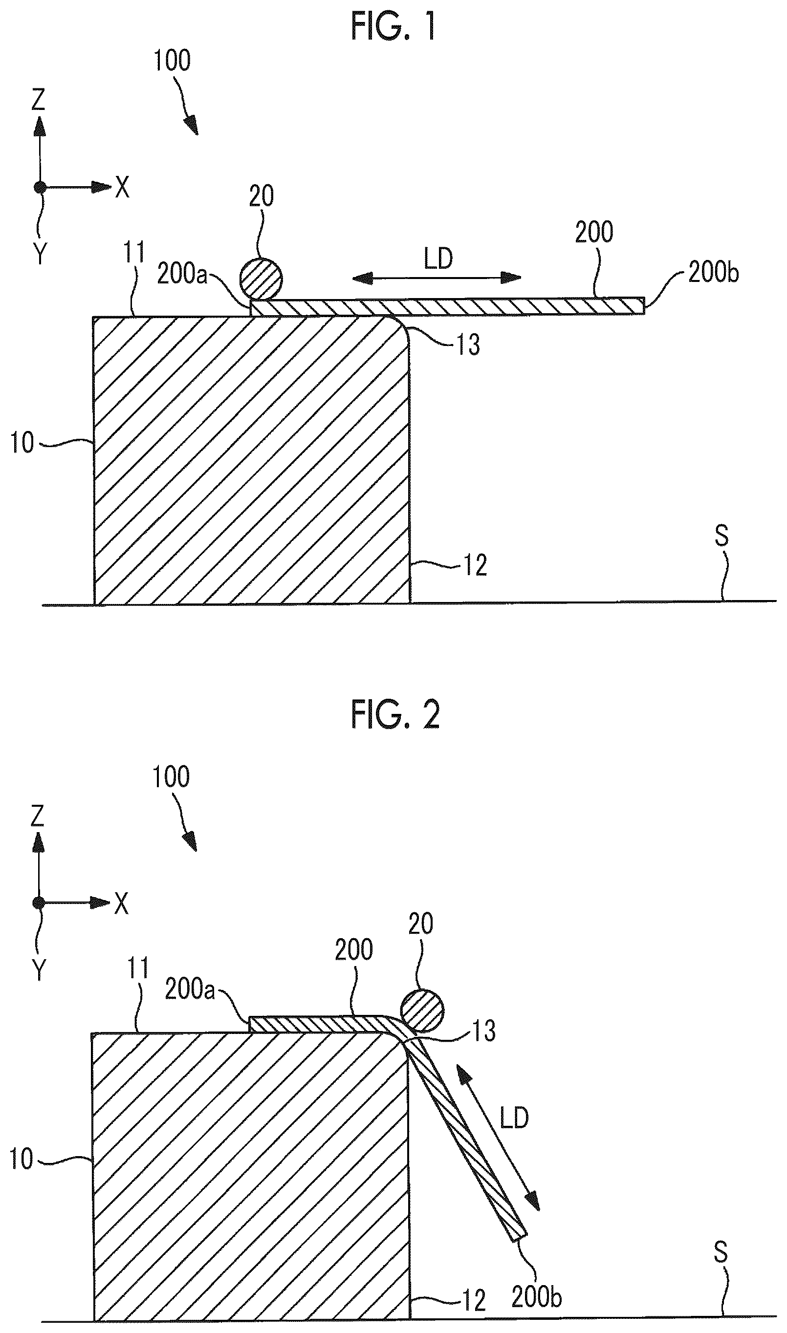
is a cross-sectional view that shows a forming device according to a first embodiment of the present disclosure and that shows a state before the forming of a laminate.
is a cross-sectional view that shows the forming device according to the first embodiment of the present disclosure and that shows a state during the forming of the laminate.
is a cross-sectional view that shows the forming device according to the first embodiment of the present disclosure and that shows a state during the forming of the laminate.
is a cross-sectional view that shows the forming device according to the first embodiment of the present disclosure and that shows a state where a first holding jig is installed on a curved surface during the forming of the laminate.
is a cross-sectional view that shows the forming device according to the first embodiment of the present disclosure and that shows a state where the forming of the laminate is finished.
is a flowchart showing a forming method according to the first embodiment of the present disclosure.
is a cross-sectional view that shows a forming device according to a second embodiment of the present disclosure and that shows a state before the forming of a laminate.
is a cross-sectional view that shows the forming device according to the second embodiment of the present disclosure and that shows a state during the forming of the laminate.
is a cross-sectional view that shows the forming device according to the second embodiment of the present disclosure and that shows a state during the forming of the laminate.
is a cross-sectional view that shows the forming device according to the second embodiment of the present disclosure and that shows a state where the forming of the laminate is finished.
is a cross-sectional view that shows a forming device according to a third embodiment of the present disclosure and that shows a state during the forming of a laminate.
is a cross-sectional view that shows the forming device according to the third embodiment of the present disclosure and that shows a state where the forming of the laminate is finished.
is a cross-sectional view that shows a forming device according to a fourth embodiment of the present disclosure and that shows a state before the forming of a laminate.
is a cross-sectional view that shows the forming device according to the fourth embodiment of the present disclosure and that shows a state during the forming of the laminate.
is a cross-sectional view that shows the forming device according to the fourth embodiment of the present disclosure and that shows a state where the forming of the laminate is finished.
is a cross-sectional view that shows a forming device according to a fifth embodiment of the present disclosure and that shows a state before the forming of a laminate.
is a cross-sectional view that shows the forming device according to the fifth embodiment of the present disclosure and that shows a state during the forming of the laminate.
is a cross-sectional view that shows the forming device according to the fifth embodiment of the present disclosure and that shows a state where the forming of the laminate is finished.
is a cross-sectional view that shows a forming device according to a sixth embodiment of the present disclosure and that shows a state before the forming of a laminate.
is a cross-sectional view that shows the forming device according to the sixth embodiment of the present disclosure and that shows a state during the forming of the laminate.
is a cross-sectional view that shows the forming device according to the sixth embodiment of the present disclosure and that shows a state where the forming of the laminate is finished.
DESCRIPTION OF EMBODIMENTS
First Embodiment
Hereinafter, a forming device 100 according to a first embodiment of the present disclosure and a forming method in which the forming device 100 is used will be described with reference to the drawings. to 4 are cross-sectional views showing the forming device 100 according to the present embodiment. shows a state before the forming of a laminate 200 . to 4 show a state during the forming of the laminate 200 . shows a state where a first holding jig 31 is installed on a curved surface 13 of a forming die 10 . shows a state where the forming of the laminate 200 is finished.
The forming device 100 of the present embodiment is a device that forms the laminate 200 , which is obtained by laminating sheet-shaped materials including reinforcing fibers, along the surface shape of the forming die 10 . The laminate 200 is obtained by laminating a plurality of sheet-shaped composite materials in a flat shape. The composite materials constituting the laminate 200 are sheet-shaped intermediate forming materials in which the reinforcing fibers and matrix resins attached thereto are semi-integrated with each other.
The reinforcing fibers included in the composite materials are, for example, carbon fibers, glass fibers, aramid fibers, or the like. As the matrix resins included in the composite materials, thermosetting resins or thermoplastic resins can be used. Examples of the thermosetting matrix resins include an epoxy resin, unsaturated polyester, vinyl ester, phenol, cyanate ester, and polyimide.
Examples of the thermoplastic matrix resins include polyetheretherketone (PEEK), polyethylene terephthalate (PET), polybutylene terephthalate (PBT), nylon 6 (PA6), nylon 66 (PA66), polyphenylene sulfide (PPS), polyetherimide (PEI), and polyetherketoneketone (PEKK).
In a case where thermoplastic resins are used as the matrix resins, the forming die 10 and a holding jig 30 which will be described later include heating mechanisms (not shown) that can heat the thermoplastic resins to a temperature equal to or higher than the softening point thereof. It is possible to form the laminate 200 including the thermoplastic resins along the surface shape of the forming die 10 by heating the thermoplastic resins to a temperature equal to or higher than the softening point by means of the heating mechanisms.
As the laminate 200 , a laminate that is formed in a flat shape by laminating a plurality of sheet-shaped reinforcing fibers (dry sheets) including no matrix resin may be used. In a case where a plurality of sheet-shaped reinforcing fibers including no matrix resin are used, a resin transfer molding (RTM) method, in which the laminate 200 formed along the surface shape of the forming die 10 is disposed on a molding tool (not shown) and a resin material is injected into the molding tool and is caused to infiltrate the reinforcing fibers so that molding is performed, is used.
As shown in to 4 , the forming device 100 of the present embodiment includes the forming die 10 , a forming jig 20 , the holding jig 30 , and an installation mechanism 40 . The forming device 100 shown in to 5 is disposed in a three-dimensional space. An X-axis, an Y-axis, and a Z-axis shown in to 5 are axes that intersect each other in the three-dimensional space. The X-axis is an axis extending along an installation surface S on which the forming die 10 is installed, and the Z-axis is an axis extending in a direction orthogonal to the installation surface S on which the forming die 10 is installed. The Y-axis is an axis orthogonal to both of the X-axis and the Z-axis and is an axis extending along a paper surface depth direction of to 5 .
The forming die 10 is a block-shaped die having a surface shape for forming the laminate 200 and is formed of a metallic material, for example. As the surface shape for forming the laminate 200 , the forming die 10 includes an upper surface 11 , a side surface 12 , and a curved surface (curved portion) 13 . It will be assumed that the cross-sectional shape of the forming die 10 of the present embodiment is the same for any position in a direction along the Y-axis. However, other configurations may also be adopted. The forming die 10 may have a shape including at least one of a concave shape or a convex shape along the Y-axis, for example.
The upper surface 11 of the forming die 10 is a surface extending flat along the X-axis. The side surface 12 of the forming die 10 is a surface extending flat along the Z-axis. The curved surface 13 is a surface that connects the upper surface 11 and the side surface 12 to each other and that has an arc-like shape in which the normal direction of the surface gradually changes toward the side surface 12 from the upper surface 11 along the X-axis with a transition from a surface extending along the X-axis to a surface extending along the Z-axis. The curved surface 13 is a portion having a convex shape along an X-axis direction (predetermined direction).
Regarding the forming die 10 , the upper surface 11 extends flat along the X-axis, the side surface 12 extends flat along the Z-axis, and the curved surface 13 is an arc-like surface connecting the upper surface 11 and the side surface 12 . However, other configurations may also be adopted. For example, the upper surface 11 may be a surface extending in a direction different from the X-axis and may be a surface that is not flat. In addition, the side surface 12 may be a surface extending in a direction different from the Z-axis and may be a surface that is not flat. In addition, the curved surface 13 may have any convex shape different from an arc-like shape.
The forming jig 20 is a jig that presses the other end (second region) 200 b of the laminate 200 , of which the one end (first region) 200 a is fixed to the forming die 10 , in a longitudinal direction LD against the forming die 10 so as to form the laminate 200 along the surface shape of the forming die 10 . The forming jig 20 of the present embodiment is a member that is formed in a rod-like shape extending in a width direction (Y-axis direction) of the laminate 200 and that has a circular cross section. The forming jig 20 forms the laminate 200 along the surface shape of the forming die 10 by continuously moving from the one end 200 a to the other end 200 b of the laminate 200 while pressing the laminate 200 against a surface of the forming die 10 .
As described above, the forming die 10 may have a shape including at least one of a concave shape or a convex shape along the Y-axis, for example. In this case, it is preferable that the forming jig 20 has a shape divided into a plurality of parts along the width direction (Y-axis direction) of the laminate 200 instead of being a single rod-shaped member. By being divided into a plurality of parts along the width direction of the laminate 200 , the forming jig 20 becomes able to be disposed along a shape at each position in the width direction. Accordingly, it is possible to appropriately form the laminate along the shape of the forming die 10 in the Y-axis direction in comparison with the case of a single rod-shaped member.
As shown in to 5 , the holding jig 30 is a member that maintains a state where the laminate 200 that is formed by the forming jig 20 along the surface shape of the forming die 10 is pressed against the upper surface 11 , the side surface 12 , and the curved surface 13 . The holding jig 30 includes a first holding jig 31 , a second holding jig 32 , and a third holding jig 33 .
The shape of a surface of the holding jig 30 that comes into contact with the laminate 200 is a shape that coincides with the shape of an outer peripheral surface of the laminate 200 formed along the surface shape of the forming die 10 . The shape of a surface of the first holding jig 31 that comes into contact with the laminate 200 is a shape that corresponds to the curved surface 13 of the forming die 10 . The shapes of surfaces of the second holding jig 32 and the third holding jig 33 that come into contact with the laminate 200 are shapes that correspond to the side surface 12 of the forming die 10 .
Although the holding jig 30 shown in to 5 includes the three holding jigs which are the first holding jig 31 , the second holding jig 32 , and the third holding jig 33 , other configurations may also be adopted. For example, the first holding jig 31 corresponding to the curved surface 13 of the forming die 10 may be a combination of a plurality of holding jigs. In addition, for example, each of the second holding jig 32 and the third holding jig 33 having shapes corresponding to the side surface 12 of the forming die 10 may be a single holding jig or a combination of three or more holding jigs.
As shown in to 5 , the installation mechanism 40 is a mechanism that installs the holding jig 30 on the laminate 200 in a state where the laminate 200 is pressed against the forming die 10 by the forming jig 20 . The installation mechanism 40 includes a first installation unit 41 , a second installation unit 42 , and a third installation unit 43 . The first installation unit 41 installs the first holding jig 31 on the curved surface 13 of the forming die 10 . The second installation unit 42 installs the second holding jig 32 on the side surface 12 of the forming die 10 . The third installation unit 43 installs the third holding jig 33 on the side surface 12 of the forming die 10 .
Next, a forming method performed by the forming device 100 according to the present embodiment will be described with reference to . is a flowchart showing the forming method according to the present embodiment.
In step S 101 (fixation step), the one end 200 a of the laminate 200 in the longitudinal direction LD is fixed to the forming die 10 . For example, the laminate 200 is fixed to the forming die 10 with the one end 200 a sandwiched by a clamp (not shown) attached to the forming die 10 .
In step S 102 (disposition step), the rod-shaped forming jig 20 that extends in the width direction of the laminate 200 is disposed to come into contact with the one end 200 a of the laminate 200 that is fixed to the forming die 10 in step S 101 . When the forming jig 20 is disposed, a state as shown in is achieved.
In step S 103 (forming start step), the other end 200 b of the laminate 200 is pressed against the forming die 10 by the forming jig 20 so that a forming step of forming the laminate 200 along the surface shape of the forming die 10 is started. The forming step is a series of steps of moving the forming jig 20 along the longitudinal direction LD from the one end 200 a to the other end 200 b of the laminate 200 in the longitudinal direction LD. In the forming step, the forming jig 20 is moved from the one end 200 a to the other end 200 b in the longitudinal direction LD in a state where the laminate 200 is pressed against the forming die 10 by the forming jig 20 . The forming jig 20 moves while maintaining a state where the forming jig 20 is in contact with the laminate 200 and the laminate 200 is pressed against the forming die 10 .
When the forming step is started in step S 103 , the forming jig 20 is moved along the X-axis from the one end 200 a of the laminate 200 to the curved surface 13 of the forming die 10 by means of a forming mechanism (not shown). When the forming jig 20 reaches the curved surface 13 , a state as shown in is achieved. When the forming jig 20 passes over the curved surface 13 and reaches the side surface 12 , a state as shown in is achieved.
In step S 104 (first installation step), the first holding jig 31 that maintains a state where the laminate 200 is pressed against the curved surface 13 is installed on the curved surface 13 as the forming jig 20 passes over the curved surface 13 and reaches the side surface 12 . After the forming jig 20 passes over the curved surface 13 , the installation mechanism 40 moves to a position close to the forming die 10 and a state as shown in is achieved. The installation mechanism 40 may be fixed at a predetermined position with respect to the forming die 10 .
Thereafter, by means of the first installation unit 41 , the installation mechanism 40 moves the first holding jig 31 to a position (position shown in ) close to the forming die 10 from a position (position shown in ) separated from the forming die 10 and installs the first holding jig 31 on a position at which the first holding jig 31 comes into contact with the laminate 200 formed along the shape of the curved surface 13 .
As shown in , when the first installation unit 41 installs the first holding jig 31 on the curved surface 13 , the forming jig 20 is in a state of pressing the laminate 200 against the forming die 10 . Since the forming jig 20 is not withdrawn from the laminate 200 when the first holding jig 31 is installed on the curved surface 13 , the laminate 200 is not deformed into a shape different from the surface shape of the forming die 10 .
In step S 105 (second installation step), the second holding jig 32 that maintains a state where the laminate 200 is pressed against the side surface 12 is installed on the side surface 12 as the forming jig 20 passes over a position on the side surface 12 that faces the second holding jig 32 . By means of the second installation unit 42 , the installation mechanism 40 moves the second holding jig 32 to a position (position shown in ) close to the forming die 10 from a position (position shown in ) separated from the forming die 10 and installs the second holding jig 32 on a position at which the second holding jig 32 comes into contact with the laminate 200 formed along the shape of the side surface 12 .
In step S 106 (third installation step), the third holding jig 33 that maintains a state where the laminate 200 is pressed against the side surface 12 is installed on the side surface 12 as the forming jig 20 passes over a position on the side surface 12 that faces the third holding jig 33 . By means of the third installation unit 43 , the installation mechanism 40 moves the third holding jig 33 to a position (position shown in ) close to the forming die 10 from a position (position shown in ) separated from the forming die 10 and installs the third holding jig 33 on a position at which the third holding jig 33 comes into contact with the laminate 200 formed along the shape of the side surface 12 .
In step S 107 (forming end step), when the forming jig 20 is further moved toward the other end 200 b of the laminate 200 along the Z-axis by the forming mechanism, the forming jig 20 reaches the other end 200 b of the laminate 200 . When the forming jig 20 reaches the other end 200 b of the laminate 200 , a state as shown in is achieved and each step of the forming method shown in ends.
According to the forming method of the present embodiment, the one end 200 a of the laminate 200 in the longitudinal direction LD is fixed to the forming die 10 including the curved surface 13 having a convex shape and the other end 200 b of the laminate 200 in the longitudinal direction LD is pressed against the forming die 10 so that the laminate 200 is formed along the surface shape of the forming die 10 . The first holding jig 31 is installed on the curved surface 13 of the laminate 200 formed along the surface shape of the forming die 10 in a state where the laminate 200 is pressed against the forming die 10 by the forming jig 20 .
Since the forming jig 20 is in a state of pressing the laminate 200 against the forming die 10 at the time of installation of the first holding jig 31 , the laminate 200 is not deformed into a shape different from the surface shape of the forming die 10 with the forming jig 20 withdrawn from the laminate 200 . Therefore, it is possible to reliably maintain a state where the laminate 200 , which is obtained by laminating a plurality of sheet-shaped materials including reinforcing fibers, is formed along the surface shape of the forming die 10 .
Second Embodiment
Next, a forming device 100 A according to a second embodiment of the present disclosure and a forming method in which the forming device 100 A is used will be described with reference to the drawings.
The present embodiment is a modification example of the first embodiment, is the same as the first embodiment except for a case particularly described below, and the description thereof will be omitted below.
The forming die 10 of the first embodiment includes the curved surface 13 which is a portion having a convex shape along the X-axis direction. In contrast, a forming die 10 A of the present embodiment includes a curved surface 16 which is a portion having a concave shape along the X-axis direction.
to 10 are cross-sectional views showing the forming device 100 A according to the present embodiment. shows a state before the forming of a laminate 200 . to 9 show a state during the forming of the laminate 200 . shows a state where the forming of the laminate 200 is finished.
As the surface shape for forming the laminate 200 , the forming die 10 A of the present embodiment includes a vertical surface 14 , a horizontal surface 15 , and the curved surface (curved portion) 16 . It will be assumed that the cross-sectional shape of the forming die 10 A of the present embodiment is the same for any position in a direction along the Y-axis. However, other configurations may also be adopted. The forming die 10 A may have a shape including at least one of a concave shape or a convex shape along the Y-axis, for example.
The vertical surface 14 of the forming die 10 A is a surface extending flat along the Z-axis. The horizontal surface 15 of the forming die 10 A is a surface extending flat along the X-axis. The curved surface 16 is a surface that connects the vertical surface 14 and the horizontal surface 15 to each other and that has an arc-like shape in which the normal direction of the surface gradually changes toward the horizontal surface 15 from the vertical surface 14 along the X-axis with a transition from a surface extending along the Z-axis to a surface extending along the X-axis. The curved surface 16 is a portion having a concave shape along an X-axis direction (predetermined direction).
Regarding the forming die 10 A, the vertical surface 14 extends flat along the Z-axis, the horizontal surface 15 extends flat along the X-axis, and the curved surface 16 is an arc-like surface connecting the vertical surface 14 and the horizontal surface 15 . However, other configurations may also be adopted. For example, the vertical surface 14 may be a surface extending in a direction different from the Z-axis and may be a surface that is not flat. In addition, the horizontal surface 15 may be a surface extending in a direction different from the X-axis and may be a surface that is not flat. In addition, the curved surface 16 may have any concave shape different from an arc-like shape.
As shown in , a holding jig 30 A is a member that maintains a state where the laminate 200 that is formed by the forming jig 20 along the surface shape of the forming die 10 A is pressed against the vertical surface 14 , the horizontal surface 15 , and the curved surface 16 . The holding jig 30 A includes a first holding jig 31 A, a second holding jig 32 A, and a third holding jig 33 A.
The shape of a surface of the holding jig 30 A that comes into contact with the laminate 200 is a shape that coincides with the shape of an outer peripheral surface of the laminate 200 formed along the surface shape of the forming die 10 A. The shape of a surface of the first holding jig 31 A that comes into contact with the laminate 200 is a shape that corresponds to the vertical surface 14 of the forming die 10 A. The shape of a surface of the second holding jig 32 A that comes into contact with the laminate 200 is a shape that corresponds to the curved surface 16 of the forming die 10 A. The shape of a surface of the third holding jig 33 A that comes into contact with the laminate 200 is a shape that corresponds to the horizontal surface 15 of the forming die 10 A.
Although the holding jig 30 A shown in includes the three holding jigs which are the first holding jig 31 A, the second holding jig 32 A, and the third holding jig 33 A, other configurations may also be adopted. For example, at least one of the first holding jig 31 A, the second holding jig 32 A, and the third holding jig 33 A may be a combination of two or more holding jigs.
As shown in , an installation mechanism 40 A is a mechanism that installs the holding jig 30 A on the laminate 200 in a state where the laminate 200 is pressed against the forming die 10 A by the forming jig 20 . The installation mechanism 40 A includes a first installation unit 41 A, a second installation unit 42 A, and a third installation unit 43 A. The first installation unit 41 A installs the first holding jig 31 A on the vertical surface 14 of the forming die 10 A. The second installation unit 42 A installs the second holding jig 32 A on the curved surface 16 of the forming die 10 A. The third installation unit 43 A installs the third holding jig 33 A on the horizontal surface 15 of the forming die 10 A.
Next, a forming method performed by the forming device 100 A according to the present embodiment will be described. The forming method of the present embodiment is a modification example of the forming method of the first embodiment shown in . In step S 101 (fixation step) shown in , the forming device 100 A enters a state as shown in . In step S 102 (disposition step) shown in , the forming device 100 A enters a state as shown in . In step S 104 (first installation step) shown in , the forming device 100 A enters a state as shown in . In step S 107 (forming end step) shown in , the forming device 100 A enters a state as shown in .
In the fixation step as shown in , the one end 200 a of the laminate 200 in the longitudinal direction LD is fixed to the vertical surface 14 of the forming die 10 A. For example, the laminate 200 is fixed to the vertical surface 14 of the forming die 10 A with the one end 200 a sandwiched by a clamp (not shown) attached to the forming die 10 A.
In the disposition step shown in , the rod-shaped forming jig 20 that extends in the width direction of the laminate 200 is disposed to come into contact with the one end 200 a of the laminate 200 that is fixed to the forming die 10 A. When the forming jig 20 is disposed, a state as shown in is achieved.
When the state as shown in is achieved, the other end 200 b of the laminate 200 is pressed against the forming die 10 A by the forming jig 20 so that a forming step of forming the laminate 200 along the surface shape of the forming die 10 A is started. The forming step is a series of steps of moving the forming jig 20 along the longitudinal direction LD from the one end 200 a to the other end 200 b of the laminate 200 in the longitudinal direction LD. In the forming step, the forming jig 20 is moved from the one end 200 a to the other end 200 b in the longitudinal direction LD in a state where the laminate 200 is pressed against the forming die 10 A by the forming jig 20 . The forming jig 20 moves while maintaining a state where the forming jig 20 is in contact with the laminate 200 and the laminate 200 is pressed against the forming die 10 A.
When the forming step is started, the forming jig 20 is moved along the Z-axis from the one end 200 a of the laminate 200 to the curved surface 16 of the forming die 10 A by means of a forming mechanism (not shown). When the forming jig 20 passes over the curved surface 16 and reaches the horizontal surface 15 , a state as shown in is achieved.
In step S 104 (first installation step) in , the first holding jig 31 A that maintains a state where the laminate 200 is pressed against the vertical surface 14 is installed on the vertical surface 14 as the forming jig 20 passes over the vertical surface 14 and reaches the curved surface 16 . Before the forming jig 20 reaches the curved surface 16 , the installation mechanism 40 A moves to a position close to the forming die 10 A and a state as shown in is achieved. The installation mechanism 40 A may be fixed at a predetermined position with respect to the forming die 10 A.
Thereafter, by means of the first installation unit 41 A, the installation mechanism 40 A moves the first holding jig 31 A to a position (position represented by solid line in ) close to the forming die 10 A from a position (position represented by two-dot chain line in ) separated from the forming die 10 A and installs the first holding jig 31 A on a position at which the first holding jig 31 A comes into contact with the laminate 200 formed along the shape of the vertical surface 14 .
In step S 105 (second installation step) in , the second holding jig 32 A that maintains a state where the laminate 200 is pressed against the curved surface 16 is installed on the curved surface 16 as the forming jig 20 passes over the curved surface 16 and reaches the horizontal surface 15 . By means of the second installation unit 42 A, the installation mechanism 40 A moves the second holding jig 32 A to a position (position shown in ) close to the forming die 10 A from a position (position shown in ) separated from the forming die 10 A and installs the second holding jig 32 A on a position at which the second holding jig 32 A comes into contact with the laminate 200 formed along the shape of the curved surface 16 .
As shown in , when the second installation unit 42 A installs the second holding jig 32 A on the curved surface 16 , the forming jig 20 is in a state of pressing the laminate 200 against the forming die 10 A. Since the forming jig 20 is not withdrawn from the laminate 200 when the second holding jig 32 A is installed on the curved surface 16 , the laminate 200 is not deformed into a shape different from the surface shape of the forming die 10 A.
In step S 106 (third installation step) in , the third holding jig 33 A that maintains a state where the laminate 200 is pressed against the horizontal surface 15 is installed on the horizontal surface 15 as the forming jig 20 passes over a position on the horizontal surface 15 that faces the third holding jig 33 A. By means of the third installation unit 43 A, the installation mechanism 40 A moves the third holding jig 33 A to a position (position shown in ) close to the forming die 10 A from a position (position shown in ) separated from the forming die 10 A and installs the third holding jig 33 A on a position at which the third holding jig 33 A comes into contact with the laminate 200 formed along the shape of the horizontal surface 15 .
When the forming jig 20 is further moved toward the other end 200 b of the laminate 200 along the X-axis by the forming mechanism, the forming jig 20 reaches the other end 200 b of the laminate 200 . When the forming jig 20 reaches the other end 200 b of the laminate 200 , a state as shown in is achieved and each step of the forming method of the present embodiment ends.
According to the forming method of the present embodiment, the one end 200 a of the laminate 200 in the longitudinal direction LD is fixed to the forming die 10 A including the curved surface 16 having a concave shape and the other end 200 b of the laminate 200 in the longitudinal direction LD is pressed against the forming die 10 A so that the laminate 200 is formed along the surface shape of the forming die 10 A. The second holding jig 32 A is installed on the concave curved surface 16 of the forming die 10 A with the laminate 200 interposed therebetween, the laminate 200 being maintained in a state of being pressed against the forming die 10 A by the forming jig 20 .
Since the forming jig 20 is in a state of pressing the laminate 200 against the forming die 10 A at the time of installation of the second holding jig 32 A, the laminate 200 is not deformed into a shape different from the surface shape of the forming die 10 A with the forming jig 20 withdrawn from the laminate 200 . Therefore, it is possible to reliably maintain a state where the laminate 200 , which is obtained by laminating a plurality of sheet-shaped materials including reinforcing fibers, is formed along the surface shape of the forming die 10 A.
Third Embodiment
Next, a forming device 100 B according to a third embodiment of the present disclosure and a forming method in which the forming device 100 B is used will be described with reference to the drawings.
The present embodiment is a modification example of the first embodiment, is the same as the first embodiment except for a case particularly described below, and the description thereof will be omitted below.
In the first embodiment, the holding jig 30 is moved by the installation mechanism 40 to a position close to the forming die 10 from a position separated from the forming die 10 . In contrast, in the present embodiment, a holding jig 30 B is unwound from a roller 31 B as the forming jig 20 moves.
are cross-sectional views showing the forming device 100 B according to the present embodiment. shows a state during the forming of the laminate 200 . shows a state where the forming of the laminate 200 is finished.
The forming die 10 and the forming jig 20 of the present embodiment are the same as those of the first embodiment. The holding jig 30 B of the present embodiment is formed in a sheet-like shape of which one end is wound around the roller 31 B and the other end is attached to the forming jig 20 . The holding jig 30 B is formed of a material having flexibility (for example, silicone, PVC, or FEP) that can be deformed corresponding to the shape of the laminate 200 formed along the surface shape of the curved surface 13 .
As with the first embodiment, the forming jig 20 of the present embodiment is moved along the longitudinal direction LD from the one end 200 a to the other end 200 b of the laminate 200 in the longitudinal direction LD. In addition, the holding jig 30 B of the present embodiment is unwound from the roller 31 B and is installed to cover the entire laminate 200 including a region formed by the curved surface 13 as the forming jig 20 is moved from the one end 200 a of the laminate 200 to the other end 200 b.
The holding jig 30 B is unwound from the roller 31 B in a state where a tension for pressing the laminate 200 against the curved surface 13 is applied. Therefore, a region of the laminate 200 over which the forming jig 20 passes and that is covered by the holding jig 30 B is maintained in a state of being pressed against the forming die 10 . shows a state where the forming jig 20 has passed over the curved surface 13 and moves on the side surface 12 . When the forming jig 20 moves on the side surface 12 along the Z-axis and reaches the other end 200 b of the laminate 200 , a state as shown in is achieved.
According to the forming method of the present embodiment, the sheet-shaped holding jig 30 B is unwound from the roller 31 B in a state where a tension for pressing the laminate 200 against the curved surface 13 is applied as the forming jig 20 is moved from the one end 200 a of the laminate 200 to the other end 200 b . By installing the sheet-shaped holding jig 30 B on the convex curved surface 13 , it is possible to reliably maintain a state where the laminate 200 is formed along the surface shape of the forming die 10 .
Fourth Embodiment
Next, a forming device 100 C according to a fourth embodiment of the present disclosure and a forming method in which the forming device 100 C is used will be described with reference to the drawings.
The present embodiment is a modification example of the first embodiment, is the same as the first embodiment except for a case particularly described below, and the description thereof will be omitted below.
In the first embodiment, the holding jig 30 is moved by the installation mechanism 40 to a position close to the forming die 10 from a position separated from the forming die 10 . In contrast, in the present embodiment, a holding jig 30 C is unwound from the forming jig 20 as the forming jig 20 moves.
to 15 are cross-sectional views showing the forming device 100 C according to the present embodiment. show a state during the forming of the laminate 200 . shows a state where the forming of the laminate 200 is finished.
The forming die 10 and the forming jig 20 of the present embodiment are the same as those of the first embodiment. The holding jig 30 C of the present embodiment is formed in a sheet-like shape of which one end is fixed to the forming die 10 and the other end is wound around the forming jig 20 . The holding jig 30 C is formed of a material having flexibility (for example, silicone, PVC, or FEP) that can be deformed corresponding to the shape of the laminate 200 formed along the surface shape of the curved surface 13 .
As with the first embodiment, the forming jig 20 of the present embodiment is moved along the longitudinal direction LD from the one end 200 a to the other end 200 b of the laminate 200 in the longitudinal direction LD. In addition, the holding jig 30 C of the present embodiment is unwound from the forming jig 20 and is installed to cover the entire laminate 200 including a region formed by the curved surface 13 as the forming jig 20 is moved from the one end 200 a of the laminate 200 to the other end 200 b.
shows a state before the start of a forming step in the present embodiment. shows a state where the forming jig 20 has passed over the curved surface 13 and moves on the side surface 12 . When the forming jig 20 moves on the side surface 12 along the Z-axis and reaches the other end 200 b of the laminate 200 , a state as shown in is achieved.
According to the forming method of the present embodiment, by causing the sheet-shaped holding jig 30 C wound around the forming jig 20 to be unwound as the forming jig 20 is moved from the one end 200 a of the laminate 200 to the other end 200 b , it is possible to install the holding jig 30 C on the convex curved surface 13 and to reliably maintain a state where the laminate 200 is formed along the surface shape of the forming die 10 .
Fifth Embodiment
Next, a forming device 100 D according to a fifth embodiment of the present disclosure and a forming method in which the forming device 100 D is used will be described with reference to the drawings.
The present embodiment is a modification example of the first embodiment, is the same as the first embodiment except for a case particularly described below, and the description thereof will be omitted below.
In the first embodiment, the holding jig 30 is moved by the installation mechanism 40 to a position close to the forming die 10 from a position separated from the forming die 10 . In contrast, in the present embodiment, holding jigs 30 D are moved along the longitudinal direction LD of the laminate 200 in a state where the laminate 200 is pressed against the forming die 10 as the forming jig 20 is moved from the one end 200 a of the laminate 200 to the other end 200 b.
to 18 are cross-sectional views showing the forming device 100 D according to the present embodiment. show a state during the forming of the laminate 200 . shows a state where the forming of the laminate 200 is finished.
The forming die 10 of the present embodiment is the same as that of the first embodiment. A forming jig 20 D of the present embodiment is the same as the forming jig 20 of the first embodiment except that the forming jig 20 D has a rectangular cross-sectional shape. That is, the forming jig 20 D is a jig formed in a rod-like shape extending in the width direction of the laminate 200 . Each holding jig 30 D of the present embodiment is formed in a rod-like shape extending in the width direction of the laminate 200 is formed to be rectangular as seen in a cross-sectional view.
As with the first embodiment, the forming jig 20 D of the present embodiment is moved along the longitudinal direction LD from the one end 200 a to the other end 200 b of the laminate 200 in the longitudinal direction LD. In addition, in the present embodiment, a plurality of the holding jigs 30 D are moved along the longitudinal direction LD of the laminate 200 in a state where the laminate 200 is pressed against the forming die 10 as the forming jig 20 D is moved from the one end 200 a of the laminate 200 to the other end 200 b . The plurality of holding jigs 30 D move along a surface of the laminate 200 in a state being adjacent to the forming jig 20 D so that the holding jigs 30 D are installed to cover the entire laminate 200 including a region formed by the curved surface 13 .
shows a state before the start of a forming step in the present embodiment. shows a state where the forming jig 20 D has passed over the curved surface 13 and moves on the side surface 12 . In a state shown in , the plurality of holding jigs 30 D are disposed on a region of the laminate 200 over which the forming jig 20 D has passed. When the forming jig 20 moves on the side surface 12 along the Z-axis and reaches the other end 200 b of the laminate 200 , a state as shown in is achieved.
According to the forming method of the present configuration, by moving the plurality of rod-shaped holding jigs 30 D along the surface shape of the forming die 10 in a state where the laminate 200 is pressed against the forming die 10 as the forming jig 20 D is moved from the one end 200 a of the laminate 200 to the other end 200 b , it is possible to install the holding jigs 30 D on the convex curved surface 13 and to reliably maintain a state where the laminate 200 is formed along the surface shape of the forming die 10 .
Sixth Embodiment
Next, a forming device 100 E according to a sixth embodiment of the present disclosure and a forming method in which the forming device 100 E is used will be described with reference to the drawings.
The present embodiment is a modification example of the first embodiment, is the same as the first embodiment except for a case particularly described below, and the description thereof will be omitted below.
The forming jig 20 of the first embodiment is formed in a rod-like shape extending along the width direction of the laminate 200 and is moved from the one end 200 a to the other end 200 b along the longitudinal direction LD of the laminate 200 . In contrast, in the present embodiment, a forming jig 20 E is attached to the other end 200 b of the laminate 200 and is moved from a position separated from the forming die 10 to a position at which the forming jig 20 E comes into contact with the forming die 10 .
to 21 are cross-sectional views showing the forming device 100 E according to the present embodiment. show a state during the forming of the laminate 200 . shows a state where the forming of the laminate 200 is finished.
The forming die 10 of the present embodiment is the same as that of the first embodiment. The forming jig 20 E of the present embodiment is attached to the other end 200 b of the laminate 200 and is formed to extend along the width direction of the laminate 200 . In a forming step of the present embodiment, the forming jig 20 E is moved from a position (position shown in ) separated from the forming die 10 to a position (position shown in ) at which the forming jig 20 E comes into contact with the forming die 10 in a state where a tension for pressing the laminate 200 against the curved surface 13 is applied.
shows a state before the start of a forming step in the present embodiment. shows a state where the forming jig 20 E is close to the side surface 12 . When the forming jig 20 E reaches the side surface 12 , a state as shown in is achieved. When the laminate 200 enters a state of being formed along the surface shape of the forming die 10 as shown in , the first holding jig 31 , the second holding jig 32 , and the third holding jig 33 are moved to positions close to the forming die 10 from positions separated from the forming die 10 by means of the installation mechanism 40 and each holding jig is installed on a region including the curved surface 13 of the forming die 10 .
According to the forming method of the present embodiment, by moving the forming jig 20 E attached to the other end 200 b of the laminate 200 from a position separated from the forming die 10 to a position at which the forming jig 20 E comes into contact with the forming die 10 , it is possible to form the laminate 200 along the surface shape of the forming die 10 . In addition, by moving the holding jig 30 from a position separated from the forming die 10 to a position close to the forming die 10 in a state where the forming jig 20 E presses the laminate 200 against the forming die 10 , it is possible to install the holding jig 30 on the convex curved surface 13 and to reliably maintain a state where the laminate 200 is formed along the surface shape of the forming die 10 .
Other Embodiments
In the first to fourth embodiments described above, in the forming step, the forming jig 20 is moved along the longitudinal direction LD from the one end 200 a to the other end 200 b of the laminate 200 in the longitudinal direction LD. However, other configurations may also be adopted. For example, in the forming step, the forming jig 20 may be moved along the longitudinal direction LD from a first region to a second region disposed between the one end 200 a and the other end 200 b of the laminate 200 . That is, the forming step includes not only a step of forming the entire region of the laminate 200 in the longitudinal direction but also a step of forming only a partial region of the laminate 200 in the longitudinal direction.
The forming method described in the embodiment described above is understood as follows, for example.
A forming method according to the present disclosure is a forming method of forming a laminate ( 200 ) that is obtained by laminating a plurality of sheet-shaped materials including reinforcing fibers, the forming method including: a fixation step (S 101 ) of fixing a first region ( 200 a ) of the laminate in a longitudinal direction (LD) to a forming die ( 10 ) that includes a curved portion ( 13 ) having at least one of a concave shape and a convex shape along a predetermined direction; a forming step (S 103 to S 107 ) of forming the laminate along a surface shape of the forming die by pressing a second region ( 200 b ) of the laminate, of which the first region is fixed in the fixation step, in the longitudinal direction against the forming die by means of a forming jig ( 20 ); and an installation step (S 104 to S 106 ) of installing a holding jig ( 30 ) on the curved portion in a state where the forming jig presses the laminate against the forming die, the holding jig maintaining a state where the laminate is pressed against the curved portion.
According to the forming method of the present disclosure, the first region of the laminate in the longitudinal direction is fixed to the forming die including the curved portion having at least one of the concave shape and the convex shape along the predetermined direction and the second region of the laminate in the longitudinal direction is pressed against the forming die so that the laminate is formed along the surface shape of the forming die. The holding jig is installed on the curved portion of the laminate formed along the surface shape of the forming die in a state where the laminate is pressed against the forming die by the forming jig. Since the forming jig is in a state of pressing the laminate against the forming die at the time of installation of the holding jig, the laminate is not deformed into a shape different from the surface shape of the forming die with the forming jig withdrawn from the laminate. Therefore, it is possible to reliably maintain a state where the laminate, which is obtained by laminating a plurality of sheet-shaped materials including reinforcing fibers, is formed along the surface shape of the forming die.
The forming method according to the present disclosure preferably further includes a disposition step (S 102 ) of disposing the forming jig having a rod-like shape extending in a width direction (WD) of the laminate so as to come into contact with the first region of the laminate fixed in the fixation step. In the forming step, the forming jig is preferably moved from the first region to the second region ( 200 b ) of the laminate along the predetermined direction in a state where the forming jig disposed in the disposition step presses the laminate against the forming die, and in the installation step, the holding jig is preferably installed on the curved portion over which the forming jig has passed.
According to the forming method of the present configuration, by disposing the forming jig having a rod-like shape extending in the width direction of the laminate so as to come into contact with the first region of the laminate and moving the forming jig from the first region to the second region of the laminate in a state where the forming jig presses the laminate against the forming die, it is possible to form the laminate along the surface shape of the forming die.
In the forming method according to the above-described configuration, the holding jig preferably has a shape corresponding to the curved portion of the forming die, and in the installation step, the holding jig is preferably moved from a position separated from the forming die to a position close to the forming die so that the holding jig is installed on the curved portion.
According to the forming method of the present configuration, by moving the holding jig from a position separated from the forming die to a position close to the forming die, it is possible to install the holding jig on the curved portion and to reliably maintain a state where the laminate is formed along the surface shape of the forming die.
In the forming method according to the above-described configuration, the curved portion is preferably formed in a convex shape along the predetermined direction, the holding jig is preferably formed in a sheet-like shape of which one end is wound around a roller ( 31 A) and the other end is attached to the forming jig, and in the installation step, as the forming jig moves from the first region to the second region of the laminate, the holding jig is preferably unwound from the roller in a state where a tension for pressing the laminate against the curved portion is applied so that the holding jig is installed on the curved portion.
According to the forming method of the present configuration, by causing the sheet-shaped holding jig to be unwound from the roller in a state where a tension for pressing the laminate against the curved portion is applied as the forming jig is moved from the first region to the second region of the laminate, it is possible to install the holding jig on the curved portion and to reliably maintain a state where the laminate is formed along the surface shape of the forming die.
In the forming method according to the above-described configuration, the holding jig is preferably formed in a sheet-like shape of which one end is fixed to the forming die and the other end is wound around the forming jig, and in the installation step, as the forming jig moves from the first region to the second region of the laminate, the holding jig wound around the forming jig is preferably unwound so that the holding jig is installed on the curved portion.
According to the forming method of the present configuration, by causing the sheet-shaped holding jig wound around the forming jig to be unwound as the forming jig is moved from the first region to the second region of the laminate, it is possible to install the holding jig on the curved portion and to reliably maintain a state where the laminate is formed along the surface shape of the forming die.
In the forming method according to the above-described configuration, the holding jig is preferably formed in a rod-like shape extending in the width direction (WD) of the laminate, and in the installation step, as the forming jig moves from the first region to the second region of the laminate, a plurality of the holding jigs are preferably moved along the predetermined direction in a state where the laminate is pressed against the forming die so that the holding jigs are installed on the curved portion.
According to the forming method of the present configuration, by moving the plurality of rod-shaped holding jigs along the predetermined direction in a state where the laminate is pressed against the forming die as the forming jig is moved from the first region to the second region of the laminate, it is possible to install the holding jigs on the curved portion and to reliably maintain a state where the laminate is formed along the surface shape of the forming die.
In the forming method according to the present disclosure, the forming jig is preferably attached to the second region of the laminate, the holding jig preferably has a shape corresponding to the curved portion of the forming die, in the forming step, the forming jig is preferably moved from a position separated from the forming die to a position at which the forming jig comes into contact with the forming die in a state where a tension for pressing the laminate against the curved portion is applied, and in the installation step, the holding jig is preferably moved from a position separated from the forming die to a position close to the forming die so that the holding jig is installed on the curved portion.
According to the forming method of the present configuration, by moving the forming jig attached to the second region of the laminate from a position separated from the forming die to a position at which the forming jig comes into contact with the forming die, it is possible to form the laminate along the surface shape of the forming die. In addition, by moving the holding jig from a position separated from the forming die to a position close to the forming die in a state where the forming jig presses the laminate against the forming die, it is possible to install the holding jig on the curved portion and to reliably maintain a state where the laminate is formed along the surface shape of the forming die.
The forming device described in each embodiment described above is understood as follows, for example.
A forming device according to the present disclosure is a forming device forming a laminate that is obtained by laminating a plurality of sheet-shaped materials including reinforcing fibers, the forming device including: a forming die that includes a curved portion having at least one of a concave shape and a convex shape along a predetermined direction and to which a first region of the laminate in a longitudinal direction is fixed; a forming jig that forms the laminate along a surface shape of the forming die by pressing a second region of the laminate, of which the first region is fixed to the forming die, in the longitudinal direction against the forming die; a holding jig that maintains a state where the laminate is pressed against the curved portion; and an installation mechanism ( 40 ) that installs the holding jig on the curved portion in a state where the forming jig presses the laminate against the forming die.
According to the forming device of the present disclosure, the first region of the laminate in the longitudinal direction is fixed to the forming die including the curved portion having at least one of the concave shape and the convex shape along the predetermined direction and the second region of the laminate in the longitudinal direction is pressed against the forming die so that the laminate is formed along the surface shape of the forming die. The holding jig is installed on the curved portion of the laminate formed along the surface shape of the forming die in a state where the laminate is pressed against the forming die by the forming jig. Since the forming jig is in a state of pressing the laminate against the forming die at the time of installation of the holding jig, the laminate is not deformed into a shape different from the surface shape of the forming die with the forming jig withdrawn from the laminate. Therefore, it is possible to reliably maintain a state where the laminate, which is obtained by laminating a plurality of sheet-shaped materials including reinforcing fibers, is formed along the surface shape of the forming die.
REFERENCE SIGNS LIST
•
• 10 , 10 A: Forming die • 11 : Upper surface • 12 : Side surface • 13 , 16 : Curved surface (curved portion) • 14 : Vertical surface • 15 : Horizontal surface • 20 , 20 D, 20 E: Forming jig • 30 , 30 A, 30 B, 30 C, 30 D: Holding jig • 31 , 31 A: First holding jig • 31 B: Roller • 32 , 32 A: Second holding jig • 33 , 33 A: Third holding jig • 40 , 40 A: Installation mechanism • 41 , 41 A: First installation unit • 42 , 42 A: Second installation unit • 43 , 43 A: Third installation unit • 100 , 100 A, 100 B, 100 C, 100 D, 100 E: Forming device • 200 : Laminate • 200 a : One end (first region) • 200 b : Other end (second region) • LD: longitudinal direction • S: Installation surface
Figures (11)
Citations
This patent cites (38)
- US2280359
- US2968838
- US3115678
- US3668033
- US3686051
- US4078959
- US4293361
- US4415399
- US4648934
- US4648937
- US4744846
- US5032206
- US5151277
- US5192560
- US5456591
- US6114012
- US6146122
- US6495086
- US8556618
- US10710320
- US10894344
- US11524468
- US11565485
- US2015/0174844
- US2015/0328843
- US2016/0031166
- US2016/0121560
- US2016/0185030
- US2017/0021534
- US2017/0210054
- US2020/0282666
- US2021/0237372
- US2022/0024159
- US2003211447
- US2016502944
- US2017140827
- US2020093416
- US2020121648