Machine Tool and Method of Deciding Tool Moving Path
Abstract
A controller of a machine tool acquires coordinates of a first machining start point of an eccentric shape in a reference phase of a workpiece around a spindle axis, a second machining start point in an anti-phase, a first machining end point in the reference phase, and a second machining end point in the anti-phase. The controller decides a moving path of the tool in association with rotation of the workpiece at least according to the coordinates of the first start point, the second start point, the first end point, and the second end point to form the eccentric shape around an eccentric axis passing a start point origin between the first start point and the second start point and an end point origin between the first end point and the second end point and thereby controls movement of the tool in association with rotation of the workpiece.
Claims (11)
1 . A machine tool comprising: a spindle rotatable together with a workpiece around a spindle axis; a tool post holding a tool for use to machine the workpiece; a driver capable of varying a positional relationship between the spindle and the tool post; and a controller capable of controlling the driver to form an eccentric shape on the workpiece around an eccentric axis deviating from the spindle axis; wherein the controller acquires a coordinate of a first machining start point of the eccentric shape in a reference phase of the workpiece around the spindle axis, a coordinate of a second machining start point of the eccentric shape in an anti-phase different from the reference phase by 180 degrees, a coordinate of a first machining end point of the eccentric shape in the reference phase, and a coordinate of a second machining end point of the eccentric shape in the anti-phase, the controller decides a moving path of the tool in association with rotation of the workpiece at least according to the coordinates of the first machining start point, the second machining start point, the first machining end point, and the second machining end point to form the eccentric shape around the eccentric axis passing a start point origin between the first machining start point and the second machining start point and an end point origin between the first machining end point and the second machining end point, and the controller controls movement of the tool along the moving path in association with rotation of the workpiece, wherein the coordinates of the first machining start point, the second machining start point, the first machining end point, and the second machining end point respectively comprise Z-coordinates on a Z-axis extended along the spindle axis, and wherein on a first outline connecting the first machining start point and the first machining end point, the controller controls the driver to vary the positional relationship between the spindle and the tool post with respect to the Z-axis each time the workpiece rotates on the spindle axis by an amount obtained by dividing a difference of the Z-coordinates between the first machining start point and the first machining end point by a number of divisions N and on a second outline connecting the second machining start point and the second machining end point, the controller controls the driver to vary the positional relationship between the spindle and the tool post with respect to the Z-axis each time the workpiece rotates on the spindle axis by an amount obtained by dividing a difference of the Z-coordinates between the second machining start point and the second machining end point by the number of divisions N.
Show 10 dependent claims
2 . The machine tool of claim 1 , wherein the controller calculates a diameter (SpD) of the eccentric shape in a direction perpendicular to the spindle axis according to the coordinates of the first machining start point and the second machining start point, calculates a diameter (EpD) of the eccentric shape in the direction perpendicular to the spindle axis according to the coordinates of the first machining end point and the second machining end point, interpolates a diameter (WpD) of the eccentric shape at a halfway point origin between the start point origin and the end point origin on the eccentric axis according to the diameter (SPD) and the diameter (EpD), and decides the moving path of the tool along a circumference of an imaginary circular arc around a circular arc center deviating from the spindle axis according to the diameter (WpD).
3 . The machine tool of claim 1 , wherein the controller calculates an eccentric amount (SpE) of the start point origin deviating from the spindle axis according to the coordinates of the first machining start point and the second machining start point, calculates an eccentric amount (EpE) of the end point origin deviating from the spindle axis according to the coordinates of the first machining end point and the second machining end point, interpolates an eccentric amount (WpE) of a halfway point origin deviating from the spindle axis between the start point origin and the end point origin on the eccentric axis according to the eccentric amount (SpE) and the eccentric amount (EpE), and decides the moving path of the tool along a circumference of an imaginary circular arc of a size according to the eccentric amount (WpE).
4 . The machine tool of claim 2 , wherein the controller calculates an eccentric amount (SpE) of the start point origin deviating from the spindle axis according to the coordinates of the first machining start point and the second machining start point, calculates an eccentric amount (EpE) of the end point origin deviating from the spindle axis according to the coordinates of the first machining end point and the second machining end point, interpolates an eccentric amount (WpE) of a halfway point origin deviating from the spindle axis between the start point origin and the end point origin on the eccentric axis according to the eccentric amount (SpE) and the eccentric amount (EpE), and decides the moving path of the tool along a circumference of an imaginary circular arc of a size according to the eccentric amount (WpE).
5 . The machine tool of claim 1 , wherein the driver comprises a tool post driver capable of moving the tool post in an X-axis and a Y-axis and a headstock driver capable of moving the spindle in a Z-axis where the X-axis and the Y-axis perpendicular to each other is perpendicular to the Z-axis along the spindle axis, and the controller controls movement of the tool in association with rotation of the workpiece along the X-axis and the Y-axis and controls vibration of the workpiece in association with rotation of the workpiece along the Z-axis to vibrate the positional relationship between the spindle and the tool post with respect to the Z-axis in association with rotation of the workpiece.
6 . The machine tool of claim 2 , wherein the driver comprises a tool post driver capable of moving the tool post in an X-axis and a Y-axis and a headstock driver capable of moving the spindle in a Z-axis where the X-axis and the Y-axis perpendicular to each other is perpendicular to the Z-axis along the spindle axis, and the controller controls movement of the tool in association with rotation of the workpiece along the X-axis and the Y-axis and controls vibration of the workpiece in association with rotation of the workpiece along the Z-axis to vibrate the positional relationship between the spindle and the tool post with respect to the Z-axis in association with rotation of the workpiece.
7 . The machine tool of claim 3 , wherein the driver comprises a tool post driver capable of moving the tool post in an X-axis and a Y-axis and a headstock driver capable of moving the spindle in a Z-axis where the X-axis and the Y-axis perpendicular to each other is perpendicular to the Z-axis along the spindle axis, and the controller controls movement of the tool in association with rotation of the workpiece along the X-axis and the Y-axis and controls vibration of the workpiece in association with rotation of the workpiece along the Z-axis to vibrate the positional relationship between the spindle and the tool post with respect to the Z-axis in association with rotation of the workpiece.
8 . The machine tool of claim 4 , wherein the driver comprises a tool post driver capable of moving the tool post in an X-axis and a Y-axis and a headstock driver capable of moving the spindle in a Z-axis where the X-axis and the Y-axis perpendicular to each other is perpendicular to the Z-axis along the spindle axis, and the controller controls movement of the tool in association with rotation of the workpiece along the X-axis and the Y-axis and controls vibration of the workpiece in association with rotation of the workpiece along the Z-axis to vibrate the positional relationship between the spindle and the tool post with respect to the Z-axis in association with rotation of the workpiece.
9 . The machine tool of claim 1 , wherein the driver is capable of moving the tool post in an X-axis, a Y-axis, and a Z-axis where the X-axis and the Y-axis perpendicular to each other is perpendicular to the Z-axis along the spindle axis, and the controller controls movement of the tool in association with rotation of the workpiece along the X-axis and the Y-axis and controls vibration of the tool in association with rotation of the workpiece along the Z-axis to vibrate the positional relationship between the spindle and the tool post with respect to the Z-axis in association with rotation of the workpiece.
10 . The machine tool of claim 2 , wherein the driver is capable of moving the tool post in an X-axis, a Y-axis, and a Z-axis where the X-axis and the Y-axis perpendicular to each other is perpendicular to the Z-axis along the spindle axis, and the controller controls movement of the tool in association with rotation of the workpiece along the X-axis and the Y-axis and controls vibration of the tool in association with rotation of the workpiece along the Z-axis to vibrate the positional relationship between the spindle and the tool post with respect to the Z-axis in association with rotation of the workpiece.
11 . A method of deciding a tool moving path for the machine tool of claim 1 , the method comprising: acquiring a coordinate of a first machining start point of the eccentric shape in a reference phase of the workpiece around the spindle axis, a coordinate of a second machining start point of the eccentric shape in an anti-phase different from the reference phase by 180 degrees, a coordinate of a first machining end point of the eccentric shape in the reference phase, and a coordinate of a second machining end point of the eccentric shape in the anti-phase, and deciding a moving path of the tool in association with rotation of the workpiece at least according to the coordinates of the first machining start point, the second machining start point, the first machining end point, and the second machining end point to form the eccentric shape around the eccentric axis passing a start point origin between the first machining start point and the second machining start point and an end point origin between the first machining end point and the second machining end point.
Full Description
Show full text →
CROSS-REFERENCE TO RELATED APPLICATIONS
This application claims priority of Japanese Patent Application No. 2021-166296 filed on Oct. 8, 2021. The contents of this application are incorporated herein by reference in their entirety.
BACKGROUND OF THE INVENTION
The present invention relates to a machine tool capable of forming an eccentric shape on a workpiece and a method of deciding a tool moving path.
The machine tool includes a well-known NC (numerically control) lathe provided with a spindle and a tool post. The NC lathe controls machining the workpiece rotatably held by the spindle with a tool attached to the tool post. The lathe controls forming a columnar shape on the workpiece around a spindle axis by applying a turning tool from outside on the rotating workpiece while maintaining a positional relationship of an edge of the turning tool with respect to the spindle axis on an X-Y plane perpendicular to the spindle axis. The lathe controls forming an eccentric shape on the workpiece by controlling rotational movement of the edge of the turning tool in association with rotation of the workpiece on the X-Y plane.
The NC lathe disclosed in Unexamined International Publications No. 2017-086238 controls forming an eccentric shape on the workpiece by receiving an input of an eccentric distance (D) and a radius (R) of the eccentric shape, setting an imaginary circle of a radius corresponding to the distance D, setting an offset imaginary circle whose center deviates from the center of the workpiece by the radius R in the direction of the radius of the workpiece, and then moving the edge of the turning tool in association with rotation of the workpiece along the circumference of the offset imaginary circle. The lathe controls forming a convex columnar shape around an eccentric axis parallel to the spindle axis.
SUMMARY
The conventional NC lathe forms an eccentric shape of a certain radius around a an axis parallel to the spindle axis. Restriction on freedom in eccentric shape forming would deteriorate convenience of the NC lathe. Such problem resides in a variety of machine tool including a machining center.
The present invention discloses a technology capable of improving freedom in eccentric shape forming.
A machine tool of the invention includes: a spindle rotatable together with a workpiece around a spindle axis; a tool post holding a tool for use to machine the workpiece; a driver capable of varying a positional relationship between the spindle and the tool post; and a controller capable of controlling the driver to form an eccentric shape on the workpiece around an eccentric axis deviating from the spindle axis. The controller acquires a coordinate of a first machining start point of the eccentric shape in a reference phase of the workpiece around the spindle axis, a coordinate of a second machining start point of the eccentric shape in an anti-phase different from the reference phase by 180 degrees, a coordinate of a first machining end point of the eccentric shape in the reference phase, and a coordinate of a second machining end point of the eccentric shape in the anti-phase. The controller decides a moving path of the tool in association with rotation of the workpiece at least according to the coordinates of the first machining start point, the second machining start point, the first machining end point, and the second machining end point to form the eccentric shape around the eccentric axis passing a start point origin between the first machining start point and the second machining start point and an end point origin between the first machining end point and the second machining end point. The controller controls movement of the tool in association with rotation of the workpiece along the moving path.
A method of deciding a tool moving path for a machine tool comprising a spindle rotatable together with a workpiece around a spindle axis and a tool post holding a tool for use to machine the workpiece and being capable of varying a positional relationship between the spindle and the tool post to form an eccentric shape on the workpiece around an eccentric axis deviating from the spindle axis includes: acquiring a coordinate of a first machining start point of the eccentric shape in a reference phase of the workpiece around the spindle axis, a coordinate of a second machining start point of the eccentric shape in an anti-phase different from the reference phase by 180 degrees, a coordinate of a first machining end point of the eccentric shape in the reference phase, and a coordinate of a second machining end point of the eccentric shape in the anti-phase, and deciding a moving path of the tool in association with rotation of the workpiece at least according to the coordinates of the first machining start point, the second machining start point, the first machining end point, and the second machining end point to thereby form the eccentric shape around the eccentric axis passing a start point origin between the first machining start point and the second machining start point and an end point origin between the first machining end point and the second machining end point.
The invention can provide a technology capable of improving freedom in eccentric shape forming.
BRIEF DESCRIPTION OF THE DRAWINGS
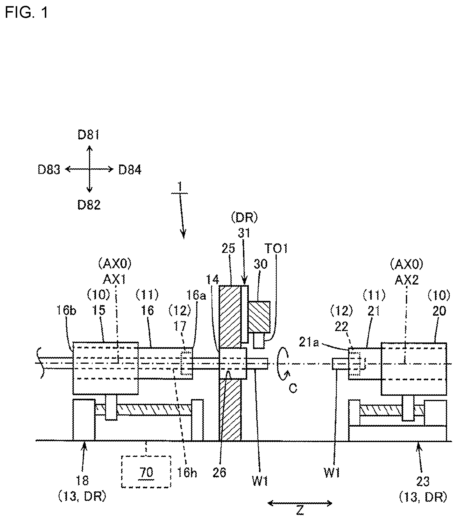
is a front view schematically showing an exemplary configuration of a machine tool.
is a block diagram schematically showing an exemplary configuration of an electrical circuit of the machine tool.
schematically shows an exemplary forming of a tapered eccentric shape on a workpiece.
schematically shows an exemplary movement of a tool in association with rotation of the workpiece on an X-Y plane.
schematically shows an exemplary forming of a tapered eccentric shape on the workpiece around an eccentric axis unparallel to a spindle axis.
schematically shows an exemplary forming of a tapered eccentric shape whose machining start section and machining end section are angled with respect to the X-Y plane.
schematically shows how a relative position of the tool is decided to form the tapered eccentric shape whose machining start section and machining end section are angled with respect to the X-Y plane.
is a flow chart schematically showing an exemplary eccentric shape forming.
is a block diagram of a modified embodiment schematically showing an exemplary configuration of an electrical circuit of the machine tool.
DETAILED DESCRIPTION
Hereinafter, an embodiment of the present invention will be described referring to the drawings. The invention is not limited to the exemplary embodiments. The features disclosed herein are not necessarily essential to the invention.
(1) Summary of Technology in Scope of the Invention
Technology of the invention is being described with reference to to . The drawings only schematically show an example of the invention. They may have a mismatch to each other due to different magnification in each direction. Each element of the technology is not limited to the element denoted by a symbol in the embodiment.
Embodiment 1
As shown in and , a machine tool (for example, a lathe 1 ) of an embodiment of the invention may include a spindle 11 , a tool post 30 , a driving unit DR, and a controller (for example, an NC apparatus 70 ). The spindle 11 holding a workpiece W 1 may rotate around a spindle axis AX 0 . A tool TO 1 may be attached to the tool post 30 to be available to machine the workpiece W 1 . The driving unit DR may vary a positional relationship between the spindle 11 and the tool post 30 . The controller ( 70 ) may control the driving unit DR to vary the positional relationship between the spindle 11 and the tool post 30 to thereby form an eccentric shape (for example, a protrusion W 1 p ) on the workpiece W 1 around an eccentric axis AX 3 deviating from the spindle axis AX 0 as shown in to . The controller ( 70 ) may acquire a coordinate of a first machining start point SpA of the eccentric shape (W 1 p ) in a reference phase (for example, θ=0°) of the workpiece W 1 around the spindle axis AX 0 , a coordinate of a second machining start point SpB of the eccentric shape (W 1 p ) in an anti-phase (for example, θ=180°) different from the reference phase by 180 degrees, a coordinate of a first machining end point EpA of the eccentric shape (W 1 p ) in the reference phase (for example, θ=0°), and a coordinate of a second machining end point EpB of the eccentric shape (W 1 p ) in the anti-phase (for example, θ=180°). The controller ( 70 ) may decide a moving path (for example, an imaginary circle C 1 ) of the tool TO 1 in association with rotation of the workpiece W 1 at least according to the coordinates of the first start point SpA, the second start point SpB, the first end point EpA, and the second end point EpB. The controller ( 70 ) may thereby control forming the eccentric shape (W 1 p ) around the eccentric axis AX 3 passing both a start point origin SpO and an end point origin EpO. The start point origin SpO may be a middle point between the first start point SpA and the second start point SpB. The end point origin EpO may be a middle point between the first end point EpA and the second end point EpB. The controller ( 70 ) may control movement of the tool TO 1 along the moving path (C 1 ) in association with rotation of the workpiece W 1 .
The distance between the first start point SpA and the second start point SpB may be different from the distance between the first end point EpA and the second end point EpB on the X-Y plane perpendicular to the spindle axis AX 0 to form the tapered eccentric shape (W 1 p ) on the workpiece W 1 . X and Y coordinates of the start point origin SpO may be different from X and Y coordinates of the end point origin EpO to form the eccentric shape (W 1 p ) around the eccentric axis AX 3 unparallel to the spindle axis AX 0 . The eccentric shape (W 1 p ) formed on the workpiece W 1 in the embodiment may have variety in addition to the conventional eccentric shape of a constant radius around the axis parallel to the spindle axis AX 0 . The embodiment can provide a machine tool capable of improving freedom in eccentric shape forming.
The driving unit may drive the tool post to vary the positional relationship between the spindle and the tool post. The driving unit may drive the spindle to vary the positional relationship between the spindle and the tool post. The driving unit may drive both the tool post and the spindle to vary the positional relationship between the spindle and the tool post. The eccentric shape may include any shape including a protrusion and a hole. The controller may acquire one or more parameters in addition to the coordinates of the four points (SpA, SpB, EpA, EpB). The parameter may include a feed pitch of the workpiece in a Z-axis direction along the spindle axis, a spindle rotation angle as a unit for deciding the tool moving path, and a circumferential speed of the rotating workpiece. The controller may decide the tool moving path according to the coordinates of the four points (SpA, SpB, EpA, EpB) and one or more other parameters. The words “first” and “second” only identify each of plural similar elements and does not mean any order of the plural similar elements. The remarks may apply to the following embodiments.
Embodiment 2
As shown in to , the controller ( 70 ) may calculate a diameter (SpD) of the eccentric shape (W 1 p ) in a direction perpendicular to the spindle axis AX 0 according to the coordinates of the first start point SpA and the second start point SpB. The controller ( 70 ) may calculate a diameter (EpD) of the eccentric shape (W 1 p ) in a direction perpendicular to the spindle axis AX 0 according to the coordinates of the first end point EpA and the second end point EpB. The controller ( 70 ) may interpolate a diameter (WpD) of the eccentric shape (W 1 p ) at a halfway point origin WpO according to the diameter (SpD) and the diameter (EpD). The halfway point origin WpO may be a middle point between the start point origin SpO and the end point origin EpO on the eccentric axis AX 3 . The controller ( 70 ) may decide the moving path of the tool TO 1 along the circumference of an imaginary circular arc (C 1 ) around a circular arc center WpC deviating from the spindle axis AX 0 according to the diameter (WpD).
The diameter (SpD) of the eccentric shape (W 1 p ) at a machining start section thereof may be different from the diameter (EpD) of the eccentric shape (W 1 p ) at a machining end section thereof to form the tapered eccentric shape (W 1 p ) on the workpiece W 1 . The embodiment can provide a machine tool capable of improving freedom in eccentric shape forming. The imaginary circular arc may conceptually include an imaginary circle assuming the spindle rotation angle of 360 degrees. The circumference of the imaginary circular arc may conceptually include a circumference of the imaginary circle. The above remarks may be applied to the following embodiments.
Embodiment 3
As shown in to , the controller ( 70 ) may calculate an eccentric amount (SpE) of the start point origin SpO deviating from the spindle axis AX 0 according to the coordinates of the first start point SpA and the second start point SpB. The controller ( 70 ) may calculate an eccentric amount (EpE) of the end point origin EpO deviating from the spindle axis AX 0 according to the coordinates of the first end point EpA and the second end point EpB. The controller ( 70 ) may interpolate an eccentric amount (WpE) of the halfway point origin WpO according to the eccentric amount (SpE) and the eccentric amount (EpE). The halfway point origin WpO may be the middle point between the start point origin SpO and the end point origin EpO on the eccentric axis AX 3 . The controller ( 70 ) may decide the moving path of the tool TO 1 along the circumference of the imaginary circular arc (C 1 ) of a size corresponding to the eccentric amount (WpE).
The eccentric amount (SpE) of the start point origin SpO may be different from the eccentric amount (EpE) of the end point origin EpO to form the eccentric shape (W 1 p ) around the eccentric axis AX 3 unparallel to the spindle axis AX 0 . The embodiment can provide a machine tool capable of improving freedom in eccentric shape forming.
Embodiment 4
The coordinates of the first start point SpA, the second start point SpB, the first end point EpA, and the second end point EpB may respectively include Z-coordinates, which is a coordinate on the Z-axis along the spindle axis AX 0 . As shown in , on a first outline connecting the first start point SpA and the first end point EpA (for example, on a first line segment SpA-EpA), the controller ( 70 ) may control the driving unit DR to vary the positional relationship between the spindle 11 and the tool post 30 with respect to the Z-axis each time the workpiece W 1 rotates on the spindle axis AX 0 by an amount obtained by dividing the difference of the Z-coordinates between the first start point SpA and the first end point EpA (for example, a moving amount ZdA) by the number of divisions N. On a second outline connecting the second start point SpB and the second end point EpB (for example, on a second line segment SpB-EpB), the controller ( 70 ) may control the driving unit DR to vary the positional relationship between the spindle 11 and the tool post 30 with respect to the Z-axis each time the workpiece W 1 rotates on the spindle axis AX 0 by an amount obtained by dividing the difference of the Z-coordinates between the second start point SpB and the second end point EpB (for example, a moving amount ZdB) by the number of divisions N. For example, as shown in , on the first line segment SpA-EpA, the controller ( 70 ) may control the driving unit DR to vary the positional relationship between the spindle 11 and the tool post 30 with respect to the Z-axis each time the workpiece W 1 rotates on the spindle axis AX 0 by an amount obtained by dividing the length of the first line segment SpA-EpA by the number of divisions N. On the second line segment SpB-EpB, the controller ( 70 ) may control the driving unit DR to vary the positional relationship between the spindle 11 and the tool post 30 with respect to the Z-axis each time the workpiece W 1 rotates on the spindle axis AX 0 by an amount obtained by dividing the length of the second line segment SpB-EpB by the number of divisions N.
The difference of the Z-coordinates between the first start point SpA and the first end point EpA may be different from the difference of the Z-coordinates between the second start point SpB and the second end point EpB to form the eccentric shape (W 1 p ) on the workpiece W 1 . The embodiment can provide a machine tool capable of improving freedom in eccentric shape forming. The first outline and the second outline may include a straight line and a curved line. The remarks may be applied to the following embodiments.
Embodiment 5
As shown in and , the driving unit DR may include a tool post driver 31 capable of moving the tool post 30 along an X-axis and a Y-axis perpendicular to each other and perpendicular to the Z-axis, and a headstock driver 13 capable of moving the spindle 11 along the Z-axis. The controller ( 70 ) may control movement of the tool TO 1 in association with rotation of the workpiece W 1 along the X-axis and the Y-axis and control vibration of the workpiece W 1 in association with rotation of the workpiece W 1 along the Z-axis to thereby vibrate the positional relationship between the spindle 11 and the tool post 30 with respect to the Z-axis in association with rotation of the workpiece W 1 . In a lathe where the tool post 30 does not move along the Z-axis, the controller ( 70 ) may control vibration of the workpiece W 1 in association with rotation of the workpiece W 1 along the Z-axis to form the eccentric shape (W 1 p ) on the workpiece W 1 regardless of a difference of the Z-coordinates between the first start point SpA and the first end point EpA and regardless of a difference of the Z-coordinates between the second start point SpB and the second end point EpB. The embodiment can provide a machine tool capable of improving freedom in eccentric shape forming.
Embodiment 6
The driving unit DR may move the tool post 30 along the X-axis, the Y-axis, and Z-axis as shown in . The controller ( 70 ) may control movement of the tool TO 1 in association with rotation of the workpiece W 1 along the X-axis and the Y-axis and control vibration of the tool TO 1 in association with rotation of the workpiece W 1 along the Z-axis to thereby vibrate the positional relationship between the spindle 11 and the tool post 30 with respect to the Z-axis in association with rotation of the workpiece W 1 . In a lathe where the spindle 11 does not move along the Z-axis, the controller ( 70 ) may control vibration of the tool TO 1 in association with rotation of the workpiece W 1 along the Z-axis to form the eccentric shape (W 1 p ) on the workpiece W 1 regardless of a difference of the Z-coordinates between the first start point SpA and the first end point EpA and regardless of a difference of the Z-coordinates between the second start point SpB and the second end point EpB. The embodiment can provide a machine tool capable of improving freedom in eccentric shape forming.
Embodiment 7
In the machine tool ( 1 ) including the spindle 11 rotatable together with the workpiece W 1 around the spindle axis AX 0 and the tool post 30 holding the tool TO 1 for use to machine the workpiece W 1 and being capable of varying a positional relationship between the spindle 11 and the tool post 30 to form the eccentric shape (W 1 p ) on the workpiece W 1 around the eccentric axis AX 3 deviating from the spindle axis AX 0 , a method of deciding the moving path of the tool TO 1 includes:
(A1) a first proses ST 1 (for example, Step S 102 in ) acquiring the coordinate of the first machining start point SpA of the eccentric shape (W 1 p ) in the reference phase (θ=0°) of the workpiece W 1 around the spindle axis AX 0 , the coordinate of the second machining start point SpB of the eccentric shape (W 1 p ) in the anti-phase (θ=180°) different from the reference phase by 180 degrees, the coordinate of the first machining end point EpA of the eccentric shape (W 1 p ) in the reference phase (θ=0°), and the coordinate of the second machining end point EpB of the eccentric shape (W 1 p ) in the anti-phase (θ=180°), and (A2) a second prosess ST 2 (for example, Steps S 104 to S 112 in ) deciding the moving path (C 1 ) of the tool TO 1 in association with rotation of the workpiece W 1 at least according to the coordinates of the first machining start point SpA, the second machining start point SpB, the first machining end point EpA, and the second machining end point EpB to form the eccentric shape (W 1 p ) around the eccentric axis AX 3 passing the start point origin SpO between the first machining start point SpA and the second machining start point SpB and the end point origin EpO between the first machining end point EpA and the second machining end point EpB.
The eccentric shape (W 1 p ) formed on the workpiece W 1 in the embodiment may have variety in addition to the conventional eccentric shape of a constant radius around the axis parallel to the spindle axis AX 0 . The embodiment can provide a method of deciding the tool moving path capable of improving freedom in eccentric shape forming.
(2) Exemplary Configuration of the Lathe
is a front view schematically showing an exemplary configuration of the lathe 1 , an example of the machine tool. is a block diagram schematically showing an exemplary configuration of an electrical circuit of the lathe 1 . schematically shows an exemplary forming of the protrusion W 1 p on the workpiece W 1 , an example of the tapered eccentric shape. further includes a view of the workpiece W 1 as seen from the side having the protrusion W 1 p . In , a symbol D 81 denotes an upper direction, a symbol D 82 denotes a lower direction, a symbol D 83 denotes a left direction, a symbol D 84 denotes a right direction, all of which may be the directions viewing the lathe 1 in . As shown in and , the lathe 1 may include a control axis such as the X-axis represented by “X”, the Y-axis represented by “Y”, the Z-axis represented by “Z”, and a C-axis represented by “C”. The Z-axis direction may be a horizontal direction along the spindle axis AX 0 around which the workpiece W 1 rotates. An X-axis direction perpendicular to the Z-axis may be either an up and down direction (the upper direction D 81 and the lower direction D 82 ) or an left and right direction (the left direction D 83 and the right direction D 84 ). A Y-axis direction may be a direction perpendicular to both the Z-axis and the X-axis. The C-axis may be a rotation axis around the spindle axis AX 0 . The drawings schematically show examples of the invention for purpose of explanation. Any description on position may include reverse relationship including right and left directions and rotation directions. Coincidence of direction and position may include a deviation from the exact coincidence.
The lathe 1 may include an NC lathe including a headstock 10 provided with the spindle 11 having a chuck 12 , the headstock driver 13 , a supporting bed 25 having a mounting hole 26 for a guide bush 14 , the tool post 30 , the tool post driver 31 , and the NC apparatus 70 . The headstock 10 may include a front headstock 15 and a back headstock 20 , which is also called an opposite headstock. The front headstock 15 may incorporate a front spindle 16 having a chuck 17 such as a collet. The back headstock 20 may incorporate a back spindle 21 having a chuck 22 such as a collet. The front spindle 16 and the back spindle 21 also called an opposite spindle may be collectively referred to as the spindle 11 . The chuck 17 and the chuck 22 may be collectively referred to as the chuck 12 . The headstock driver 13 may include a front headstock driver 18 capable of driving the front headstock 15 along the Z-axis, and a back headstock driver 23 capable of driving the back headstock 20 along at least the Z-axis. The lathe 1 as shown in and may be a lathe of spindle sliding type that the front spindle 16 moves in the Z-axis direction. The headstock driver 13 and the tool post driver 31 may be an example of the driving unit DR capable of varying the positional relationship between the spindle 11 and the tool post 30 . The NC apparatus 70 may be an example of the controller capable of controlling the positional relationship between the spindle 11 and the tool post 30
The front spindle 16 may releasably hold the bar workpiece W 1 that a bar feeder 8 ( ) may insert from the back. The front spindle 16 holding the workpiece W 1 may be rotatable around a spindle axis AX 1 . A front end 16 a of the front spindle 16 may face the back spindle 21 while a back end 16 b thereof may face the bar feeder 8 . The front spindle 16 may have a through-hole 16 h extended along the spindle axis AX 1 . The workpiece W 1 may be inserted into the through-hole 16 a from the back. A short bar material may be supplied to the chuck 17 from the front end 16 a of the front spindle 16 . The NC apparatus 70 may actuate a front spindle rotation driver 16 c ( ) to rotate the front spindle 16 around the spindle axis AX 1 . The NC apparatus 70 may drive a chuck actuator 17 a ( ) to control the operation of the chuck 17 . The chuck 17 may include a collet. The front headstock driver 18 may drive the front headstock 15 in the Z-axis direction in accordance with a command from the NC apparatus 70 , thereby moving the workpiece W 1 held by the front spindle 16 in the Z-axis direction. The workpiece W 1 may be a long solid columnar material or a long hollow cylindrical material.
A front end 21 a of the back spindle 21 may face the front end 16 a of the front spindle 16 . The back spindle 21 may releasably hold the workpiece W 1 with the chuck 22 where the workpiece W 1 may be an unfinished workpiece protruded from the front end 16 a of the front spindle 16 . The back spindle 21 holding the workpiece W 1 may be rotatable on a spindle axis AX 2 . The NC apparatus 70 may actuate a back spindle rotation driver 21 c ( ) to rotate the back spindle 21 around the spindle axis AX 2 . The NC apparatus 70 may drive a chuck actuator 22 a ( ) to control the operation of the chuck 22 . The chuck 22 may include a collet. The back headstock driver 23 may move the back headstock 20 in the Z-axis direction and further in the X-axis direction or the Y-axis direction in accordance with a command from the NC apparatus 70 . The workpiece W 1 may be held by both the front spindle 16 and the back spindle 21 . The spindle axis AX 2 may coincide with the spindle axis AX 1 . The spindle axis AX 1 and the spindle axis AX 2 may be collectively referred to as the spindle axis AX 0 . A forward direction of the front spindle 16 may be a direction that the workpiece W 1 is pushed out from the front spindle 16 , which is the right direction D 84 in . A backward direction of the front spindle 16 may be a direction toward the bar feeder 8 , which is the left direction D 83 in . A forward direction of the back spindle 21 may be a direction toward the front spindle 16 , which is the left direction D 83 in .
The supporting bed 25 may be located between the front headstock 15 and the back headstock 20 with respect to the Z-axis direction. The supporting bed 25 may have the mounting hole 26 penetrated in the Z-axis direction. The guide bush 14 may be inserted in the mounting hole 26 to be removably attached to the supporting bed 25 as shown in . The guide bush 14 may slidably support the workpiece W 1 protruded forward from the through-hole 16 h of the front spindle 16 . The workpiece W 1 supported by the guide bush 14 may slide in the Z-axis direction. A portion of the workpiece W 1 protruded from the guide bush 14 toward the back spindle 21 (in the right direction D 84 ) may be machined with the tool TO 1 .
The plural tools TO 1 for use to machine the workpiece W 1 held by at least one of the front spindle 16 and the back spindle 21 may be attached to the tool post 30 . The plural tools TO 1 may include a turning tool such as a cut-off tool and a rotary tool such as a drill and an endmill. The NC apparatus 70 may control forming an eccentric shape on the workpiece W 1 with the turning tool as described later. The tool post 30 may include a gang tool post and a turret tool post. As shown in , the tool post driver 31 may include an X-axis driver 32 and a Y-axis driver 33 . The X-axis driver 32 may move the tool post 30 along the X-axis in accordance with a command from the NC apparatus 70 . The Y-axis driver 33 may move the tool post 30 along the Y-axis in accordance with a command from the NC apparatus 70 . The tool TO 1 may move on the X-Y plane along the X-axis and the Y-axis. The NC apparatus 70 may first control machining the front side of the workpiece W 1 held by the front spindle 16 with the tool TO 1 . The NC apparatus 70 may then control cutting off the workpiece W 1 held by both the front spindle 16 and the back spindle 21 with the cut-off tool. The NC apparatus 70 may then control machining the back side of the workpiece W 1 held by the back spindle 21 with the tool TO 1 to thereby form a product of the workpiece W 1 . The lathe 1 may be further provided with another tool post (not shown) such as a tool post specially for back side machining use.
As shown in , the NC apparatus 70 may connect to the bar feeder 8 , an operation unit 80 , the front headstock driver 18 , the front spindle rotation driver 16 c , the chuck actuator 17 a , the back headstock driver 23 , the back spindle rotation driver 21 c , the chuck actuator 22 a , the X-axis driver 32 , and the Y-axis driver 33 . The front headstock driver 18 , the back headstock driver 23 , the X-axis driver 32 , and the Y-axis driver 33 may respectively include not-shown servo motors (built-in motors, for example) and servo amplifiers to vary the positional relationship between the spindle 11 and the tool post 30 in accordance with a command from the NC apparatus 70 . The front spindle rotation driver 16 c and the back spindle rotation driver 21 c may respectively include not-shown servo motors (built-in motors, for example) and servo amplifiers to rotate the spindle 11 around the spindle axis AX 0 in accordance with a command from the NC apparatus 70 . The NC apparatus 70 may control the rotation angle of the workpiece W 1 (a C-axis angle θ) by controlling the front spindle rotation driver 16 c and the back spindle rotation driver 21 c . The chuck actuator 17 a may drive the chuck 17 of the front spindle 16 . The chuck actuator 22 a may drive the chuck 22 of the back spindle 21 . The NC apparatus 70 may include a CPU (Central Processing Unit) 71 , a ROM (Read Only Memory) 72 or a semiconductor memory, a RAM (Random Access Memory) 73 or a semiconductor memory, a timer circuit 74 , and an I/F (Interface) 75 . In , the IF 75 may collectively represent plural interfaces of the bar feeder 8 , the operation unit 80 , the front headstock driver 18 , the front spindle rotation driver 16 c , the chuck actuator 17 a , the back headstock driver 23 , the back spindle rotation driver 21 c , the chuck actuator 22 a , the X-axis driver 32 , and the Y-axis driver 33 . The ROM 72 may store a control program PR 1 for interpreting and executing a machining program PR 2 . The ROM 72 may be a rewritable semiconductor memory. The RAM 73 may rewritably store the machining program PR 2 written by an operator. The machining program may be also called an NC program. The CPU 71 may use the RAM 73 as a work area to execute the control program PR 1 stored in the ROM 72 to enable the NC apparatus 70 to operate accordingly.
The operation unit 80 may include an input 81 and a display 82 to serve as a user interface for the NC apparatus 70 . The input 81 may include a button and a touch panel accessible by the operator. The display 82 may include a monitor that displays various information relating to the lathe 1 including the settings given by the operator. The operator can store the machining program PR 2 in the RAM 73 by using the operation unit 80 and an external computer (not shown).
The NC apparatus 70 may drive the driving unit DR to control the positional relationship between the spindle 11 and the tool post 30 to form the protrusion W 1 p or the eccentric shape ( ) on the workpiece W 1 with the tool TO 1 or the turning tool. The protrusion W 1 p may be the eccentric shape formed around the eccentric axis AX 3 deviating from the spindle axis AX 0 . In , the spindle 11 holding the workpiece W 1 may be the front spindle 16 or the back spindle 21 . The spindle axis AX 0 may be the spindle axis AX 1 around which the front spindle 16 rotates or the spindle axis AX 2 around which the back spindle 21 rotates. The NC apparatus 70 may receive an input of an eccentric distance and a radius of a desired protrusion to form an eccentric protrusion whose shape is limited to a columnar shape around an eccentric axis parallel to the spindle axis. The invention provides a variety of eccentric shapes including a tapered eccentric protrusion, a protrusion around an eccentric axis unparallel to the spindle axis, and a protrusion whose machining start section and machining end section are angled with respect to the X-Y plane.
The NC apparatus 70 may control forming the protrusion W 1 p on the workpiece W 1 according to the coordinates of the four points of the protrusion W 1 p as shown in , especially the coordinates of the first start point SpA, the second start point SpB, the first end point EpA, and the second end point EpB. The first start point SpA may be a machining start point of the protrusion W 1 p in the reference phase (for example, θ=0°) of the workpiece W 1 around the spindle axis AX 0 . The second start point SpB may be a machining start point of the protrusion W 1 p in the anti-phase (for example, θ=180°) different from the reference phase by 180 degrees. The first end point EpA may be a machining end point of the protrusion W 1 p in the reference phase (for example, θ=0°). The second end point EpB may be a machining end point of the protrusion W 1 p in the anti-phase (for example, θ=180°).
The NC apparatus 70 may set the start point origin SpO between the first start point SpA and the second start point SpB. The NC apparatus 70 may set the end point origin EpO between the first end point EpA and the second end point EpB. The start point origin SpO may be favorably a middle point of the line segment SpA-SpB connecting the first start point SpA and the second start point SpB. The end point origin EpO may be favorably a middle point of the line segment EpA-EpB connecting the first end point EpA and the second end point EpB. The NC apparatus 70 may decide a moving path of a tool edge TOt of the tool TO 1 in association with rotation of the workpiece W 1 at least according to the coordinates of the first start point SpA, the second start point SpB, the first end point EpA, and the second end point EpB to form the protrusion W 1 p around the eccentric axis AX 3 passing the start point origin SpO and the end point origin EpO. The NC apparatus 70 may control movement of the tool edge TOt along the moving path in association with rotation of the workpiece W 1 while moving the workpiece W 1 in the Z-axis direction. The NC apparatus 70 may control movement of the tool edge TOt along the moving path in association with rotation of the workpiece W 1 while varying a relative position of the tool edge TOt with respect to the workpiece W 1 on the Z-axis. The Z-coordinate (a coordinate on the Z-axis) may increase as the workpiece W 1 moves rightward (toward D 84 in ) in the Z-axis direction. The Z-coordinate of the relative position of the tool edge TOt not moving in the Z-axis direction may increase leftward (toward D 83 ). For convenience of explanation, the Z-coordinate of the workpiece W 1 corresponding to the tool edge TOt may be explained as the Z-coordinate of the position of the tool edge TOt on the protrusion W 1 p . As described above, the NC apparatus 70 may control vibration of the workpiece W 1 in association with rotation of the workpiece W 1 along the Z-axis as required.
The NC apparatus 70 may set the halfway point origin WpO between the start point origin SpO and the end point origin EpO on the eccentric axis AX 3 according to the Z-coordinate of the position of the tool edge TOt on the protrusion W 1 p . The NC apparatus 70 may calculate the eccentric amount (WpE) of the halfway point origin WpO deviating from the spindle axis AX 0 and the diameter (WpD) of the protrusion W 1 p at the halfway point origin WpO (WpD>0) according to the coordinates of the four points (SpA, SpB, EpA, EpB). If the eccentric axis AX 3 is parallel to the spindle axis AX 0 as shown in , the eccentric amount (WpE) of the halfway point origin WpO may be equal to the eccentric amount (SpE) of the start point origin SpO deviating from the spindle axis AX 0 and to the eccentric amount (EpE) of the end point origin EpO deviating from the spindle axis AX 0 .
(3) Exemplary Tool Moving Path Around the Halfway Point Origin WpO
schematically shows an exemplary movement of the tool TO 1 in association with rotation of the workpiece on the X-Y plane containing the halfway point origin WpO according to the eccentric amount WpE of the halfway point origin WpO and the diameter WpD of the protrusion W 1 p at the halfway point origin WpO. The tool edge TOt may stay at the largest X-coordinate when the C-axis angle θ is 0 degree (θ=0°). The X-coordinate (a coordinate on the X-axis) may be larger in a +X direction and smaller in a −X direction. The Y-coordinate (a coordinate on the Y-axis) may be larger in a +Y direction and smaller in a −Y direction.
When the C-axis angle θ is 0 degree (θ=0°), the tool edge TOt of the tool TO 1 on the X-Y plane may be in a position whose X-coordinate may be obtained by adding the eccentric amount WpE to the radius (WpD/2) of the protrusion W 1 p . When the C-axis angle θ is 180 degrees (θ=180°), the tool edge TOt on the X-Y plane may be in a position whose X-coordinate may be obtained by subtracting the eccentric amount WpE from the radius (WpD/2) of the protrusion W 1 p . In , the radius of the protrusion W 1 p is larger than the eccentric amount WpE (WpD/2>WpE). The tool edge TOt is therefore in a position in the +X direction with respect to the spindle axis AX 0 . If the radius of the protrusion W 1 p is smaller than the eccentric amount WpE (WpD/2<WpE), the tool edge TOt may be in a position in the −X direction with respect to the spindle axis AX 0 .
The tool edge TOt may make a single rotation in a rotation direction R 2 along the circumference of the imaginary circle C 1 whose diameter is equal to a line segment connecting the 0° position at θ=0° and the 180° position at θ=180° while the workpiece W 1 makes a single rotation around the spindle axis AX 0 in a rotation direction R 1 . The imaginary circle C 1 may be conceptually included in the imaginary circular arc. The circumference of the imaginary circle C 1 may be conceptually included in the circumference of the imaginary circular arc. An X-coordinate WpRc of the center (the circular arc center WpC) of the imaginary circle C 1 may be a middle point of the line segment connecting the 0° position and the 180° position, which corresponds to the radius (WpD/2) of the protrusion W 1 p . The radius (a circular arc radius WpRr) of the imaginary circle C 1 may be equal to the eccentric amount WpE of the halfway point origin WpO deviating from the spindle axis AX 0 . As shown in , the tool edge TOt may move along the circumference of the imaginary circle C 1 while the C-axis angle θ changes from 0° to 90°, from 90° to 180°, from 180° to 270°, and from 270° to 0°. The tool TO 1 may thereby form the outline of the protrusion W 1 p on the X-Y plane containing the halfway point origin WpO.
(4) Varying the Positional Relationship Between the Spindle and the Tool Post
The NC apparatus 70 can control forming various eccentric shapes as shown in , 5 , and 6 by acquiring the coordinates of the four points (SpA, SpB, EpA, EpB). The coordinates may include x, y, and z coordinates respectively representing the X-coordinate, the Y-coordinate, and the Z-coordinate of the points. The first start point SpA may have x, y, and z coordinates (SpAx, SpAy, SpAz). The second start point SpB may have x, y, and z coordinates (SpBx, SpBy, SpBz). The first end point EpA may have x, y, and z coordinates (EpAx, EpAy, EpAz). The second end point EpB may have x, y, and z coordinates (EpBx, EpBy, EpBz). The value of the Z-coordinate may become larger as the workpiece W 1 moves rightward in the D 84 direction. The Z-coordinate of the first end point may be larger than that of the first start point (EpAz>SpAz). The Z-coordinate of the second end point may be larger than that of the second start point (EpBz>SpBz). If the eccentric axis AX 3 deviates from the spindle axis AX 0 in the X-axis direction, the Y-coordinates of the first start point, the second start point, the first end point, and the second end point may be equal to zero (SpAy=SpBy=EpAy=EpBy=0). Then, the NC apparatus 70 may acquire the coordinates of the four points (SpA, SpB, EpA, EpB). Instead, the Y-coordinate (SpAy, SpBy, EpAy, EpBy) may be equal to any value but zero. Then, the NC apparatus can control forming the protrusion W 1 p on the workpiece W 1 with the eccentric axis AX 3 offset in the Y-axis direction.
In , the Z-coordinate of the first start point may be equal to that of the second start point (SpAz=SpBz). The Z-coordinate of the first end point may be equal to that of the second end point (EpAz=EpBz). The Z-coordinates of the start point may be smaller than those of the end point (SpAz=SpBz)<(EpAz=EpBz). The X-coordinate of the start point origin SpO may be obtained by: SpOx=(SpAx+SpBx)/2. The Y-coordinate of the start point origin SpO may be equal to zero (SpOy=0). The Z-coordinate of the start point origin SpO may be equal to that of the first start point and that of the second start point (SpOz=SpAz=SpBz). Accordingly, the eccentric amount SpE of the start point origin SpO may be equal to: SpOx=(SpAx+SpBx)/2. The diameter SpD of the protrusion W 1 p may be equal to: |SpAx−SpBx|. The protrusion W 1 p may have the machining start section passing the first start point SpA and the second start point SpB around the eccentric axis AX 3 . The X-coordinate of the end point origin EpO may be obtained by: EpOx=(EpAx+EpBx)/2. The Y-coordinate of the end point origin EpO may be equal to zero (EpOy=0). The Z-coordinate of the end point origin EpO may be equal to that of the first end point and that of the second end point (EpOz=EpAz=EpBz). Accordingly, the eccentric amount EpE of the end point origin EpO may be equal to: EpOx=(EpAx+EpBx)/2. The diameter EpD of the protrusion W 1 p may be equal to: |EpAx−EpBx|. In , the X-coordinate of the start point origin SpO may be equal to that of the end point origin EpO (SpOx=EpOx). The protrusion W 1 p may have the machining end section passing the first end point EpA and the second end point EpB around the eccentric axis AX 3 . The moving amount ZdA from the first start point SpA to the first end point EpA in the Z-axis direction may be obtained by: EpAz−SpAz. The moving amount ZdB from the second start point SpB to the second end point EpB in the Z-axis direction may be obtained by: EpBz−SpBz. In , the moving amount ZdA may be equal to the moving amount ZdB. A Z-axis feed pitch (Zpt) for a single rotation of the workpiece W 1 may be obtained by: ZdA/RevC=ZdB/RevC where RevC (RevC>1) represents the number of revolutions of the workpiece W 1 from the machining start section to the machining end section. The unit of the Z-axis feed pitch Zpt may be mm/rev.
The halfway point origin WpO may have x, y, and z ordinates (WpOx, WpOy, WpOz). The workpiece W 1 may make a first rotation (n=0) at the start point origin SpO and a second rotation (n=1) at the halfway point origin WpO (0≤n<RevC). The halfway point origin WpO may gradually approach the end point origin EpO as the workpiece W 1 rotates. The X-coordinate WpOx of the halfway point origin WpO may be equal to the eccentric amount WpE of the halfway point origin WpO, the eccentric amount SpE of the start point origin SpO, and the eccentric amount EpE of the end point origin EpO. The Y-coordinate WpOy of the halfway point origin WpO may be equal to zero. When the C-axis angle θ is 0 degree (θ=0°), the Z-coordinate WpOz of the halfway point origin WpO may be obtained by: WpOz=SpAz +{( n /Rev C )× ZdA} (1) When the C-axis angle θ is 0 degree (θ=0°), the diameter WpD of the protrusion W 1 p at the halfway point origin WpO may be obtained by: WpD=SpD +{( n /Rev C )×( EpD−SpD )} (2) The NC apparatus 70 may control interpolating the diameter WpD of the protrusion W 1 p at the halfway point origin WpO according to the diameter SpD at the start point origin SpO and the diameter EpD at the end point origin EpO.
As described referring to , the moving path of the tool edge TOt may extend along the circumference of the imaginary circle C 1 according to the Z-coordinate of the position of the tool edge TOt on the protrusion W 1 p . The X-coordinate WpRc of the center (the circular arc center WpC) of the imaginary circle C 1 may be equal to the radius (WpD/2) of the protrusion W 1 p according to the Z-coordinate WpOz of the halfway point origin WpO. An X-coordinate (SpRc) of the circular arc center WpC at the Z-coordinate (SpOz=SpAz=SpBz) of the start point origin SpO may be equal to the radius (SpD/2) of the machining start section. An X-coordinate (EpRc) of the circular arc center WpC at the Z-coordinate (EpOz=EpAz=EpBz) of the end point origin EpO may be equal to the radius (EpD/2) of the machining end section.
The radius (the circular arc radius WpRr) of the imaginary circle C 1 may be equal to the eccentric amount WpE of the halfway point origin WpO deviating from the spindle axis AX 0 . A circular arc radius (SpRr) at the Z-coordinate SpOz of the start point origin SpO may be equal to the eccentric amount SpE of the start point origin SpO deviating from the spindle axis AX 0 . A circular arc radius (EpRr) at the Z-coordinate EpOz of the end point origin EpO may be equal to the eccentric amount EpE of the end point origin EpO deviating from the spindle axis AX 0 . The NC apparatus 70 may control movement of the tool edge TOt in association with rotation of the workpiece W 1 along the circumference of the imaginary circle C 1 on the X-Y plane containing the halfway point origin WpO. The imaginary circle C 1 may have the circular arc radius WpRr around the circular arc center WpC whose X-coordinate WpRc depends on the Z-coordinate WpOz of the halfway point origin WpO. The NC apparatus 70 may thereby decide the moving path of the tool TO 1 along the circumference of the imaginary circle C 1 around the circular arc center WpC offset from the spindle axis AX 0 according to the diameter WpD at the halfway point origin WpO. The NC apparatus 70 may control movement of the tool edge TOt in association with rotation of the workpiece W 1 along the circumference of the imaginary circle C 1 having the circular arc radius WpRr around the circular arc center WpC according to movement of the workpiece W 1 in the Z-axis direction. The NC apparatus 70 may thereby control forming the tapered protrusion W 1 p on the workpiece W 1 around the eccentric axis AX 3 .
The X and Y coordinates of the tool edge TOt may be calculated in rotation angle unit (resolution Reso) less than a single rotation of the workpiece W 1 . The resolution Reso may be the C-axis angle larger than 0° and smaller than 360°. The Z-coordinate of the circular arc center WpC may be equal to the Z-coordinate WpOz of the halfway point origin WpO, which may vary by (ZdA/RevC) per every rotation of the workpiece W 1 . The Z-coordinate of the circular arc center WpC may vary by (θ/360)×(ZdA/RevC) when the workpiece W 1 rotates at the C-axis angle θ. The Z-coordinate WpOz of the halfway point origin WpO, which is the Z-coordinate of the circular arc center WpC, may be obtained by:
WpOz = SpAz + { ( n / RevC ) × ZdA } + { ( θ / 360 ) × ( ZdA / RevC ) } = SpAz + { n ′ × ( ZdA / RevC ) } ( 3 ) where the number of times of rotation (n′) may be the value obtained by adding (θ/360) to the number of times of rotation (n). The diameter WpD of the protrusion W 1 p at the halfway point origin WpO may be obtained by: WpD=SpD +{( n ′/Rev C )×( EpD−SpD )} (4) As described above, the X-coordinate WpRc of the circular arc center WpC may be equal to the radius (WpD/2) of the protrusion W 1 p . The circular arc radius WpRr may be equal to the eccentric amount WpE.
The NC apparatus 70 may calculate the X-coordinate WpRc of the circular arc center WpC and the circular arc radius WpRr in rotation angle unit (resolution Reso). The NC apparatus 70 may control movement of the tool edge TOt in association with rotation of the workpiece W 1 along the circumference of the imaginary circular arc (the imaginary circle C 1 ) having the circular arc radius WpRr around the circular arc center WpC whose X-coordinate WpRc depends on the Z-coordinate WpOz of the halfway point origin WpO. The NC apparatus 70 may thereby control forming the protrusion W 1 p on the workpiece W 1 around the eccentric axis AX 3 .
schematically shows an exemplary forming of the tapered eccentric protrusion W 1 p on the workpiece W 1 around the eccentric axis AX 3 unparallel to the spindle axis AX 0 . further includes a view of the workpiece W 1 as seen from the side having the protrusion W 1 p . The Z-coordinate of the first start point may be equal to that of the second start point (SpAz=SpBz). The Z-coordinate of the first end point may be equal to that of the second end point (EpAz=EpBz). The Z-coordinates of the start points may be smaller than those of the end points (SpAz=SpBz)<(EpAz=EpBz). The X-coordinate of the start point origin SpO may be obtained by: SpOx=(SpAx+SpBx)/2. The Y-coordinate of the start point origin SpO may be equal to zero (SpOy=0). The Z-coordinate of the start point origin SpO may be equal to that of the first start point and that of the second start point (SpOz=SpAz=SpBz). Accordingly, the eccentric amount SpE of the start point origin SpO may be equal to: SpOx=(SpAx+SpBx)/2. The diameter SpD of the protrusion W 1 p at the machining start section may be equal to: |SpAx−SpBx|. The X-coordinate of the end point origin EpO may be obtained by: EpOx=(EpAx+EpBx)/2. The Y-coordinate of the end point origin EpO may be equal to zero (EpOy=0). The Z-coordinate of the end point origin EpO may be equal to that of the first end point and that of the second end point (EpOz=EpAz=EpBz). Accordingly, the eccentric amount EpE of the end point origin EpO may be equal to: EpOx=(EpAx+EpBx)/2. The diameter EpD of the protrusion W 1 p at the machining end section may be equal to: |EpAx−EpBx|. In , the X-coordinate of the start point origin SpO may be larger than that of the end point origin EpO (SpOx>EpOx).
The Z-coordinate WpOz of the halfway point origin WpO may be obtained by the formula (1) or (3) as above described. When the C-axis angle θ is 0 degree (θ=0°), the eccentric amount WpE of the halfway point origin WpO may be obtained by: WpE=SpE +{( n /Rev C )×( EpE−SpE )} (5) When the C-axis angle θ is not 0 degree (θ=0°), the eccentric amount WpE of the halfway point origin WpO may be obtained by: WpE=SpE +{( n ′/Rev C )×( EpE−SpE )} (6) where (n′) may be a value obtained by adding (θ/360) to the number of times of rotation (n). The NC apparatus 70 may control interpolating the eccentric amount WpE of the halfway point origin WpO deviating from the spindle axis AX 0 according to the eccentric amount SpE of the start point origin SpO and the eccentric amount EpE of the end point origin EpO.
The diameter WpD of the protrusion W 1 p at the halfway point origin WpO may be obtained by the formula (2) or (4) as described above.
As described referring to , the moving path of the tool edge TOt may extend along the circumference of the imaginary circle C 1 according to the Z-coordinate of the position of the tool edge TOt on the protrusion W 1 p . The X-coordinate WpRc of the circular arc center WpC may be equal to the radius (WpD/2) of the protrusion W 1 p according to the Z-coordinate WpOz of the halfway point origin WpO. The circular arc radius WpRr may be equal to the eccentric amount WpE of the halfway point origin WpO deviating from the spindle axis AX 0 . The NC apparatus 70 may control movement of the tool edge TOt in association with rotation of the workpiece W 1 along the circumference of the imaginary circular arc (the imaginary circle C 1 ) on the X-Y plane containing the halfway point origin WpO. The imaginary circular arc may have the circular arc radius WpRr around the circular arc center WpC whose X-coordinate WpRc depends on the Z-coordinate WpOz of the halfway point origin WpO. The NC apparatus 70 may thereby decide the moving path of the tool TO 1 along the circumference of the imaginary circular arc (the imaginary circle C 1 ) of the size according to the eccentric amount WpE. The NC apparatus 70 may control movement of the tool edge TOt in association with rotation of the workpiece W 1 along the circumference of the imaginary circular arc having the circular arc radius WpRr around the circular arc center WpC according to movement of the workpiece W 1 in the Z-axis direction. The NC apparatus 70 may thereby control forming the protrusion W 1 p on the workpiece W 1 around the eccentric axis AX 3 unparallel to the spindle axis AX 0 .
schematically shows an exemplary forming of the tapered eccentric protrusion W 1 p whose machining start section and machining end section are angled with respect to the X-Y plane. further includes a view of the workpiece W 1 as seen from the side having the protrusion W 1 p . The Z-coordinate SpAz of the first start point SpA may be different from the Z-coordinate SpBz of the second start point SpB. The Z-coordinate EpAz of the first end point EpA may be different from the Z-coordinate EpBz of the second end point EpB. The moving amount ZdA in the Z-axis direction from the first start point SpA to the first end point EpA may be different from the moving amount ZdB in the Z-axis direction from the second start point SpB to the second end point EpB. In , the Z-coordinate of the first start point may be larger than that of the second start point (SpAz >SpBz). The Z-coordinate of the first end point may be larger than that of the second end point (EpAz >EpBz). The moving amount ZdB may be larger than the moving amount ZdA (ZdB>ZdA). The X-coordinate of the start point origin SpO may be obtained by: SpOx=(SpAx+SpBx)/2. The Y-coordinate of the start point origin SpO may be equal to zero (SpOy=0). The Z-coordinate of the start point origin SpO may be obtained by: SpOz=(SpAz+SpBz)/2. Accordingly, the eccentric amount SpE of the start point origin SpO may be equal to: SpOx=(SpAx+SpBx)/2. The diameter SpD of the protrusion W 1 p at the machining start section may be equal to: |SpAx−SpBx|. The X-coordinate of the end point origin EpO may be obtained by: EpOx=(EpAx+EpBx)/2. The Y-coordinate of the end point origin EpO may be equal to zero (EpOy=0). The Z-coordinate of the end point origin EpO may be obtained by: EpOz=(EpAz+EpBz)/2. Accordingly, the eccentric amount EpE of the end point origin EpO may be equal to: EpOx=(EpAx+EpBx)/2. The diameter EpD of the protrusion W 1 p at the machining end section may be equal to: |EpAx−EpBx|. The eccentric amount WpE of the halfway point origin WpO may be obtained by the formula (5) or (6) as described above. The diameter WpD of the protrusion W 1 P at the halfway point origin WpO may be obtained by the formula (2) or (4) as described above.
The NC apparatus 70 may necessarily control vibration of the workpiece W 1 along the Z-axis in association with rotation of the workpiece W 1 around the spindle axis AX 0 to form the protrusion W 1 p on the workpiece W 1 as shown in .
schematically shows how the relative position of the tool TO 1 is decided to form the tapered protrusion W 1 p whose machining start section and machining end section are angled with respect to the X-Y plane As shown in , the Z-coordinate of the first line segment SpA-EpA connecting the first start point SpA and the first end point EpA may not match the Z-coordinate of the second line segment SpB-EpB connecting the second start point SpB and the second end point EpB. The first line segment SpA-EpA may consist of plural sections divided by adjacent points. The second line segment SpB-EpB may consist of plural sections divided by adjacent points. The position of the tool edge TOt in a section on the first line segment SpA-EpA may match the position of the tool edge TOt in a section on the second line segment SpB-EpB.
The first line segment SpA-EpA and the second line segment SpB-EpB may be respectively equally divided by the number of divisions N where the number of divisions N may be the number of revolutions RevC of the workpiece W 1 rotating from the machining start section to the machining end section of the protrusion W 1 p . The last section (immediately before the first end point EpA/the second end point EpB) of the first line segment SpA-EpA/the second line segment SpB-EpB may be shorter than the other sections if the number of revolutions RevC is not an integer. In , the first line segment SpA-EpA may have a point “An” where “n” (integer) represents the number of times of rotation. The second line segment SpB-EpB may have a point “Bn” where “n” (integer) represents the number of times of rotation. The first line segment SpA-EpA may further have a point “An+1” (Zan+1) where n+1 represents the number of times of rotation. The second line segment SpB-EpB may further have a point “Bn+1” (Zbn+1) where n+1 represents the number of times of rotation. The first start point SpA may be referred to as the point A0 where n=0. The second start point SpB may be referred to as the point BO where n=0.
The point An may have x, y, and z coordinates (Xan, Yan, Zan). The point Bn may have x, y, and z coordinates (Xbn, Ybn, Zbn). The Y-coordinate of the point An and the Y-coordinate of the point Bn may be equal to zero (Yan=Ybn=0). The point An may have a projection coordinate (Xan, 0) on the X-Y plane. The point Bn may have a projection coordinate (Xbn, 0) on the X-Y plane. The NC apparatus 70 may control positioning the tool edge TOt at the n times rotation to form the protrusion W 1 p of a circle of a diameter corresponding to the line segment connecting the points (Xan, 0) and (Xbn, 0) on the X-Y plane. The center of the circle on the X-Y plane may be equal to the halfway point origin WpO. The diameter WpD of the circle on the X-Y plane may be obtained by: Xan−Xbn. The NC apparatus 70 may control movement of the tool edge TOt on the X-Y plane along the circumference of the imaginary circle C 1 as defined by the eccentric amount WpE (of the halfway point origin WpO) and the diameter WpD.
The Z-coordinate of the position of the tool edge TOt may have different variation between the first line segment SpA-EpA and the second line segment SpB-EpB. The number of divisions N may depend on whichever line segment having a larger variation in the Z-coordinate among the first line segment SpA-EpA and the second line segment SpB-EpB. The number of divisions N corresponding to the number of revolutions RevC may be obtained by: MAX (ZdA:ZdB)/Zpt where the “MAX (ZdA:ZdB)” may be the moving amount ZdA in the Z-axis direction from the first start point SpA to the first end point EpA or the moving amount ZdB in the Z-axis direction from the second start point SpB to the second end point EpB, whichever is larger, and the “Zpt” may be the Z-axis feed pitch of the workpiece W 1 per every rotation.
The Z-coordinate of the position of the tool edge TOt on the protrusion W 1 p may be a Z-coordinate Zan of the point An at the C-axis angle θ=0° and a Z-coordinate Zbn of the point Bn at the C-axis angle θ=180°. Variation in the Z-coordinate Zac of the position of the tool edge TOt on the first line segment SpA-EpA per every rotation of the workpiece W 1 may be obtained by: Zac=ZdA/RevC. Variation in the Z-coordinate Zbc of the position of the tool edge TOt on the second line segment SpB-EpB per every rotation of the workpiece W 1 may be obtained by: Zbc=ZdB/RevC.
The Z-coordinate Zan of the point An at the n times rotation may be obtained by:
Zan = SpAz + n × Zac = SpAz + n × ( ZdA / RevC ) ( 7 ) The Z-coordinate Zbn of the point Bn at then times rotation may be obtained by:
Zbn = SpBz + n × Zbc = SpBz + n × ( ZdB / RevC ) ( 8 )
A line segment An-Bn connecting the points An and Bn have a middle point corresponding to the halfway point origin WpO. The Z-coordinate of the middle point may be represented by: (Zan+Zbn)/2. Vibration of the workpiece W 1 in the Z-axis direction at the middle point of the line segment An-Bn may be represented by: {(Zan−Zbn)/2}×cos (θ). Accordingly, the Z-coordinate Znc of the position of the tool edge TOt at the C-axis angle θ at the n times rotation may be obtained by: Znc ={( Zan+Zbn )/2}+{( Zan−Zbn )/2}×cos(θ) (9) The NC apparatus 70 may control the Z-coordinate of the workpiece W 1 according to the Z-coordinate Znc calculated by the formula (9) and thereby control vibration of the workpiece W 1 in association with rotation of the workpiece W 1 along the Z-axis. On the first line segment SpA-EpA, the NC apparatus 70 may control movement of the tool edge TOt in association with rotation of the workpiece W 1 along the circumference of the imaginary circle C 1 on the X-Y plane to vary the positional relationship between the spindle 11 and the tool post 30 by an amount obtained by dividing the length of the first line segment SpA-EpA by the number of divisions N. On the second line segment SpB-EpB, the NC apparatus 70 may control movement of the tool edge TOt in association with rotation of the workpiece W 1 along the circumference of the imaginary circle C 1 on the X-Y plane to vary the positional relationship between the spindle 11 and the tool post 30 by an amount obtained by dividing the length of the second line segment SpB-EpB by the number of divisions N.
The X-coordinate and the Y-coordinate of the tool edge TOt may be obtained in rotation angle unit (resolution Reso) smaller than a single rotation of the workpiece W 1 . Moving amount ZdO in the Z-axis direction from the start point origin SpO to the end point origin EpO may be obtained by: ZdO=(ZdA+ZdB)/2. The Z-coordinate of the circular arc center WpC may be equal to the Z-coordinate WpOz of the halfway point origin WpO, which may vary by (ZdO/RevC) per every rotation of the workpiece W 1 . Accordingly, the Z-coordinate of the circular arc center WpC may vary by (θ/360)×(ZdO/RevC) when the workpiece W 1 rotates at the C-axis angle θ. The variation amount (θ/360)×(ZdO/RevC) may be add to the formula (9): Znc ={( Zan+Zbn )/2}+{( Zan−Zbn )/2}×cos(θ)+(θ/360)×( ZdO /Rev C ) (10) The Z-coordinate WpOz of the halfway point origin WpO may be obtained by:
WpOz = SpOz + { ( n / RevC ) × ZdO } + { ( θ / 360 ) × ( ZdO / RevC ) } = SpOz + { n ′ / ( ZdO / RevC ) } ( 11 ) where the number of times of rotation (n′) may be a value obtained by adding (θ/360) to the number of times of rotation (n). The diameter WpD of the protrusion W 1 p projected on the X-Y plane containing the halfway point origin WpO may be obtained by: WpD=SpD +{( n ′/Rev C )×( EpD−SpD )} (12) The X-coordinate WpRc of the circular arc center WpC may be equal to the radius (WpD/2) of the protrusion W 1 p . The circular arc radius WpRr may be equal to the eccentric amount WpE.
The NC apparatus 70 may calculate the Z-coordinate Znc in rotation angle unit (resolution Reso) at the C-axis angle θ at the n times rotation, the X-coordinate WpRc of the circular arc center WpC, and the circular arc radius WpRr. The NC apparatus 70 may control movement of the tool edge TOt in association with rotation of the workpiece W 1 along the circumference of the imaginary circular arc (the imaginary circle C 1 ). The imaginary circular arc may have the circular arc radius WpRr around the circular arc center WpC having the X-coordinate WpRc according to the Z-coordinate WpOz of the halfway point origin WpO on the X-Y plane containing the halfway point origin WpO. The NC apparatus may further control movement of the workpiece W 1 in association with rotation of the workpiece along the Z-axis to locate the workpiece W 1 in the position of the Z-coordinate Znc. As described above, the NC apparatus 70 may control movement of the tool edge TOt in association with rotation of the workpiece W 1 along the circumference of the imaginary circular arc (the imaginary circle C 1 ) and further control vibration of the workpiece W 1 in association with rotation of the workpiece W 1 along the Z-axis to thereby form, on the workpiece W 1 , the tapered protrusion W 1 p whose machining start section and machining end section are angled with respect to the X-Y plane. The NC apparatus 70 can control the positional relationship between the spindle 11 and the tool post 30 even if one of the machining start section and the machining end section extends along the X-Y plane.
(5) Exemplary Eccentric Shape Forming Process
is an exemplary flow chart of eccentric shape forming process to form the protrusion W 1 p on the workpiece W 1 . The NC apparatus 70 in may receive an instruction at the input 81 to display an eccentric shape forming command creating screen to start the eccentric shape forming process. The NC apparatus 70 may execute an eccentric shape forming method including a moving path deciding method. The eccentric shape forming method may include the following processes (A1), (A2), and (A3) processes:
(A1) First Process ST 1 (Step S 102 ): Obtaining the coordinates of the first machining start point SpA and the first machining end point EpA of the protrusion W 1 p in the reference phase (θ=0°) of the workpiece W 1 around the spindle axis AX 0 and the coordinates of the second machining start point SpB and the second machining end point EpB of the protrusion W 1 p in the anti-phase (θ=180°). (A2) Second Process ST 2 (Step S 104 to Step S 112 ): Deciding the moving path (the imaginary circle C) of the tool TO 1 in association with rotation of the workpiece W 1 at least according to the coordinates of the four points (SpA, SpB, EpA, EpB) to thereby form the protrusion W 1 p around the eccentric axis AX 3 passing the start point origin SpO between the first start point SpA and the second start point SpB and the end point origin EpO between the first end point EpA and the second end point EpB. (A3) Third Process ST 3 (Step S 114 ): Moving the tool TO 1 along the moving path (the imaginary circle C 1 ) in association with rotation of the workpiece W 1 .
First, the NC apparatus 70 may obtain the coordinates (x, y, z) of the four points (SpA, SpB, EpA, EpB), the Z-axis feed pitch Zpt, and the C-axis angle θ (resolution Reso) (S 102 ). Specifically, the NC apparatus 70 may obtain the coordinates (x, y, z) of the first start point SpA and the first end point EpA at θ=0° and the coordinates (x, y, z) of the second start point SpB and the second end point EpB at θ=180°. In this embodiment, the eccentric axis AX 3 may deviate from the spindle axis AX 0 in the X-axis direction and the coordinates (x, y, z) of the four points (SpA, SpB, EpA, EpB) may satisfy the requirements: SpAy=SpBy=EpAy=EpBy =0 SpAx>SpBx EpAx>EpBx SpAz<EpAz SpBz<EpBz Instead, the Y-coordinate (SpAy, SpBy, EpAy, EpBy) may be a value other than 0. Then, the eccentric axis AX 3 may deviate in the Y-axis direction. Instead, the X-coordinates (SpAx, SpBx, EpAx, EpBx) may satisfy both (SpAx <SpBx) and (EpAx <EpBx). Then, the reference phase (θ=0°) may be in the −X direction. Instead, the Z-coordinates (SpAz, SpBz, EpAz, EpBz) may satisfy both (SpAz>EpAz) and (SpBz>EpBz). Then, the moving direction of the workpiece W 1 may be reversed.
Obtaining the Z-axis feed pitch Zpt may be skipped if it is pre-stored. Obtaining the C-axis angle θ (resolution Reso) may be skipped if it is pre-stored. The NC apparatus 70 may further obtain a circumferential speed (a speed in the circumferential direction) of the workpiece W 1 with respect to the position of the tool edge TOt in S 102 to control the rotation speed of the workpiece W 1 thereby contributing to the life of the tool TO 1 . Upon at least obtaining the coordinates of the four points (SpA, SpB, EpA, EpB) satisfying the requirements, the NC apparatus 70 may add an eccentric shape forming command to the machining program PR 2 . The eccentric shape forming command may include at least the coordinates of the four points. The eccentric shape forming command may exclude at least one of the Z-axis feed pitch Zpt and the C-axis angle θ (resolution Reso). Upon reading the eccentric shape forming command from the machining program PR 2 , the NC apparatus 70 may acquire at least the coordinates of the four points.
The NC apparatus 70 may calculate the eccentric amount WpE of the halfway point origin WpO according to the eccentric amount SpE of the start point origin SpO and the eccentric amount EpE of the end point origin EpO (S 104 ) expecting the protrusion W 1 p whose machining start section and machining end section are angled with respect to the X-Y plane as shown in . The X-coordinate of the start point origin SpO may be obtained by: SpOx=(SpAx+SpBx)/2. The Y-coordinate of the start point origin SpO may be equal to zero (SpOy=0). The Z-coordinate of the start point origin SpO may be obtained by: SpOz=(SpAz+SpBz)/2. Accordingly, the eccentric amount SpE of the start point origin SpO may be equal to: SpOx=(SpAx+SpBx)/2. The X-coordinate of the end point origin EpO may be obtained by: EpOx=(EpAx+EpBx)/2. The Y-coordinate of the end point origin EpO may be equal to zero (EpOy=0). The Z-coordinate of the end point origin EpO may be obtained by: EpOz=(EpAz+EpBz)/2. Accordingly, the eccentric amount EpE of the end point origin EpO may be equal to: EpOx=(EpAx+EpBx)/2. The Z-coordinate WpOz of the halfway point origin WpO may be obtained by the formula (11). The eccentric amount WpE of the halfway point origin WpO, which may be equal to the X-coordinate WpOx of the halfway point origin WpO, may be obtained by the formula (6).
As described above, the NC apparatus 70 may control interpolating the eccentric amount WpE of the halfway point origin WpO deviating from the spindle axis AX 0 according to the eccentric amount SpE of the start point origin SpO and the eccentric amount EpE of the end point origin EpO.
The NC apparatus 70 may calculate the diameter WpD of the protrusion W 1 p at the halfway point origin WpO according to the diameter SpD of the machining start section and the diameter EpD of the machining end section of the protrusion W 1 p (S 106 ). Assuming the protrusion W 1 p whose machining start section and machining end section are angled with respect to the X-Y plane as shown in and , the diameter WpD of the protrusion W 1 p at the halfway point origin WpO may be obtained by the formula (4). As described above, the NC apparatus 70 may control interpolating the diameter WpD of the protrusion W 1 p at the halfway point origin WpO according to the diameter SpD of the machining start section and the diameter EpD of the machining end section of the protrusion W 1 p.
The NC apparatus 70 may decide the moving path of the tool edge TOt in association with rotation of the workpiece W 1 on the X-Y plane (S 108 ). As described referring to , the moving path of the tool edge TOt may extend along the circumference of the imaginary circular arc (the imaginary circle C 1 ) according to the Z-coordinate of the position of the tool edge TOt on the protrusion W 1 p . The X-coordinate WpRc of the circular arc center WpC may be equal to the radius (WpD/2) of the protrusion W 1 p according to the Z-coordinate WpOz of the halfway point origin WpO. The circular arc radius WpRr may be equal to the eccentric amount WpE of the halfway point origin WpO deviating from the spindle axis AX 0 . The NC apparatus 70 may decide the moving path of the tool edge TOt at C-axis angle θ (resolution Reso) on the X-Y plane along the circumference of the imaginary circular arc (the imaginary circle C 1 ) of the circular arc radius WpRr around the circular arc center WpC corresponding to the X-coordinate WpRc.
The NC apparatus 70 may calculate the Z-coordinate Zan on the first line segment SpA-EpA at the n times rotation and the Z-coordinate Zbn on the second line segment SpB-EpB at the n times rotation (S 110 ). The Z-coordinate Zan at the n times rotation may be obtained by the formula (7). The Z-coordinate Zbn at the n times rotation may be obtained by the formula (8).
The NC apparatus 70 may calculate the Z-coordinate Znc at the C-axis angle θ at then times rotation (S 112 ) by the formula (9) or (10).
The NC apparatus 70 may control movement of the tool TO 1 in association with rotation of the workpiece W 1 along the X-axis and the Y-axis according to the decided imaginary circular arc (the imaginary circle C 1 ) and control vibration of the workpiece W 1 in association with rotation of the workpiece W 1 along the Z-axis according to the Z-coordinate Znc to vibrate the workpiece W 1 with respect to the Z-axis (S 114 ). The NC apparatus 70 may control varying the positional relationship between the spindle 11 and the tool post 30 on the first line segment SpA-EpA each time the workpiece W 1 rotates by an amount obtained by dividing the length of the first line segment SpA-EpA by the number of divisions N. The NC apparatus 70 may control varying the positional relationship between the spindle 11 and the tool post 30 on the second line segment SpB-EpB each time the workpiece W 1 rotates by an amount obtained by dividing the length of the second line segment SpB-EpB by the number of divisions N. Accordingly, the NC apparatus may control forming the protrusion W 1 p on the workpiece W 1 around the eccentric axis AX 3 deviating from the spindle axis AX 0 .
As described above, the protrusion W 1 p on the workpiece W 1 may not be limited to a columnar eccentric shape formed around the axis parallel to the spindle axis. The invention provides a variety of eccentric shapes including the tapered eccentric protrusion as shown in , the tapered eccentric protrusion around the eccentric axis AX 3 unparallel to the spindle axis AX 0 as shown in , and the tapered eccentric protrusion at least one of whose machining start section and machining end section are angled with respect to the X-Y plane as shown in . The embodiment improves freedom in eccentric shape forming.
(6) Modified Embodiments
The invention may be embodied in various modifications. The machine tool of the invention may include a machining center or other machines but the lathe. The lathe 1 may include a lathe of spindle stationary type that the front spindle 16 does not move in the Z-axis direction. The tool post 30 movable in the X-axis and the Y-axis directions may be movable also in the Z-axis direction. The back spindle 21 may hold the workpiece W 1 instead of the front spindle 16 . The tool TO 1 may be favorably a turning tool but may be a stationary tool such as a drill and a rotary tool such as an endmill. The eccentric shape may include a hole opened in a trumpet shape.
The eccentric shape forming process as shown in may be appropriately modified including a change in the order of the steps. For example, S 104 (calculating the eccentric amount WpE) may be replaced by S 106 (calculating the diameter WpD). Calculating the diameter WpD may be replaced by calculating the radius (WpD/2) to decide the moving path of the tool TO 1 . At least part of the steps S 102 to S 112 may be executed by an external computer.
In S 102 , the eccentric shape forming command may exclude part of the coordinates of the four points (SpA, SpB, EpA, EpB) from the parameters. For example, the eccentric shape forming command to form a columnar eccentric shape may exclude the coordinates of one of the first end point EpA and the second end point EpB. If the eccentric shape forming command to form a columnar eccentric shape includes a parameter for the Z-axis length of the shape, the command may exclude the coordinates of both of the first end point EpA and the second end point EpB.
In the eccentric shape as shown in , 5 , 6 , and 7 , the first start point SpA and the first end point EpA are connected by a straight line and the second start point SpB and the second end point EpB are connected by a straight line. Instead, they may be connected by a curved line. The curved first outline connecting the first start point SpA and the first end point EpA may be calculated by a circular arc interpolation. The curved second outline connecting the second start point SpB and the second end point EpB may be calculated by a circular arc interpolation. On the first outline, the NC apparatus 70 may control varying the positional relationship between the spindle 11 and the tool post 30 with respect to the Z-axis by an amount obtained by dividing the moving amount ZdA from the first start point SpA to the first end point EpA by the number of divisions N. On the second outline, the NC apparatus 70 may control varying the positional relationship between the spindle 11 and the tool post 30 with respect to the Z-axis by an amount obtained by dividing the moving amount ZdB from the second start point SpB to the second end point EpB by the number of divisions N. The NC apparatus 70 may control forming the eccentric shape whose first start point SpA and first end point EpA are connected by a curved line and whose second start point SpB and second start point EpB are connected by a curved line.
is a block diagram schematically showing an exemplary configuration of an electrical circuit of the lathe 1 of a spindle stationary type. The lathe 1 in may differ from the lathe 1 in in that the front head stock driver 18 is removed and a Z-axis driver 34 is added to the tool post driver 31 . The Z-axis driver 34 may drive the tool post 30 along the Z-axis in accordance with a command from the NC apparatus 70 . The tool post driver 31 may drive the tool post 30 along the X-axis, the Y-axis, and the Z-axis. The NC apparatus 70 may control movement of the tool TO 1 in association with rotation of the workpiece W 1 along the X-axis and the Y-axis and control vibration of the tool TO 1 in association with rotation of the workpiece W 1 along the Z-axis to vary the positional relationship between the spindle 11 and the tool post 30 with respect to the Z-axis. The NC apparatus 70 may control forming the eccentric shape on the workpiece W 1 in the lathe 1 of spindle stationary type.
(7) Conclusion
As described above, the invention may provide a technology improving freedom in eccentric shape forming in various embodiments. The fundamental functions and effects are available even in a technology only comprising elements of independent claims. The elements described in the embodiments may be replaced to each other and any combination of the elements may be changed in the scope of the invention. Any prior art may be replaced with the element described in the embodiments and any combination of the prior art and the element may be changed in the scope of the invention.
Figures (9)
Citations
This patent cites (13)
- US5713253
- US2018/0369920
- US2021/0121995
- US2021/0382455
- US2023/0244206
- US2024/0377801
- US108367362
- US69933644
- US1028362
- US3913447
- USH04331038
- US2021140819
- USWO2017/086238