Apparatus and Process for Liquefying Gases
Abstract
A liquefier device which may be a retrofit to an air separation plant or utilized as part of a new design. The flow needed for the liquefier comes from an air separation plant running in a maxim oxygen state, in a stable mode. The three gas flows are low pressure oxygen, low pressure nitrogen, and higher pressure nitrogen. All of the flows are found on the side of the main heat exchanger with a temperature of about 37 degrees Fahrenheit. All of the gases put into the liquefier come out as a subcooled liquid, for storage or return to the air separation plant. This new liquefier does not include a front end electrical compressor, and will take a self-produced liquid nitrogen, pump it up to a runnable 420 PSIG pressure, and with the use of turbines, condensers, flash pots, and multi pass heat exchangers. The liquefier will make liquid from a planned amount of any pure gas oxygen or nitrogen an air separation plant can produce.
Claims (13)
1 . A liquefier device for producing liquid oxygen and liquid nitrogen comprising: a plurality of multi pass counter-current flow heat exchangers including a warmer, a pre-heater, a condenser, and an added cooler; a plurality of shell and tube heat exchangers including; a boiler, an oxygen production flash pot, a nitrogen production flash pot, a load control flash pot, and a pump flash pot, wherein a shell side of each of the shell and tube heat exchangers holds a nitrogen bath; a turbine assembly including a plurality of turbine expanders connected in parallel and exiting to a common header, and a plurality of turbine boosters connected in series, each of the turbine boosters having an associated aftercooler; the warmer, pre-heater, boiler, and condenser configured to receive and cool an oxygen gas flow supplied from an oxygen gas inlet line and directing the cooled oxygen gas flow into a tube side of the oxygen production flash pot to produce subcooled liquid oxygen; a first of the turbine boosters connected in series configured to receive a flow of gas nitrogen to be increased in pressure and supplied from a low pressure nitrogen gas inlet line and another line containing nitrogen gas exiting the shell side of one or more of the oxygen production flash pot, nitrogen production flash pot, load control flash pot, and pump flash pot after being increased in temperature in the multi-pass counter current flow heat exchangers; the multi-pass counter-current flow heat exchangers and boiler also configured to cool a combined flow of gas nitrogen supplied from a high pressure nitrogen gas inlet line and a return flow of equal pressure gas nitrogen in a line connecting from an exit of a second to last of the turbine booster aftercoolers, the combined flow of gas nitrogen then being fed into a tube side of the nitrogen production flash pot to produce subcooled liquid nitrogen; the multi-pass counter current flow heat exchangers and boiler also configured to cool a nitrogen gas flow in a line exiting the aftercooler associated with last turbine booster connected in series and then feed the cooled nitrogen gas flow into a tube side of the pump flash pot to produce subcooled liquid nitrogen, at least some of which is then brought up in pressure and directed into the shell side of the boiler at an inlet temperature of within ±5° F. of a boiler running temperature and is boiled to a vapor pressure point, and then is directed into the pre-heater to produce a nitrogen gas stream having a temperature and a pressure to run the turbine expanders; a pressure drop pipeline containing a nitrogen exit flow from the turbine expanders having an exit temperature close to a liquid phase connecting to an inlet to a phase separator in which nitrogen gas and liquid nitrogen droplets in the nitrogen exit flow are separated, and a flow of gas nitrogen off of the phase separator is directed in either a first branch line connecting sequentially through the condenser, boiler, pre heater, and warmer and then connecting to the turbine boosters connected in series between an exit of the second to last turbine booster aftercooler and inlet to the last turbine booster, or in a second branch line connecting to a tube side of the load control flash pot to produce subcooled liquid nitrogen; and another exit line from the phase separator connected to direct separated liquid nitrogen through the added cooler to the shell side of the pump flash pot, or into another line including an overflow valve and connecting to the second branch line from the phase separator.
Show 12 dependent claims
2 . The liquefier device of claim 1 , wherein the turbine assembly includes four turbine expanders connected in parallel and four turbine boosters connected in series.
3 . The liquefier device of claim 1 , wherein the subcooled liquid oxygen produced by the oxygen production flash pot is directed to an oxygen filter house and joins a separate flow of liquid oxygen filtered by the oxygen filter house prior to storage.
4 . The liquefier device of claim 1 , wherein the return flow of gas nitrogen from the second to last turbine booster aftercooler exit will reduce a work load of the last turbine booster connected in series and a work load of the turbine expanders.
5 . The liquefier device of claim 1 , wherein a volume of liquid nitrogen droplets formed in the pressure drop pipeline can exceed 200 gallons per hour.
6 . The liquefier device of claim 1 , wherein a line connecting between the second to last turbine booster aftercooler exit and the last turbine booster inlet further comprises a pressure zone having a variable pressure due to ambient temperature changes.
7 . The liquefier device of claim 6 , wherein as the variable pressure in the pressure zone increases, increased condensing in the load control flash pot will cause the flow of gas nitrogen off of the phase separator in the second branch line connecting to the tube side of the load control flash pot to increase, increasing production of the subcooled liquid nitrogen.
8 . The liquefier device of claim 1 , wherein the subcooled liquid nitrogen exiting the nitrogen production flash pot and the load control flash pot is joined in a line to a low pressure liquid nitrogen storage tank.
9 . The liquefier device of claim 1 further comprising a temperature sensor in a line directing liquid nitrogen into the shell side of the boiler, the boiler having a liquid nitrogen level sensor and a temperature sensor configured for controlling a flow of the liquid nitrogen into the shell side of the boiler, and a pressure sensor on the boiler for monitoring the pressure of the nitrogen gas stream exiting the boiler to a pass of the pre-heater to an inlet to the turbine expanders.
10 . The liquefier device of claim 1 , wherein the flow of gas nitrogen supplied from the high pressure nitrogen gas inlet line enters the liquefier device at a temperature below an ambient temperature and the return flow of equal pressure gas nitrogen exits the second to last turbine booster aftercooler at above the ambient temperature.
11 . The liquefier device of claim 1 further comprising a pressure control valve for controlling a pressure of the combined flow of gas nitrogen from the high pressure nitrogen gas inlet line and the return flow of equal pressure gas nitrogen from the next to last turbine booster aftercooler exit into the warmer, wherein the combined flow of gas nitrogen will have a lower pressure after passing through the pressure control valve as a result of condensing of the combined flow of gas nitrogen in the nitrogen production flash pot.
12 . The liquefier device of claim 1 , wherein the turbine expanders are coupled to the turbine boosters such that a speed of the turbine expanders is controlled by the turbine boosters.
13 . The liquefier device of claim 1 , wherein the nitrogen exit flow from the turbine expanders is at a temperature a degree Fahrenheit or two from a condensing temperature and experiencing a pressure drop and turbulence with liquid condensation inside the pressure drop pipeline forming the liquid nitrogen droplets, the phase separator configured to separate the liquid nitrogen droplets from the nitrogen exit flow which fall to a bottom of the phase separator.
Full Description
Show full text →
CROSS REFERENCE TO RELATED APPLICATIONS
This application is a continuation-in-part of U.S. patent application Ser. No. 17/107,850, now U.S. Pat. No. 11,204,196, issued Dec. 21, 2021, which is a continuation of U.S. patent application Ser. No. 15/981,819, now U.S. Pat. No. 10,852,061, issued May 16, 2018, which claims priority and the benefit of U.S. provisional application Ser. No. 62/506,932, filed May 16, 2017, each hereby incorporated by reference herein in its entirety.
FIELD OF THE INVENTION
The present invention relates to liquefying gases, and more particularly to an apparatus and process for liquefying gases such as nitrogen and oxygen using an air separation plant for the source of the nitrogen and oxygen, and having a top running pressure of about 420 PSIG without requiring electrical compressors to build this pressure. This is made to reduce the power bill.
BACKGROUND OF THE INVENTION
Systems and methods for liquefying gases such as nitrogen and oxygen are well-known. The main process of producing large amounts of liquid nitrogen, oxygen, and argon is with an air separation plant. An air separation plant takes in atmospheric air and through a process of fractional distillation at cryogenic temperatures the component gases, or fractions, can be separated by their boiling points. There are other processes to separate air into its different gases, such as pressure swing absorption, vacuum pressure swing absorption, and others, but these are not making a transportable liquid. Today, the production of a transportable liquid gas in large quantities requires a large number of compressors and expanders with all of the associated equipment such as cooling towers, that all require large amounts of electrical power to run at a high cost.
The process of making liquid gas today is to take gaseous pure nitrogen from two exiting streams of the main heat exchanger's warm side, one stream being the larger flow which is the low pressure nitrogen stream, and the other nitrogen stream having about half the flow but being higher in pressure. The larger flow, lower pressure 2 PSIG+/−1.5 PSIG nitrogen gas, along with the flash pot return flow from the liquefier section, this multi low pressure flow comes from the exit of two heat exchanger's warm sides. This low pressure flow is not all used, and some is vented back to the atmosphere, while the remaining flow is sent to a low pressure nitrogen compressor, where the exit of the compressor is equal in pressure to the higher pressure multi feeds. The higher pressure flow is made of the exit of the main heat exchanger along with the exit of the low pressure nitrogen compressor and the gas off of the liquefier heat exchanger turbine return's warm side. All of the gas is sent to the recycle compressor, and then all of the gas is split to two turbine boosters. After each stage of compression, the heat of compression is removed. This flow will be cooled down in four steps. The first step is the split off of gas to the warm turbine expander, and the second step is the split off of gas to the cold turbine. The remaining flow exits the liquefier heat exchanger where the gas is called a Soto liquid. The third step is to reduce the flow in pressure through a needle valve causing a Joule Thompson effect. The exit of the needle valve provides a two-phase liquid. The fourth step is to cool the liquid and gas down to all liquid, which is done in the flash pot. That is all the refrigeration needed.
Existing air separation plants designed to make liquids for sale in the industrial gas market normally use a liquefier. Current liquefiers make only a small amount of liquid per recycle pass (about 15.2% of the recycle compressor flow). Once the liquid is made, it is flash potted to become subcooled, and a small amount of liquid is returned to the air separation plant for refrigeration, while the larger part of this liquid is sent to a storage tank. No liquid nitrogen is returned to the liquefier. There remains a need for an improved liquefier device.
BRIEF SUMMARY OF THE INVENTION
The present invention is directed to a system, apparatus and process for liquefying gases such as nitrogen and oxygen. The presented system is an open loop refrigeration system which uses far less electrical power than existing liquefaction systems, and can be gradually implemented to replace existing systems, as existing power contracts which typically have a term such as five years expire.
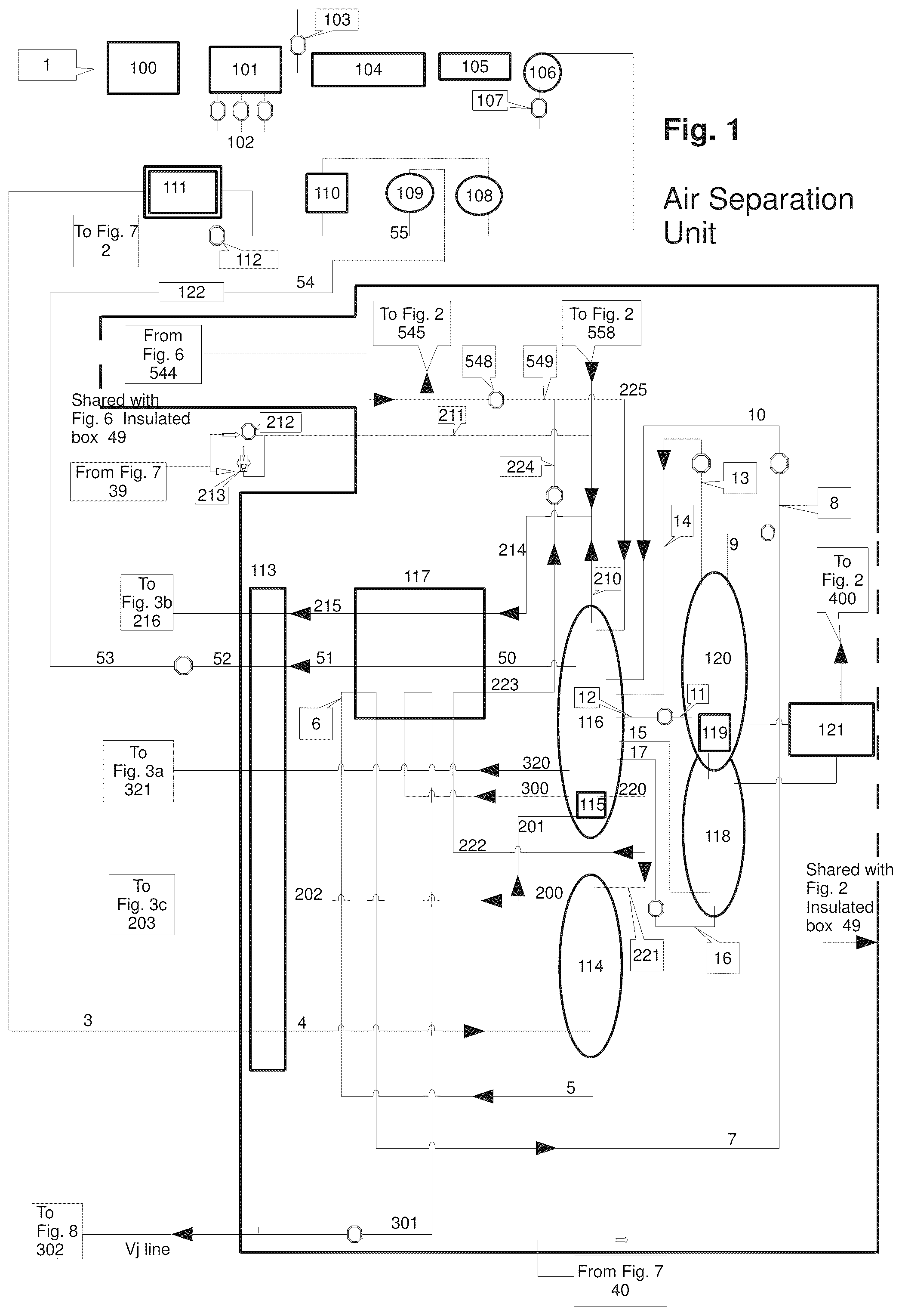
In an embodiment, the liquefier device is one part of an air separation plant, and in another embodiment is a retrofit to an existing plant. The same process can take almost any gas to a liquid. For purposes of illustration, there is shown diagrammatically in an air separation plant having an air flow coming in of 780,000 SCFH at the inlet meter point 111 . The nitrogen, points 203 and 216 in , and oxygen, point 321 in , utilized by the liquefier device of the invention is produced by high pressure column 114 and low pressure column 116 (there are some plants that have three main columns) of the air separation plant. These nitrogen and oxygen flows will exit from a stable running air separation plant's main heat exchanger 113 warm side as pure oxygen gas at 321 , and the two streams of nitrogen gas at 203 and 216 in to be liquefied. In the illustrated embodiment, the liquefier device will be part of a retrofit to an existing air separation plant. All air separation plants can use this liquefier. In , the oxygen at point 321 exits the main heat exchanger 113 warm side with a temperature of 37 degrees Fahrenheit at a pressure of 19.9 PSIA and a flow of 161,521 SCFH. The nitrogen stream exits the main heat exchanger 113 to point 216 at 14.94 PSIA with a flow of 371,185 SCFH holding 37.29 degrees Fahrenheit, and the nitrogen stream exits heat exchanger 113 to point 203 at a pressure of 67 PSIG with a flow of 211,000 SCFH holding 37 degrees Fahrenheit.
The oxygen stream 321 and the nitrogen streams 203 and 216 are fed to the liquefier device, which is an open loop refrigeration unit that takes in the separate streams as a pure gas and which streams will exit the liquefier device as a saleable liquid nitrogen at point 537 (see ) and liquid oxygen at point 381 (see ). The liquefier device of the present invention has significantly reduced power requirements as compared to conventional liquefiers and therefore can produce saleable liquids less expensively.
The present system takes advantage of many properties of liquid nitrogen. One of these properties is that liquid nitrogen is mostly a non-compressible fluid that can be pumped up in pressure which occurs in the liquefier device at point 528 ( ), which will take less force than compressing a compressible gas to achieve runnable pressures. The liquid nitrogen streams can be brought up in pressure by a pump (either liquid nitrogen pump 169 or 170 in ), which pump in the embodiment shown is using less than 100 horsepower. Then, the liquid is brought to a heat exchanger (boiler 145 in ) where the pumped liquid at point 528 in is boiled to a vapor point. The pressure vapor point of the vapor is held back by the four variable guide vanes 154 , 158 , 162 , and 166 in the turbines, all of which are shown in . The vapor produced can then be used to run the four turbine expanders 153 , 157 , 161 , and 165 , also shown . The exit of the turbine expanders at point 450 in yields a lower pressure gas, with a temperature almost at its boiling point, which is directed into a phase separator 151 and then to add refrigeration to the condenser 146 in , which makes more liquid. The turbine expanders' exiting gas will remove the latent heat of vaporization from the higher pressure nitrogen stream at point 500 to the point 149 , and the lower pressure oxygen stream at point 332 to the point 305 all in .
Some conventional air separation plants might have an oxygen and/or nitrogen pipeline which will take the gas described here to another compressor for the pipeline's use. The remaining gas can be used along with any gas the pipeline compressor would vent from time to time. Although not illustrated, it will be understood that these types of changes are able to be performed with a minimum number of modifications or changes to the air separation plant and the liquefier device of the present invention.
In another embodiment of the liquefier device shown in , the overall flow to the turbine boosters is reduced, which in turn will further reduce the cost of running the turbine expanders and boosters. As another benefit, a smaller turbine and booster can be used. A flow of high-pressure column nitrogen gas from the air separation unit is combined with an equal pressure flow exiting the third turbine booster 163 connected in series. The combined flow may be directed through an auto pressure control valve 455 and passed sequentially through the heat exchangers from the warm side. This will cool the combined flow, with a phase change in the condenser 1400 , which flow is directed into the nitrogen production flash pot 148 . The flow will then join a flow in another line coming off the auto control valve 1015 in a single tube bank such that both flows will exit the production flash pot 148 as a subcooled liquid nitrogen. This subcooled liquid nitrogen will then combine with another flow of subcooled liquid nitrogen from a load control nitrogen flash pot 1018 tube side exit, which liquid nitrogen is then directed to a nitrogen low pressure storage tank 171 . In this embodiment, there is no need to boost the pressure of the flow of the high-pressure column nitrogen gas ( c , 239 ) from the air separation unit higher, as it can be liquified at exiting pressures. Also, the exit pressure of the nitrogen gas flow out of the third booster 163 is the same as the high-pressure column nitrogen gas inlet flow from the air separation unit. This is another way to unload the last turbine booster 167 connected in series, which will also unload the turbine expander side. At times, the daily ambient temperature will vary higher and lower, which will lead to loading or unloading the last turbine 167 . The last turbine 167 will be designed to normally run at about 85% full load.
Additional areas of applicability for the present invention will become apparent from the detailed description provide hereinafter. It should be understood that the detailed description and specific examples of this preferred embodiment of the invention are intended for purposes of illustration only, that the temperatures, pressures, and purities shown here are close to actual readings but may not be exact, and are not intended to limit the scope of the invention. Other embodiments could be, for example, for the production of liquefied natural gas.
BRIEF DESCRIPTION OF THE DRAWINGS
The present invention will become more fully understood from the detailed description and the accompanying drawings, wherein:
is a schematic diagram of a main plant air separation unit configured for operation with the liquefier device of the present invention.
is a schematic diagram of the general operation of the argon liquefaction system in accordance with the present invention.
a - 3 c are schematic diagrams of the oxygen and low and high pressure inlet piping for the liquefier device of the present invention.
is a schematic diagram of the heat exchangers of the liquefier device of the present invention.
is a schematic diagram of the turbine and booster system of the liquefier device of the present invention.
is a schematic diagram of the liquid nitrogen pump system of the liquefier device of the present invention.
is a schematic diagram of the backup gas nitrogen system of the liquefier device of the present invention.
is a schematic diagram of the air separation plant liquid oxygen filter house.
is a schematic diagram of the heat exchangers of another embodiment of the liquefier device of the present invention.
is a schematic diagram of the turbine and booster system of the embodiment of the liquefier device shown in .
DETAILED DESCRIPTION OF THE INVENTION
The following detailed description is of the best mode or modes of the invention presently contemplated. Such description is not intended to be understood in a limiting sense, but to be a non-limiting example of the invention presented solely for illustration thereof, and by reference to which in connection with the following description and the accompanying drawings one skilled in the art may be advised of the advantages and construction of the invention. Wherever possible, like numerals will be used throughout the drawings to refer to like and corresponding parts (elements) of the various drawings.
The following detailed description will describe the liquefier device of the present invention with reference to an air separation plant site having an inlet gas air flow of 780,000 standard cubic foot per hour at the inlet meter box, and will make over 650 tons a day of saleable liquids, running with the liquefier device.
THE BASE LINE. The inventor will first explain one way an air separation plant making over 650 ton a day of liquid product could run. The following explanation is based on an oxygen content of 4 ppm and zero argon on all pure nitrogen streams, and on a standard cubic foot of gas at one atmosphere and at 70 degrees Fahrenheit. The plant site location is around sea level, with an 80 degree Fahrenheit dry bulb temperature and a 70 degree Fahrenheit wet bulb temperature. In addition, the Table included herein provides temperature, pressure, and flow readings for each reference numeral point or step within the air separation plant and liquefier device assembly as described herein with reference to through 8 , as well as the Figure location.
THE AIR SEPARATION PROCESS. Referring now in particular to , the air around us is the air 1 used by the air separation plant to make saleable liquids, and initially is to be filtered at filtering system 100 . Normally there is a four-stage compressor 101 used to bring up the air to a runnable pressure, and three intercoolers that will remove condensed water at 102 . After the fourth compression stage there is a possible vent valve 103 which is normally closed. The compressed air is now cooled with a fan cooled aftercooler 104 , then cooled again with refrigeration unit 105 . Water is condensed during compression and is sent to the water separation unit 106 where the water is removed at 107 . The air is still holding a lot of moisture and must be dried down to −110 degrees Fahrenheit due point, which is achieved by a molecular sieve bed 108 . The drying action will break up a small amount of the sieve material into a fine dust that is now removed by the dust filter 110 . The air is now ready to use.
There is a line to the instrument air supply header controlled by an on/off valve 112 normally open to send a supply of filtered air to the backup gas nitrogen system (see ) at point 2 . All the rest of the air is metered at 111 and sent through line 3 entering the insulated cold box 49 to the main heat exchanger 113 . The air exiting the main heat exchanger 113 in line 4 is sent to the third tray of the high pressure column 114 . Condensed liquid will fall to the bottom of the high pressure column 114 and will be removed in line 5 . This liquid at point 6 must be cooled by a subcooler 117 prior to being elevated in line 7 to point ( 8 ) and split into either line 9 to the top of crude argon condenser 120 or into line 10 to the 44th tray of the low pressure column 116 . Referring again to the high pressure column 114 , the rest of the gas that entered into the column 114 moves up the column through 38 trays and is removed at the top of the column 114 in line 200 as pure nitrogen gas. The nitrogen gas in line 200 splits off to line 201 which leads into the tube side of the reboiler 115 inside the low pressure column 116 bottom liquid. The reboiler 115 will condense the gas nitrogen to a liquid nitrogen. This liquid nitrogen flow exiting the reboiler in line 220 will also be split, with most of the liquid nitrogen to be returned to the high pressure column 221 , and the rest will be directed in line 222 to the subcooler 117 .
In addition to splitting off to line 201 , there is a stream of pure nitrogen gas off the high pressure column 114 in line 200 that will be removed in line 202 to the main heat exchanger 113 , where the gas nitrogen stream is warmed and exits the main heat exchanger 113 at point 203 . The gas is then directed to the high pressure nitrogen inlet line to the liquefier, shown in c . Referring again to , most of the liquid nitrogen flow in line 220 exiting the reboiler 115 is directed in line 221 to the high pressure column 114 , but the remainder is directed in line 222 to the subcooler 117 . The subcooler 117 will remove more heat from the liquid flow so that upon exiting the subcooler 117 in line 223 , the flow can be used in the low pressure column 116 without a major flash off. The liquid is elevated to the top of the low pressure column 116 to a control valve in line 224 that will meter and depressurize the flow. The amount of liquid nitrogen needed to make up the heat loss of the main operation is added at point 549 from point 544 ( ), which is the flow from the new liquefier. Prior to reaching point 549 , the flow of liquid nitrogen from point 544 is split, such that one flow is directed to the pure argon system ( point 545 ) and another flow is directed to a control valve 548 that will meter and depressurize the flow at point 549 , which as indicated above is joined by the flow in line 224 resulting in a joined flow in line 225 .
The joined flow 225 will enter the low pressure column 116 at tray 65 . The gas at the top of the low pressure column 116 exiting in line 210 is mostly nitrogen. The liquid nitrogen from the liquefier device in line 544 that is directed to the pure argon system ( , point 545 ) will return as a low pressure nitrogen gas ( point 558 ) and is joined with the low pressure 210 nitrogen gas exiting the low pressure columns 116 in line 210 , and the joined flow in line 214 is directed to the subcooler 117 . The exit of the gas nitrogen from the subcooler 117 in line 215 will now enter the main heat exchanger 113 , and the low pressure nitrogen gas then exits the main heat exchanger 113 to the low pressure nitrogen inlet line to the liquefier device of the present invention, shown at point 216 in b.
Referring again to the low pressure column 116 in , going down the column to tray 55 , this is the point where waste nitrogen and a large amount of carbon monoxide will exit the process. The waste nitrogen stream 50 exits the low pressure column 116 to the subcooler 117 . At the exit of the subcooler ( 117 ) in line 51 the waste nitrogen stream enters the main heat exchanger 113 , and then exits the main heat exchanger 113 in line 52 as a warmed stream to a control valve where the flow is metered. After the control valve the warmed waste nitrogen stream in line 53 is then used to reactivate the molecular sieve bed 109 , which is offline. The waste nitrogen stream 53 is therefore sent to the tube side of a gas fired heater 122 and then will exit in line 54 to the top of the offline molecular sieve bed 109 . The bed is first heated, then cooled by the waste nitrogen, and the gas will exit to atmosphere at line 55 . Referring still again to the low pressure column 116 , going down the column to tray 44 , this is the location where the liquid in line 10 from the bottom of the high pressure column 114 will enter. The liquid in line 9 from the bottom of the high pressure column 114 enters the crude argon condenser 120 , where it is used to condense the crude argon in the tube side of the reboiler 119 . A small amount of the liquid from the bottom of the high pressure column feed in line 9 will be removed in line 11 , where it is metered and then sent in line 12 to the low pressure column 116 tray 42 . The rest of the liquid from line 9 exiting the bottom of the high pressure column 114 is vaporized during the condensing of the crude argon in the reboiler 119 . The gas formed from such vaporization exits the high pressure column 114 in line 13 and is metered by a control valve and afterwards is brought line 14 to the 43rd tray of the low pressure column 116 . Going down the low pressure column 116 to tray 24 , this is the location where the amount of argon gas is the highest in the low pressure column. This gas is fed line 15 to the crude argon column 118 . The liquid at the bottom of the crude argon column 118 exits in line 16 to a metered control valve. After the control valve the liquid in line 17 is sent back to the 24th tray of the low pressure column.
Staying with the crude argon column 118 , the gas in line 15 from the low pressure column 116 enters the crude argon column and rises to the reboiler 119 through 38 trays. The gas will turn into liquid and gas in the reboiler 119 tube side. The liquid and gas will exit to the phase separator 121 , and the gas off of the phase separator 121 is directed to the argon liquefaction system ( , point 400 ). The liquid from the phase separator 121 is directed to the crude argon column 118 , tray 38 . Back to the low pressure column 116 , going down the column to just below the tray number one, the gas found here is called “pure oxygen.” The gas oxygen will be removed from the low pressure column 116 in line 320 to the main heat exchanger 113 where the gas is warmed. After the heat exchanger, the warmed gas is directed to the oxygen inlet line to the liquefier device (see a , point 321 ). Back to the low pressure column 116 , the bottom liquid is “pure liquid oxygen.” The reboiler 115 is changing the liquid oxygen into gaseous oxygen that drives the low pressure column 16 . Most of the gas will go up the column, but the process of removing a large amount of gas oxygen will cause a lower pressure. The lower pressure will mean a lower temperature, which will lower all running pressures all the way back to the main air compressor 101 . The small amount of liquid oxygen will need to be removed in line 300 to flush out the solid contamination. This liquid oxygen will be sent to the subcooler 117 , and after the subcooler 117 the flow in line 301 will be metered but the level control of the reboiler height will be valves 336 , or 343 , or 357 in . The liquid oxygen flow is sent to at point 302 . Also referred to at the bottom of is point 40 from , which is a cold box nitrogen purge used to keep a positive pressure on the insulated cold box 56 to keep out the wet air. Another set of points come around the low pressure column 166 feed 211 to the safety relief valve 213 and burst disk 212 , which set up is cold and needs a warming nitrogen flow which it receives from point 39 to ensure it works when needed.
THE PURE ARGON SUBSYSTEM. Referring now primarily to , there are two major flows shown, one of which is the nitrogen for cooling, and the other is the argon to process. The nitrogen flow comes in from , point 545 as a cool liquid nitrogen that will branch off to two control valves, both of which control valves control the liquid nitrogen baths they are supplying. The flow out of line 546 is to the pure argon recondenser holding tank 126 that will bottom fill the heat exchanger 125 shell side. The liquid nitrogen will be vaporized and exit in line 555 to a pressure control valve and then to line 557 . The second flow from , point 545 , goes to another control valve set to hold a liquid level in line 547 on the shell side of the pure argon column condenser 131 . This liquid nitrogen will be vaporized and exit the condenser 131 in line 556 to a pressure control valve, after which it will join line 557 and head back to the main air separation unit at , point 558 .
The argon to process comes in from , point 400 . This crude argon flow will enter the cold side of argon heat exchanger 133 and exit warm in line 401 heading to a joined flow with line 403 of hydrogen. The joined flow 404 is directed to the argon compressor 134 , which is a two stage compressor with one intercooler. The compressed argon hydrogen flow exiting the argon compressor 134 in line 405 is cooled by an after cooler 135 and exits the aftercooler 135 in line 406 to be joined by a make-up flow of hydrogen. The make-up flow of hydrogen comes from a tube trailer 136 , exits to a small line 407 then is pressure regulated to supply 408 to the compressed argon hydrogen flow 406 to make the combined flow 409 to the argon flash arrester 137 . Upon exiting the flash arrester 137 at line 410 , the flow is directed to a deoxo-catalyst bed 138 where the hydrogen and oxygen in the argon will be combined to make water vapor. The name of the flow at this point changes to combusted argon. The exit of the deoxo-catalyst bed 138 in line 411 is very hot with a lot of humidity. The combusted argon flow is now cooled by an aftercooler 139 , after which the high humidity will now be water in line 412 . Next, the water is removed using a phase separator 140 with a bottom water drain control valve exiting to atmosphere at 432 . The combusted argon is still at 100% relative humidity upon exiting the phase separator 140 in line 413 . The combusted argon must be dried to −110 degrees Fahrenheit dew point, and so the flow is sent to a drier bed 141 . At the exit of the drier bed 141 in line 414 there is some dust with the combusted argon, which is removed by a dust filter 143 . Now the combusted argon in line 402 is dry, dust free and ready to be used, and is directed to an argon heat exchanger 133 .
The combusted argon 402 is warm as it enters the argon heat exchanger 133 . At the cold side of the argon heat exchanger 133 the flow 415 is directed to a hydrogen separator 127 and is almost forming a liquid as it enters the hydrogen separator 127 . The gas in line 416 upon exiting the hydrogen separator 127 will rise to the tube side of the argon reboiler 128 due to the condensing action of the reboiler. The reboiler 128 is not cold enough to liquefy the left over hydrogen from the deoxo-catalyst bed 138 , and therefore will collect at the top of the reboiler tube side and all the argon and nitrogen will liquefy and fall at 417 to the bottom of the hydrogen separator 127 , as there are no trays here. The hydrogen at the top of the reboiler is removed at 419 to a flow control valve and is sent back in line 403 to joined suction flow 404 of the argon compressor.
The liquid at the bottom of the hydrogen separator 127 is removed at 418 to a level control valve that in line 420 feeds the pure argon column 130 . This flow contains argon and nitrogen, with a trace of oxygen and hydrogen. This liquid was not subcooled and will flash after decompression. The liquid and gas mixture will separate, and the gas will rise through distillation trays and the liquid will overflow the tray to the tray below until it collects at the bottom.
The liquid at the bottom of the pure argon column will first collect around the outer shell ring 129 of the reboiler shell side 128 , and after that ring is full, the liquid will fill the bottom of the pure argon column 130 . This liquid is then removed at 425 to a level control valve and is joined at 427 with the recondensed argon in line 431 heading to the pure argon tank 124 . The gas that entered the pure argon column 130 will rise through distillation trays until it is condensed in the tube side of the condenser 131 . The condenser 131 shell side is full of liquid nitrogen, and this makes it cold enough to liquefy in line 421 the nitrogen in the argon but will not liquefy the hydrogen. The liquid and gas bubbles will be removed in line 422 to the phase separator 132 . A small amount of gas is removed to a flow control valve that exits at 423 to atmosphere. This valve is always very cold and needs a warming purge flow, which is received from the backup gas nitrogen system ( , point 37 ). The liquid of the phase separator 132 exits in line 424 back to the pure argon column 130 top tray and acts as a cold cap stopping gas argon from passing.
The argon in the storage tank 124 has a vent line 428 , and the argon transport trailer 123 has a similar vent line 429 both of which will vent excess pressure through a vent auto pressure control valve. The vented gas will share the same line at 430 to the tube side of the argon recondenser 125 where it will be liquefied, and in line 431 the liquid is returned to the joined line 427 to the argon storage tank 124 .
There are two argon dryer beds used in this process, identified in at 141 and 142 . As illustrated in , dryer bed 141 is shown as the dryer being used, and dryer 142 is on reactivation. The reactivation is performed by the nitrogen off of the purge header from , point 36 . The dryer vessels have their own heaters and only need a dry gas nitrogen to move the contamination out to vent at 433 .
THE TAKE OR VENT INLET PIPING TO THE LIQUIFER. As illustrated in a - 3 c , there are three inlet flows to the liquefier, all three of which come from the air separation plant main heat exchanger's warm side ( ). These are the gas oxygen inlet flow, the gas nitrogen inlet flow from the low pressure side of the air separation plant main heat exchanger's warm side, and the gas nitrogen inlet flow from the high pressure column.
Referring now to a , the gas oxygen inlet flow as shown comes from the warm side of the main heat exchanger, , point 321 . This gas oxygen flow is now controlled by a flow meter 325 in order to prevent or stop an over draw of production. The flow is set by the air separation plant, and if the reading of flow meter 331 is not equal to flow meter 325 then any excess flow will be vented. The venting of excess gas oxygen is seen by flow meter 327 , which controls the vent valve 329 . If the pressure is too high the relief valve 328 will open. If the flow meter 327 shows a flow, then there is a problem. Valve 326 is the main flow control. There is a check valve 330 feeding the flow meter 331 . The exit of the inlet process is oxygen gas to the liquefier at , point 332 .
In b , the low-pressure gas nitrogen flow is shown coming from the warm side of the main heat exchanger in , point 216 . This low-pressure nitrogen flow is now controlled by flow meter 250 to stop an over draw of production. The flow is set by the air separation plant, and if flow meter 256 is not equal to flow meter 250 then any excess will be vented. The venting of excess is seen by flow meter 252 which controls the vent valve 254 . If the pressure is too high the relief valve 253 will open. If the flow meter 252 shows a flow, then there is a problem. Valve 251 is the main flow control. There is a check valve 255 feeding the flow meter 256 . The exit of the inlet process is to the liquefier at , point 257 .
In c , the gas nitrogen flow from the high-pressure column comes from the warm side of the main heat exchanger in , point 203 . This high pressure nitrogen flow is now controlled by flow meter 231 to stop an over draw of production. The flow is set by the air separation plant, and if flow meter 237 is not equal to flow meter 231 then any excess will be vented. The venting of excess is seen by flow meter 233 which controls the vent valve 235 . If the pressure is too high, the relief valve 234 will open. If the flow meter 233 shows a flow, then there is a problem. Valve 232 is the main flow control. There is a check valve 236 feeding the flow meter 237 . There is also a two-inch branch line feeding an on or off valve 238 that feeds a purge nitrogen gas supply to , point 33 . The main exit of the inlet process is to the liquefier in , point 239 .
THE LIQUIFIER. Referring now to , the heat exchangers and flash pots for the liquefier device are illustrated diagrammatically. This is located in a well-insulated box 48 with a nitrogen purge coming in from the backup gas nitrogen in , point 41 . The three gas streams described with reference to a - 3 c from the air separation unit will enter the liquefier at different points. The oxygen gas stream comes into the liquefier device cold box from a , point 332 . The oxygen gas stream flow is passed sequentially through three heat exchangers, namely, oxygen cooler 144 , boiler 145 , and condenser 146 , and then enters the tube side of oxygen flash pot 147 . The exit of the flash pot tube side will be a subcooled liquid oxygen, which is directed to the liquid oxygen filter house shown in , point 305 . The draw of oxygen will be the change of state from gas to liquid. There is a change of pressure needed to make the pressure of the liquid oxygen here higher than the low-pressure column's feed. This change in pressure is accomplished by the height of the flash pot 147 . The flash pot 147 should be about fifteen feet higher than the low pressure liquid oxygen line off of the low pressure column heading to the oxygen filter house. This means the gas oxygen stream to the flash pot should not be cold enough to condense prior to the entrance to the flash pot 147 .
The low pressure nitrogen gas stream to the liquefier device comes in from b , point 257 . This low pressure nitrogen stream joins the flow downstream from pressure exit control valve 264 , and the combined flow in line 265 exits to the turbine boosters in , at point 265 .
The high pressure column gas nitrogen stream to the liquefier device comes in from c , point 239 . This stream joins the equal pressure flow downstream from the line exit of control valve 455 , forming the combined flow 462 . This combined nitrogen stream flow 462 will now branch off to two lines containing control valves 456 and 457 . Control valve 456 will add heat to the heat exchanger 152 called the preheater. The exit of the preheater 152 and the exit of the auto control valve 457 will join and exit to turbine package in , at point 458 .
In addition, there is a flow from the turbine package or assembly, , point 273 , to an auto control valve 274 ( ) that will add heat to the preheater 152 and exit back to the turbine at , point 275 . There is also a flow off of the boiler 145 going to the preheater 152 that needs to be warmed prior to being decompressed as shown , point 288 .
The major flow of compressed nitrogen gas from the turbine assembly at , point 500 branches off to three auto control valves 501 , 502 , and 503 . Auto control valve 501 will be set to warm the oxygen cooler 144 . The exit of the flow 501 will join the exit flows of 502 and 503 . The exit of auto control valve 503 will warm the preheater 152 . The auto control valve 502 will bypass the heat exchangers and move a warm gas flow into the boiler 145 . The boiler 145 has a liquid nitrogen bath that must be boiled away. The gas nitrogen from the three auto control valves ( 501 , 502 , and 503 ) will boil the liquid nitrogen in the boiler 145 . The gas from line 500 , will be cooled off but will not condense, but the liquid nitrogen bath in the boiler 145 will turn to gas nitrogen. The cooled-off gas nitrogen from point 500 will go to the next heat exchanger 146 called the condenser, where the gas nitrogen is exchanging its heat with the exhaust of the four turbines, making the gas into a two-phase liquid gas nitrogen stream.
The two-phase stream is sent to the next heat exchanger 150 called the added cooling heat exchanger. Here the two-phase nitrogen stream will be cooled a little more but will still be a two phase stream at the exit. The two-phase stream is then directed into the pump flash pot 149 tube side where the nitrogen stream will be all liquid. The exit temperature at the pump flash pot 149 will be set to hold a boiling point of the boiler 145 after the pump. The liquid nitrogen is cold enough to be used. The liquid nitrogen off of the pump flash pot 149 will branch off to five places, which are to the liquid nitrogen pump ( point 510 ), then to the air separation plant ( point 511 ), then to the auto control valve 512 back feeding the pump flash pot 149 , then to the tube side of the nitrogen production flash pot 148 , and lastly to the auto control valve 513 feeding the shell side of the oxygen production flash pot 147 .
Transition from to . Following the flow of liquid nitrogen off of the pump flash pot 149 to the liquid nitrogen pump ( point 510 ), this liquid nitrogen flow can bypass the pump during start up, through a branch line containing valve 522 . After the pump is running, there is a check valve 523 which will stop a back flow until the valve 522 is closed. A flow from the auto control valve 522 through check valve 523 can supply the boiler through line 528 (to ) and the pump flash pot through line 529 to valve 530 in . [As an operation note, starting a pump sometimes needs priming, and the priming can be done to a low pressure point using the pump flash pot shell side through , point 529 opening valve 530 as valve 522 (in ) is closing.]
Two separate liquid nitrogen pumps 169 and 170 are shown in , which are used for the movement of the liquid nitrogen to the boiler. Two pumps 169 and 170 are provided because the carbon seal on the pumps will wear out, and providing two pumps will allow the operation to stay running as the pumps are switched to replace the carbon seal. Only one pump should be running at a time. In , the inlet valve to the pump 169 is auto valve 520 , and the exit valve is auto valve 524 , which will feed a check valve 526 . The inlet valve to the pump 170 is auto valve 521 , and the exit valve is auto valve 525 , which will feed a check valve 527 . Flow from the pump in use will branch off to the heat exchangers in , point 529 to check valve 530 feeding flash pot 149 , and , point 528 , where it will feed the boiler 145 . The amount of liquid to the boiler 145 will be regulated by the bypass level control valve 523 if the pump is off, or a slowly changing pump speed. The flow from , line 529 to goes to auto control valve 530 . The flow through level control valve 530 is to the shell side liquid level of the pump flash pot 149 and this is normally closed.
The next branch off of the pump flash pot 149 in is to , point 511 . There is a dump to atmosphere branching from line 511 through auto control valve 542 . Line 511 also leads to a normal running open valve 543 this will close check valve 541 and go to line 544 as the liquid back to the air separation plant (see ). If the liquefier is not able to feed the air separation plant, then liquid from the nitrogen storage tank 171 is used. A liquid flow off the nitrogen storage tank 171 is provided by opening valves 539 and 540 . After starting the liquid pump 172 the nitrogen flow will go to check valve 541 , then to a closed auto valve 543 , then to line 544 feeding the air separation plant. At all times, the flow to the air separation plant is controlled by the level controls of the pure argon condenser 131 flow through line 547 , the level controller of pure argon recondenser 126 flow through line 546 , and the metered flow at line 549 to the low pressure column.
The next branch off from the pump flash pot 149 is to the level controller valve 512 ( ) sending liquid back to the shell side of the pump flash pot. This is normally closed. The next branch off from the pump flash pot 149 is to the level controller valve 513 ( ) sending liquid to the shell side of the oxygen production flash pot ( 147 ). This is also normally closed.
The last branch off from the pump flash pot 149 is to the tube side of the nitrogen production flash pot 148 ( ). The liquid nitrogen exiting the flash pot 148 branches to valve and to line 515 (see ). The valve 514 is a liquid level control valve to control the liquid height of the shell side of the nitrogen production flash pot 148 . This is normally closed. The branch off to line 515 is the production liquid nitrogen to the nitrogen storage system. If the production is not good, it will be sent to dump through valve 535 . When the liquid nitrogen is found to be good there is a last purge valve 536 prior to the tank valve which is normally closed. The valve is the production metering valve and is the entry to the nitrogen storage tank 171 . The nitrogen storage tank 171 will be monitored to one PSIG. The tank venting will be through valve 538 to atmosphere. The liquid temperature to control the venting will happen in the production flash pot liquid level and the gas exit pressure 459 (see ).
Referring now to the liquid nitrogen feed to the boiler 145 in from line 528 , , after the liquid nitrogen leaves the pump flash pot 149 , the liquid must be cool enough to stay as single phase liquid thru the pumping stage then up to the boiler, but not be too cool to stop the boiling action when it enters.
Vaporized nitrogen coming out of the boiler 145 is routed to the preheater 152 . The preheater 152 can be warmed by three flows, namely: the booster four aftercooler exit called the major flow controlled by valve 503 , the booster one aftercooler exit controlled by valve 274 , and the high pressure column and turbine exhaust flow controlled by valve 456 . This can be monitored by the auto opening of valve 451 . Valve 451 will drain excess liquid produced by the four turbines that is not used by the three flash pots.
The exit of the vaporized nitrogen flow from the preheater 152 goes to the turbine assembly illustrated in , at point 288 . This nitrogen gas is sent to four flow meters 289 , 290 , 291 , and 292 . Each flow meter is connected to its own turbine expander and sets the variable guide vanes for each turbine expander. Flow meter 289 is the inlet to turbine expander 153 . Flow meter 290 is the inlet to turbine expander 157 . Flow meter 291 is the inlet to turbine expander 161 . Flow meter 292 is the inlet to turbine expander 165 . The guide vanes 154 of turbine expander 153 are set by flow meter 289 , the guide vanes 158 of turbine expander 157 are set by flow meter 290 , the guide vanes 162 of turbine expander 161 are set by flow meter 291 , and the guide vanes 166 of turbine expander 165 are set by flow meter 292 . All four turbine expanders exit to a common header with one exit (to , point 450 ).
Point 450 in is where the exit from the four turbine expanders goes into a phase separator 151 . The phase separator 151 will hold a liquid level controlled by the exit temperature of the turbines and the draining four auto control valves. The temperature of the turbine exit has to do with the pressure of the boiler 145 and the feed temperature from the preheater 152 . The four auto control valves are the over flow valve 451 , the filling of the shell side of the oxygen production flash pot 147 , valve 452 , the filling of the shell side of the nitrogen production flash pot 148 , valve 453 , and the filling of the pump flash pot 149 , valve 454 .
Filling of the oxygen production flash pot 147 shell side by a level control valve 452 , this should be the only filling valve needed for the flash pot 147 . Another valve 513 is provided in case it is needed but is closed on normal operation. The liquid nitrogen being supplied to the flash pot by level control valve 452 is not subcooled and will flash when decompressed. The rest of the liquid will boil away as the tube side liquid oxygen is cooled. The exit oxygen temperature control is from the liquid height of the nitrogen shell side bath, and the pressure held on the exit nitrogen gas in line 461 . The vent valve 382 on the oxygen storage tank 177 (see ) is the only a pressure control valve on the tank, but the valve should not be always open. The opening of the vent valve should be monitored and the temperature of the oxygen production flash pot 147 should be controlled. The oxygen storage tank should never run below 0.5 PSIG or above 1.5 PSIG without an adjustment, and the vent valve 382 will open at one PSIG.
Looking at the nitrogen production flash pot 148 in , auto level control valve 453 is the only valve that should be used to fill the shell side of the nitrogen production flash pot 148 . Valve 514 is also there if needed but is closed during normal operation. This liquid nitrogen passing through control valve 453 will come in without subcooling and will flash when decompressed. The rest of the liquid to the shell side from valve 453 will be boiled off, as the liquid nitrogen on the tube side is cooled. There is a vent valve 538 on the nitrogen storage tank 171 (see ). The exit production liquid nitrogen temperature control is from the liquid height of the nitrogen shell side bath, and the pressure held on the exit nitrogen gas in line 459 . The vent valve on the nitrogen storage tank 171 is the only pressure control valve, but the valve should not always be open. The opening of the vent valve 538 should be monitored and the temperature of the nitrogen production flash pot 148 should be controlled. The nitrogen storage tank 171 should never run below 0.5 PSIG or above 1.5 PSIG without an adjustment, and the vent valve 538 will open at one PSIG.
The pump flash pot 149 has a level control valve 454 which should be the only liquid nitrogen supply to the shell side. Other valves, including valves 530 and 512 , should be closed and are there if needed. The pump flash pot 149 tube side liquid nitrogen must be monitored to control its flash off point. The liquid should be a single phase as it exits the nitrogen pump, but not so cold that it stops the boiler as it enters. The tube side liquid nitrogen therefore has to be monitored, and the shell side liquid nitrogen height and pressure controlled.
After all three flash pots 147 , 148 , and 149 have taken what they need from the three percent of produced liquid off of the turbine exhaust phase separator 151 , there should be a small amount left over. This is passed through a level control valve 451 and liquid that is not subcooled will flash when decompressed. The flashing liquid nitrogen is put into a low pressure line used by the nitrogen production flash pot exhaust gas. As this valve 451 opens and closes it will show how the exit temperature of the four turbines are doing. If the valve 451 closes a little, that shows more liquid is being used by the flash pots, or the preheater is running to warm, or the boiler pressure is changing to a lower pressure.
The three flash pots 147 , 148 , and 149 shell sides will exit gas nitrogen. The oxygen production flash pot 147 will exit the shell side nitrogen gas in line 461 to the condenser 146 . At the exit of the condenser pass there is a branch off to a pressure control valve 260 or a check valve 261 . Check valve 261 will take a small flow during startup to the turbine exhaust header but when the turbine exhaust pressure goes above the flash pot pressure auto pressure control valve 260 will move the gas to a low-pressure line. During normal operation, check valve 261 is closed and pressure control valve 260 is controlling. The nitrogen production flash pot 148 shell side will exit the shell side gas in line 459 to the added cooling heat exchanger 150 , then join with the exhaust from valve 451 , and the joined flow is to the condenser 146 . The flow off of the condenser 146 will pick up the exit of the auto pressure control valves 260 and 262 and then enter the boiler 145 . The gas off of the shell side of the pump flash pot 149 in line 460 will go to the added cooling heat exchanger 150 . The exit off of this pass will go to the condenser 146 and exit to a branch off to a check valve 263 and to an auto pressure control valve 262 . Check valve 263 will take a small flow during startup to the turbine exhaust header but when the turbine exhaust pressure goes above the flash pot pressure, an auto pressure control valve 262 will move the gas to a low pressure line. Normal operation is check valve 263 closed and pressure control valve 262 is controlling. Now the low pressure line off the three flash pots 147 , 148 , and 149 will go to the boiler 145 , then to the oxygen cooler 144 , and then to auto pressure control valve 264 .
The four turbine exhaust flow at point 450 from , discussed in greater detail below, will go thru the turbine exhaust phase separator 151 , and the gas off the top of the separator 151 will go into the condenser 146 , while all of the liquid of the phase separator 151 will go to the three flash pots 147 , 148 , and 149 and the over flow valve 451 . Upon the gas stream off of the turbine exhaust phase separator 151 exiting the condenser 146 , during a startup mode of operation, this gas stream will pick up the exit of the two check valves 261 and 263 , but during normal operation the pressure of the exhaust of the turbines will be much higher and close both check valves 261 and 263 . The flow of gas from the condenser 146 will enter the boiler 145 , and at the exit of the boiler 145 the gas will enter the oxygen cooler 144 . The exit of the oxygen cooler 144 is to a pressure control valve 455 .
The pressure control valve 264 should run wide open if all the flow from the low pressure nitrogen inlet line ( b , line 257 ) can enter the liquefier. The flows from valve 264 and from b , line 257 will join, and go to the turbines ( , point 265 ). This joined gas nitrogen flow will also join the flow from surge control check valve 272 ( ), then pass through the flow meter 270 . The flow meter 270 is needed to predict a surge on the first booster 155 . The booster 155 will draw in the nitrogen gas and compress the gas. The compressed gas will pick up the heat of compression and will exit to the aftercooler 156 , which is a double air cooling fan system. Each fan in an embodiment is a 25-horsepower belt driven fan, one is a fixed pitch fan, and the other is a variable pitch fan. The aftercooler 156 is set to hold a 90 degree temperature on the compressed nitrogen gas exit.
The nitrogen gas exit from the aftercooler 156 will branch off to three places, namely, a flow to the surge control return gas flow through control valve 271 , a flow 273 to warm the preheater 152 ( ), and a flow to the next booster 159 through check valve 276 . The flow through the auto surge control valve 271 will open if the math surge curve is approached. If the surge control system is called into action, then valve 271 will slowly open and the check valve 272 will open, and the flow to the booster 155 will increase. The surge control system is normally not active but is used on startup. The next flow is to the preheater 152 at point 273 ( ). The pass through the preheater 152 is normally a small flow to keep the line active, but if the system is upset due to a failure of a nitrogen pump 169 or 170 , the boiler 145 liquid will flash to gas, and the excess cold gas to the turbines will cause the turbines 153 , 157 , 161 , and 165 to produce liquid across the blades, and the turbines will all fail. The control valve 274 ( ) is a temperature controller set to hold the flow in line 288 ( ) to about −155 degrees. The exit of flow from auto control valve 274 through the preheater 152 to line 275 ( ) is a very small flow now moved to line 275 in .
The last flow from the aftercooler 156 is to the check valve 276 heading to the next booster 159 . The exit of the check valve 276 is joined with a small flow in from line 275 (from ) that is a cold gas. The small flow of cold gas from line 275 will not move the inlet temperature to the booster 159 by even one degree during normal running. The gas of the check valve 276 will also be joined by the flow from surge control check valve 276 if the surge control system is active. All of the joined flows will enter the flow meter 277 . The flow from flow meter 277 enters the booster 159 . The exit of the booster will enter the aftercooler 160 (having the same design and operation as the aftercooler 156 ). Out of the aftercooler 160 the flow will branch to the auto surge control valve 278 and check valve 279 (having the same design and operation as the surge system 271 ), and the line to the flow meter 280 .
The flow from the surge control system 282 check valve and the flow from the aftercooler 160 will enter the flow meter 280 . The gas will be compressed by the next booster 163 and exit to the aftercooler 164 . The exit of the aftercooler 164 will branch off to the surge control valve 281 and to the booster 167 . The surge control system is normally closed, but for startup valve 281 slowly opens to a check valve 282 which will add flow to the booster 163 inlet.
The rest of the exit flow from aftercooler 164 will go to a joined flow of the surge control system exit check valve 285 and from line 458 from . All the flow is metered by flow sensor 283 used to predict the booster 167 surge. The flow is now called the major flow. In the booster 167 the gas will go up in pressure and temperature. The temperature will be controlled by an aftercooler 168 to hold the temperature at about 90 degrees. The exit of the aftercooler 168 flow will split to the surge control system 284 . The surge control system 284 should be closed on normal operation, but on start up the valve 284 is slowly opened and that gas will move through check valve 285 to the booster 167 inlet. The flow that was not used by the surge controller system will exit to line 500 to as the major flow.
THE BACKUP GAS NITROGEN SYSTEM. Referring now to , the backup gas nitrogen system is shown, which includes a liquid nitrogen storage tank 174 having its own venting system 46 . The liquid nitrogen will move from storage tank 174 into the tube side of evaporators 178 where the liquid nitrogen is changed into a gas nitrogen. At the exit of the evaporators 178 there is a pressure regulator 45 . If the purge nitrogen header should fall below its normal running pressure, then the regulator 45 will open, but otherwise the regulator 45 is closed.
There is an air feed 2 coming from the air separation unit in to the backup gas nitrogen system in , which is to the instrument air supply. In , valve 112 is an open and closed valve feeding air to the auto control valves to open and close the valves the computer is controlling. This flow has above 78 PSIG of air pressure. Check valve 19 ( ) is provided on air feed 2 to stop a back flow of air. The exit of the check valve 19 will enter the selector 20 which will allow the air to pass during normal operation to the instrument air system 21 . If the instrument air supply falls to a lower pressure, then the set point, pressure regulator 30 will take over. Back flow is stopped by check valve 31 .
The gas nitrogen supply coming into the back up gas nitrogen system from c , line 33 can supply all the purge and instrument nitrogen for the whole plant. After the gas nitrogen is supplied, there is a check valve 32 ( ) to protect the pure nitrogen. If instrument air supply point 2 is not up to set point pressure, then the check valve 31 will open and the pressure regulator 30 will now supply the instruments needing nitrogen, this will open to point 21 . The main purge header, shown by the line extending vertically in , will wrap around the whole plant site with a two inch line. The purge header has many branch offs which are also illustrated in . The main supply to the purge header is the feed off of line 33 , c , and if this is not up to pressure then regulator 45 off of the backup tank 174 will supply the nitrogen gas to the purge header.
The purpose of each of the branches off of the main purge header will now be explained. As shown in , there is a branch to , point 44 off of the purge header which provides a nitrogen supply to the oxygen filter house. As shown in , the main flow is to the warming nitrogen flow through flow meter 60 , to open or close auto valve 61 , to check valve 62 , to service the filters 175 and 176 as needed. There is also a branch flow from point 44 off to provide a nitrogen purge flow to the oxygen filter box at point 47 .
There are four separate branches 34 , 35 , 42 , and 43 off of the main purge header to the turbine package shown in . The branch off at point 34 is providing a sealing gas supply in line 75 to turbine 153 and in line 76 to turbine 157 . The branch off at point 35 is similarly supplying a sealing gas supply in line 77 to turbine 161 , and in line 78 to turbine 165 . The branch off at point 42 is supplying the turbine case purge, and the branch off at point 43 is supplying the oil accumulator.
Another flow off of the main purge header is to point 41 in , which is to the liquefier cold box purge. The flow off of point 40 to is to the cold box purge. The flow off of point 39 to is to a warming purge flow to the low pressure column relief valve 213 and burst disk 212 . The flow off of point 38 is a purge flow of warm gas to defrost the backup storage tank vent valve ( 46 ) as shown in . Finally, the flow off of points 36 and 37 goes to . The flow off of point 36 is to regenerate the argon drier beds, and as shown in is working on argon drier bed 142 , this flow will go to atmosphere 433 . The flow off of point 37 will warm up the vent valve to atmosphere off of the separator 13 shown as flow 423 in .
THE OXYGEN FILTER HOUSE. Some air separation plant sites have built-in heat pumps and gel trap filters to remove solid concentrations in the liquid oxygen at the reboiler. Some plants have a filter to the transport trailers at the filling station. Some plants have a filter to the storage system. Those plant sites will not necessarily need the liquid oxygen filter house illustrated in , although the present oxygen filter house will reduce the losses and manpower needs of the existing system after the plant switches to the new liquefier of the present invention.
The inventor's new liquefier takes almost all the oxygen production out of the air separation plant as gas. This will leave behind a small amount of liquid oxygen that has some solid contamination which must be removed to hold down the concentration of the contamination. The oxygen filter house system has two gases and one liquid to move around without blending. The gases here are pure nitrogen gas, and atmosphere air, and the liquid is pure liquid oxygen. To do this, each system must be protected. The best known way to protect a purity is to keep the pressure above atmosphere pressure, and then to use a blocking system, or a way to stop one flow from moving into the next one. Since the pressures here are above atmosphere pressure, a double block and bleed system is used. This will stop flow by a valve whose exit is to atmosphere. If a valve that is used to block a flow were to leak, then that flow could leak but only to the atmosphere, and not to the next product. All the double block and bleed nest of valves must have a relief valve.
The liquid oxygen flow from the air separation plant comes in from to the oxygen filter house in as a subcooled liquid, at point 302 . There is a check valve 335 on the entry to the filter house, which is provided to prevent a back flow of liquid oxygen. If the liquid oxygen in line 302 is not pure enough to put to storage, or if both filters have clogged, the liquid oxygen must go somewhere. One place the liquid oxygen with a bad purity should go is to the dump. But, if the filters are being worked on and are not able to be used, then there is a bypass to allow the solids to go to storage during a short time the filters are being worked on.
If the oxygen produced by the air separation plant is to be dumped, the whole system is assumed to be or going bad. Quick action must be taken, and all the valves to be closed at once are 313, 316, 381, 61, 63, 69, 64, 70, 343, 357, 346, 360, 377, 378, 339, 372, 351, 365, 352, 366, 342, 355, and 369. In addition, all the valves to open at the same time are 68, 338, 345, 376, 359, 315, 66, 72, 341, 350, 364, 354, 368, 371, and 380. The valves to control the flows are valves 312 , 68 , 336 , and 177 . Valve 312 controls the height of the tube side of the oxygen production flash pot vessel 147 ( ). Valve 68 controls the warm nitrogen flow seen at flow meter 60 to a flow of 100 SCFH but will see zero flow signal making the valve 68 to auto flow control to a wide open. Valve 336 controls the liquid height of the reboiler bath vessel 116 ( ). Then the vent pressure control valve 382 on the storage tank, which will hold a one PSIG on the storage tank. This will vent all trapped gas and liquids to a total dump to protect the storage tank from contamination.
When the purity is established, the system of opening the different subsystems starts. The largest flow will be the liquefier oxygen (from , point 305 ) to storage. On production dump the flow from the liquefier past check valve 310 to dump is controlled by valve 312 . When the purity is good from the liquefier, valve 312 continues to dump while auto level control valve 313 is opened in manual mode. The flow to valve 313 just opened will vent out of the bleed valve 315 . Once the liquid oxygen is at a steady flow out of bleed valve 315 , valve 316 is slowly opened, while valve 315 is closed. The flow will then go out the bleed valve 380 . Once the liquid flow is steady from bleed valve 380 and the purity is still good, then valve 381 to storage is opened. The amount of liquid now moving to storage and to dump will cause the auto level control valve 312 to see a lower level than the set point and begin to close. When valve 312 is about 5 percent auto open, valve 313 is put into auto level control auto mode. Auto level control valve 312 is to be set to a higher liquid level control point than valve 313 and is to be kept in auto control mode in case the flow out of the vessel 147 starts to back up so the liquid oxygen will have a place to go. The system as just described has now put liquid oxygen to storage from the liquefier.
When the purity of the air separation plant's liquid oxygen is good, then for a short time the oxygen with all the solids will go to storage during the time the filters are being worked on. The filters must be opened slowly, and dumping or bypass liquid to storage can continue. In the embodiment shown in , filter 175 will be set up to filter, and filter 176 will be put on reactivation. All of the valves in the filter system will be positioned as if you are going to dump with the air separation plant liquid oxygen, and going to storage with the liquefier liquid oxygen, to here. Liquid oxygen from the production plant comes in from , point 302 to a check valve 335 leading to a shell side reboiler level control valve 336 connected to a dump valve 338 . Opening valve 342 will cause a backward flow of liquid oxygen out bleed valve 341 . Once a steady flow of liquid oxygen is seen exiting bleed valve 341 , then valve 339 is opened and valves 341 and 338 are closed. The system is now set up so that the production plant liquid oxygen is bypassing the filters and going to storage. Flow control is still provided from liquid level control valve 336 .
Setting up filter 175 for service. The liquid oxygen is at a good purity and first open reboiler auto level controller valve 343 in manual mode is opened about 25%. This will vent liquid oxygen out bleed valve 345 . When a steady stream of liquid oxygen is detected, then valve 346 is opened, and bleed valve 345 is closed. This will vent liquid oxygen out bleed valve 350 . The line supplying bleed valve 350 is small and it should take a few minutes to cool down enough to allow a steady flow of liquid oxygen to exit. A close eye must be kept on the active liquid controller, as it is very possible to over draw the liquid from the reboiler, and if this is starting to happen the auto controller valve 336 will close. If the liquid from the reboiler is being overdrawn, then for a short time valve 350 should be closed until the reboiler height is reestablished and the auto controller valve 336 reopens. Then, valve 350 is reopened. By monitoring the temperature sensor 348 , the cooling process can be tracked. After the liquid oxygen is flowing at a steady stream out valve 350 and the purity is still satisfactory, then valve 352 is opened to vent out bleed valve 354 and valve 350 is closed. After a steady stream of liquid oxygen is seen exiting valve 354 then open valve 355 and close valve 354 . The reboiler auto controller valve 336 is also then set to a higher level and reboiler auto level controller 343 is set to auto mode with a set point at normal reboiler height. The bypass line is then closed by closing valves 342 and 339 and then opening valves 338 and 341 . The system is now filtering the solids out of the liquid oxygen from the air separation plant, and the liquefier liquid oxygen is joined to storage.
Next, filter 176 is reactivated, going from the same sequence as above. Recap closed valves are 61, 63, 64, 69, 70, 345, 357, 360, 377, 378, 339, 350, 351, 372, 365, 354, 366, 342, 369, 380, and 315. The valves open at this time are 338, 341, 346, 352, 355, 376, 371, 359, 364, 368, 316 and 381. The valves in auto control are 68, 313, 312, 343, 336, and 382.
Bleed valve 364 is open so any liquid could vent, but to make sure valve 61 is opened so that a flow will be started and seen by flow monitor 60 . Flow monitor 60 will be set to 100 SCFH and for now valve 68 will control the flow. Then flow controller valve 69 is opened in manual mode to 25% open, and the gas nitrogen will vent out of valve 72 . Auto flow controller valve 68 will then start to close, because valve 69 is taking some of the flow. Then, valve 70 is opened, and valve 72 is closed. Auto control valve 68 is set to 90 SCFH and auto flow controller valve 69 is adjusted to a set point of 100. If the flow falls below 90 SCFH then valve 68 will be called to open. If valve 68 is called to open, then the operator will be notified. The solid contamination the filter removes will turn to gas before the filter temperature 362 hits-90 degrees Fahrenheit. When the temperature hits-80 degrees Fahrenheit the reactivation is finished. Now, valves 69 , 70 , and 364 are closed, and valve 72 is opened. Valve 68 is in control and set to open if the flow goes below 90 SCFH as seen by flow monitor 60 . Closing valve 61 therefore will stop the entry of nitrogen gas and by default valve 68 will auto open.
Moving to the cool down of filter 176 , the cleaned exit flow of filter 175 is used to cool down filter 176 . Opening valve 351 will vent liquid oxygen out bleed valve 371 . Once a steady stream of liquid oxygen is seen exiting valve 371 , valve 371 is closed, and auto flow control valve 372 is opened, and will be open 25% in manual mode. This will pass a liquid oxygen flow through a check valve ( 373 ), to a flow monitor ( 375 ), and exit valve 376 . Once a steady flow of liquid oxygen is seen exiting valve 376 , then valves 378 and 364 are opened. The cool down flow will be seen on flow meter 375 .
Auto flow controller valve 372 will be put into auto control mode and be set to 100 SCFH controlling the flow seen at flow meter 375 . The cooling process will be seen on temperature monitor 362 . This process of cooling the filter will take hours due to the small flow. Once the temperature monitor 362 reaches a- 250 then the cool down mode is complete, and the filter 176 will be put on standby mode.
To set up a standby mode for filter 176 , the flowing valves must be closed; 351 , 372 , 378 , 364 , and the valves to be open are 371 and 376. The process of standby is to let a cooled filter 176 sit with valves closed. If there is any gas expansion, the vessel is protected by relief valve 363 . In addition, there will be a cycling of opening and closing valve 364 once every ten minutes, since protecting a vessel with only a relief valve may be insufficient in reducing the expansion of gas trapped.
The next mode of operation of the liquid oxygen filters is dull filter running, which is how to move the filtration from one filter to the next. The standby mode is stopped. The only valve in operation on filter 176 is valve 364 , which will open and close on a timer once every 10 minutes for one tenth of a second. This will stop on an open sequence, and valve 357 will open in manual control to 25% open. A flow of oxygen liquid will be seen coming out of bleed valve 359 . Then valve 360 is opened and valve 359 is closed. Liquid oxygen will go out through valve 364 . During the startup of filter 176 the amount of liquid oxygen to be used will cause auto level control valve 343 to start closing. If valve 343 were to close, then the valve opening on auto level control valve 357 which is in manual mode is reduced to 10%. After liquid oxygen is exiting valve 364 then valve 366 is opened, and bleed valve 364 is closed. Liquid oxygen will flow out of bleed valve 368 . After that valve 369 is opened. Now both filters 175 and 176 are filtering.
The next step is to stop filter 175 . Level controller valve 343 in manual is set at 5% open, and level controller valve 357 is put into auto mode with a set point of the reboiler height. This will take about 3 to 5 minutes to settle out, and then valves 343 , 346 , 351 , 352 , and 355 are closed, and valves 354 , 350 , and 354 are opened.
Filter 175 is drained, with any liquid oxygen in filter 175 will drain out of valve 350 as the liquid turns to gas. In addition, valve 61 is opened and auto control valve 63 is set to 100 SCFH. This will vent nitrogen gas out of valve 66 . Then valve 64 is opened and valve 66 is closed. Auto flow control valve 68 is set to open below 90 SCFH, and auto control valve 63 is set to open below 100 SCFH. This should cause valve 68 to close because the flow will be above the set point. The liquid in filter 175 will be draining out of valve 350 .
Filter 175 is put in to heat up, after the liquid is drained out of valve 350 . Then the flow will stay the same. The point to monitor is the filter temperature sensor 348 . When the filter temperature hits-80 degrees Fahrenheit, the heat up is done._To put filter 175 into cool down, the heat up is stopped by closing valves 61 and 63 . This will cause auto flow control valve 68 to open due to a loss of flow. The set point for valve 68 is open below 90 SCFH. Valve 64 is then closed, and bleed valve 66 is opened. Using the clean liquid oxygen out of filter 176 , valve 365 is opened to bleed valve 371 is closed. After valve 371 has a steady flow of liquid oxygen exiting it, then valve 372 is opened and valve 371 is closed. Valve 372 is put in manual mode and open 10%, and once liquid oxygen comes out of valve 376 , open valve 377 and close valve 376 . Flow meter 375 will show a flow and should be set to a flow rate of 100 SCFH and auto flow control valve 372 will be used to control the flow. The flow will exit valve 350 . Once the flow cools down the filter to −250° F. as seen on temperature sensor 348 then the cool down is done.
Put filter 175 to standby mode. Stop cool down and close valves 365 , 372 , 377 , and 350 . Open bleed valves 371 , and 376 . Now cycle valve 350 open and closed once every ten minutes to stop an over pressure.
Put filter 175 into dull operation mode. When needed filter 175 will be put into dull operation with filter 176 . First open auto level control valve 343 in manual mode at ten percent open. This will vent liquid oxygen out of bleed valve 345 . When a steady flow of liquid oxygen exits bleed valve 345 , then open valve 346 , and close bleed valve 345 . The flow will exit valve open valve 350 . The temperature monitor 348 will show the progression of cool down to operation. Once the flow out of valve 350 shows a steady stream of liquid oxygen then open valve 352 and close valve 350 . The flow will now exit bleed valve 354 . Once bleed valve 354 shows a steady flow of liquid oxygen then open valve 355 , and close valve 354 . Now put auto level controller valve 343 into auto mode and set auto level controller valve 357 into manual mode at five percent open. Once the system is working for a few minutes and is stable, then put the filter 176 into stop mode. Put valve 357 into auto level control.
Put filter 176 into a stop mode. The system just switched over from filter 176 on line to filter 175 on line. Now stop filter 176 and close all valves 357 , 360 , 366 , and 369 . Now open 368 , 364 , and 359 . Any liquid in filter 176 will be able to drain out of valve 364 . Then again go through the warmup steps above.
During the operation of the filters there is a differential pressure gauge to show filter clogging. This should be monitored and logged to find out how long the filter can be in operation. The differential pressure gauge for filter 175 is 347, and the filter 176 has differential pressure gauge 361 . This is a list of relief valves found on . On the liquid oxygen from the liquefier to the filter house is relief valve 311 to protect the line if valves 312 , 313 , and check valve 310 closed with liquid oxygen trapped and changing state to a gas. Relief valve 314 is there to protect the line if valves 313 , 315 , and 316 closed with liquid oxygen trapped and changing state to a gas. Relief valve 340 is there to protect the line if valves 339 , 342 , and 341 closed with liquid oxygen trapped and changing state to a gas. Relief valve 349 is there to protect the line and filter 175 if valves 352 , 351 , 350 , 64 , 346 , and 377 closed with liquid oxygen trapped and changing state to a gas. Relief valve 370 is there to protect the line if valves 371 , 351 , 365 , and 372 closed with liquid oxygen trapped and changing state to a gas. Relief valve 374 is there to protect the line if valves 372 , check valve 373 , 378 , 376 , and 377 closed with liquid oxygen trapped and changing state to a gas. Relief valve 344 is there to protect the line if valves 343 , 354 , and 346 closed with liquid oxygen trapped and changing state to a gas. Relief valve 358 is there to protect the line if valves 360 , 357 and 359 closed with liquid oxygen trapped and changing state to a gas. Relief valve 356 is there to protect the line if valves 357 , 343 , 336 , and check valve 335 closed with liquid oxygen trapped and changing state to a gas. Relief valve 67 is there to protect the line if valves 69 , 68 , check valve 62 , and 63 closed with liquid oxygen trapped and changing state to a gas. Relief valve 71 is there to protect the line if valves 72 , 70 , and 69 closed with liquid oxygen trapped and changing state to a gas. Relief valve 363 is there to protect the filter 176 and the lines if valves 366 , 365 , 364 , 70 , 360 , and 378 closed with liquid oxygen trapped and changing state to a gas. Relief valve 367 is there to protect the line if valves 366 , 368 , and 369 closed with liquid oxygen trapped and changing state to a gas. Relief valve 379 is there to protect the line if valves 381 , 380 , 342 , 355 , 369 , and 316 closed with liquid oxygen trapped and changing state to a gas. Relief valve 353 is there to protect the line if valves 352 , 354 , and 355 close with liquid oxygen trapped and changing state to a gas. Relief valve 65 is there to protect the line if valves 63 , 64 , and 66 closed with liquid oxygen trapped and changing state to a gas. Relief valve 337 is there to protect the line if valves 336 , 338 , and 339 closed with liquid oxygen trapped and changing state to a gas.
illustrate another embodiment of the liquefier device heat exchangers and turbine package of the present invention. In this embodiment, there is a reduction in the turbine booster overall flows, which will further reduce the cost of running the turbine expanders and boosters. In addition, a smaller turbine and booster can be used. By taking the flow of high-pressure column nitrogen gas from the air separation unit via inlet piping system point 239 , c and combining this flow with a flow exiting the third turbine booster connected in series, and then directing the combined flow through an auto pressure control valve 455 and a pass through the heat exchangers 1100 , 1200 , 1300 , 1400 , 1500 from the warm side, with a change of phase in the condenser 1400 , into the nitrogen production flash pot 148 , and then joining another line coming off of the auto control valve 1015 in a single tube bank such that both flows will exit flash pot 148 as a subcooled liquid nitrogen which passes through control valve 1016 and across temperature sensor where the temperature is logged. This subcooled liquid nitrogen will combine with another flow of subcooled liquid nitrogen from a load control nitrogen flash pot tube side exit 1018 through a valve pressure reduction 1017 and across temperature sensor 1046 where the temperature is logged, then the combined flow goes to the nitrogen low pressure storage tank, point 515 . In this embodiment, there is no need to boost the pressure of the flow of the high-pressure column nitrogen gas from the air separation unit from point 239 , c any higher, as it can be liquified at the exiting pressure. Also, the exit pressure of the flow out of the third booster is the same as the high-pressure column nitrogen gas inlet flow from the air separation unit. This is another way to unload the last turbine booster connected in series, which will also unload the turbine expander side. At times, the daily ambient temperature will vary higher and lower, which will lead to loading or unloading the last turbine. The last turbine will be designed to normally run at about 85% full load.
In , a low-pressure gas nitrogen stream from the warm side of the main heat exchanger of the air separation unit comes into the liquefier device in an inlet line at point 257 , b . The inlet line containing the low-pressure gas nitrogen stream from point 257 , b joins another line containing a low-pressure gas nitrogen flow coming off of the warm side of counter current flow heat exchanger or warmer 1100 , after passing through an auto pressure control valve 264 . The combined or joined flow of low-pressure nitrogen gas then connects in a line to an inlet to the first turbine booster 155 arranged in series, , point 265 . An oxygen gas stream from the air separation unit comes into the liquefier device in an inlet line from point 332 , a . The inlet line containing the oxygen gas stream enters the liquefier box directly into the warm side of warmer 1100 and exits the cold side. A high-pressure gas nitrogen stream from the air separation unit comes into the liquefier device in an inlet line from point 239 , c . This inlet line containing a high-pressure gas nitrogen stream will join a line containing a high-pressure gas nitrogen flow coming to and from point 458 , and connecting to an exit line containing a nitrogen gas flow from turbine booster aftercooler 164 after passing through turbine booster 163 . This combined high-pressure gas nitrogen flow is connected to pass in a line containing auto pressure control valve 455 into the warm side of the warmer 1100 .
In the exemplary embodiment, starting with the oxygen flash pot 147 , the oxygen gas coming from the air separation unit (ASU) is running about 37° F. with about 5.2 PSIG. This oxygen gas will enter the warmer 1100 warm end and exit the cold end at −184° F. Then, the oxygen gas flow will enter the preheater 1200 warm side at −184° F., and exit this heat exchanger at −240° F. The flow of oxygen gas will enter a tube bank of the boiler 1300 at −240° F. and exit at −250° F. The oxygen gas flow will then enter the warm side of the condenser 1400 at −250° F. and exit the cold side at −285° F. The flow of oxygen gas will then enter the oxygen production flash pot 147 at −285° F., where it will condense to a liquid, and then be subcooled to about −300° F. The oxygen production flash pot 147 will have to be about 15 feet higher than the liquid oxygen line coming from the ASU to the storage line to give it a hydraulic boost to join the line after the oxygen filter that exits to the oxygen storage tank. The condensing action will come from the liquid nitrogen bath in the oxygen production flash pot 147 . This liquid nitrogen bath is supplied in the line containing valve 513 connecting from the liquid exit of the nitrogen pump flash pot 149 exit, and will enter the oxygen production flash pot at −310° F. This liquid nitrogen will form a bath and the level will be monitored by level controller 1043 , and the liquid nitrogen will vaporize as the liquid oxygen is being condensed. The vaporized nitrogen gas will exit to an auto pressure controlling valve 452 . The exiting vaporized nitrogen gas will exit the oxygen production flash pot at −310° F. The exit of the pressure control valve 452 will enter a joined low pressure gas nitrogen line coming from the other flash pots 148 , 149 , and 1018 after passing through nitrogen pressure control valves 453 , 1019 , and 1021 , respectively.
The vaporized joined nitrogen gas from flash pots 147 , 148 , 149 , and 1018 will pass through exit pressure control valves 452 , 453 , 1919 , and 1021 and then enter the added cooler cold side at about −310° F., then will exit to the condenser 1400 cold side at about −285° F. At the warm side exit of the condenser 1400 this low-pressure nitrogen gas flow will be at −250° F. The low pressure gas nitrogen will then enter a tube bank in the boiler 1300 . At the exit of the boiler, the low pressure gas nitrogen should be −250° F. showing no temperature change. The low pressure nitrogen stream then enters the cold side of the preheater 1200 , and exits at about −186° F. The low pressure nitrogen gas stream then enters the cold side of warmer 1100 at about − 186 OF, then exits to auto pressure control valve 264 at a temperature close to the temperature of the flow at point 500 from to the warm side entry to warmer 1100 . This temperature is close to 90° F. The low pressure gas nitrogen that is pressure regulated by valve 264 will blend with a low pressure gas nitrogen coming from b , point 257 , and the combined flow will go to , point 265 .
The next flow is the high pressure column gas nitrogen coming in at point 239 , c . At a location close to the insulated box 48 , the flow is joined with a flow in a line at point 458 , from , from the exit of booster aftercooler 164 . This joined flow from point 458 can go either into the warm side of the warmer 1100 or to the turbine boosters and is a balance point depending on the heat of the day. Higher heat will affect the pressure at the turbine booster inlets, and in response the computer control system will open auto pressure controller valve 455 further. On normal running the flow will come from both points 239 and 458 , although the flow from point 239 will be the larger amount of the flow. The combined flow will enter auto pressure control valve 455 at about 60° F., which flow then enters the warm side of warmer 1100 , and exits the cold side at about −184° F.
The combined high pressure flow then enters the warm side of the preheater 1200 at about −184° F. and exits the cold side at about −240° F. The combined high pressure flow then enters a tube bank inside of the boiler 1300 , and at the exit of the tube bank the temperature should be −250° F. The combined high pressure flow then enters the warm side of the condenser 1400 , and at the exit the
•
• The combined high pressure flow then enters the warm side of the pre heater 1200 at about ˜ 184° F. and exits the cold side at about −240° F. The combined high pressure flow then enters a tube bank inside of the boiler 1300 , and at the exit of the tube bank the temperature should be −250° F. The combined high pressure flow then enters the warm side of the condenser 1400 , and at the exit the temperature should be −280° F. and now a two phase liquid and gas stream. The combined high pressure flow then enters the warm side of the added cooler 1500 at a temperature of close to −280° F. and exits at about −300° F. as a single phase liquid, still needing sub cooling. The combined high pressure flow then enters the tube side of the nitrogen production flash pot 148 , which flash pot has a nitrogen bath at low pressure. The single phase liquid nitrogen flow enters at about −300° F. and exits at about −315° F. holding about 60 PSIG. This is cold enough to put into a one PSIG nitrogen storage tank without a lot of gas off.
In a flow at point 1001 from the turbine phase separator 151 feeds a branch line at point 1002 that goes to the condenser 1400 on the cold side, which flow will exit the warm side. The flow then enters one of five tube banks inside the boiler 1300 . At the exit of this flow's boiler tube bank, it then connects to enter the cold side of the preheater 1200 and then exits the warm side which feeds to the cold side of the warmer 1100 . The flow then exits the warm side of warmer 1100 and is sent to the point 1000 , . Also in , from point 500 , , there is a pressurized nitrogen gas flow to the warmer heat exchanger 1100 warm side. This flow exits the cold side of heat exchanger 1100 at point 1025 to a branch line. One side of the branch line is to an auto temperature controller bypass valve 1005 , while the other branch line enters the warm side of preheater 1200 . Bypass valve 1005 will add more heat to the boiler 1300 if needed.
Referring still to , a line containing a flow of gas coming from , point 450 connects from an exit of the turbine expanders to an inlet into turbine exhaust phase separator 151 . A line containing a flow of exhaust nitrogen gas at point 1001 connects from an exit of turbine exhaust phase separator 151 to a branch line, with one branch side connecting into the cold side of condenser at point 1002 , and the other branch side connecting to a flow exiting from auto level controller valve 451 , which joined flows are directed into the warm side of added cooling heat exchanger 1500 , or added cooler. This combined flow to the added cooler 1500 is a cold nitrogen gas and will change to a two-phase flow inside the added cooler 1500 . The two-phase flow will exit the added cooler 1500 on the cold side and then enter a tube bank of load control flash pot 1018 to produce liquid nitrogen. The load control flash pot 1018 will be oversized and will be set up to condense 40% of the total gas flow coming off the turbine exhaust phase separator 151 from point 1001 . At the exit of the tube bank of load control flash pot 1018 , the liquid nitrogen is subcooled enough to be depressurized down to a pressure of one PSIG with very low flash loss. The tube side will exit to control valve 1017 where there will be a pressure loss, then the temperature will be logged by 1046 , now joining the exit of valve 1016 with temperature logged by 1047 going to the nitrogen storage tank, line 515 , .
A flow of nitrogen gas at point 1002 in the other branch side is directed into condenser 1400 on the cold side and exits on the warm side. The branch then is connected to pass the flow of nitrogen gas from point 1002 into one of five tube banks inside boiler 1300 . At the exit of this boiler tube bank, the line then connects into the cold side of preheater 1200 , and then at the exit of preheater 1200 on the warm side to the cold side of warmer 1100 . The flow exits the warm side of warmer 1100 in a line at point 1000 which connects to an inlet line to the last turbine booster 167 connected in series, shown in . Also in , a pressurized nitrogen flow in a line exiting aftercooler 168 after passing through the last turbine booster 167 , reference to , point connects to the warm side of warmer 1100 . This line exits the cold side of warmer 1100 at point and then as indicated above branches to a line into the warm side of preheater 1200 , and another line including a bypass auto temperature controller valve 1005 which connects back to the other branch line upon exiting the cold side of preheater 1200 .
Warmer 1100 in the exemplary embodiment is a multi-pass counter current flow heat exchanger comprising five passes. One pass is the flow of low-pressure gas oxygen in the inlet line from a , point 332 , that enters on the warm side and exits on the cold side. Another pass is the flow of low-pressure gas nitrogen in the line that enters on the cold side and exits on the warm side and connects to the inlet line of low pressure gas nitrogen from b , point 257 after passing through valve 264 on the warm side. Another pass is the combined flow of high-pressure gas nitrogen in a line connecting from high-pressure gas nitrogen inlet line, c , point 239 and from the turbine booster 163 and aftercooler 164 , point 458 , that enters on the warm side after passing through valve 455 and exits on the cold side. Another pass is the gas nitrogen flow from the branch at point 1002 that as described above enters the cold side of condenser 1400 to the warm side, then enters one of the five tube banks in the boiler 1300 and exits to the warm side, and then enters to the cold side of pre heater 1200 and exits the warm side, then enters to the cold side of the warmer 1100 and exits to the warm side in a line at point 1000 to the inlet line to turbine booster 167 . Another pass is the pressurized nitrogen from , point 500 to the warm side of the warmer 1000 that exits to the cold side shown at point 1025 . The main purpose of warmer 1100 is to process flows having multi-inlet temperatures close to ambient and multi-pressures on the warm side so that the flows exit the cold side at about −180° F., and so that on the cold side nitrogen gas enters at about −185° F. and exits on the warm side at Ambient temperatures.
Preheater 1200 in the exemplary embodiment is a multi-pass counter current flow heat exchanger with six passes. Three passes enter preheater 1200 on the warm side at a temperature of about −180° F. and exit on the cold side at about −245° F., and three passes enter pre heater 1200 on the cold side at about −250° F. and exit the warm side at about −185° F. As discussed above, there is also a bypass line around preheater 1200 from point 1025 containing bypass auto temperature controller valve 1005 . The purpose of the bypass line is to enable the liquefier device control system to monitor and control the temperature of cold nitrogen gas exiting the preheater warm side in a line connecting to the turbine expanders, point 1024 , . Bypass auto temperature control valve 1005 controls the bypass line and is set to hold the temperature of this cold nitrogen gas at around −184° F. ±2° F. The valve 1005 will be controlled by the average temperature of the mass flow sensors 289 , 290 , 291 , and 292 in inlet lines to the turbine expanders 153 , 157 , 161 , and 165 , in . The action of the bypass valve 1005 is to open if the flow warms and to close if the flow is too cold, wherein the amount of movement will ordinarily be small to open or close, with no major moves.
Boiler 1300 in the exemplary embodiment is a shell and five-tube bank heat exchanger, wherein as illustrated diagrammatically in the shell side holds a liquid nitrogen bath with a level controller 1031 , a temperature sensor 1032 , and a pressure sensor 1030 . Liquid nitrogen is supplied by the nitrogen pump system described above with reference to , in a line containing inlet temperature monitor 1049 connecting from point 528 , to the boiler 1300 , . There are five tube banks inside the exemplary boiler 1300 , which will be set to either condense a little gas or boil a lot of liquid. Oxygen gas moving through one of the tube banks is from the oxygen gas stream in the inlet line from point 332 , a after passing through warmer 1100 and preheater 1200 from the warm side to the cold side. This oxygen gas pass is a heat pass to the boiler 1300 and the tube bank will be located in the bottom of the boiler 1300 covered by liquid nitrogen. Another pass is the combined flow of high-pressure gas nitrogen from the inlet line from point 239 , c and from point 458 , after passing through warmer 1100 and pre heater 1200 from the warm side to the cold side, which has a tube bank that is a heat flow to the boiler 1300 and will also be located on the bottom of the boiler 1300 covered by liquid nitrogen. Another tube bank receives the pressurized gas nitrogen flow from the point 1025 , after passing through warmer 1100 and preheater 1200 from the warm side to the cold side, which comprises the largest heat flow to the boiler 1300 and will also be covered by the boiler's bath. There are two tube banks which will not be covered by the bath of liquid nitrogen. One contains the low-pressure gas nitrogen from flash pots 147 , 148 , 149 , and 1018 which is in its own tube bank which is not covered by the liquid nitrogen bath due to its cold gas which will now condense the just boiled gas. The other tube bank not covered by the liquid nitrogen bath is the flow from point 1002 which contains exhaust gas from the turbine exhaust phase separator 151 to point 1001 then to point passing through the condenser 1400 from the cold side. This tube bank will be on the top of the boiler 1300 and will condense a small amount of gas back to liquid. Not all of the tube banks will cause the boiler to boil, but the presently described arrangement will allow larger flow upsets without massive over shooting of the pressure or temperature.
Condenser 1400 in the exemplary embodiment is also a multi-pass counter current flow heat exchanger, wherein the temperature of the warm side will be set to run at about −250° F., and the temperature of the cold side will be set to run at about −287±5° F. Condenser 1400 comprises five passes, three of which provide heat to the exchanger, and two of which are cooling passes. The major cooling flow to the condenser 1400 comes from the turbine phase separator 151 in the line from point 1002 . Another pass is the gas oxygen from point 332 , a after passing through the warmer 1100 , preheater 1200 , and boiler 1300 from the warm side to the cold side. This oxygen gas pass through the condenser 1400 from the warm side has to be sloped higher on its exit than its entry in order to stop a possible flooding of liquid oxygen, as the exit pipe to the flash pot 149 will be elevated about 15 feet. The condenser 1400 has to be placed at a higher elevation than the flash pots 148 , 1018 , and 149 with the passes sloped to the added cooler 1500 to prevent flooding.
•
• Another pass contains the low-pressure gas nitrogen from valves 452 , 453 , 1019 , and 1021 of the flash pots 147 , 148 , 149 , and 1018 after passing through the added cooler 1500 from the cold side to the warm side. Another pass is the combined flow of high-pressure gas nitrogen from the inlet line from point 239 , c and from point 458 , after passing through warmer 1100 , preheater 1200 , and boiler 1300 from the warm side to the cold side. Another pass is from , point 500 to the warm side of the condenser 1400 after passing through warmer 1100 , preheater 1200 with a bypass valve 1005 , and boiler 1300 from the warm side to the cold side as shown.
As indicated, the turbine phase separator 151 receives a very cool nitrogen gas flow in a line from point 450 , exiting the turbine expanders. This flow is near its vapor pressure point at the exit of the turbines. Due to piping turbulence and a minor drop of pressure in this line, the cool nitrogen gas flow will develop droplets that can be removed from the flow, sometimes in quantities of more than 200 gallons per hour. The turbine phase separator 151 has a liquid level sensor 1041 that will control two valves. One is valve 1022 in a line exiting the turbine phase separator 151 , that has a shared signal with level sensor 1042 in nitrogen pump flash pot 149 . A full level signal from level sensor 1042 will cause the control system for the liquefier device to close valve 1022 , and a low level at liquid level sensor 1041 will also signal valve 1022 to close. The second valve is valve 451 , which is controlled by the liquid level controlled by liquid level sensor 1041 . Valve 451 is called open when liquid level sensor 1041 shows about 75% full and will close again when liquid level sensor 1041 shows about 60% full.
Added cooling heat exchanger or added cooler 1500 is another multi pass counter current flow heat exchanger which in the illustrated embodiment has five passes. Added cooling heat exchanger 1500 will be positioned at a higher elevation than the top of the flash pots 147 , 148 , 149 , and 1018 but at a lower elevation than the condenser 1400 . The warm side of added cooler 1500 is running at a temperature of about −287±5° F. and the cold side is running at a temperature of about −318±5° F. All the passes of added cooler 1500 must be sloped to the flash pots to prevent flooding. One pass to the cold side of added cooler 1500 contains the low-pressure gas nitrogen from valves 452 , 453 , 1019 and 1021 of the flash pots 147 , 148 , 149 , and 1018 . Another pass to the warm side of added cooler 1500 contains the combined flow of high-pressure gas nitrogen from the inlet line from point 239 , c and from point 458 , after passing through warmer 1100 , preheater 1200 , boiler 1300 , and condenser 1400 from the warm side to the cold side. Another pass is from , point 500 to the warm side of the added cooler 1500 after passing through warmer 1100 , preheater 1200 , boiler 1300 , and condenser 1400 from the warm side to the cold side as shown. Another pass to the warm side of added cooler 1500 is from the branch containing the joined flow of cold nitrogen gas from point 1001 and from auto level controller valve 451 . Another pass to the warm side of added cooler 1500 is a line from phase separator 151 to pump flash pot 149 containing valve 1022 .
Oxygen production flash pot 147 in the exemplary embodiment has a shell and tube bank design. The shell side is holding a liquid nitrogen bath, and the level of this liquid nitrogen bath is controlled by a liquid sensor 1043 . Auto level control valve 513 in a line connecting from nitrogen pump flash pot 149 exit responds to the level set point of the liquid sensor 1043 . There is a temperature sensor 1050 located in a line at the exit of the tube side of the oxygen production flash pot 147 . This temperature sensor 1050 is used by the control system to adjust the oxygen production flash pot shell side exit gas pressure by adjusting exit gas valve 452 . Opening the exit gas valve 452 will lower the pressure, causing the liquid nitrogen bath shell side to run colder. If there is a larger surface coverage, the liquid in the tube side of the oxygen production flash pot will hit a more stable and colder exit temperature. Due to the just formed liquid oxygen in the tube side of the oxygen production flash pot 147 being at a low pressure, the oxygen production flash pot 147 will need a hydraulic head pressure to join at the exit of the oxygen filter house, shown in . This is done by raising the oxygen production flash pot 147 at least fifteen feet higher than the oxygen filter house. In addition, being that the oxygen production flash pot 147 is now higher than the condenser 1400 , the gas oxygen in the line must not condense to liquid droplets until it makes its way into the tubes of the oxygen flash pot 147 . If the gas oxygen condenses prior to the oxygen production flash pot 147 , the line or pipe feeding the gas oxygen will flood back into the condenser 1400 .
High pressure gas nitrogen exiting the cold side of the added cooler 1500 enters the nitrogen production flash pot 148 tube side as a two-phase gas liquid stream. The nitrogen production flash pot 148 in the exemplary embodiment is a shell and tube design having a liquid nitrogen shell side. The high-pressure nitrogen gas is located in the tubes, and inside the shell another flow will join the high pressure nitrogen flow from auto level controller 1015 . A shell side liquid nitrogen bath will boil away to gas as the high-pressure gas nitrogen is condensed to a single-phase liquid. The shell side liquid nitrogen bath is monitored by a liquid level sensor 1044 . If the liquid level sensor 1044 detects that the liquid nitrogen bath level is at about 65% of its max filled level, the liquefier device control system will open valve 1014 , while if the liquid level sensor 1044 detects that the liquid nitrogen bath level is at about 75% full level, the control system will close valve 1014 . If the nitrogen bath level falls below 60%, then the control system will open valve 514 , and valve 514 will be closed when the nitrogen bath level rises to about 70% full level. The exit temperature of the high-pressure nitrogen now liquid exiting production flash pot 148 is monitored by a temperature sensor 1047 , which temperature sensor 1047 will control the shell side gas of take valve 453 . As valve 453 removes more pressure from the shell side of the production flash pot 148 , the exiting high-pressure nitrogen which is now liquid will be further subcooled. There is a pressure control on the liquid nitrogen storage tank which opens the vent on the storage tank, which vent should not open a lot. The temperature recorded on temperature sensor 1047 should be set to react colder or warmer depending on the storage tank venting. In addition, the storage tank should run at about one pound of pressure and never below 0.5 PSIG. Therefore, this temperature sensor 1047 should have a set point to control the nitrogen storage tank vent valve 583 , . Valve 538 opening and closing is logged.
Load control flash pot 1018 in the exemplary embodiment is also a shell and tube design. A branch line off of the turbine phase separator 151 with a possible flow from branch line flow off of the auto level control valve 451 is directed to the added cooling heat exchanger 1500 warm side, and then to the tube side of the load control flash pot 1018 . The shell side of load control flash pot is holding a liquid nitrogen level, which level is sensed by the level sensor 1045 . As the gas in the tubes is condensed to a single-phase liquid, the liquid on the shell side will gas off, which gas will be removed through the valve 1019 to the low pressure gas nitrogen line. There is a temperature sensor 1046 on the exit of the newly formed subcooled liquid nitrogen line. Temperature sensor 1047 will be the major controller over temperature sensor 1046 , so that whatever temperature sensor 1047 sees as a tank vent controlling temperature then temperature sensor 1046 will adjust to that temperature by venting the flash pot 1018 shell side more or less through valve 1019 . Valve 1020 is in a line connected to replenish the shell side liquid nitrogen level of load control flash pot 4081018 , which liquid nitrogen level is sensed by level controller 1045 .
Nitrogen pump flash pot 149 in the exemplary embodiment is a shell and tube design with the shell holding a replenishing liquid nitrogen level controlled by a level sensor number 1042 . The level is replenished by three valves 1022 , 530 , and 512 . On starting one of the nitrogen pumps and 170 in there is a need to prime the pump, just after the liquid sensor 1042 shows a level of 20%. The priming of the pump is done by opening the pump discharge valve 530 to a lower pressure being the shell side of the pump flash pot 149 . After the boiler level sensor number 1031 sees a 5% level then the pump is said to be primed and valve 530 will close. During the priming stage, the liquid level sensor 1042 will close valve 512 and allow valve 1022 to feed if it can but the level can never be allowed to exceed 90% full. At 90% full all replenishing valves are to be closed. The pump priming will have to go to the boiler on a normal path if the nitrogen pump flash pot 149 shows a 90% shell side level. When the shell side of nitrogen pump flash pot 149 shows a level on 1042 to be below 70% then valve 512 will add liquid nitrogen to the flash pot 149 and stop at 75%. Valve 1022 will normally be open under a control signal from two level controllers being 1042 (to a max 90% then close) and 1041 (close at 10% level seen on turbine phase separator vessel 151 ). If valve 1022 is signaled to close and the pump flash pot 149 is below 90% full, and the pump is not priming then valve 512 will start to open at 70% level seen on level sensor 1042 . This pump flash pot shell side will have a normal liquid level of 80%. The tube side of pump flash pot 149 contains the pressurized gas nitrogen flow, which flow is coming off of the added cooling heat exchanger 4$4-1500 as a two phase mostly gas with a little liquid nitrogen in its stream. This stream will change to a subcooled liquid nitrogen stream at the exit of the tube side of the nitrogen pump flash pot 149 . The exit of the tube side of pump flash pot 149 has a temperature monitor 1048 , which temperature will be controlled by the gas pressure of the shell side liquid nitrogen bath. The shell side of the pump flash pot 149 has a venting valve 1021 that is controlled by the temperature monitor 1048 , where the venting valve 1021 will reduce the temperature as it further opens or will raise the temperature by being further closed, but should never totally close unless there is a safe warm shut down. The temperature of subcooled liquid nitrogen on the temperature monitor 1048 must be set to hold a running temperature that when the liquid nitrogen is pumped to the boiler 1300 the inlet temperature monitor 1049 of the liquid nitrogen is within ±5° F. to the boiler running temperature seen on monitor 1032 .
Referring now to , point 1024 from , this line contains the cool gas nitrogen stream coming off of the warm side of the preheater 1200 . This cool gas nitrogen stream should be about −184±2° F. and is directed to temperature, pressure, and flow sensors 289 , 290 , 291 , and 292 for each turbine. The inlet pressure to all turbines will be about 400 PSIG. There is also a guide vane 154 , 158 , 162 , 166 to each turbine expander 153 , 157 , 161 , and 165 , respectively, that will control the turbine speed and flow. The exit pressure from the turbine expanders is about 60 PSIG holding −287±5° F. An exit manifold will direct all of the exhausting gases in a line to point 450 , , which as indicated above is connected to the turbine phase separator 151 .
The line from point 265 , , contains the joined ambient temperature low pressure gas nitrogen flow. This low pressure gas nitrogen flow, now on , will combine with the flow through surge control valve 271 and check valve 272 if it is in an active mode, and is directed to inlet temperature pressure flow sensor 270 in a line connecting into turbine booster 155 . The boosted flow will exit to the booster aftercooler 156 . Out of the booster aftercooler 156 the flow branches off to the surge control valve 271 or to the next turbine booster 159 connected in series. Prior to the inlet of turbine booster 159 there is a possible gas return from the surge control valve 278 that goes through check valve 279 to the turbine booster inlet temperature pressure flow sensor 277 , then to the turbine booster 159 , exiting the booster 159 to the turbine booster aftercooler 160 . At the exit of the turbine booster aftercooler 160 the flow will branch to the surge control valve 278 and to the next booster 163 connected in series. At the inlet to turbine booster 163 there is a possible flow from the surge control valve 281 through the check valve 282 which joins the flow off of booster aftercooler 160 , which flow now will go into a line containing temperature pressure flow sensor 280 which is an inlet to the booster 163 . At the exit of the booster 163 the flow goes though the booster aftercooler 164 . The exit flow from booster aftercooler 164 will branch to the surge control valve if needed, or to the next booster 167 connected in series. Some of this flow to booster 167 can also be stripped off or added through the line to and from point 458 , . If the nitrogen production flash pot 148 is adjusted to condense less, then the flow to valve 455 will be less, and the high pressure nitrogen gas inlet flow from c , point 239 will go to point 458 and more flow will go to the last booster 167 inlet. When the flash pot 148 is able to condense more flow not needed to the booster 167 then valve 455 will draw the flow. When the surge controller across booster 167 opens valve 284 then there is normally too little flow to the inlet of the booster 167 . In addition, a large flow will be added to the line to the next booster 167 from point 1000 , . If the surge control valve 284 is called into action, a flow of gas will go through check valve 285 . Any flow from the aftercooler 164 not used by the surge control valve 281 , plus any flow from the point 458 , plus the flow from point 1000 , plus the flow from the surge control check valve 285 will go into the temperature pressure flow sensor 283 , then to booster 167 , and then to booster aftercooler 168 . At the exit of booster after cooler 168 , the flow splits to the surge controller 284 or goes to point 500 , .
The flow from the , point 450 is a super critical flow that exits the turbines as a gas that is at a temperature and pressure within a degree OF or two from condensing to a liquid. As the flow moves down a short exit pipeline, the flow experiences a slight pressure drop, and turbulence in the flow causes liquid condensation to form inside the pipe. This flow may comprise over 200 gallons per hour of liquid nitrogen. As indicated above, this flow is connected to enter into a phase separator 151 where the liquid nitrogen is separated and will fall to the bottom of the phase separator for use later. Nitrogen gas in this flow will be stripped off the top of the phase separator 151 to point 1001 , . This separated gas from point 1001 will go to a header that branches off to two places. One place the separated gas from point 1001 will go is in a line to point 1002 into the condenser 1400 , then into the boiler 1300 , preheater 1200 , and warmer 1100 . The separated gas is then directed in a line connecting to a so-called “pressure zone” in the line connecting between an exit of the second to last booster aftercooler 164 and the inlet to the last turbine booster 167 . This pressure zone has a changing pressure due to ambient temperature changes. As the pressure increases, the second flow off of the phase separator 151 at point 1001 into the added cooler 1500 comes into action. This second flow will pick up any additional flow exiting from valve 451 and enter the warm side of the added cooler 1500 . At the exit of the added cooler 1500 cold side, the second flow will enter the tube side of the load control flash pot 1018 . The load control flash pot 1018 is a shell and tube design where the gas exit of the added cooler 1500 cold side enters the tube side of flash pot 1018 . The shell side has a low-pressure liquid bath used to condense the gas to a subcooled liquid before it exits. The exiting liquid nitrogen joins the nitrogen production flash pot 148 tube side exiting liquid nitrogen, and the combined flow is directed to the low pressure liquid nitrogen storage tank.
From the liquid nitrogen pump system illustrated in , liquid nitrogen in line 528 connects to the shell side of the boiler 1300 in , point 528 . There is a temperature sensor 1049 in this line. The shell side of boiler 1300 has a liquid nitrogen level indicated on level sensor 1031 , and a temperature indicated on temperature sensor 1032 . These two sensors 1031 and 1032 help control the nitrogen pumping operation used to feed the boiler 1300 with the right amount of liquid nitrogen. There is also a pressure sensor 1030 on the boiler 1300 , which is used to better guide the withdrawal of gas from boiler 1300 to the turbines.
Liquid nitrogen from the pump system is fed into the boiler 1300 as a replenishment of liquid boiled away. In order not to disrupt the boiling action, temperature sensor 1032 will be used to control the pump flash pot shell side liquid level, and a change in temperature will be seen on the liquid nitrogen inlet to the boiler 1300 seen on temperature sensor 1049 . There needs to be a coordinated temperature between sensors 1049 and 1032 by moving the liquid level of the nitrogen pump flash pot 149 higher or lower. The level of liquid inside the flash pot shell side will change the quantity of liquid on the tube side, the temperature of the liquid is due to the shell side pressure.
As the boiler 1300 is in action, a nitrogen gas is produced off of the liquid nitrogen. This gas will exit the upper side of the boiler and is connected to enter the preheater 1200 on the cold side. This nitrogen gas must be preheated prior to entering the turbines, since if the gas was not preheated, it would recondense back to a liquid in the turbines due to a rapid decompression across the turbine wheel, which would destroy the turbine wheel. The preheater 1200 needs to warm the boiler exiting gas to about −184±4° F. This temperature will be recorded at each turbine inlet by a mass flow sensor 289 , 290 , 291 , 292 . If the temperature goes warmer, then the flow across auto temperature controller valve 1005 connecting from point 1025 and bypassing the preheater 1200 will open guided by the mass flow sensor on the inlet to the turbines.
There will be liquid nitrogen at the bottom of the turbine exhaust phase separator 151 if the pressure to the turbine inlet is high enough and temperature is low enough. The liquid nitrogen that is found in the turbine exhaust phase separator 151 is detected by the liquid sensor 1041 and the pressure is determined by sensor 1040 . As a liquid nitrogen level is seen on liquid sensor 1041 , an auto level controller valve 1022 can open causing a flow of liquid nitrogen to travel through the added cooler 1500 to the shell side of the nitrogen pump flash pot 149 . The auto control valve 1022 will have two control signals, namely, liquid sensor 1041 to indicate that liquid nitrogen in the phase separator 151 is available, and sensor 1042 shell side of the pump flash pot 149 to indicate there is too much liquid in the pump flash pot 149 . If the liquid nitrogen level inside of the phase separator 151 starts to rise past 50% full, then auto liquid control valve 451 will start opening to slowly drain excess liquid to the load controller flash pot 1018 .
Oxygen production flash pot 147 is a shell and tube heat exchanger having a shell side and a tube side. The shell side holds a liquid nitrogen bath of low pressure, and the liquid nitrogen will boil away and be replenished based on the level detected by an auto level control valve 513 , which level is seen on sensor 1043 . As the oxygen production flash pot 147 is in action nitrogen gas off will exit the top, which as indicated above is piped to auto temperature control valve 452 , which valve gets its signal from temperature sensor 1050 . The vent valve on the liquid oxygen storage tank is an indication of the temperature of the tank, and if the tank is warm then the vent stays open. The vent on the liquid oxygen storage tank therefore will be monitored by the computer control system. If the oxygen storage tank is too warm, then the shell side of the oxygen production flash pot 147 liquid nitrogen level needs to rise a little and the exit pressure needs to be reduced until the oxygen storage tank vent only opens every now and again. It is very possible to make the oxygen storage tank go into a vacuum, which is very bad to do, as this will pull in air and contaminate the tank. The storage tank is at one PSIG.
Nitrogen production flash pot or vessel 148 is a shell and tube heat exchanger. The shell side holds a liquid nitrogen bath of low pressure, and the liquid nitrogen will boil away and be replenished. The shell side of production flash pot 148 has two liquid feed lines. One feed line is from the tube side of the nitrogen pump flash pot 149 exit having valve 1014 in the feed line. The other feed line contains valve 514 and is a return to the just cooled tube side to the shell side. The shell side gas off is to valve 453 to control the liquid nitrogen bath temperature. The tube side of the nitrogen production flash pot 148 has two feeds. One feed line is from the exit of the pump flash pot tube side through valve 1015 , and the other feed line contains the flow exiting through valve 455 . The feed through valve 1014 is the preferred, while the flow through valve 514 is the coldest liquid nitrogen for this vessel. The liquid nitrogen level sensor for this vessel is indicated by reference numeral 1044 . As the nitrogen production flash pot 1048 is in action, the gas off will exit the top, and is piped to an auto temperature control valve 453 , which valve gets its signal from temperature sensor 1047 . This is a shell and tube heat exchanger with a shell side holding a bath of liquid nitrogen.
In this system, the gas off each flash pot will all go to a header. Valve 452 will control the exit pressure of flash pot 147 , valve 453 will control the pressure in the flash pot 148 , valve 1019 will control the pressure in the flash pot 1018 , and valve 1021 will control the pressure in the 449 flash pot 149 . Pressure control valves 452 , 453 , 1019 , and 1021 control the shell side liquid nitrogen baths, and this gives an exit temperature on the tube side for the flows' next step. All of the low pressure gas exiting the flash pot's shell side goes to the common header, then to the cold side of the added cooler 1500 . After passing through all of the heat exchangers and boiler the gas stream exits to valve 264 . The flow from b , line 257 is a low pressure nitrogen stream that will combine with the exiting flow of the valve 264 , and all of the flow will go to the inlet of the first turbine booster. The turbines are used to produce a lowered exit gas pressure and a temperature close to its liquid phase. The turbine side is coupled to a booster as a braking action stopping the turbine from spinning wildly out of control. Thus, a large supply of very cold gas is required to make all the liquid. The speed of the turbines in the exemplary embodiment is controlled by the boosters. The boosters will take in a gas and compress the gas so it can be reused again. Once the cold temperature is warmed up back to ambient conditions, and the power of the pressure is close to ambient pressure, it could be just thrown away, but here the turbine booster will be used to bring the pressure back up, the aftercooler will remove the heat of compression down to +10° F. of ambient temperature. The present invention therefore provides a system wherein the nitrogen can be used over and over again.
Regarding the high pressure gas nitrogen inlet flow to the third turbine booster aftercooler 164 exit, the gas off the main heat exchanger of the ASU comes off at below ambient temperatures, but with pressure. The gas from the high pressure column of the ASU has about 60 to 80 PSIG pressure. This is sent to the take or vent system in c , then to , point 239 , and the gas now has enough pressure to be liquefied, it just needs to be cool enough. This same pressure is coming off of booster aftercooler 164 , and the temperature from booster aftercooler 164 is above ambient temperature now to the point 458 . The flow of booster aftercooler 164 therefore can be combined with the flow from point 239 , c . In addition, nitrogen production flash pot 148 is set up to deliver a subcooled liquid nitrogen to storage. The shell side will have a liquid nitrogen bath with a controllable liquid level, the bath temperature will be controlled by the retained pressure on the bath, the lower the pressure the colder the bath. The tube side of the flash pot 148 will have small tubes giving more surface area for heat transfer per tube, and there will be enough tubes to over handle the flow and result is a very little pressure drop. This will condense the incoming two-phase liquid and gas exit of the cold side of the added cooler 1500 , the action of the condensing of the gas will cause a lowering of the supply gas pressure. This lowering of supply pressure will give a controllability to the auto pressure controller valve 455 . The entry to valve 455 will be a higher pressure than the exit, and allow the gas from both point 239 and point 458 to feed into the valve 455 .
TABLE
Pres-
Temperature sure Flow Ref. Location
(Fahrenheit) (psig) (scfh) No. (Fig. No.) Notes
ref ref ref ref ref all of the nitrogen that
enters the liquefier
45.10 78.44 15500.000000 2 &7 instrument air removal
(psig). To
45.1 78.44 15500.000000 2 &1 Instrument air feed just
after MS's filters
43.93 77.09 780000.000000 3 warm side MHE (psig)
point 113
−277.12 73.17 780000.000000 4 exit MHE 113 enter HPC
114 (psig)
−275.94 73.44 437000.000000 5 Liquid at the bottom of
the HPC 114 (psig)
−280.00 51.50 437000.000000 6 HPC 114 bottom liquid
raised 55′ now entering
the SC 117 (psig)
−292.00 48.61 437000.000000 7 HPC 114 bottom liquid
exiting the SC 117
(psig)
−305.00 35.00 437000.000000 8 Raised 45′ split to con-
trol valves feeding
POINTS 9 & 10. (psig)
−308.00 23.61 252000.000000 9 Liquid into POINT 120,
shell side (psia)
−309.28 18.83 185000.000000 10 From POINT 114 bot-
tom liquid after control
valve into the POINT
116 tray 44, (psia)
−307.80 26.11 2000.000000 11 liquid exiting the point
120 to its control valve
(psia)
−308.51 18.97 2000.000000 12 liquid from the POINT
120 after the control
valve now entering the
POINT 116 tray 42
(psia)
−307.00 20.50 250000.000000 13 gas exit the POINT 120
to a control valve. (psia)
−308.90 18.90 250000.000000 14 Gas from the POINT120
control valve to POINT
116 to tray 43 (psia)
−301.55 20.27 206300.000000 15 LPC 114 tray 24 gas to
CRA 118 (psia)
−300.00 23.27 199013.839220 16 liquid exit CRA 118
(psia)
−301.55 20.27 199013.839220 17 liquid from CRA 118 af-
ter the control valve to
LPC 116 tray 24 (psia)
80 78.42 15500.000000 19 check valve to the
instruments
80 78.4 15500.000000 20 all the gas needed to run
the instruments system.
normally air.
80 78.38 15500.000000 21 Feeds auto valves
80 66.93 0.000000 30 instrument nitrogen to
instrument air pressure
regulator
80 65 0.000000 31 backup nitrogen check
valve
80 66.95 16810.000000 32 check valve inlet gas ni-
trogen to purge system
37.00 66.97 16810.000000 33 &7 Nitrogen from valve 238
to the nitrogen to
purge system
37.00 66.97 16810.000000 33 &3 from
80.00 65.00 4000 34 &7 Seal gas from to
feed points 75 and 76
80 65 4000.000000 34 &5 Seal gas to turbines on
80.00 65.00 4000 35 &7 Seal gas from to
feed points 77 and 78
80 65 4000.000000 35 &5 Seal gas to turbines
80.00 65.00 6500.000000 36 pure nitrogen gas from
to argon dryer
bed on reactivation.
80 65 6500.000000 36 &2 Argon drier regeneration
80.00 15.00 200.000000 37 &7 nitrogen gas purge flow
to warm up vent valve
for 423 flow.
80 65 200.000000 37 &2 Warming purge to the re-
fined argon separator ni-
trogen vent valve
80 65 200.000000 38 Warming purge to the in-
strument nitrogen back
up tank 174 vent valve
80.00 65.00 200.000000 39 from gas nitrogen
to warm the burst disk
and relief valve
80 65 200.000000 39 &1 Warming purge for low
pressure column vent
and relieve valve
80.00 65.00 800.000000 40 &7 this is a nitrogen gas to
purge the cold box com-
ing from
80 65 800.000000 40 &1 Cold box casing purge
80.00 65.00 200.000000 41 &7 nitrogen purge flow from
to liquefier box
purge
80 65 200.000000 41 &4 Liquefier casing purge
80.00 65.00 400.000000 42 &7 turbine duct cas-
ing purge from
80 65 400.000000 42 &5 Turbine duct casing
purge
80.00 65.00 10.000000 43 &7 nitrogen pressure
to the oil accumulator
from
80 65 10.000000 43 &5 to turbine oil
accumulator
80 65 300.000000 44 &8 To oxygen filters, warm-
ing nitrogen purge and
case purge point
44
80.00 65.00 300.000000 44 &7 from , warming
nitrogen and purge inlet
psig
80 60 0.000000 45 purge backup pressure
regulator
80 125 0.000000 46 Back up nitrogen tank
174 vent
80.00 65.00 200.000000 47 oxygen filter case purge
psig
80.00 0.10 100.000000 48 & 5 liquefier insulated cold
box
80.00 0.10 100.000000 49 air separation unit cold
box
−311.60 18.39 37900.000000 50 waste nitrogen from tray
10 from point 116 LPC
to SC 117
−282.00 17.64 37900.000000 51 waste nitrogen from SC
117 to MHE 113 (psia)
37.00 16.50 37900.000000 52 Waste nitrogen exit
MHE 113 to a flow con-
trol valve then MS bed
(psia)
37.00 15.90 37900.000000 53 waste nitrogen flow, af-
ter control valve to the
MS reactivation heater
122 (psia)
37.00 15.90 37900.000000 54 hot or cold waste
nitrogen to mol sieve
bed on reactivation
80.00 14.70 37900.000000 55 waste nitrogen to vent
after the mol sieve on re-
activation
80.00 14.73 100.000000 56 oxygen filter insulated
box
80.00 65.00 100.000000 60 warming nitrogen inlet
flow meter psig
80.00 65.00 100.000000 61 auto valve for warming
nitrogen inlet psig
80.00 64.99 100.000000 62 warming nitrogen inlet
flow check valve psig
80.00 64.98 0.000000 63 warming nitrogen auto
valve to filter number
175 psig
−298.00 23.92 0.000000 64 shut off valve for warm-
ing nitrogen on filter
number 175 psia
80.00 14.70 0.000000 65 warming nitrogen relief
valve psia
80.00 14.70 0.000000 66 warming nitrogen auto
double block and bleed
vent psia
80.00 64.98 0.000000 67 warming nitrogen header
relief valve psig
80.00 64.98 0.000000 68 warming nitrogen header
vent psig
80.00 64.97 100.000000 69 warming nitrogen auto
valve to filter number
176, psig
80.00 64.96 100.000000 70 shut off valve for warm-
ing nitrogen on filter
number 176, psig
80.00 64.96 0.000000 71 warming nitrogen relief
valve psig
80.00 64.96 0.000000 72 warming nitrogen auto
double block and bleed
vent psig
80.00 65.00 2,000.000000 75 Nitrogen gas from point
34 for seal gas to turbine
153
blank blank 2,000.000000 76 Nitrogen gas from point
34 for seal gas to turbine
157
80.00 65.00 2,000.000000 77 Nitrogen gas from point
35 for seal gas to turbine
161
blank blank 2,000.000000 78 Nitrogen gas from point
35 for seal gas to turbine
165
72.81 14.50 795754.864039 100 Air separation filter
house 795,754.8 scfh air
flow (psia)
168.00 85.51 795754.738708 101 exit the 4th stage (psig)
168.00 60.00 0.125331 102 The three intercoolers
condensation will strip
away this. The solubility
of this gas in the first
waters. (psig)
168.00 85.51 0.000000 103 MAC VENT (psig)
90.00 83.31 795754.738708 104 exit aftercooler (psig)
38.00 82.81 795754.738708 105 chiller unit exit
38.00 82.31 795746.763479 106 chilled air out of the wa-
ter separator (psig)
38.00 82.81 7.975229 107 water separator water
blow down (psig)
50.00 80.51 246.763478 108 molecular sieve beds and
dust filter removes this
(psig)
vessel vessel vessel 109 second mol sieve vessel
45.47 78.51 795500.000000 110 the exit of the dust filter
(psig)
44.74 77.24 780000.000000 111 Main flow meter (psig)
45.10 78.44 15500.000000 112 open or closed valve to
instrument air system
vessel vessel 0.000000 113 the main heat exchanger
five pass heat exchanger
vessel vessel vessel 114 vessel the high pressure
column
vessel vessel vessel 115 this is the high pressure
reboiler in the low pres-
sure column
vessel vessel 0.000000 116 vessel the low pressure
column
vessel vessel 0.000000 117 the sub cooler, five pass
heat exchanger
vessel vessel vessel 118 vessel the crude argon
column
vessel vessel vessel 119 this is the crude argon
column reboiler in the
argon condenser
vessel vessel 0.000000 120 Vessel the crude argon
condenser, two pass heat
exchanger, phase ex-
changer
vessel vessel 0.000000 121 Vessel the crude argon
phase separator
heater heater heater 122 heater for mol sieve
−295.00 20.00 38670.824876 123 REF ARGON
TRANSPORT
TRAILER
−295.00 20.00 1299339.715842 124 REF ARGON STOR-
AGE TANK
heat ex- heat ex- heat exchanger 125 argon recondenser ex-
changer changer changer side
liquid holder liquid 0.000000 126 argon recondenser liquid
holder nitrogen side
hydrogen hydro- hydrogen sepa- 127 ARGON HYGROGEN
separator gen sep- rator SEPERATOR
arator
−297.00 26.00 14191.128395 128 argon reboiler tube side
−297.00 26.00 7095.564197 129 outer shell holding liquid
argon
vessel vessel 0.000000 130 ARGON PURE COL-
UMN
heat ex- heat ex- 0.000000 131 pure argon condenser
changer changer heat exchanger
−307.00 24.70 7587.889152 132 pure argon phase
separator
heat ex- heat ex- heat exchanger 133 crude and combusted ar-
changer changer gon heat exchanger
98.00 15.00 7491.413203 134 argon compressor
98.00 56.90 7491.413203 135 argon compressor after-
cooler
80.00 3500.00 240000.000000 136 hydrogen tube trailer
88.00 56.00 7844.826016 137 argon flame arrester
87.00 56.00 7844.826016 138 oxygen and hydrogen
catalyst bed
heat ex- heat ex- 0.000000 139 deoxo water cooled
changer changer aftercooler
heat ex- heat ex- 0.000000 140 combusted argon water
changer changer phase separator
95.00 55.00 7368.313118 141 one of two dryer vessels
this one is on line
80.00 65.00 6500.000000 142 one of two dryer vessels
this one is on reactiva-
tion
vessel vessel vessel 143 argon dust filter
heat ex- heat ex- heat exchanger 144 Four pass heat exchanger
changer changer called the oxygen cooler
heat ex- heat ex- heat exchanger 145 Five pass heat exchanger
changer changer called the boiler
heat ex- heat ex- heat exchanger 146 Six pass heat exchanger
changer changer called the condenser
flash pot flash flash pot 147 Shell and tube heat ex-
pot changer called the oxy-
gen production flash pot
flash pot flash flash pot 148 Shell and tube heat ex-
pot changer called the nitro-
gen production flash pot
flash pot flash flash pot 149 Shell and tube heat ex-
pot changer called the nitro-
gen pump flash pot
heat ex- heat ex- heat exchanger 150 Three pass heat ex-
changer changer changer called the added
cooling heat exchanger
phase separa- phase phase separator 151 Exhaust of the turbines
tor separa- phase separator
tor
heat ex- heat ex- heat exchanger 152 Four pass heat exchanger
changer changer called the per heater
−155.00 420.00 180,000.000000 153 turbine expander inlet
−287.00 84.00 180,000.000000 153 turbine expander outlet
guide vanes guide guide vanes 154 inlet guide vanes
vanes
55.00 14.90 398,184.701923 155 155 turbine booster inlet
245.00 26.74 398,184.701923 155 155 turbine booster
outlet
245.00 26.74 398,184.701923 156 156 turbine after cooler
inlet
90.00 25.74 398,184.701923 156 156 turbine after cooler
outlet
−155.00 420.00 180,000.000000 157 turbine expander inlet
−287.00 84.00 180,000.000000 157 turbine expander outlet
guide vanes guide guide vanes 158 inlet guide vanes
vanes
87.00 25.74 398,184.701923 159 inlet to turbine 159
255.00 42.32 398,184.701923 159 outlet of turbine 159 to
aftercooler
255.00 42.32 398,184.701923 160 into aftercooler 160
90.00 41.32 398,184.701923 160 exit of 160 aftercooler
−155.00 420.00 180,000.000000 161 turbine expander inlet
−287.00 84.00 180,000.000000 161 turbine expander outlet
guide vanes guide guide vanes 162 inlet guide vanes
vanes
90.00 41.32 398,184.701923 163 flow into turbine booster
163
265.00 66.52 398,184.701923 163 flow out of 163
265.00 66.52 398,184.701923 164 turbine booster after
cooler 164 inlet
90.00 65.52 398,184.701923 164 turbine booster after
cooler 164 outlet
−155.00 420.00 360,000.000000 165 turbine expander inlet
−287.00 84.00 360,000.000000 165 turbine expander outlet
guide vanes guide guide vanes 166 inlet guide vanes
vanes
50.00 65.00 1,465,374.701923 167 flow into turbine booster
167
250.00 112.82 1,465,374.701923 167 flow out of turbine
booster 167
250.00 112.82 1,465,374.701923 168 flow into turbine booster
after cooler 168
90.00 111.82 1,465,374.701923 168 flow out of turbine
booster after cooler 168
pump pump pump 169 liquid nitrogen pump
pump pump pump 170 liquid nitrogen pump
−320.00 1.00 0.000000 171 LIQUID NITROGEN
STORAGE TANK
80.00 14.70 0.000000 172 NITROGEN TANK
PUMP BACK PUMP
−280 120 1163160.000000 174 NBT Backup liquid ni-
trogen storage tank
HOLD 36 HOURS
filter filter filter 175 oxygen filter number 1
filter filter filter 176 oxygen filter number 2
tank tank tank 177 oxygen storage tank
80 80 0.000000 178 tube side nitrogen evapo-
rators
−290.89 70.00 841180.060000 200 total gas exiting the top
of the HPC 114 (psig)
−290.89 70.00 630180.060000 201 nitrogen gas split off of
200 going to the reboiler
115. (psig)
−290.89 70.00 211000.000000 202 this is the gas at the top
of the HPC 114 that is
removed to the entry
MHE 113 cold side
(psig)
37.00 67.00 211000.000000 203 &3 high pressure nitrogen
off of MHE 113 warm
side. (psig) to
37.00 67.00 211000.000000 203 &1 From 113 MHE high
pressure column gas ni-
trogen from con-
trolled by the ASU
−317.40 17.31 362637.548954 210 top of the LPC 116 pure
nitrogen gas exit (psia)
80.00 17.30 0.000000 211 Low pressure column
common line to a burst
disk and a relief valve
80.00 14.70 0.000000 212 burst disk to protect the
low pressure column
80.00 14.70 0.000000 213 relief valve to protect the
low pressure column
−317.40 17.31 371184.701923 214 Low pressure nitrogen
blended flow to the SC
117 (psia).
−282.00 17.10 371184.701923 215 combined pure nitrogen
low pressures exit the SC
117 to MHE 113 cold
side (psia)
37.29 14.94 371184.701923 216 &3 exit of MHE 113 low
pressure pure nitrogen
gas to (psia)
37.29 14.94 371184.701923 216 &1 Low pressure nitrogen
flow from 113 MHE
−292.59 75.97 630180.060000 220 liquid nitrogen removed
from the POINT 115 re-
boiler. (psig)
−292.59 75.97 498180.060000 221 liquid to the top tray #38
of the POINT 114, cold
cap. (psig)
−292.59 75.97 132000.000000 222 Pure liquid nitrogen
from POINT 115 to the
POINT 117 subcooler.
(psig)
−303.00 54.10 132000.000000 223 The POINT 115 pure
liquid nitrogen exit SC
117 raise 45′ to auto con-
trol valve. (psig)
−317.40 17.31 132000.000000 224 liquid nitrogen out con-
trol valve (psia)
−317.40 17.31 134345.000000 225 combined liquid nitrogen
to LPC 116 (psia)
37.00 66.99 211000.000000 231 High pressure column
gas nitrogen flow meter
flow set by ASU
37.00 66.99 211000.000000 232 inlet to liquefier auto
valve
37.00 66.98 0.000000 233 High pressure column
gas nitrogen over load
flow meter
37.00 14.70 0.000000 234 relief valve EXIT
37.00 14.70 0.000000 235 over load auto vent valve
EXIT
37.00 66.98 211000.000000 236 inlet to liquefier check
valve
37.00 66.97 211000.000000 237 inlet flow meter to lique-
fier high pressure col-
umn gas nitrogen and
purge system
37.00 66.97 16810.000000 238 Open or closed valve,
for the nitrogen purge
system
37.00 66.96 194190.000000 239 &4 High pressure column
gas nitrogen to
the liquefier
37.00 66.96 194190.000000 239 &3 higher pressure from
point 239
37.29 14.93 371184.701923 250 low pressure nitrogen
flow meter set by ASU
37.29 14.93 371184.701923 251 inlet to liquefier auto
flow control valve
37.29 14.93 0.000000 252 Low pressure nitrogen
over load flow meter
37.29 14.93 0.000000 253 relief valve EXIT
37.29 14.93 0.000000 254 over load auto vent valve
EXIT
37.29 14.93 371184.701923 255 inlet to liquefier check
valve
37.29 14.93 371184.701923 256 Into liquefier low pres-
sure gas nitrogen flow
meter
37.29 14.93 371184.701923 257 &4 low pressure gas nitro-
gen inlet to liquefier to
37.29 14.93 371184.701923 257 &3 low pressure nitrogen
gas from inlet or vent
point 257
−255.00 17.00 5000.000000 260 low pressure nitrogen
gas through 260 from
147 shell side
−255.00 17.00 0.000000 261 low pressure nitrogen
gas through 261 = zero
due to low pressure
−255.00 17.00 15000.000000 262 low pressure nitrogen
gas through 262 from
149 shell side
−255.00 17.00 0.000000 263 low pressure nitrogen
gas through 263 = zero
due to low pressure
50.00 15.00 27000.000000 264 lower pressure gas nitro-
gen through 145 boiler
then to 144 oxygen
cooler then through
valve 264
45.00 14.90 398184.701923 265 &5 all low pressure gas ni-
trogen to point
265
55.00 14.90 398,184.701923 265 &4 From low pres-
sure nitrogen feed to 270
55.00 14.90 398,184.701923 270 155 booster inlet flow
controller
80.00 25.74 0.000000 271 155 turbine surge con-
troller inlet
80.00 14.90 0.000000 271 155 turbine surge con-
troller outlet
80.00 14.90 0.000000 272 155 turbine surge check
valve outlet
80.00 14.90 0.000000 272 155 turbine surge check
valve inlet
90.00 25.74 1000.000000 273 &5 hot gas from 156
to here
90.00 25.74 1,000.000000 273 &4 hot gas from 156 outlet
to , 274 control
valve
90.00 25.74 1000.000000 274 Control valve hot gas
into 152
−260.00 25.74 1000.000000 275 &5 cooler gas exit 152 to
−240.00 25.74 1,000.000000 275 &4 from exit of 152,
to here after check valve
276.
88.00 25.74 397,184.701923 276 flow into 276 check
valve.
88.00 25.74 397,184.701923 276 Flow from 276, to tur-
bine flow controller 277
87.00 25.74 398,184.701923 277 flow controller 277,
booster inlet 159
80.00 41.32 0.000000 278 inlet to 159 surge con-
troller
80.00 25.74 0.000000 278 outlet of 159 surge con-
troller
80.00 25.74 0.000000 279 flow exit check valve
279 surge control inlet to
159
90.00 41.32 398,184.701923 280 flow through flow con-
troller 280
90.00 65.52 0.000000 281 turbine booster surge
controller inlet 281
80.00 41.32 0.000000 281 turbine booster surge
controller 281 exit.
80.00 41.32 0.000000 282 exit of the surge check
valve 282
80.00 41.32 0.000000 282 turbine booster surge
check valve 282 inlet
50.00 65.00 1,465,374.701923 283 flow through flow con-
troller 283 START
MAJOR FLOW
90.00 111.82 0.000000 284 turbine booster surge
controller 284 inlet.
80.00 65.00 0.000000 284 turbine booster surge
controller 284 exit.
80.00 65.00 0.000000 285 turbine booster surge
controller check valve
outlet
80.00 65.00 0.000000 285 turbine booster surge
check valve 285 inlet
−155.00 420.00 900000.000000 288 temp out of 152 pre
heater on gas nitrogen to
turbine expanders FIG.
5, (510 FLOW = 528
FLOW)
−155.00 420.00 900,000.000000 288 &4 from point 288, to
here
−155.00 420.00 180,000.000000 289 inlet flow controller, sets
the guide veins
−155.00 420.00 180,000.000000 290 inlet flow controller, sets
the guide veins
−155.00 420.00 180,000.000000 291 inlet flow controller, sets
the guide veins
−155.00 420.00 360,000.000000 292 inlet flow controller, sets
the guide vanes
−292.66 37.93 2000.000000 300 liquid oxygen removed
from LPC 116 to SC 117
(psia)
−298.00 34.93 2000.000000 301 liquid oxygen from SC
117 to auto control valve
(open or closed) (psia)
−298.00 23.93 2000.000000 302 &8 liquid oxygen to oxygen
filter system.
(psia)
−298.00 23.93 2,000.000000 302 &1 ASU liquid oxygen to
filter box, from
psia
−298.00 24.00 161521.037842 305 &8 Liquid oxygen to
−298.00 24.00 161,521.037842 305 &4 inlet liquid oxygen from
liquefier from
psia
−298.00 23.89 161521.037842 310 inlet check valve liquid
oxygen to filter box FIG.
8, psia
−298.00 23.89 0.000000 311 relief valve on the liquid
oxygen header psia
−298.00 23.89 0.000000 312 auto control valve liquid
oxygen to dump system
psia
−298.00 23.89 161521.037842 313 auto control valve liquid
oxygen to storage system
psia
−298.00 23.88 0.000000 314 relief valve on the dou-
ble block and bleed psia
−298.00 23.88 0.000000 315 auto control valve dou-
ble block and bleed vent
psia
−298.00 23.88 161521.037842 316 auto control valve liquid
oxygen to storage system
psia
−292.66 21.93 161521.037842 320 gas oxygen removed
from LPC 116. To cold
side of MHE 113.(psia)
37.00 19.93 161521.037842 321 &3 gas oxygen removed
from MHE 113 warm
side to point 321.
(psia)
37.00 19.93 161521.037842 321 &1 Low pressure oxygen
gas flow from 113 FIG.
1
37.00 19.92 161521.037842 325 Inlet flow meter, control
feed flow set by ASU
37.00 19.90 161521.037842 326 Oxygen inlet to liquefier
auto flow control valve
37.00 19.89 0.000000 327 over load flow meter
37.00 14.70 0.000000 328 relief valve EXIT
37.00 14.70 0.000000 329 over load auto vent valve
EXIT
37.00 19.89 161521.037842 330 inlet to liquefier check
valve
37.00 19.87 161521.037842 331 Gas oxygen to liquefier
flow meter.
37.00 19.86 161521.037842 332 &4 Oxygen inlet to liquefier
37.00 19.86 161521.037842 332 &3 Oxygen gas from
to here
−298.00 23.93 2000.000000 335 liquid oxygen from asu
to oxygen filter check
valve psia
−298.00 23.93 0.000000 336 entry to oxygen dump or
bypass filters psia
80.00 14.70 0.000000 337 relief valve on the dou-
ble block and bleed psia
80.00 14.70 0.000000 338 asu liquid oxygen to
dump system psia
80.00 14.70 0.000000 339 liquid oxygen to bypass
the filters psia
80.00 14.70 0.000000 340 bypass double block and
bleed relief valve psia
80.00 14.70 0.000000 341 bypass double block and
bleed vent valve psia
80.00 14.70 0.000000 342 bypass liquid oxygen
exit to storage psia
−298.00 23.93 2000.000000 343 asu liquid oxygen entry
valve to filter 175, psia
−298.00 23.92 0.000000 344 relief valve on the dou-
ble block and bleed psia
−298.00 23.92 0.000000 345 double block and bleed
vent valve psia
−298.00 23.92 2000.000000 346 inlet valve to filter 175,
psia
−298.00 0.00 0.000000 347 delta pressure controller
for 175
−298.00 0.00 0.000000 348 temperature indicator
and controller for 175
−298.00 22.92 0.000000 349 relief valve on the dou-
ble block and bleed psia
−298.00 22.92 0.000000 350 double block and bleed
vent valve psia
−298.00 22.92 0.000000 351 inlet to cool down sys-
tem to 176 psia
−298.00 22.92 1999.101368 352 inlet to double block and
bleed exit psia
−298.00 22.91 0.000000 353 relief valve on the dou-
ble block and bleed psia
−298.00 22.91 0.000000 354 double block and bleed
vent valve psia
−298.00 22.91 1999.101368 355 filter 175 to storage
header psia
−298.00 23.93 0.000000 356 inlet asu liquid oxygen
header relief valve psia
−298.00 23.93 0.000000 357 asu liquid oxygen entry
valve to filter 176 psia
80.00 14.70 0.000000 358 relief valve on the dou-
ble block and bleed psia
80.00 14.70 0.000000 359 double block and bleed
vent valve psia
80.00 14.70 0.000000 360 inlet valve to filter 176,
psia
80.00 0.00 0.000000 361 delta pressure controller
for 176
−155.00 0.00 0.000000 362 temperature indicator
and controller for 175
−155.00 63.00 0.000000 363 relief valve on the dou-
ble block and bleed psig
−155.00 63.00 121.567188 364 double block and bleed
vent valve psig
−155.00 63.00 0.000000 365 inlet to cool down sys-
tem to 175, psig
−155.00 63.00 0.000000 366 inlet to double block and
bleed exit psig
80.00 14.70 0.000000 367 relief valve on the dou-
ble block and bleed psia
80.00 14.70 0.000000 368 double block and bleed
vent valve psia
80.00 14.70 0.000000 369 filter 176 to storage psia
80.00 14.70 0.000000 370 cool down double block
and bleed relief valve
psia
80.00 14.70 0.000000 371 cool down double block
and bleed vent valve psia
80.00 14.70 0.000000 372 cool down auto flow
control valve psia
80.00 14.70 0.000000 373 cool down check valve
psia
80.00 14.70 0.000000 374 cool down system relief
valve psia
80.00 14.70 0.000000 375 flow indicator and con-
troller of the cool down
system psia
80.00 14.70 0.000000 376 double block and bleed
vent valve psia
80.00 14.70 0.000000 377 cool down auto valve in-
let to 175, psia
80.00 14.70 0.000000 378 cool down auto valve in-
let to 176, psia
−298.00 20.00 0.000000 379 storage header relief
valve psia
−298.00 20.00 0.000000 380 double block and bleed
vent and purge
valve,psia
−298.00 19.99 163520.139210 381 liquid oxygen to storage
tank psia
−298.00 15.70 100.000000 382 oxygen storage tank vent
psia
−304.00 18.11 7286.413203 400 &2 Gas out Crude argon
phase separator 112
(psia) to
−304.00 18.11 7286.413203 400 &1 crude argon to AHE 133
cold side.
98.00 15.00 7286.413203 401 Crude argon out of the
AHE 133 warm side
102.00 50.50 7368.313118 402 into the warm side of the
combusted argon heat
exchanger
80.00 16.34 205.000000 403 Out of the 128 to control
valve hydrogen excess
return
98.00 15.00 7491.413203 404 inlet to AP 134. crude
Argon hydrogen
240.00 60.00 7491.413203 405 exit of AP 134 to after-
cooler 135
88.00 58.00 7491.413203 406 exit after cooler 135
80.00 3500.00 240000.000000 407 From Hydrogen tube
trailer 136 to control
valve
80.00 60.00 353.412813 408 After control valve extra
hydrogen feed
88.00 56.00 7844.826016 409 Blended crude argon and
hydrogen into argon
flash arrester 137
87.00 56.00 7844.826016 410 into argon deoxo 138
900.00 55.00 7368.313118 411 into combusted argon af-
ter cooler 139
88.00 54.50 7368.313118 412 into combusted argon
water separator 140
88.00 54.00 7368.313118 413 into combusted argon
dryer bed on line 141
104.00 52.00 7368.313118 414 into combusted argon
dust filter 143
−282.00 42.15 7368.313118 415 Out of the cold side of
the combusted argon
heat exchanger 113 to
hydrogen separator 127
−297.00 40.11 7163.313118 416 Gas from 127 to hydro-
gen separator condenser
tube side 128
−297.00 40.11 7163.313118 417 Liquid from 128 tube
side hydrogen separator
condenser return to 127
−297.00 40.11 7163.313118 418 Argon and nitrogen liq-
uid from hydrogen sepa-
rator 127
−298.00 40.00 205.000000 419 hydrogen gas from tube
side of the 128 to a con-
trol valve
−297.00 25.11 7163.313118 420 418 liquid argon and ni-
trogen to tray 30 after
control valve
−307.00 24.90 7587.889152 421 Mostly gas nitrogen and
hydrogen gas off the top
of the pure argon column
−307.00 24.70 7587.889152 422 All of the hydrogen gas,
and nitrogen gas from
the tube side of the 131
the condenser to the 132
separator
−307.00 14.70 67.748921 423 All of the hydrogen gas
and a little nitrogen gas
from the 132 separator,
vent to atm.
−307.00 24.70 7520.140231 424 Liquid nitrogen from
132 phase separator back
to the 38 tray of the 130
column
−297.00 26.00 7095.564197 425 129 overflow of pure liq-
uid argon, now bottom
liquid of the 130 column,
Pure liquid argon to auto
control valve to storage
−297.00 20.00 7734.164975 427 total liquid argon after
auto control valves to
storage
−250.00 20.00 425.733852 428 124 Storage tank, gas off
to auto control valve
−250.00 20.00 212.866926 429 123 Transport trailer, gas
off to auto control valve
−250.00 19.50 638.600778 430 123 gas off, and 124 gas
off, after the auto control
valves to the tube side of
the 125 argon
recondenser
−297.00 27.60 638.600778 431 125 tube side recon-
densed liquid argon to
auto control valve to
storage
87.00 55.05 0.000000 432 combusted argon water
out of phase separator
80.00 65.00 6500.000000 433 argon dryer bed reactiva-
tion vent
−287.00 84.00 900000.000000 450 &5 From point 450
turbines exhaust to the
151 with 3% liquid drop-
lets
−287.00 84.00 900,000.000000 450 turbine discharge header
−286.00 80.00 2000.000000 451 over produced liquid ni-
trogen in the 151, major
flash off.
−286.00 80.00 5000.000000 452 liquid nitrogen from 151
to oxygen flash pot
147 = high flash
−286.00 80.00 5000.000000 453 liquid nitrogen from 151
to nitrogen production
flash pot 148
−286.00 80.00 15000.000000 454 liquid nitrogen from 151
to pump flash pot 149
50.00 67.00 873000.000000 455 higher pressure nitrogen
gas out of 145 boiler to
144 oxygen cooler then
through valve 455
45.00 66.50 1000.000000 45€ branch off to pre heater
152
45.00 66.50 1066190.000000 457 controlling valve to add
back pressure for 456 to
cross the pre heater 152
43.00 65.00 1067190.000000 458 &5 TEMP CHANGE, point
458 to
43.00 65.00 1,067,190.000000 458 from point 458 to
here
−316.30 18.00 5000.000000 459 gas nitrogen out of the
148 nitrogen production
flash pot to 150 ADDED
COOLING HEAT
EXCHANGER
−300.00 18.00 15000.000000 460 gas nitrogen out of shell
side of 149 pump flash
pot
−300.00 18.00 15000.000000 460 low pressure cool nitro-
gen to 146 condenser
from 149 shell side
−316.00 18.00 5000.000000 461 gas nitrogen out of the
shell side of the 147 oxy-
gen production flash pot
−316.00 18.00 5000.000000 461 low pressure cool nitro-
gen to condenser from
461
45.00 66.50 1067190.000000 462 ref point 462
90.00 111.82 1465374.701923 500 &5 from , major flow
into the liquefier from
the 168 after cooler
90.00 111.82 1,465,374.701923 500 &4 flow not taken by surge
controller 284, now to
500.
90.00 111.82 1465374.701923 501 one of three branch off
of point 500, to the 144
oxygen cooler
90.00 111.82 426895.739765 502 one of three branch off
of point 500, bypass
90.00 111.82 300000.000000 503 one of three branch off
of point 500, to the 152
per heater
−299.00 100.00 900000.000000 510 &6 liquid nitrogen to the re-
circulation pump ,
PUMP HOUSE
−299.00 100.00 900000.000000 510 &4 from , this is the
pump inlet flow or by-
pass
−299.00 100.00 10892.152969 511 &6 liquid nitrogen to
feed to ASU
−299.00 100.00 10892.152969 511 &4 Liquid nitrogen from
to dump or return
to asu
0.00 0.00 0.000000 512 liquid nitrogen to shell
side of the 149 pump
flash pot off of produc-
tion = low flash
0.00 0.00 0.000000 513 liquid nitrogen to the
shell side of the 147 oxy-
gen production flash pot
from production = low
flash
0.00 0.00 0.000000 514 liquid nitrogen to the
shell side of the 148 ni-
trogen production flash
pot off of production =
low flash
−310.00 90.00 554482.548954 515 &6 production liquid nitro-
gen to storage
−310.00 90.00 554482.548954 515 &4 from , liquid nitro-
gen to storage or dump
−299.00 100.00 900000.000000 520 valve inlet to pump 169
−299.00 100.00 0.000000 521 valve inlet to pump 170
−299.00 100.00 0.000000 522 pump bypass to 145
boiler
−299.00 100.00 0.000000 523 pump bypass to boiler
check valve
−260.00 420.00 900000.000000 524 outlet valve from pump
169
80.00 14.70 0.000000 525 outlet valve from pump
170
−260.00 420.00 900000.000000 526 Pump 169 exit check
valve
80.00 14.70 0.000000 527 Pump 170 exit check
valve
−286.00 100.00 900000.000000 528 &6 pumped liquid nitrogen
from to the 145
boiler
−260.00 420.00 900000.000000 528 &4 liquid nitrogen to ,
for the 145 boiler
0.00 0.00 0.000000 529 &6 pumped liquid nitrogen
from to the shell
side of the 149 pump
flash pot
−260.00 420.00 0.000000 529 &4 liquid nitrogen to pump
flash pot 149
−286.00 90.00 0.000000 530 Pumped liquid nitrogen
inlet of the shell side of
the 149 pump flash pot =
high flash off.
80.00 14.70 0.000000 535 last purge point before
inlet to nitrogen storage
80.00 14.70 0.000000 536 last purge valve
−310.00 90.00 554482.548954 537 storage entry valve
−310.00 15.70 500.000000 538 storage tank vent valve
80.00 14.70 0.000000 539 NITROGEN TANK
PUMP BACK
80.00 14.70 0.000000 540 PUMP BACK VALVE
80.00 14.70 0.000000 541 PUMP BACK CHECK
VALVE
−299.00 14.70 0.000000 542 LIQUIFER NITROGEN
TO DUMP
−299.00 100.00 10892.152969 543 LIQUIFER NITROGEN
TO ASU
−299.00 100.00 10892.152969 544 &6 from , liquid nitro-
gen from liquifer return
flow to asu
−299.00 100.00 10892.152969 544 &1 to liquid nitrogen
return to ASU
−314.00 59.00 8547.152969 545 &2 CROSS OVER POINT
545 TO (psia)
−314.00 59.00 8547.152969 545 &1 Liquid nitrogen from
to 126 and 131.
−314.00 35.00 747.152969 546 liquid nitrogen after
level control valve to
126
−310.00 22.00 7800.000000 547 Liquid nitrogen after
level control valve to
131
−314.00 59.00 2345.000000 548 FIG. #1 part of the lique-
fier feed back to the
plant before the control
valve (psia)
−317.40 17.31 2345.000000 549 liquid nitrogen from liq-
uefier after control valve
(psia)
−308.00 35.00 747.152969 555 gas nitrogen off of the
126 to a pressure control
valve
−310.00 22.00 7800.000000 556 gas nitrogen off of the
131 to a pressure control
valve
−315.00 17.80 8547.152969 557 gas from 126 and 131 af-
ter the pressure control
valves
−315.00 17.80 8547.152969 558 gas nitrogen from the
pure argon system, cross
over from (psia)
−315.00 17.80 8547.152969 558 &1 gas nitrogen to
−280.00 80.00 873000.000000 450 − ref turbine exhaust gas from
(452 + 450 after 151 to 146 con-
453 + denser
454 +
451)
−316.00 18.00 7000.000000 459 + 451 ref low pressure cool nitro-
gen to condenser from
459 + 451
ref ref 20000.000000 460 + 459 ref 460 + 459 cold gas nitro-
gen to added cooling
heat exchanger
90.00 65.52 398,184.701923 ref ref flow not taken by surge
controller 281, now to
283
−255.00 17.00 27000.000000 ref ref combined low pressure
nitrogen gas to boiler
90.00 41.32 398,184.701923 REF REF flow not taken by surge
controller 278, now to
280
−245.00 80.00 873000.000000 ref ref combined high pressure
nitrogen gas to boiler
ref ref 900000.000000 ref ref cold nitrogen gas to the
condenser 146
1000 exit point from warmer
1100 to
1001 exit point from turbine
phase separator 1001
1002 branch point to conden-
ser 1400 cold side
1005 auto temperature control-
ler valve in branch from
point 1025
1014 valve in line to flash pot
148
1015 auto control valve in line
to flash pot 148
1016 valve in line from flash
pot 148 to , point
515
1017 valve in line from flash
pot 1018 to , point
515
1018 load control flash pot
1019 venting valve in line
from flash pot 1018 to
low pressure nitrogen
gas line
1020 valve in line to shell side
of flash pot 1018
1021 venting valve in line
from flash pot 149 to
low pressure nitrogen
gas line
1022 valve in line exiting tur-
bine phase separator to
flash pot 149
1024 cool gas nitrogen stream
to point 1024,
inlet to turbine expand-
ers
1025 point exit cold side of
warmer 1100 from FIG.
10, point 500
1030 pressure sensor boiler
1300
1031 level controller boiler
1300
1032 temperature sensor boiler
1300
1040 pressure sensor turbine
phase separator 151
1041 level controller turbine
phase separator 151
1042 liquid level sensor in
flash pot 149
1043 liquid level sensor in
flash pot 147
1044 liquid level sensor in
flash pot 148
1045 liquid level sensor in
flash pot 1018
1046 temperature sensor in
line from exit of flash
pot 1018
1047 temperature sensor in
line from exit of flash
pot 148
1048 temperature monitor
shell side pump flash pot
149
1050 temperature sensor in
line from exit of flash
pot 147
1100 Five pass heat exchanger
called the warmer
1200 Six pass heat exchanger
called the pre heater
1300 Six pass heat exchanger
called the boiler
1400 Five pass heat exchanger
called the condenser
1500 Five pass heat exchanger
called the added cooling
heat exchanger
The liquefier presented herein will boil liquid nitrogen to generate running gas pressures for the turbines. The liquefier is designed to work with an air separation plant, running at a stable state. The air separation plant will supply a steady stream of gaseous nitrogen and oxygen from the main heat exchanger warm end. Then, from the new liquefier, a stream of sub cooled liquid nitrogen and liquid oxygen will be sent to storage, along with a small amount of liquid nitrogen that will be returned to the air separation plant to make liquid oxygen in the low pressure column, and liquid argon both to storage. The air separation plant will be running at a reduced pressure due to the low pressure column's lower pressure. The air separation plant will be running on a maximum oxygen gas removal mode. The air separation plant, with a MAC flow like shown above, and this presented liquefier will produce liquid argon, and 2,000 SCFH oxygen liquid needed to keep the hydrocarbons under 5% and remove all the krypton and xenon solids that would normally build up in the low pressure column's reboiler and be cleaned up in the oxygen filters. The plant can run a lower pressure by having almost all the oxygen removed as a gas, then oxygen gas will be liquefied in this invention, then put to storage as sellable product. The liquefaction of the oxygen gas from the low pressure column, that is not needed for a pipeline gas customer can then take place in the present liquefier. All the gas nitrogen that is not needed for a pipeline customer can be liquefied in the present liquefier.
The presented liquefier will produce sellable liquid for less cost than what is being used today. The compressing of gas to a pressure needed to make liquid costs a lot of money. The temperature of the liquids to storage can be adjusted to meet the storage tank positive pressure requirements. The sub cooler in the distillation cold box has no control passed original design for reducing the liquid oxygen to storage temperature. This invention gives the control. The oxygen filter system can be used on any plant making liquid oxygen. This will produce liquid oxygen with less contamination. This liquefier can be placed at the end of a long pipeline to liquid at remote location. This will reduce shipping cost and reduce truck traffic around the main plant. This liquefier can also be placed on-board a ship moving liquefied natural gas. This will keep the liquid cold to stop the venting.
While the present invention has been described at some length and with considerable particularity with respect to the several described embodiments and particularly with respect to the particular and principal intended embodiment, it is not intended that it should be limited to any such particulars or embodiments or any particular preferred embodiment but is to be construed with reference to the particular appended claims so as to provide the broadest possible interpretation of such claims in view of the prior art and, therefore, to effectively encompass the effective and intended scope of the invention with respect both to apparatus for practicing the invention and to methods of performing and practicing the invention. As used throughout, ranges are used as shorthand for describing each and every value that is within the range. Any value within the range can be selected as the terminus of the range.
Figures (10)
Citations
This patent cites (1)
- US2018/0335256