Abstract
A quick coupler includes a top ring, a bottom ring and fasteners. The top ring may be engaged with the bottom ring to be assembled together; the top ring is provided with a top ring groove, and the bottom ring is provided with a bottom ring groove; the fasteners are loosely or tightly connected to the top ring and the bottom ring, so that the top ring and the bottom ring are fixed together as a whole; in a tight state, the top ring groove of the top ring and the bottom ring groove of the bottom ring are assembled to form an annular groove.
Claims (11)
1 . A quick coupler for coupling with pipes, comprising: a top ring, a bottom ring, and fasteners; wherein the top ring and the bottom ring are configured to be assembled together; the top ring is provided with a top ring groove, and the bottom ring is provided with a bottom ring groove; the fasteners are loosely or tightly connected to the top ring and the bottom ring, so that the top ring and the bottom ring are assembled together as a whole; in a tight state, the top ring groove of the top ring and the bottom ring groove of the bottom ring are assembled to form an annular groove for fixing pipes, wherein the top ring is an arc member, and further comprises a top ring left fixing head and a top ring right fixing head; the top ring left fixing head and the top ring right fixing head are positioned on two ends of the top ring respectively; the top ring groove is positioned on an arc inner side of the top ring; the bottom ring is an arc member, and further comprises a bottom ring left fixing head and a bottom ring right fixing head, the bottom ring left fixing head and the bottom ring right fixing head are on two ends of the bottom ring respectively; the bottom ring groove is positioned on an arc inner side of the bottom ring; the fasteners comprise a left fastener and a right fastener, the left fastener is loosely or tightly connected to the top ring left fixing head and the bottom ring left fixing head, and the right fastener is loosely or tightly connected to the top ring right fixing head and the bottom ring right fixing head, wherein the top ring further comprises a top ring left part, a top ring middle part and a top ring right part; and the bottom ring further comprises a bottom ring left part, a bottom ring middle part and a bottom ring right part, wherein the top ring left part comprises a top ring left activity head protruding upwards from an upper end of the top ring left part, and the top ring right part comprises a top ring right activity head protruding upwards from an upper end of the top ring right part, wherein the bottom ring left part comprises a bottom ring left activity head protruding downwards from a lower end of the bottom ring left part, and the bottom ring right part comprises a bottom ring right activity head protruding downwards from a lower end of the bottom ring right part, wherein the top ring middle part is provided with a top ring middle groove positioned on an arc inner side of the top ring middle part, the top ring left part is provided with a top ring left groove positioned on an arc inner side of the top ring left part, the top ring right part is provided with a top ring right groove positioned on an arc inner side of the top ring right part, wherein the bottom ring middle part is provided with a bottom ring middle groove on an arc inner side of the bottom ring middle part, the bottom ring left part is provided with a bottom ring left groove positioned on an arc inner side of the bottom ring left part, the bottom ring right part is provided with a bottom ring right groove positioned on an arc inner side of the bottom ring right part, wherein when the left fastener and the right fastener are fastened into the tight state, the top ring middle part, the top ring left part and the top ring right part of the top ring are tightly jointed in a manner that adjacent ends thereof come in contact with each other, the bottom ring middle part, the bottom ring left part and the bottom ring right part of the bottom ring are tightly jointed in a manner that adjacent ends thereof come in contact with each other, so as to allow the top ring middle groove of the top ring middle part, the top ring left groove of the top ring left part and the top ring right groove of the top ring right part to be assembled to form the top ring groove of the top ring and to allow the bottom ring middle groove of the bottom ring middle part, the bottom ring left groove of the bottom ring left part and the bottom ring right groove of the bottom ring right part to be assembled to form the bottom ring groove of the bottom ring, adjacent ends of the top ring left part and bottom ring left part come in contact with each other, and adjacent ends of the top ring right part and bottom ring right part come in contact with each other, such that the top ring groove of the top ring and the bottom ring groove of the bottom ring form a continual sealed annular groove.
6 . A quick coupler for coupling with pipes, comprising: a top ring, a bottom ring, and fasteners; wherein the top ring and the bottom ring are configured to be assembled together; the top ring is provided with a top ring groove, and the bottom ring is provided with a bottom ring groove; the fasteners are loosely or tightly connected to the top ring and the bottom ring, so that the top ring and the bottom ring are assembled together as a whole; in a tight state, the top ring groove of the top ring and the bottom ring groove of the bottom ring are assembled to form an annular groove which is a continual sealed annular groove for fixing pipes, wherein the bottom ring further comprises a bottom ring left part, a bottom ring middle part and a bottom ring right part, and the bottom ring left part and the bottom ring right part are movably connected to two ends of the bottom ring middle part respectively, wherein the bottom ring middle part is provided with a bottom ring middle groove on an arc inner side of the bottom ring middle part, the bottom ring left part is provided with a bottom ring left groove positioned on an arc inner side of the bottom ring left part, the bottom ring right part is provided with a bottom ring right groove positioned on an arc inner side of the bottom ring right part, wherein when the fasteners are fastened to fasten the top ring with the bottom ring, the bottom ring middle part, the bottom ring left part and the bottom ring right part of the bottom ring are tightly jointed in a manner that adjacent ends thereof come in contact with each other, so as to allow the bottom ring middle groove of the bottom ring middle part, the bottom ring left groove of the bottom ring left part and the bottom ring right groove of the bottom ring right part are assembled to form the bottom ring groove of the bottom ring, the bottom ring left part and the bottom ring right part come in contact with the top ring, such that the top ring groove of the top ring and the bottom ring groove of the bottom ring form the continual sealed annular groove at an inner side of the quick coupler.
9 . A quick coupler for coupling with pipes, comprising: a top ring, a bottom ring, and fasteners; wherein the top ring and the bottom ring are configured to be assembled together; the top ring is provided with a top ring groove, and the bottom ring is provided with a bottom ring groove; the fasteners are loosely or tightly connected to the top ring and the bottom ring, so that the top ring and the bottom ring are assembled together as a whole; in a tight state, the top ring groove of the top ring and the bottom ring groove of the bottom ring are assembled to form an annular groove which is a continual sealed annular groove for fixing pipes, wherein the top ring comprises a top ring left part, a top ring middle part and a top ring right part, and the top ring left part and the top ring right part are movably connected to two ends of the top ring middle part respectively, wherein the top ring middle part is provided with a top ring middle groove positioned on an arc inner side of the top ring middle part, the top ring left part is provided with a top ring left groove positioned on an arc inner side of the top ring left part, the top ring right part is provided with a top ring right groove positioned on an arc inner side of the top ring right part, wherein when the fasteners are fastened to fasten the top ring with the bottom ring, the top ring middle part, the top ring left part and the top ring right part of the top ring are tightly jointed in a manner that adjacent ends thereof come in contact with each other, so as to allow the top ring middle groove of the top ring middle part, the top ring left groove of the top ring left part and the top ring right groove of the top ring right part are assembled to form the top ring groove of the top ring, the top ring left part and the top ring part of the top ring come in contact with the bottom ring, so that the top ring groove of the top ring and the bottom ring groove of the bottom ring form a continual sealed annular groove at an inner side of the quick coupler.
Show 8 dependent claims
2 . The quick coupler according to claim 1 , wherein the bottom ring further comprises a bottom ring left shaft member and a bottom ring right shaft member, the bottom ring left shaft member is mounted at a connection joint of the bottom ring left part and the bottom ring middle part, the bottom ring right shaft member is mounted at a connection joint of the bottom ring right part and the bottom ring middle part; the left fastener further comprises a left bolt and a left nut, and the right fastener further comprises a right bolt and a right nut.
3 . The quick coupler according to claim 1 , wherein the bottom ring further comprises a bottom ring left shaft member and a bottom ring right shaft member, the bottom ring left shaft member is mounted at a connection joint of the bottom ring left part and the bottom ring middle part, the bottom ring right shaft member is mounted at a connection joint of the bottom ring right part and the bottom ring middle part; the top ring further comprises a top ring left shaft member and a top ring right shaft member, the top ring left shaft member is mounted at a connection joint of the top ring left part and the top ring middle part, the top ring right shaft member is mounted at a connection joint of the top ring right part and the top ring middle part; the left fastener further comprises a left bolt and a left nut, and the right fastener further comprises a right bolt and a right nut.
4 . The quick coupler according to claim 3 , wherein the top ring middle part comprises a top ring left activity base and a top ring right activity base on two ends of the top ring middle part respectively, and the bottom ring middle part comprises a bottom ring left activity base and a bottom ring right activity base on two ends of the bottom ring middle part respectively; wherein the top ring left activity base, the top ring left activity head, the top ring right activity base, the top ring right activity head, the bottom ring left activity base, the bottom ring left activity head, the bottom ring right activity base and the bottom ring right activity head each have a two-piece structure, so that the top ring left part and the top ring right part are movably connected to the two ends of the top ring middle part by the top ring left shaft member and the top ring right shaft member respectively, and the bottom ring left part and the bottom ring right part are movably connected to the two ends of the bottom ring middle part by the bottom ring left shaft member and the bottom ring right shaft member respectively.
5 . The quick coupler according to claim 1 , wherein the top ring left fixing head is protruded from a lower end of the top ring left part, the top ring right fixing head is protruded from a lower end of the top ring right part, the top ring left fixing head is provided with a top ring left fixing through hole positioned at an upper end thereof, and a top ring left activity groove positioned at a lower end thereof, the top ring right fixing head is provided with a top ring right fixing through hole positioned at an upper end thereof, and a top ring right activity groove positioned at a lower end thereof; wherein the bottom ring left fixing head is protruded from an upper end of the bottom ring left part, the bottom ring right fixing head is protruded from an upper end of the bottom ring right part, the bottom ring left fixing head is provided with a bottom ring left fixing through hole positioned at a lower end there of, and a bottom ring left activity groove positioned at an upper end thereof, the bottom ring right fixing head is provided with a bottom ring right fixing through hole positioned at a lower end thereof, and a bottom ring right activity groove positioned at an upper end thereof; wherein the left fastener is connected to the top ring left fixing head and the bottom ring left fixing head by passing through the top ring left fixing through hole, the top ring left activity groove, the bottom ring left activity groove, and the bottom ring left fixing through hole; wherein the right fastener is connected to the top ring right fixing head and the bottom ring right fixing head by passing through the top ring right fixing through hole, top ring right activity groove, the bottom ring right activity groove and the bottom ring right fixing through hole, wherein the top ring left activity groove and the bottom ring left activity groove are configured to be sized to allow movement of the left fastener, and wherein the top ring right activity groove and the bottom ring right activity groove are configured to be sized to allow movement of the right fastener.
7 . The quick coupler according to claim 6 , wherein the bottom ring further comprises a bottom ring left shaft member and a bottom ring right shaft member, the bottom ring left shaft member is mounted at a connection joint of the bottom ring left part and the bottom ring middle part, the bottom ring right shaft member is mounted at a connection joint of the bottom ring right part and the bottom ring middle part; wherein the fasteners comprises a left fastener and a left fastener, the left fastener comprises a left bolt and a left nut, and the right fastener comprises a right bolt and a right nut.
8 . The quick coupler according to claim 7 , wherein the top ring further comprises a top ring left fixing head and a top ring right fixing head positioned on two ends of the top ring respectively; the bottom ring further comprises a bottom ring left fixing head and a bottom ring right fixing head positioned are on two ends of the bottom ring respectively; the top ring left fixing head is provided with a top ring left fixing through hole positioned at an upper end thereof, and a top ring left activity groove positioned at a lower end thereof, the top ring right fixing head is provided with a top ring right fixing through hole positioned at an upper end thereof, and a top ring right activity groove positioned at a lower end thereof; wherein the bottom ring left fixing head is provided with a bottom ring left fixing through hole positioned at a lower end thereof, and a bottom ring left activity groove positioned at an upper end thereof, the bottom ring right fixing head is provided with a bottom ring right fixing through hole positioned at a lower end thereof, and a bottom ring right activity groove positioned at an upper end thereof; wherein the left fastener is connected to the top ring left fixing head and the bottom ring left fixing head by passing through the top ring left fixing through hole, the top ring left activity groove, the bottom ring left activity groove, and the bottom ring left fixing through hole; wherein the right fastener is connected to the top ring right fixing head and the bottom ring right fixing head by passing through the top ring right fixing through hole, top ring right activity groove, the bottom ring right activity groove and the bottom ring right fixing through hole, wherein the top ring left activity groove and the bottom ring left activity groove are configured to be sized to couple with the left bolt to allow movement of the left bolt, and wherein the top ring right activity groove and the bottom ring right activity groove are configured to couple with the right bolt to allow movement of the right bolt.
10 . The quick coupler according to claim 9 , wherein the top ring further comprises a top ring left shaft member and a top ring right shaft member, the top ring left shaft member is mounted at a connection joint of the top ring left part and the top ring middle part, the top ring right shaft member is mounted at a connection joint of the top ring right part and the top ring middle part; the left fastener further comprises a left bolt and a left nut, and the right fastener further comprises a right bolt and a right nut.
11 . The quick coupler according to claim 10 , wherein the top ring further comprises a top ring left fixing head and a top ring right fixing head positioned on two ends of the top ring respectively; the bottom ring further comprises a bottom ring left fixing head and a bottom ring right fixing head positioned are on two ends of the bottom ring respectively; the top ring left fixing head is provided with a top ring left fixing through hole positioned at an upper end thereof, and a top ring left activity groove positioned at a lower end thereof, the top ring right fixing head is provided with a top ring right fixing through hole positioned at an upper end thereof, and a top ring right activity groove positioned at a lower end thereof; wherein the bottom ring left fixing head is provided with a bottom ring left fixing through hole positioned at a lower end thereof, and a bottom ring left activity groove positioned at an upper end thereof, the bottom ring right fixing head is provided with a bottom ring right fixing through hole positioned at a lower end thereof, and a bottom ring activity groove positioned at an upper end thereof; wherein the left fastener is connected to the top ring left fixing head and the bottom ring left fixing head by passing through the top ring-right left fixing through hole, the top ring activity groove, the bottom ring left activity groove, and the bottom ring left fixing through hole; wherein the right fastener is connected to the top ring right fixing head and the bottom ring right fixing head by passing through the top ring right fixing through hole, top ring-left right activity groove, the bottom ring right activity groove and the bottom ring right fixing through hole, wherein the top ring left activity groove and the bottom ring left activity groove are configured to be sized to couple with the left bolt to allow movement of the left bolt, and wherein the top ring right activity groove and the bottom ring right activity groove are configured to couple with the right bolt to allow movement of the right bolt.
Full Description
Show full text →
CROSS-REFERENCE TO RELATED APPLICATIONS
This application is a continuation of PCT application No. PCT/CN2022/074177, filed on Jan. 27, 2022, which claims the priority and benefit of Chinese patent application No. 202110167603.0, filed on Feb. 7, 2021. The entirety of PCT application No. PCT/CN2022/074177 and Chinese patent application No. 202110167603.0 are hereby incorporated by reference herein and made a part of this specification.
TECHNICAL FIELD
The present application relates to a field of a quick coupler in particular, relates to a reusable quick coupler.
BACKGROUND ART
In the general production, during connecting and mounting the pipes and the fittings, a connector capable of fast assembly, i.e., quick coupler, is adopted in order to save time and energy. A conventional quick coupler realizes a connection by enlarging the local curvature radius of the housing thereof, so that via the deformation of the housing during mounting, the connecting key can be engaged in the groove of the pipe, the flange or the snapping ring of the pipe can be engaged in the groove, or the sawtooth of the connecting key can be embedded in the outer surface of the plain end pipe. However, this conventional quick coupler can only realize the fast assembly for one time, since the deformation of the housing causes the failure of the second fast assembly after this quick coupler is mounted once.
SUMMARY
The advantage of the present application is to provide a quick coupler, which can assemble the pipe and the fitting effectively and quickly.
Another advantage of the present application is to provide a quick coupler, which realizes a reusable fast assembly by a combined component structure.
Another advantage of the present application is to provide a quick coupler, in which the detachable structure facilitates the repairing and maintain this device.
The advantages and the features of the present application will be clearly explained in the following description, which can be achieved by the means and combinations in the appended claims.
In the present application, the advantages can be realized by adopting the following technical solution: a quick coupler includes a top ring and a bottom ring, in which a top ring groove of the top ring and a bottom ring groove of the bottom ring form an annular groove in the fastened state.
BRIEF DESCRIPTION OF THE DRAWINGS
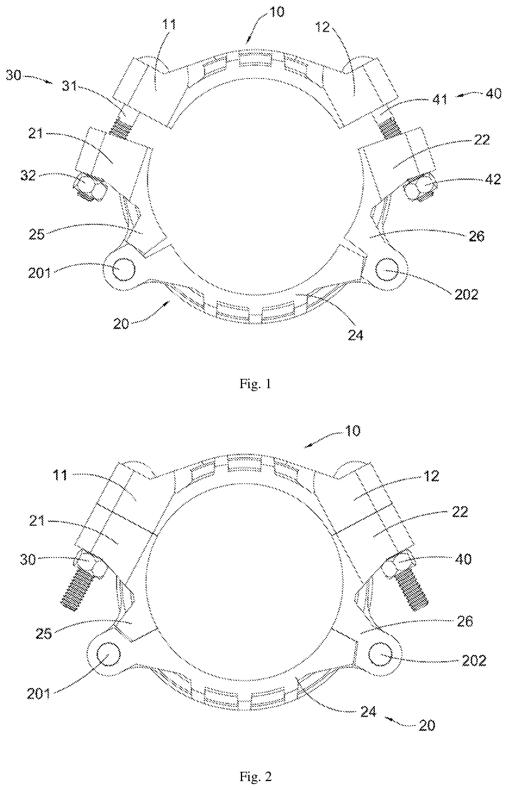
is a front schematic diagram of a first preferred embodiment in the present application in an unfastened state.
is a front schematic diagram of a first preferred embodiment in the present application in a fastened state.
is a front perspective schematic diagram of a first preferred embodiment in the present application.
is a bottom perspective schematic diagram of a first preferred embodiment in the present application.
is an explosion schematic diagram of a first preferred embodiment in the present application.
is a front schematic diagram of a second preferred embodiment in the present application in an unfastened state.
is a front schematic diagram of a second preferred embodiment in the present application in a fastened state.
is a front perspective schematic diagram of a second preferred embodiment in the present application.
is a bottom perspective schematic diagram of a second preferred embodiment in the present application.
is an explosion schematic diagram of a second preferred embodiment in the present application.
is a front schematic diagram of a third preferred embodiment in the present application in an unfastened state.
is a front schematic diagram of a third preferred embodiment in the present application in a fastened state.
is a front perspective schematic diagram of a third preferred embodiment in the present application.
is a bottom perspective schematic diagram of a third preferred embodiment in the present application.
is an explosion schematic diagram of a third preferred embodiment in the present application.
is a front schematic diagram of a fourth preferred embodiment in the present application in an unfastened state.
is a front schematic diagram of a fourth preferred embodiment in the present application in a fastened state.
is a front perspective schematic diagram of a fourth preferred embodiment in the present application.
is a bottom perspective schematic diagram of a fourth preferred embodiment in the present application.
is an explosion schematic diagram of a fourth preferred embodiment in the present application.
is a front schematic diagram of a fifth preferred embodiment in the present application in an unfastened state.
is a front schematic diagram of a fifth preferred embodiment in the present application in a fastened state.
is a front perspective schematic diagram of a fifth preferred embodiment in the present application.
is a bottom perspective schematic diagram of a fifth preferred embodiment in the present application.
is an explosion schematic diagram of a fifth preferred embodiment in the present application.
is a front schematic diagram of a sixth preferred embodiment in the present application in an unfastened state.
is a front schematic diagram of a sixth preferred embodiment in the present application in a fastened state.
is a front perspective schematic diagram of a sixth preferred embodiment in the present application.
is a bottom perspective schematic diagram of a sixth preferred embodiment in the present application.
is an explosion schematic diagram of a sixth preferred embodiment in the present application.
is a front schematic diagram of a seventh preferred embodiment in the present application in an unfastened state.
is a front schematic diagram of a seventh preferred embodiment in the present application in a fastened state.
is a front perspective schematic diagram of a seventh preferred embodiment in the present application.
is a bottom perspective schematic diagram of a seventh preferred embodiment in the present application.
is an explosion schematic diagram of a seventh preferred embodiment in the present application.
is a front schematic diagram of an eighth preferred embodiment in the present application in an unfastened state.
is a front schematic diagram of an eighth preferred embodiment in the present application in a fastened state.
is a front perspective schematic diagram of an eighth preferred embodiment in the present application.
is a bottom perspective schematic diagram of an eighth preferred embodiment in the present application.
is an explosion schematic diagram of an eighth preferred embodiment in the present application.
DETAILED DESCRIPTION
The following description is used to disclose the present application so that those skilled in the art can realize the present application. The preferred embodiments in the following description are only for example, and those skilled in the art can think of other obvious modifications. The basic principles of the present application defined in the following description can be applied to other embodiments, modification solutions, improvement solutions, equivalent solutions and other technical solutions within the spirit and scope of the present application.
Those skilled in the art should understand that in the disclosure of the present, the terms for indicating the orientation or the position relationship like “longitudinal”, “transverse”, “upper”, “lower”, “front”, “rear”, “left”, “right”, “vertical”, “horizontal”, “top”, “bottom”, “inner”, “outer” and so on are based on the orientation or the position relationship in the figures, which are only for the convenience of describing the present application and simplifying the description, rather than indicating or implying that the device or element must have a specific orientation, or be constructed and operated in a specific orientation. Therefore, the above terms cannot be understood as a limitation of the present application.
It should be understood that, the term “a” should be understood as “at least one” of “one or more”, that is in an embodiment, the quantity of the element can be one, while in another embodiment, the quantity of this element can be multiple. The term “a” cannot be understood as a limitation of the quantity.
The quick coupler according to the present application includes three main parts: an arc top ring 10 , an arc bottom ring 20 and two fasteners 30 ( 40 ). The top ring 10 may be engaged with the bottom ring 20 to be assembled together. The top ring 10 is further provided with a top ring groove 13 , and the bottom ring 20 is further provided with a bottom ring groove 23 . The fasteners 30 ( 40 ) may be loosely or tightly connected to the top ring 10 and the bottom ring 20 , so that the top ring 10 and the bottom ring 20 can be fixedly connected as a whole to form an annular groove 50 for fixing pipes. In particular, at least one of the top ring 10 and the bottom ring 20 consists of a plurality of movably connected components, so that the quick coupler according to the present application has a certain flexibility in fixing and assembling, which can realize a loose or tight fixation.
illustrate a first preferred embodiment of the present application. In the first preferred embodiment, a quick coupler includes an arc top ring 10 , an arc bottom ring 20 , a left fastener 30 and a right fastener 40 . The top ring 10 may be assembled with the bottom ring 20 as a whole by the left fastener 30 and the right fastener 40 at two sides respectively, as shown in .
The top ring 10 further includes a top ring left fixing head 11 and a top ring right fixing head 12 . In addition, the top ring 10 is provided with a top ring groove 13 on the arc inner side of the top ring 10 . The top ring left fixing head 11 and the top ring right fixing head 12 are positioned on two ends of the top ring 10 respectively. In addition, the top ring left fixing head 11 is provided with a top ring left fixing hole 111 positioned in the middle of the upper end thereof and a top ring left activity groove 112 positioned in the middle of the lower end thereof, and the top ring right fixing head 12 is provided with a top ring right fixing hole 121 positioned in the middle of the upper end thereof and a top ring right activity groove 122 positioned in the middle of the lower end thereof.
The bottom ring 20 further includes a bottom ring left fixing head 21 , a bottom ring right fixing head 22 , an arc bottom ring middle part 24 , an arc bottom ring left part 25 , an arc bottom ring right part 26 , a bottom ring left shaft member 201 and a bottom ring right shaft member 202 . In addition, the bottom ring 20 is provided with a bottom ring groove 23 positioned on the arc inner side of the bottom ring 20 . The bottom ring left part 25 can be movably connected to the bottom ring right part 26 .
The bottom ring left fixing head 21 protrudes from the upper end of the bottom ring left part 25 . The bottom ring right fixing head 22 protrudes from the upper end of the bottom ring right part 26 . The bottom ring left fixing head 21 is provided with a bottom ring left fixing through hole 211 positioned in the middle of the lower end thereof, and a bottom ring left activity groove 212 positioned in the middle of the upper end thereof. The bottom ring right fixing head 22 is provided with a bottom ring right fixing through hole 221 positioned in the middle of the lower end thereof, and a bottom ring right activity groove 222 positioned in the middle of the upper end thereof.
The left fastener 30 can be loosely or tightly connected to the top ring left fixing head 11 and the bottom ring left fixing head 21 . The right fastener 40 can also be loosely or tightly connected to the top ring right fixing head 12 and the bottom ring right fixing head 22 .
The left fastener 30 further includes a left bolt 31 and a left nut 32 . The right fastener 40 further includes a right bolt 41 and a right nut 42 . The left bolt 31 penetrates through the top ring left fixing hole 111 of the top ring left fixing head 11 and the bottom ring left fixing hole 211 of the bottom ring left fixing head 21 . The left nut 32 can be mounted on the lower end of the left bolt 31 loosely or tightly. The right bolt 41 penetrates through the top ring right fixing hole 121 of the top ring right fixing head 12 and the bottom ring right fixing hole 221 of the bottom ring right fixing head 22 . The right nut 42 can be mounted on the lower end of the right bolt 41 loosely or tightly.
The bottom ring middle part 24 further includes a bottom ring left activity base 241 and a bottom ring right activity base 242 , which are positioned on two ends of the bottom ring middle part 24 respectively. In addition, the bottom ring middle part 24 is provided with a bottom ring middle groove 243 positioned on the arc inner side of the bottom ring middle part 24 .
The bottom ring left part 25 further includes a bottom ring left activity head 251 protruding downwards from the lower end. In addition, the bottom ring left part 25 is provided with a bottom ring left groove 252 positioned on the arc inner side of the bottom ring left part 25 . The bottom ring right part 26 further includes a bottom ring right activity head 261 protruding downwards from the lower end, and the bottom ring right part 26 is provided with a bottom ring right groove 262 positioned on the arc inner side of the bottom ring right part 26 .
The bottom ring left shaft member 201 may movably connects the bottom ring left activity head 251 of the bottom ring left part 25 with the bottom ring left activity base 241 of the bottom ring middle part 24 . The bottom ring right shaft member 202 may movably connects the bottom ring right activity head 261 of the bottom ring right part 26 with the bottom ring right activity base 242 of the bottom ring middle part 24 .
Further, both of the bottom ring left activity base 241 and the bottom ring right activity base 242 have a two-pieces structure. The bottom ring left activity base 241 is provided with a bottom ring left activity base connecting hole 2411 . The bottom ring right activity base 242 is provided with a bottom ring right activity base connecting hole 2421 . The bottom ring left activity head 251 and the bottom ring right activity head 261 both have a two-pieces structure. The bottom ring left activity head 251 is provided with a bottom ring left activity head connecting hole 2511 . The bottom ring right activity head 261 is provided with a bottom ring right activity head connecting hole 2611 .
The bottom ring left activity head 251 and the bottom ring left activity base 241 fit together. The bottom ring left shaft member 201 penetrates the bottom ring left rotatable hear connecting hole 2511 of the bottom ring left activity head 251 and the bottom ring left activity base connecting hole 2411 of the bottom ring left activity base 241 , so as to form a moveable connection between the bottom ring left activity head 251 and the bottom ring left activity base 241 .
The bottom ring right activity head 261 and the bottom ring right activity base 242 fit together. The bottom ring right shaft member 202 penetrates the bottom ring right activity head connecting hole 2611 of the bottom ring right activity head 261 and the bottom ring right activity base connecting hole 2421 of the bottom ring right activity base 242 , so as to form a moveable connection between the bottom ring right activity head 261 and the bottom ring right activity base 242 .
shows a first preferred embodiment of the present application in an unfastened state. In the unfastened state, the top ring 10 and the bottom ring 20 are loosely connected together as a whole by the left fastener 30 and the right fastener 40 . At this time, the top ring 10 does not abut against the bottom ring 20 . The bottom ring middle part 24 , the bottom left part 25 and the bottom ring right part 26 of the bottom ring 20 are in an unfastened connection state.
At this time, the left bolt 31 can limitedly move between the top ring left activity groove 112 and the bottom ring left activity groove 212 . The right bolt 41 can limitedly move between the top ring right activity groove 122 and the bottom ring right activity groove 222 . The left nut 32 is mounted on the lowest end of the left bolt 31 , and the right nut 42 is mounted on the lowest end of the right bolt 41 .
shows the first preferred embodiment of the present application in a tight state. In the tight state, the left fastener 30 and the right fastener 40 are fastened. The bottom ring middle part 24 , the bottom ring left part 25 and the bottom ring right part 26 are tightly jointed due to the stress. The bottom ring middle groove 243 of the bottom ring middle part 24 , the bottom ring left groove 252 of the bottom ring left part 25 and the bottom ring right groove 262 of the bottom ring right part 26 are assembled to form the bottom ring groove 23 . The top ring 10 and the bottom ring 20 are tightly joined due to the stress. The top ring groove 13 of the top ring 10 and the bottom ring groove 23 of the bottom ring 20 are assembled to form an annular groove 50 for fixing the pipes.
In the unfastened state, an end of a pipe or tube to be connected is placed in the annular groove 50 . The end of a pipe or tube to be fixed can be fixed in the annular groove 50 tightly by fastening the left fastener 30 and the right fastener 40 , so as to realize the fast fixing of the pipes or the fittings.
illustrate a second preferred embodiment of the present application. The second preferred embodiment is the modification of the first preferred embodiment. The second preferred embodiment of the present application differs in that, the bottom ring left activity base 241 is modified to another bottom ring left activity base 241 A, the bottom ring right activity base 242 is modified to another bottom ring right activity base 242 A, the bottom ring left activity head 251 is modified to another bottom ring left activity head 251 A, and the bottom ring right activity head 261 is modified to another bottom ring right activity head 261 A.
The bottom ring left activity base 241 A is provided with a bottom ring left activity base connecting hole 2411 A, and the bottom ring right activity base 242 A is provided with a bottom ring right activity base connecting hole 2421 A. The bottom ring left activity head 251 A is provided with a bottom ring left activity head connecting through hole 2511 A, and the bottom ring right activity head 261 A is provided with a bottom ring right activity head connecting through hole 2611 A.
The bottom ring left activity base 241 A and the bottom ring right activity base 242 A both have a two-pieces structure. The bottom ring left activity head 251 A is clamped between the two-pieces structure of the bottom ring left activity base 241 A, and the bottom ring right activity head 261 A is clamped between the two-pieces structure of the bottom ring right activity base 242 A. In addition, the bottom ring left shaft member 201 may movably connects the bottom ring left activity base 241 A with the bottom ring left activity head 251 A. The bottom ring right shaft member 202 movably connects the bottom ring right activity base 242 A with the bottom ring right activity head 261 A.
With the modifications of the above components, the second preferred embodiment may realize the same or the similar effect with the first preferred embodiment.
illustrate a third preferred embodiment of the present application. The third preferred embodiment includes an arc top ring 10 B, an arc bottom ring 20 B, a left fastener 30 B and a right fastener 40 B. The top ring 10 B and the bottom ring 20 B can be combined together as a whole by fixing the left fastener 30 B and the right fastener 40 B on two sides respectively, as shown in .
The top ring 10 B further includes a top ring left fixing head 11 B, a top ring right fixing head 12 B, a top ring middle part 14 B, a top ring left part 15 B, a top ring right part 16 B, a top ring left shaft member 101 and a top ring right shaft member 102 . In addition, the top ring 10 B is provided with a top ring groove 13 B on the arc inner side of the top ring 10 B. The top ring left part 15 B and the top ring right part 16 B can be movably connected to the two ends of the top ring middle part 14 B respectively.
The top ring left fixing head 11 B protrudes from the lower end of the top ring left part 15 B. The top ring right fixing head 12 B protrudes from the lower end of the top ring right part 16 B. The top ring left fixing head 11 B is provided with a top ring left fixing through hole 111 B positioned in the middle of the upper end thereof, and a top ring left activity groove 112 B positioned in the middle of the lower end thereof. The top ring right fixing head 12 B is provided with a top ring right fixing through hole 121 B positioned in the middle of the upper end thereof, and a top ring right activity groove 122 B positioned in the middle of the lower end thereof.
The bottom ring 20 B further includes a bottom ring left fixing head 21 B, a bottom ring right fixing head 22 B, a bottom ring middle part 24 B, a bottom ring left part 25 B, a bottom ring right part 26 B, a bottom ring left shaft member 201 and a bottom ring right shaft member 202 . In addition, the bottom ring 20 B is provided with a bottom ring groove 23 B positioned on the arc inner side of the bottom ring 20 B. The bottom ring left part 25 B and the bottom ring right part 26 B can be movably connected to the two ends of the bottom ring middle part 24 B respectively.
The bottom ring left fixing head 21 B protrudes from the upper end of the bottom ring left part 25 B. The bottom ring right fixing head 22 B protrudes from the upper end of the bottom ring right part 26 B. The bottom ring left fixing head 21 B is provided with a bottom ring left fixing through hole 211 B positioned in the middle of the lower end thereof, and a bottom ring left activity groove 212 B positioned in the middle of the upper end thereof. The bottom ring right fixing head 22 B is provided with a bottom ring right fixing through hole 221 B positioned in the middle of the lower end thereof, and a bottom ring right activity groove 222 B positioned in the middle of the upper end thereof.
The left fastener 30 B can be loosely or tightly connected to the top ring left fixing head 11 B and the bottom ring left fixing head 21 B. The right fastener 40 B can also be loosely or tightly connected to the top ring right fixing head 12 B and the bottom ring right fixing head 22 B.
The left fastener 30 B further includes a left bolt 31 B and a left nut 32 B. The right fastener 40 B further includes a right bolt 41 B and a right nut 42 B. The left bolt 31 B penetrates through the top ring left fixing hole 111 B of the top ring left fixing head 11 B and the bottom ring left fixing hole 211 B of the bottom ring left fixing head 21 B. The left nut 32 B can be mounted on the lower end of the left bolt 31 B loosely or tightly. The right bolt 41 B penetrates through the top ring right fixing hole 121 B of the top ring right fixing head 12 B and the bottom ring right fixing hole 221 B of the bottom ring right fixing head 22 B. The right nut 42 B can be mounted on the lower end of the right bolt 41 B loosely or tightly.
The top ring middle part 14 B further includes a top ring left activity base 141 B and a top ring activity base 142 B, which are positioned on two ends of the top ring middle part 14 B respectively. In addition, the top ring middle part 14 B is provided with a top ring middle groove 143 B positioned on the arc inner side of the top ring middle part 14 B.
The top ring left part 15 B further includes a top ring left activity head 151 B protruding upwards from the upper end. In addition, the top ring left part 15 B is provided with a top ring left groove 152 B positioned on the arc inner side of the top ring left part 15 B. The top ring right part 16 B further includes a top ring right activity head 161 B protruding upwards from the upper end, and the top ring right part 16 B is provided with a top ring right groove 162 B positioned on the arc inner side of the top ring right part 16 B.
The top ring left shaft member 101 movably connects the top ring left activity head 151 B of the top ring left part 15 B with the top ring left activity base 141 B of the top ring middle part 14 B. The top ring right shaft member 102 may movably connects the top ring right activity head 161 B of the top ring right part 16 B with the top ring right activity base 142 B of the top ring middle part 14 B.
Further, the top ring left activity base 141 B and the top right activity base 142 B both have a two-pieces structure. The top ring left activity base 141 B is provided with a top ring left activity base connecting hole 1411 B. The top ring right activity base 142 B is provided with a top ring right activity base connecting hole 1421 B. The top ring left activity head 151 B and the top ring right activity head 161 B both have a two-pieces structure. The top ring left activity head 151 B is provided with a top ring left activity head connecting hole 1511 B. The top ring right activity head 161 B is provided with a top ring right activity head connecting hole 1611 B.
The top ring left activity head 151 B and the top ring left activity base 141 B fit together. The top ring left shaft member 101 penetrates the top ring left activity head connecting hole 1511 B of the top ring left activity head 151 B and the top ring left activity base connecting hole 1411 B of the top ring left activity base 141 B, so as to form a moveable connection between the top ring left activity head 151 B and the top ring left activity base 141 B.
The top ring right activity head 161 B and the top ring right activity base 142 B fit together. The top ring right shaft member 102 penetrates the top ring right activity head connecting hole 1611 B of the top ring right activity head 161 B and the top ring right activity base connecting hole 1421 B of the top ring right activity base 142 B, so as to form a moveable connection between the top ring right activity head 161 B and the top ring right activity base 142 B.
The bottom ring middle part 24 B further includes a bottom ring left activity base 241 B and a bottom ring right activity base 242 B, which are positioned on two ends of the bottom ring middle part 24 B respectively. The bottom ring middle part 24 B is provided with a bottom ring middle groove 243 B on the arc inner side of the bottom ring middle part 24 B.
The bottom ring left part 25 B further includes a bottom ring left activity head 251 B protruding downwards from the lower end. In addition, the bottom ring left part 25 B is provided with a bottom ring left groove 252 B positioned on the arc inner side of the bottom ring left part 25 B. The bottom ring right part 26 B further includes a bottom ring right activity head 261 B protruding downwards from the lower end, and the bottom ring right part 26 B is provided with a bottom ring right groove 262 B positioned on the arc inner side of the bottom ring right part 26 B.
The bottom ring left shaft member 201 may movably connects the bottom ring left activity head 251 B of the bottom ring left part 25 B with the bottom ring left activity base 241 B of the bottom ring middle part 24 B. The bottom ring right shaft member 202 may movably connects the bottom ring right activity head 261 B of the bottom ring right part 26 B with the bottom ring right activity base 242 B of the bottom ring middle part 24 B.
Further, the bottom ring left activity base 241 B and the bottom ring right activity base 242 B both have a two-pieces structure. The bottom ring left activity base 241 B is provided with a bottom ring left activity base connecting hole 2411 B. The bottom ring right activity base 242 B is provided with a bottom ring right activity base connecting hole 2421 B. The bottom ring left activity head 251 B and the bottom right activity head 261 B both have a two-pieces structure. The bottom ring left activity head 251 B is provided with a bottom ring left activity head connecting hole 2511 B. The bottom ring right activity head 261 B is provided with a bottom ring right activity head connecting hole 2611 B.
The bottom ring left activity head 251 B and the bottom ring left activity base 241 B fit together. The bottom ring left shaft member 201 penetrates the bottom ring left rotatable hear connecting hole 2511 B of the bottom ring left activity head 251 B and the bottom ring left activity base connecting hole 2411 B of the bottom ring left activity base 241 B, so as to form a moveable connection between the bottom ring left activity head 251 B and the bottom ring left activity base 241 B.
The bottom ring right activity head 261 B and the bottom ring right activity base 242 B fit together. The bottom ring right shaft member 202 penetrates the bottom ring right activity head connecting hole 2611 B of the bottom ring right activity head 261 B and the bottom ring right activity base connecting hole 2421 B of the bottom ring right activity base 242 B, so as to form a moveable connection between the bottom ring right activity head 261 B and the bottom ring right activity base 242 B.
shows the third preferred embodiment of the present application in an unfastened state. In the unfastened state, the top ring 10 B and the bottom ring 20 B are loosely connected together as a whole by the left fastener 30 B and the right fastener 40 B. At this time, the top ring middle part 14 B, the top ring left part 15 B and the top ring right part 16 B of the top ring 10 B are in an unfastened connection state. The bottom ring middle part 24 B, the bottom left part 25 B and the bottom ring right part 26 B of the bottom ring 20 B are in an unfastened connection state.
As shown in , when fastening the left fastener 30 B and the right fastener 40 B, the top ring middle part 14 B, the top ring left part 15 B and the top ring right part 16 B of the top ring 10 B are tightly jointed due to the stress. The bottom ring middle part 24 B, the bottom ring left part 25 B and the bottom ring right part 26 B of the bottom ring 20 B are tightly jointed due to the stress. In addition, the top ring left fixing head 11 B of the top ring 10 B and the bottom ring left fixing head 21 B of the bottom ring 20 B are tightly jointed due to the stress. The top ring right fixing head 12 B of the top ring 10 B and the bottom ring right fixing head 22 B of the bottom ring 20 B are tightly joint due to the stress, so that the top ring 10 B and the bottom ring 20 B can by tightly jointed together as a whole.
In addition, the top ring middle groove 143 B of the top ring middle part 14 B, the top ring left groove 152 B of the top ring left part 15 B and the top ring right groove 162 B of the top ring right part 16 B are assembled to form the top ring groove 13 B of the top ring 10 B. The bottom ring middle groove 243 B of the bottom ring middle part 24 B, the bottom ring left groove 252 B of the bottom ring left part 25 B and the bottom ring right groove 262 B of the bottom ring right part 26 B are assembled to form the bottom ring groove 23 B of the bottom ring 20 B. Further, the top ring groove 13 B of the top ring 10 B and the bottom ring groove 23 B of the bottom ring 20 B are assembled to form an annular groove 50 B for fixing the end of the pipes to be fixed.
illustrate a fourth preferred embodiment of the present application. The fourth preferred embodiment is the modification of the third preferred embodiment. In the fourth preferred embodiment of the present application, the components in the above third preferred embodiment are modified.
The top ring left activity base 141 B is modified to another top ring left activity base 141 C, the top ring right activity base 142 B is modified to another top ring right activity base 142 C, the top ring left activity head 151 B is modified to another top ring left activity head 151 C, and the top ring right activity head 161 B is modified to another top ring right activity head 161 C.
The bottom ring left activity base 241 B is modified to another bottom ring left activity base 241 C, the bottom ring right activity base 242 B is modified to another bottom ring right activity base 242 C, the bottom ring left activity head 251 B is modified to another bottom ring left activity head 251 C, and the bottom ring right activity head 261 B is modified to another bottom ring right activity head 261 C.
The top ring left activity base 141 C is a two-pieces structure and is provided with a top ring left activity base connecting hole 1411 C. The top ring right activity base 142 C is a two-pieces structure and is provided with a top ring right activity base connecting hole 1421 C. The bottom ring left activity base 241 C is a two-pieces structure and is provided with a bottom ring left activity base connecting hole 2411 C. The bottom ring right activity base 242 C is a two-pieces structure and is provided with a bottom ring right activity base connecting hole 2421 C.
The top ring left activity head 151 C is provided a top ring left activity head connecting through hole 1511 C. The top ring right activity head 161 C is provided with a top ring right activity head connecting through hole 1611 C. The bottom ring left activity head 251 C is provided a bottom ring left activity head connecting through hole 2511 C. The bottom ring right activity head 261 C is provided with a bottom ring right activity head connecting through hole 2611 C.
The top ring left activity head 151 C is clamped in the top ring left activity base 141 C, and form a moveable connection by mounting the top ring left shaft member 101 in the top ring left activity head connecting hole 1511 C and the top ring left activity base connecting hole 1411 C. The top ring right activity head 161 C is clamped in the top ring right activity base 142 C, and form a moveable connection by mounting the top ring right shaft member 102 in the top ring right activity head connecting hole 1611 C and the top ring right activity base connecting hole 1421 C.
The bottom ring left activity head 251 C is clamped in the bottom ring left activity base 241 C, and form a moveable connection by mounting the bottom ring left shaft member 201 in the bottom ring left activity head connecting hole 2511 C and the bottom ring left activity base connecting hole 2411 C. The bottom ring right activity head 261 C is clamped in the bottom ring right activity base 242 C, and form a moveable connection by mounting the bottom ring right shaft member 202 in the bottom ring right activity head connecting hole 2611 C and the bottom ring right activity base connecting hole 2421 C.
With the modifications of the above components, the fourth preferred embodiment may realize the same or the similar effect with the third preferred embodiment.
illustrate a fifth preferred embodiment of the present application. The fifth preferred embodiment includes an arc top ring 10 D, an arc bottom ring 20 D, a left fastener 30 D and a right fastener 40 D. The top ring 10 D and the bottom ring 20 D can be combined together as a whole by fixing the left fastener 30 D and the right fastener 40 D on two sides respectively, as shown in .
The top ring 10 D further includes a top ring left fixing head 11 D and a top ring right fixing head 12 D. The top ring 10 D is provided with a top ring groove 13 D on the arc inner side of the top ring 10 D. The top ring left fixing head 11 D and the top ring right fixing head 12 D are on two ends of the top ring 10 D respectively. The top ring left fixing head 11 D is provided with a top ring left fixing through hole 111 D in the middle of the upper end thereof and a top ring left activity groove 112 D in the middle of the lower end thereof. The top ring right fixing head 12 D is provided with a top ring right fixing through hole 121 D in the middle of the upper end thereof and a top ring right activity groove 122 D in the middle of the lower end thereof.
The bottom ring 20 D further includes a bottom ring left fixing head 21 D, a bottom ring right fixing head 22 D, an arc bottom ring left part 25 D, an arc bottom ring right part 26 D and a bottom ring middle shaft member 203 . In addition, the bottom ring 20 D is provided with a bottom ring groove 23 D on the arc inner side of the bottom ring 20 D. The bottom ring left part 25 D is movably connected to the bottom ring right part 26 D.
The bottom ring left fixing head 21 D protrudes from the upper end of the bottom ring left part 25 D. The bottom ring right fixing head 22 D protrudes from the upper end of the bottom ring right part 26 D. The bottom ring left fixing head 21 D is provided with a bottom ring left fixing through hole 211 D positioned in the middle of the lower end thereof, and a bottom ring left activity groove 212 D positioned in the middle of the upper end thereof. The bottom ring right fixing head 22 D is provided with a bottom ring right fixing through hole 221 D positioned in the middle of the lower end thereof, and a bottom ring right activity groove 222 D positioned in the middle of the upper end thereof.
The left fastener 30 D can be loosely or tightly connected to the top ring left fixing head 11 D and the bottom ring left fixing head 21 D. The right fastener 40 D can also be loosely or tightly connected to the top ring right fixing head 12 D and the bottom ring right fixing head 22 D.
The left fastener 30 D further includes a left bolt 31 D and a left nut 32 D. The right fastener 40 D further includes a right bolt 41 D and a right nut 42 D. The left bolt 31 D penetrates through the top ring left fixing hole 111 D of the top ring left fixing head 11 D and the bottom ring left fixing hole 211 D of the bottom ring left fixing head 21 D. The left nut 32 D can be mounted on the lower end of the left bolt 31 D loosely or tightly. The right bolt 41 D penetrates through the top ring right fixing hole 121 D of the top ring right fixing head 12 D and the bottom ring right fixing hole 221 D of the bottom ring right fixing head 22 D. The right nut 42 D can be mounted on the lower end of the right bolt 41 D loosely or tightly.
The bottom ring left part 25 D further includes a bottom ring left activity head 251 D protruding downwards from the lower end. In addition, the bottom ring left part 25 D is provided with a bottom ring left groove 252 D positioned on the arc inner side of the bottom ring left part 25 D. The bottom ring right part 26 D further includes a bottom ring right activity head 261 D protruding downwards from the lower end, and the bottom ring right part 26 D is provided with a bottom ring right groove 262 D positioned on the arc inner side of the bottom ring right part 26 D.
Further, the bottom ring left activity head 251 D and the bottom ring right activity head 261 D are a spaced embedded structure pair, that is, the bottom ring left activity head 251 D and the bottom ring right activity head 261 D can embedded with each other. The bottom ring left activity head 215 D is provided with a bottom ring left activity head connecting hole 2511 D. The bottom ring right activity head 261 D is provided with a bottom ring right activity head connecting hole 2611 D. By mounting the bottom ring middle shaft member 203 in the bottom ring left activity head connecting hole 2511 D of the bottom ring left activity head 251 D and the bottom ring right activity head connecting hole 2611 D of the bottom ring right activity head 261 D, the bottom ring left activity head 251 D of the bottom ring left part 25 D and the bottom ring right activity head 261 D of the bottom ring right part 26 D form a moveable connection.
shows the fifth preferred embodiment of the present application in an unfastened state. In the unfastened state, the top ring 10 D and the bottom ring 20 D are loosely connected together as a whole by the left fastener 30 D and the right fastener 40 D. At this time, the top ring 10 D does not abut to the bottom ring 20 D. The bottom left part 25 D and the bottom ring right part 26 D of the bottom ring 20 D are in an unfastened connection state.
At this time, the left bolt 31 D can limitedly move between the top ring left activity groove 112 D and the bottom ring left activity groove 212 D. The right bolt 41 D can limitedly move between the top ring right activity groove 122 D and the bottom ring right activity groove 222 D. The left nut 32 D is mounted on the lowest end of the left bolt 31 D, and the right nut 42 D is mounted on the lowest end of the right bolt 41 D.
shows the fifth preferred embodiment of the present application in a tight state. In the tight state, the left fastener 30 D and the right fastener 40 D are fastened. The bottom ring left part 25 D and the bottom ring right part 26 D are tightly jointed due to the stress. The bottom ring left groove 252 D of the bottom ring left part 25 D and the bottom ring right groove 262 D of the bottom ring right part 26 D are assembled to form the bottom ring groove 23 D. The top ring 10 D and the bottom ring 20 D are tightly joined due to the stress. The top ring groove 13 D of the top ring 10 D and the bottom ring groove 23 D of the bottom ring 20 D are assembled to form an annular groove 50 D for fixing the pipes.
In the unfastened state, an end of a pipe or tube to be connected is placed in the annular groove 50 D. The end of a pipe or tube to be fixed can be fixed in the annular groove 50 D tightly by fastening the left fastener 30 D and the right fastener 40 D, so as to realize the fast fixing of the pipes or the fittings.
illustrate a sixth preferred embodiment of the present application. In the sixth preferred embodiment of the present application, the components in the above fifth preferred embodiment are modified.
The bottom ring left activity head 251 D is modified to another bottom ring left activity head 251 E, and the bottom ring right activity head 261 D is modified to another bottom ring right activity head 261 E. The bottom ring left activity head 251 E is a two-pieces structure, and the bottom ring right activity head 261 E is clamped in the bottom ring left activity head 251 D. The bottom ring left activity head 251 E further provides with a bottom ring left activity head connecting hole 2511 E, and the bottom ring right activity head 261 E further provides with a bottom ring right activity head connecting hole 2611 E. By mounting the bottom ring middle shaft member 203 in the bottom ring left activity head connecting hole 2511 E of the bottom ring left activity head 251 E and the bottom ring right activity head connecting hole 2611 E of the bottom ring right activity head 261 E. The bottom ring left activity head 251 E and the bottom ring right activity head 261 E form a moveable connection.
With the modifications of the above components, the sixth preferred embodiment may realize the same or the similar effect with the fifth preferred embodiment.
illustrate a seventh preferred embodiment of the present application. The seventh preferred embodiment includes an arc top ring 10 F, an arc bottom ring 20 F, a left fastener 30 F and a right fastener 40 F. The top ring 10 F and the bottom ring 20 F can be combined together as a whole by fixing the left fastener 30 F and the right fastener 40 F on two sides respectively, as shown in .
The top ring 10 F further includes a top ring left fixing head 11 F, a top ring right fixing head 12 F, a top ring left part 15 F, a top ring right part 16 F and a top ring middle shaft member 103 . In addition, the top ring 10 F is provided with a top ring groove 13 F on the arc inner side of the top ring 10 F. The top ring left part 15 F is movably connected to the top ring right part 16 F.
The top ring left fixing head 11 F protrudes from the lower end of the top ring left part 15 F. The top ring right fixing head 12 F protrudes from the lower end of the top ring right part 16 F. The top ring left fixing head 11 F is provided with a top ring left fixing through hole 111 F positioned in the middle of the upper end thereof, and a top ring left activity groove 112 F positioned in the middle of the lower end thereof. The top ring right fixing head 12 F is provided with a top ring right fixing through hole 121 F positioned in the middle of the upper end thereof, and a top ring right activity groove 122 F positioned in the middle of the lower end thereof.
The bottom ring 20 F further includes a bottom ring left fixing head 21 F, a bottom ring right fixing head 22 F, an arc bottom ring left part 25 F, an arc bottom ring right part 26 F and a bottom ring middle shaft member 203 . The bottom ring 20 F is provided with a bottom ring groove 23 F on the arc inner side of the bottom ring 20 F. The bottom ring left part 25 F is movably connected to the bottom ring right part 26 F.
The bottom ring left fixing head 21 F protrudes from the upper end of the bottom ring left part 25 F. The bottom ring right fixing head 22 F protrudes from the upper end of the bottom ring right part 26 F. The bottom ring left fixing head 21 F is provided with a bottom ring left fixing through hole 211 F positioned in the middle of the lower end thereof, and a bottom ring left activity groove 212 F positioned in the middle of the upper end thereof. The bottom ring right fixing head 22 F is provided with a bottom ring right fixing through hole 221 F positioned in the middle of the lower end thereof, and a bottom ring right activity groove 222 F positioned in the middle of the upper end thereof.
The left fastener 30 F can be loosely or tightly connected to the top ring left fixing head 11 F and the bottom ring left fixing head 21 F. The right fastener 40 F can also be loosely or tightly connected to the top ring right fixing head 12 F and the bottom ring right fixing head 22 F.
The left fastener 30 F further includes a left bolt 31 F and a left nut 32 F. The right fastener 40 F further includes a right bolt 41 F and a right nut 42 F. The left bolt 31 F penetrates through the top ring left fixing hole 111 F of the top ring left fixing head 11 F and the bottom ring left fixing hole 211 F of the bottom ring left fixing head 21 F. The left nut 32 F can be mounted on the lower end of the left bolt 31 F loosely or tightly. The right bolt 41 F penetrates through the top ring right fixing hole 121 F of the top ring right fixing head 12 F and the bottom ring right fixing hole 221 F of the bottom ring right fixing head 22 F. The right nut 42 F can be mounted on the lower end of the right bolt 41 F loosely or tightly.
The top ring left part 15 F further includes a top ring left activity head 151 F protruding upwards from the upper end. In addition, the top ring left part 15 F is provided with a top ring left groove 152 F positioned on the arc inner side of the top ring left part 15 F. The top ring right part 16 F further includes a top ring right activity head 161 F protruding upwards from the upper end, and the top ring right part 16 F is provided with a top ring right groove 162 F positioned on the arc inner side of the top ring right part 16 F.
Further, the top ring left activity head 151 F and the top ring right activity head 161 F are a spaced embedded structure pair, that is, the top ring left activity head 151 F and the top ring right activity head 161 F can embedded with each other. The top ring left activity head 115 F is provided with a top ring left activity head connecting hole 1511 F. The top ring right activity head 161 F is provided with a top ring right activity head connecting hole 1611 F. By mounting the top ring middle shaft member 103 in the top ring left activity head connecting hole 1511 F of the top ring left activity head 151 F and the top ring activity head connecting hole 1611 F of the top ring right activity head 161 F, the top ring left activity head 151 F of the top ring left part 15 F and the top ring right activity head 161 F of the top ring right part 16 F form a moveable connection.
The bottom ring left part 25 F further includes a bottom ring left activity head 251 F protruding downwards from the lower end. In addition, the bottom ring left part 25 F is provided with a bottom ring left groove 252 F positioned on the arc inner side of the bottom ring left part 25 F. The bottom ring right part 26 F further includes a bottom ring right activity head 261 F protruding downwards from the lower end, and the bottom ring right part 26 F is provided with a bottom ring right groove 262 F positioned on the arc inner side of the bottom ring right part 26 F.
Further, the bottom ring left activity head 251 F and the bottom ring right activity head 261 F are a spaced embedded structure pair, that is, the bottom ring left activity head 251 F and the bottom ring right activity head 261 F can embedded with each other. The bottom ring left activity head 215 F is provided with a bottom ring left activity head connecting hole 2511 F. The bottom ring right activity head 261 F is provided with a bottom ring right activity head connecting hole 2611 F. By mounting the bottom ring middle shaft member 203 in the bottom ring left activity head connecting hole 2511 F of the bottom ring left activity head 251 F and the bottom ring right activity head connecting hole 2611 F of the bottom ring right activity head 261 F, the bottom ring left activity head 251 F of the bottom ring left part 25 F and the bottom ring right activity head 261 F of the bottom ring right part 26 F form a moveable connection.
shows the seventh preferred embodiment of the present application in an unfastened state. In the unfastened state, the top ring 10 F and the bottom ring 20 F are loosely connected together as a whole by the left fastener 30 F and the right fastener 40 F. At this time, the top ring 10 F does not abut to the bottom ring 20 F. The top left part 15 F and the top ring right part 16 F of the bottom ring 20 D are in an unfastened connection state, and the bottom ring left part 25 F and the bottom ring right part 26 F of the bottom ring 20 F are in an unfastened connection state.
At this time, the left bolt 31 F can limitedly move between the top ring left activity groove 112 F and the bottom ring left activity groove 212 F. The right bolt 41 F can limitedly move between the top ring right activity groove 122 F and the bottom ring right activity groove 222 F. The left nut 32 F is mounted on the lowest end of the left bolt 31 F, and the right nut 42 F is mounted on the lowest end of the right bolt 41 F.
shows the seventh preferred embodiment of the present application in a tight state. In the tight state, the left fastener 30 F and the right fastener 40 F are fastened. The top ring left part 15 F and the top ring right part 16 F are tightly jointed due to the stress. The top ring left groove 152 F of the top ring left part 15 F and the top ring right groove 162 F of the top ring right part 16 F are assembled to form the top ring groove 13 F. The bottom ring left part 25 F and the bottom ring right part 26 F are tightly jointed due to the stress. The bottom ring left groove 252 F of the bottom ring left part 25 F and the bottom ring right groove 262 F of the bottom ring right part 26 F are assembled to form the bottom ring groove 23 F. The top ring 10 F and the bottom ring 20 F are tightly joined due to the stress. The top ring groove 13 F of the top ring 10 F and the bottom ring groove 23 F of the bottom ring 20 F are assembled to form an annular groove 50 F for fixing the pipes or fittings.
In the unfastened state, the end of the connecting pipe or the fitting is placed in the annular groove 50 F. The end of the to-be-fixed pipe or fixing can be fixed in the annular groove 50 F tightly by fastening the left fastener 30 F and the right fastener 40 F, so as to realize the fast fixing of the pipes or the fittings.
illustrate an eighth preferred embodiment of the present application. In the eighth preferred embodiment of the present application, the components in the above seventh preferred embodiment are modified.
The top ring left activity head 151 F is modified to another top ring left activity head 151 G, and the top ring right activity head 161 F is modified to another top ring right activity head 161 G. The top ring right activity head 161 G is a two-pieces structure, and the top ring left activity head 151 G is clamped in the top ring right activity head 161 G. The top ring left activity head 151 G further provides with a top ring left activity head connecting hole 1511 G, and the top ring right activity head 161 G further provides with a top ring right activity head connecting hole 1611 G. By mounting the top ring middle shaft member 103 in the top ring left activity head connecting hole 1511 G of the top ring left activity head 151 G and the top ring right activity head connecting hole 1611 G of the top ring right activity head 161 G. The top ring left activity head 151 G and the top ring right activity head 161 G form a moveable connection.
The bottom ring left activity head 251 F is modified to another bottom ring left activity head 251 G, and the bottom ring right activity head 261 F is modified to another bottom ring right activity head 261 G. The bottom ring right activity head 261 G is a two-pieces structure, and the bottom ring left activity head 251 G is clamped in the bottom ring right activity head 261 G. The bottom ring left activity head 251 G further provides with a bottom ring left activity head connecting hole 2511 G, and the bottom ring right activity head 261 G further provides with a bottom ring right activity head connecting hole 2611 G. By mounting the bottom ring middle shaft member 203 in the bottom ring left activity head connecting hole 2511 G of the bottom ring left activity head 251 G and the bottom ring right activity head connecting hole 2611 G of the bottom ring right activity head 261 G. The bottom ring left activity head 251 G and the bottom ring right activity head 261 G form a moveable connection.
With the modifications of the above components, the eighth preferred embodiment may realize the same or the similar effect with the seventh preferred embodiment.
Since the present application has described multiple embodiments, it is not intended to limit the present application to the above embodiments. Without departing from the above principles, the embodiments of the present application may have any deformation or modification, including but not limited to replacing materials, modifying structure, changing appearance, adjusting size, etc., and these deformations should be included in the spirit of the present application.
Figures (20)
Citations
This patent cites (52)
- US2923561
- US3464722
- US3600770
- US3661409
- US3764170
- US4191410
- US4225160
- US4341406
- US4408788
- US4488744
- US4781406
- US4915418
- US5707089
- US6499773
- US7341287
- US10711929
- US10797372
- US11808388
- US2005/0212296
- US2011/0154646
- US2013/0185919
- US2014/0132000
- US2014/0333062
- US2015/0176728
- US2020/0049285
- US2020/0332934
- US2022/0186862
- US2161799
- US201582505
- US102644811
- US202629425
- US103867829
- US105508761
- US105508762
- US206377375
- US207864855
- US112212092
- US113757461
- US2100568
- US102008058373
- US0406597
- US2550960
- US202000009817
- USS5028638
- USS5973694
- US2019525093
- US200379822
- US20110046903
- US101366184
- US101810507
- USWO-2009102698
- USWO-2020045749