Abstract
A filling nozzle includes a pipe joint body provided at a tip of a filling hose and connected to a receptacle on a side to be filled; a clutch that extends on an outside of the pipe joint body in a connection direction in which the pipe joint body and the receptacle are connected and engages with the receptacle; a lever that extends on an outside of the clutch in the connection direction and restricts a movement of the clutch in the connection direction when the gaseous fuel is filled; and an urging means urging the clutch inward in a direction perpendicular to the connection direction to release the restriction in movement of the clutch in the connection direction when filling of the gaseous fuel is completed.
Claims (9)
1 . A filling nozzle comprising: a pipe joint body provided at a tip of a filling hose for filling gaseous fuel and detachably connectable to a receptacle on a side to be filled with gaseous fuel; a clutch that extends on an outside of the pipe joint body in a connection direction defined by the direction in which the pipe joint body and the receptacle are connected and engages with the receptacle; a lever that extends on an outside of the clutch in the connection direction and restricts a movement of the clutch in the connection direction when the gaseous fuel is filled; and a biasing body spaced from the lever and interposed between the lever and the clutch or between the pipe joint body and the clutch, said biasing body urging the clutch inward in a direction perpendicular to the connection direction to release the restriction in movement of the clutch in the connection direction when filling of the gaseous fuel is completed.
Show 8 dependent claims
2 . The filling nozzle as claimed in claim 1 , wherein said biasing body is an elastic body disposed between the lever and the clutch.
3 . The filling nozzle as claimed in claim 1 , wherein said biasing body is a ring-shaped elastic spacer disposed at an engaging portion where an end, remote from the receptacle, of the clutch engages with the pipe joint body, and a shape of said elastic spacer is complementary to a region of the engaging portion inward in a direction perpendicular to the connection direction.
4 . The filling nozzle as claimed in claim 1 , wherein an annular recess for accommodating the end, remote from the receptacle, of the clutch is formed in the pipe joint body, and a drainage channel is provided for communicating the annular recess with an outside of the pipe joint body.
5 . The filling nozzle as claimed in claim 2 , wherein said biasing body is a ring-shaped elastic spacer disposed at an engaging portion where an end, remote from the receptacle, of the clutch engages with the pipe joint body, and a shape of said elastic spacer is complementary to a region of the engaging portion inward in a direction perpendicular to the connection direction.
6 . The filling nozzle as claimed in claim 2 , wherein an annular recess for accommodating the end, remote from the receptacle, of the clutch is formed in the pipe joint body, and a drainage channel is provided for communicating the annular recess with an outside of the pipe joint body.
7 . The filling nozzle as claimed in claim 3 , wherein an annular recess for accommodating the end, remote from the receptacle, of the clutch is formed in the pipe joint body, and a drainage channel is provided for communicating the annular recess with an outside of the pipe joint body.
8 . The filling nozzle as claimed in claim 1 , wherein the biasing body is configured to move in concert with the clutch.
9 . The filling nozzle as claimed in claim 1 , wherein the biasing body is configured to apply an inwardly biasing force on the clutch when the pipe joint body is disconnected from the receptacle.
Full Description
Show full text →
CROSS-REFERENCE TO RELATED APPLICATIONS
The present application claims priority to Japanese Patent Application No. 2023-080562 filed on May 16, 2023, the disclosure of which is incorporated herein by reference.
STATEMENT RE: FEDERALLY SPONSORED RESEARCH/DEVELOPMENT
Not Applicable
BACKGROUND
1. Field of the Invention
The present invention relates to a filling nozzle for filling gaseous fuel such as hydrogen gas.
2. Description of the Related Art
Regarding a filling nozzle for filling gaseous fuel, in order to prevent deterioration of seal structures and reduce the possibility of hydrogen gas leakage, the applicant proposed a technique disclosed in JP-B-6516207. Although this technique is useful, in a state where a filling nozzle and a receptacle are connected, a protrusion formed at a tip of a clutch of the filling nozzle becomes unable to move radially inward due to freezing or the like, and if the filling nozzle is fixed in a radially outwardly open state, there is a problem in that the filling nozzle cannot be removed from the receptacle.
The content of JP-B-6516207 gazette is incorporated herein by reference in its entirety.
BRIEF SUMMARY
The present invention has been proposed in view of the problems of the prior art described above, and an object thereof is to provide a filling nozzle that can be disconnected from a receptacle even if a clutch becomes difficult to disengage.
A filling nozzle 10 according to the present invention is characterized by including: a pipe joint body 1 provided at a tip of a filling hose for filling gaseous fuel and connected to a receptacle 20 on a side to be filled with gaseous fuel; a clutch 4 that extends on an outside of the pipe joint body 1 in a direction in which the pipe joint body 1 and the receptacle 20 are connected (hereinafter referred to as “connection direction”) and engages with the receptacle 20 ; a lever 5 that extends on an outside of the clutch 4 in the connection direction and restricts a movement of the clutch 4 in the connection direction when the gaseous fuel is filled; and an urging means interposed between the lever 5 and the clutch 4 or between the pipe joint body 1 and the clutch 4 , the urging means urging the clutch 4 inward in a direction perpendicular to the connection direction to release the restriction in movement of the clutch 4 in the connection direction when filling of the gaseous fuel is completed.
Here, the urging means may be an elastic body 14 such as a spring disposed between the lever 5 and the clutch 4 .
In addition, the urging means can be a ring-shaped elastic spacer 15 disposed at an engaging portion 4 EE where an end 4 E, remote from the receptacle 20 , of the clutch 4 engages with the pipe joint body 1 , and a shape of the elastic spacer 15 is complementary to a region of the engaging portion 4 EE inward in a direction perpendicular to the connection direction.
Further, an annular recess 1 D for accommodating the end, remote from the receptacle 20 , of the clutch 4 may be formed in the pipe joint body 1 , and a drainage channel 7 W can be provided for communicating the annular recess 1 D with an outside of the pipe joint body 1 .
According to the filling nozzle of the present invention having the above-described configuration, since the filling nozzle 10 includes the urging means for releasing the restriction in movement of the clutch 4 in the connection direction when gaseous fuel filling is completed, even if it becomes difficult for the clutch 4 to be disengaged for some reason, the filling nozzle 10 can be disconnected from the receptacle 20 .
Here, for example, when moisture contained in the air that has entered the filling nozzle 10 is cooled by a low temperature hydrogen gas, it freezes and connects the clutch 4 and the nozzle parts around it, or the elastic body 14 such as a spring and the nozzle parts of the clutch 4 on an outer side in the connection direction may be coupled together. When a water accumulated in an annular recess 1 D of the pipe joint body 1 freezes, the clutch 4 cannot be removed from the receptacle 20 , and the filling nozzle 10 cannot be disconnected from the receptacle 20 .
However, in the present invention, if the drainage channel 7 W is provided that communicates the annular recess (groove) 1 D that accommodates the end 4 E of the clutch 4 formed in the pipe joint body 1 with an outside of the pipe joint body 1 , even if a water accumulates in the recess 1 D, it is discharged to the outside of the filling nozzles 10 - 1 and 10 - 2 via the drainage channel 7 W, so that freezing of the annular recess 1 D can be prevented. Therefore, the inward movement of the clutch 4 in the direction perpendicular to the connection direction is not hindered, and the clutch 4 is disengaged from the receptacle 20 , and the filling nozzles 10 - 1 and 10 - 2 can be disconnected from the receptacle 20 .
Further, the urging means is the ring-shaped elastic spacer 15 disposed in the engagement portion 4 EE whose end portion of the clutch 4 on the side away from the receptacle 20 is engaged with the pipe joint body 1 , and making the shape of the engagement portion 4 EE complementary to the inner region in the direction perpendicular to the connection direction, water and foreign matter do not enter the region. Further, the end portion 4 E of the clutch 4 is in contact with the pipe joint body 1 at the engaging portion 4 EE. Therefore, the elastic repulsive force R acting outward in the direction perpendicular to the connection direction of the elastic spacer 15 acts as a rotational force CCW with the engagement portion 4 EE as a rotation center. This rotational force CCW urges the clutch 4 other than the end 4 E inward in the radial direction, so that the clutch 4 is disengaged from the receptacle 20 and the filling nozzle 10 - 2 is disconnected from the receptacle 20 .
BRIEF DESCRIPTION OF THE DRAWINGS
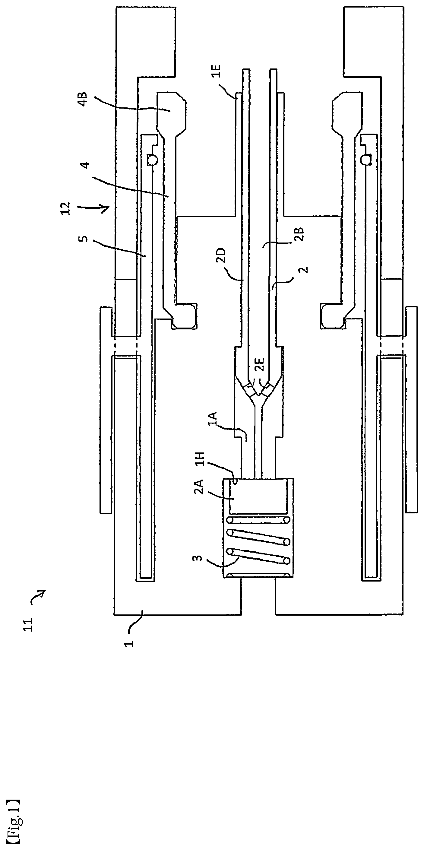
is a sectional view showing a pipe joint body of a conventional filling nozzle.
is a sectional view showing a state in which the pipe joint shown in is coupled to a receptacle.
is an enlarged view of a portion F 3 in .
is a sectional view showing a filling nozzle according to the first embodiment of the present invention.
is an explanatory view showing a spring of the filling nozzle shown in .
is an enlarged view showing an engagement portion between a clutch and a pipe joint of the filling nozzle shown in , with no elastic spacer fitted.
is a partially enlarged sectional view showing essential parts of a filling nozzle according to the second embodiment of the present invention.
is a cross-sectional view schematically showing a drainage channel of the filling nozzle shown in .
is a partially enlarged sectional view showing essential parts of the filling nozzle shown in .
DETAILED DESCRIPTION
Embodiments of the present invention will be described below with reference to the accompanying drawings. First, in order to understand the present invention, the prior art described in JP-B-6516207 will be explained with reference to to 3 .
In , a filling nozzle 11 is provided, for example, at a tip of a filling hose of a fuel filling system that fills hydrogen into a hydrogen filling tank of an FCV, and has a pipe fitting body 1 , which is connected to a receptacle 20 at filling. A pipe joint flow path 1 A is formed inside the pipe joint body 1 , a rod 2 is slidably disposed in the pipe joint flow path 1 A, and a valve seat 1 H is formed. A valve body 2 A is provided at an end of the rod 2 , and is seated on the valve seat 1 H. An elastic member 3 that urges the valve body 2 A toward the valve seat 1 H is disposed in the pipe joint flow path 1 A.
As shown in , when the pipe fitting body 1 and the receptacle 20 are connected, a hydrogen gas flows through the pipe fitting internal flow path 1 A, the rod internal flow path 2 B, or flows through a gap 61 between an outer circumferential surface of a rod large diameter portion 2 D and an inner peripheral surface of the joint internal flow path 1 A, reaches a bottom 20 C of a receptacle fitting recess, and flows through the receptacle internal flow path 20 B. Even if there is a hydrogen gas flowing from the bottom 20 C of the receptacle fitting recess through the gap F 1 between an inner wall surface 20 D of the receptacle fitting recess and an outer peripheral surface of the pipe joint central projection 1 E, the hydrogen gas is sealed by an O-ring 21 provided on the inner peripheral surface 20 D.
In , a clutch mechanism 12 has a function of holding a receptacle side end of the lever 5 at a position radially outward of the clutch 4 and preventing a protrusion 4 B of the clutch 4 from coming off from a fitting groove 20 A of the receptacle 20 . The clutch mechanism 12 includes a protrusion 5 B provided at the end of the lever 5 on the receptacle side (right side in ) so as to protrude radially inward, and a ring-shaped elastic member 6 (for example, an O-ring) provided on a side (left side in ) farther from the receptacle 20 than the protrusion 5 B of the lever. The ring-shaped elastic member 6 fits into an elastic body groove 5 C formed near the receptacle side end of the lever 5 .
As shown in , when the pipe fitting body 1 and the receptacle 20 are connected, the valve body 2 A at a tip of the rod 2 is separated from the valve seat 1 H, and a hydrogen gas flows into the pipe fitting internal flow path 1 A, and flows through the rod internal flow path 2 B and the receptacle internal flow path 20 B. At this time, the hydrogen gas is at a very high pressure (for example, 70 MPa), and this pressure causes a tensile force F 1 ( ) that tries to peel off the pipe joint body 1 from the receptacle 20 . As a result of the tensile force F 1 acting on the pipe joint body 1 , a slope 4 BA of the protrusion 4 B of the clutch 4 on the side away from the receptacle 20 (the left side in ) and a slope 20 AA of the receptacle fitting groove 20 A away from the receptacle 20 cause radially outward force RO, as a component of the tensile force F 1 , to act on the clutch 4 , and this force RO moves the clutch 4 radially outward.
As shown in , which is an enlarged view of a portion F 3 in , when the clutch 4 moves radially outward due to the radially outward force RO, the ring-shaped elastic body 6 becomes collapsed in the radial direction. As a result, the end surface 4 BB of the protrusion 4 B of the clutch 4 and the end surface 5 BA of the protrusion 5 B of the lever 5 are joined in a region FT. As a result, the lever 5 cannot move away from the receptacle 20 from the state shown in (leftward in ). Since the lever 5 does not move, the lever 5 continues to be located radially outward of the protrusion 4 B of the clutch 4 , and prevents the clutch 4 from moving radially outward. Therefore, the protrusion 4 B of the clutch 4 does not come off the fitting groove 20 A of the receptacle 20 , and the connection between the pipe joint body 1 and the receptacle 20 is prevented from being disconnected.
In , when filling with hydrogen gas is completed and predetermined depressurization work is completed, the tensile force F 1 due to the high pressure of hydrogen gas disappears. Along with this, the radially outward force RO acting on the clutch 4 also disappears, the clutch 4 returns to the radially inward position (the position before hydrogen gas filling), and the ring-shaped elastic member 6 returns to the state with a circular cross section from the collapsed state shown in . Therefore, the end surface 4 BB and the end surface 5 BA have different relative positions in the radial direction (vertical positions in ), and are not in a state like the region FT in . Therefore, unlike the state shown in , the lever 5 is movable in the direction away from the receptacle 20 (leftward in ). If the lever 5 is moved in the direction away from the receptacle 20 (to the left in ), the lever 5 will not be located radially outward of the clutch 4 , and the protrusion 4 B can deviate from the fitting groove 20 A of the receptacle 20 . Then, the connection between the pipe joint body 1 and the receptacle 20 can be released.
The invention described in JP-B-6516207 with reference to to 3 is a useful technique. However, if for some reason the connection between the end surface 4 BB of the protrusion 4 B of the clutch 4 and the end surface 5 BA of the protrusion 5 B of the lever 5 is not released, even if the hydrogen filling is completed and the radially outward force RO disappears, the end surface 4 BB and the end surface 5 BA are not separated, and the lever 5 cannot be moved in the direction away from the receptacle 20 . In that case, the protrusion 4 B of the clutch 4 cannot be removed from the fitting groove 20 A of the receptacle 20 , and the nozzle 11 cannot be removed from the receptacle 20 .
In contrast, in the filling nozzle 10 of the first embodiment shown in , the nozzle 11 can be reliably removed from the receptacle 20 once hydrogen filling is completed and the radially outward force RO disappears. In , a spring (elastic body) 14 is disposed at or near the center of the clutch 4 in the longitudinal direction of the nozzle, and the spring 14 urges the clutch 4 inward in the radial direction of the nozzle 10 . The structure of the portion where the clutch base portion 4 E engages with the distal end portion 1 C of the pipe joint body 1 is different in the first embodiment shown in from that in to 3 . Although the receptacle 20 is not shown in , the structure on the receptacle side is the same as in to 3 . In , the left side is the receptacle side. When explaining with reference to , parts similar to those in to 3 are given the same reference numerals as in to 3 , and redundant explanation will not be given. In the following, points different from those in to 3 will be mainly explained.
In , a convex portion 4 C is formed near the center of the clutch 4 in the longitudinal direction of the filling nozzle. A groove 4 D is formed radially outward of the convex portion 4 C. The spring 14 , which is an elastic body, is arranged in the groove 4 D. When the spring 14 is disposed in the groove 4 D (see ), it contracts radially inward due to elastic repulsive force, as shown in , for example. This contraction force acts from the spring 14 on the bottom of the groove 4 D, and acts in the direction indicated by an arrow F 5 . The clutch 4 is urged inward in the radial direction of the nozzle 10 by an elastic repulsive force (the arrow F 5 ) by the spring 14 .
In , a locking portion 14 T that protrudes inward in the radial direction of the clutch 4 is provided at an end of the spring 14 , and a hole (not shown) is formed at the bottom of the groove 4 D. By locking the locking portion 14 T in the hole at the bottom of the groove 4 D, the spring 14 can be prevented from rotating in the circumferential direction. Further, a gap 14 S is formed between the end where the locking portion 14 T is provided and the other end 14 E 2 , so that even if the spring 14 is urged inward in the radial direction by an unexpected external force, the damage is prevented by the gap 14 S. Although not shown, the spring 14 may be a tension coil spring connected in an annular shape.
As shown in , the pipe fitting body 1 includes a pipe fitting body base 1 B and a pipe fitting body tip 1 C, and a clutch base 4 E (dispenser side end of the clutch 4 : right end in ) engages with the pipe fitting body tip 1 C at a concave portion 1 D. Details of the engagement portion between the annular recess 1 D of the pipe joint body 1 and the clutch base 4 E are shown in . In , the receptacle side is indicated by an arrow AR, and the dispenser side is indicated by an arrow AD. The dispenser side end 4 E of the clutch 4 is offset radially inward (downward in ) compared to other parts of the clutch 4 . In the dispenser side end 4 E of the clutch 4 , the portion on the receptacle side (left side in ) is an engaging portion 4 EE, and the engaging portion 4 EE is engaged with the pipe joint body 1 . Further, an endmost portion 4 EA located closest to the dispenser (rightmost in ) is located radially outward (upper in ) compared to the engaging portion 4 EE. In the dispenser side end 4 E, a radially inner end surface 4 EB forms an inclined surface facing radially outward (upward in ) toward the dispenser side AD. A radially outer end surface of the dispenser side end 4 E of the clutch 4 has an inclined surface 4 EC and a flat surface 4 ED.
In , at the dispenser side end 4 E, the flat surface 4 ED of the radially outer end surface is movable by the length shown by an arrow A, the outermost end 4 EA is movable by the length shown by an arrow B, and the radially inner end surface 4 EB is movable by a length indicated by an arrow C with respect to the pipe joint body 1 . As described above with reference to , the clutch 4 is radially inwardly biased by the elastic repulsive force of the spring 14 disposed in the groove 4 D formed at or near the longitudinal center of the nozzle of the clutch 4 . The clutch 4 to which the elastic repulsive force acts is not supported anywhere on the receptacle side (the arrow AR side in ), and the end 4 E on the dispenser side can move by the lengths shown by the arrows A, B, and C as described above. Therefore, at the engagement point (recess 1 D: see ) where the dispenser side end 4 E of the clutch 4 is engaged with the pipe joint body tip 1 C, urging the clutch 4 inward in the radial direction of the nozzle 10 by the elastic repulsive force of the spring 14 is not impeded.
In the filling nozzle 10 of the first embodiment shown in , for some reason, even if the end surface 4 BB of the protrusion 4 B of the clutch 4 (see ) and the end surface 5 BA of the protrusion 5 B of the lever 5 (see ) becomes difficult to release, the elastic repulsive force of the spring 14 urges and presses the clutch 4 inward in the radial direction. When hydrogen filling is completed and the radially outward force RO ( ) disappears, the tip of the clutch 4 moves radially inward due to the elastic repulsive force of the spring 14 , and the coupling between the end surface 4 BB of the protrusion 4 B of the clutch 4 and the end surface 5 BA of the protrusion 5 B of the lever 5 is released, and the lever 5 can be moved in a direction away from the receptacle 20 (leftward in ). As a result, the protrusion 4 B of the clutch 4 can be removed from the fitting groove 20 A of the receptacle 20 , and the filling nozzle 10 can be disconnected from the receptacle 20 . In addition, in the first embodiment shown in , the configuration in which the dispenser side end 4 E of the clutch 4 engages with the tip end 1 C of the pipe joint body 1 is not limited to that shown in . For example, it is also possible to adopt the configuration shown in (the configuration described in JP-B-6516207 gazette).
In the first embodiment shown in , for example, when moisture contained in the air that has entered the filling nozzle 10 is cooled by low temperature hydrogen gas, it freezes and connects the clutch 4 and its surrounding nozzle parts. For example, when the pipe joint body 1 of the filling nozzle 10 is connected to the receptacle 20 , if the water accumulated in the annular groove 1 D (the recessed part where the dispenser side end 4 E of the clutch 4 engages) freezes, the elastic repulsive force of the spring 14 makes it impossible for the clutch 4 to move inward in the radial direction, and the protrusion 4 B of the clutch 4 does not come off the fitting groove 20 A ( ) of the receptacle 20 , thereby connecting the filling nozzle 10 from the receptacle 20 will no longer be possible to release it. In the first embodiment shown in , it is difficult to prevent such inconveniences caused by freezing.
This disadvantage is overcome by the second embodiment of the present invention. The second embodiment will be described with reference to . In , the filling nozzle according to the second embodiment is generally designated by the reference numeral 10 - 1 . In , a drainage channel 7 W communicates with the annular recess 1 D formed in the pipe joint body 1 and engaged with the dispenser side end 4 E of the clutch 4 . As shown by a dotted line in , the drainage channel 7 W passes through the pipe joint body 1 , and although it is not clearly shown, the drainage channel 7 W is configured to communicate with a drainage port (not shown) provided at a boundary between a grip of the filling nozzle 10 - 1 and a filling hose to drain from the boundary to the outside of the filling nozzle 10 - 1 . It is also possible to form the drainage port at a location other than the boundary between the grip of the filling nozzle 10 - 1 and the filling hose.
In the second embodiment shown in , even if water accumulates in the annular recess 1 D, the accumulated water is discharged to the outside of the filling nozzle 10 - 1 via the drainage channel 7 W, and freezing is prevented. Therefore, the clutch 4 moves radially inward due to the elastic repulsive force of the spring 14 , making it possible to move the lever 5 in the direction away from the receptacle 20 (leftward in ), and the protrusion 4 B of the clutch 4 comes off from the fitting groove 20 A ( ) of the receptacle 20 , and the filling nozzle 10 can be disconnected from the receptacle 20 . The other configurations and effects of the second embodiment shown in are the same as those of the first embodiment shown in to 6 .
Next, the third embodiment of the present invention will be described with reference to . The filling nozzle according to the third embodiment is generally designated by the reference numeral 10 - 2 . In , an elastic spacer 15 abuts against the engagement portion where the dispenser side end 4 E of the clutch 4 (the end remote from the receptacle 20 , the right end in ) is engaged with the pipe joint body 1 . The elastic repulsive force of the elastic spacer 15 acts on the end 4 E of the clutch 4 , as shown by an arrow 3 . The shape of the elastic spacer 15 is approximately complementary to the radially inner region of the gap of the recess 1 D (the lower region of the recess 1 D in ), and is located in that region. If the elastic spacer 15 is located in a region radially inward (downward in ) from the radially inner end surface 4 EB of the dispenser side end 4 E of the recess 1 D, no water or foreign matter will be present in the region. Further, in the third embodiment shown in , the drainage channel 7 W communicates with the annular recess 1 D similarly to the second embodiment. Therefore, even if water accumulates outside the elastic spacer 15 in the radial direction (above in ), it is discharged to the outside of the filling nozzle 10 - 1 via the drainage channel 7 W.
Here, the end portion 4 E of the clutch 4 is in contact with the pipe joint body 1 at the engaging portion 4 EE at the filling nozzle side (arrow AR side: left side in ) end of the recess 1 D. Therefore, the elastic repulsive force R acting radially outward (upward in ) acts as a rotational force indicated by the arrow CCW with the engagement portion 4 EE as the rotation center. It is also possible to generate a rotational force with a corner indicated by a reference numeral 4 EF in as a rotation center. The rotational force acting in the direction indicated by the arrow CCW becomes a force that moves the receptacle side portion 4 R of the clutch 4 (the portion other than the dispenser side end 4 E of the clutch 4 ) radially inward. This force causes the clutch 4 to move radially inward, the protrusion 4 B of the clutch 4 disengaging from the fitting groove 20 A ( ) of the receptacle 20 , and the filling nozzle 10 being disconnected from the receptacle 20 . That is, the elastic spacer 15 is configured to urge the clutch 4 inward in the radial direction of the fuel nozzle 10 - 2 . In the third embodiment, the spring 14 is omitted because the elastic spacer 15 generates a force that moves the receptacle side portion 4 R of the clutch 4 (portion other than the dispenser side end 4 E of the clutch 4 ) inward in the radial direction. It is also possible to provide a spring 14 and urge the clutch 4 inward in the radial direction by both the elastic repulsive force of the elastic body spacer 15 and the elastic repulsive force of the spring 14 .
According to the third embodiment shown in , the effect of the elastic spacer 15 and the drainage channel 7 W makes it difficult for the annular recess 1 D to freeze. Then, the elastic repulsive force of the elastic spacer 15 urges the clutch 4 inward in the radial direction, so that the lever 5 can be moved in the direction away from the receptacle 20 (to the left in ), and the projection 4 B of the clutch 4 comes off from the fitting groove 20 A of the receptacle 20 , and the filling nozzle 10 can be reliably disconnected from the receptacle 20 . Other configurations and effects of the third embodiment shown in are similar to those of the embodiment shown in to 8 .
In the illustrated embodiments, the material of the elastic spacer 15 is preferably closed foam rubber. An open cell structure is not suitable as a material for forming the elastic spacer 15 because there is a risk of water infiltration. However, if only the action of urging the clutch 4 inward in the radial direction is sufficient, it is also possible to use rubber with an open cell structure. Further, in the illustrated embodiments, a synthetic resin such as silicone may be used instead of the closed foam rubber or the open foam rubber. This elastic spacer can be manufactured by pouring molten rubber or silicone into the space of the engagement portion where the end portion 4 E of the clutch 4 engages with the pipe joint body 1 . After the poured rubber or silicone is cured, the cured rubber or silicone is taken out to produce the elastic spacer 15 . If the rubber or silicone poured into the space of the engagement part hardens, it will act as the elastic spacer 15 , so it is also possible to fill it as it is as the elastic spacer 15 without removing it. It is necessary to consider the composition and characteristics of the rubber or silicone to be poured while taking into consideration the conditions described above regarding the dimensions A to C ( ) of the elastic spacer 15 .
It should be noted that the illustrated embodiments are merely examples, and are not intended to limit the technical scope of the present invention.
EXPLANATION OF REFERENCE NUMBERS
•
• 1 pipe fitting body • 1 A flow path inside pipe fitting • 1 D annular recess • 1 H valve seat • 2 rod • 2 A valve body • 3 elastic member • 4 clutch • 4 E dispenser side end of clutch • 5 lever • 7 W drainage channel • 10 , 10 - 1 , 10 - 2 filling nozzles • 12 clutch mechanism • 14 spring (elastic body) • 15 elastic spacer • 20 receptacle (vehicle filling port)
Figures (9)
Citations
This patent cites (4)
- US11193631
- US0039977
- US6516207
- USWO-9747557