Chemical Vapor Infiltration Tooling for Optimizing Infiltration in Ceramic Matrix Composites
Abstract
A tooling fixture suitable for use in infiltrating a fibrous preform with a flow of reactant gas includes at least one wall. The at least one wall includes an outer surface and opposing inner surface defining a thickness therebetween, and a plurality of holes extending through the thickness. Each hole of the plurality of holes includes an inlet at the outer surface, an outlet at the inner surface, a transition point between the inlet and the outlet, and a first corner defined by the outer surface and the inlet. An angle of the first corner is less than 90 degrees, each hole of the plurality of holes has a first diameter at the inlet and a second diameter at the outlet, and the second diameter is less than the first diameter.
Claims (20)
1 . A tooling fixture suitable for use in infiltrating a fibrous preform with a flow of reactant gas, the tooling fixture comprising: a plurality of walls arranged to define an enclosure for a fibrous preform, each of the plurality of walls comprising: an outer surface and opposing inner surface defining a thickness therebetween, the inner surface disposed to face the fibrous preform; and a plurality of holes extending through the thickness of at least a first wall of the plurality of walls, each hole of the plurality of holes comprising: an inlet at the outer surface; an outlet at the inner surface; and a transition point between the inlet and the outlet; wherein the outer surface transitions into the inlet via a first corner; wherein an angle of the first corner is greater than 90 degrees; wherein each hole of the plurality of holes has a first diameter at the inlet and a second diameter at the outlet; and wherein the second diameter is less than the first diameter.
9 . A tooling fixture suitable for use in infiltrating a fibrous preform with a flow of reactant gas, the tooling fixture comprising: a plurality of walls arranged to define an enclosure for a fibrous preform, each of the plurality of walls comprising: an outer surface and opposing inner surface defining a thickness therebetween, the inner surface disposed to face the fibrous preform; and a plurality of holes extending through the thickness of at least a first wall of the plurality of walls, each hole of the plurality of holes comprising: an inlet at the outer surface; an outlet at the inner surface; and a transition point between the inlet and the outer surface; wherein the outer surface transitions into the inlet via a first corner; wherein an angle of the first corner is less-greater than 90 degrees.
Show 18 dependent claims
2 . The tooling fixture of claim 1 , wherein the first corner is rounded.
3 . The tooling fixture of claim 2 , wherein each hole of the plurality of holes further comprises: a frustoconical bell mouth geometry between the inlet and the transition point; and a cylindrical geometry between the transition point and the outlet.
4 . The tooling fixture of claim 2 , wherein each hole of the plurality of holes extend at a non-orthogonal angle relative to the outer surface between the inlet and the transition point and extend orthogonally relative to the inner surface between the transition point and the outlet.
5 . The tooling fixture of claim 1 , wherein each hole of the plurality of holes further comprises: a frustoconical geometry between the inlet and the transition point; and a cylindrical geometry between the transition point and the outlet.
6 . A chemical vapor infiltration reactor containing the tooling fixture of claim 1 , wherein the first wall extends parallel to a flow axis of the reactant gas.
7 . The tooling fixture of claim 1 , wherein the tooling fixture is formed from at least one of graphite, a refractory metal alloy, a carbon-carbon composite, and a ceramic material.
8 . The tooling fixture of claim 1 , wherein each of the plurality of holes further comprises a second corner opposite the first corner over which the outer surface transitions into the inlet, wherein the second corner is less than 90 degrees.
10 . The tooling fixture of claim 9 , wherein the first corner is rounded.
11 . The tooling fixture of claim 10 , wherein the plurality of holes further comprise a second corner defined by the outer surface and the inlet, wherein the second corner is rounded.
12 . The tooling fixture of claim 10 , wherein each hole of the plurality of holes further comprises: a frustoconical bell mouth geometry between the inlet and the transition point; and a cylindrical geometry between the transition point and the outlet.
13 . The tooling fixture of claim 12 , wherein each hole of the plurality of holes further comprises: a first diameter at the inlet; and a uniform second diameter from the transition point to the outlet; wherein the first diameter is greater than the second diameter.
14 . The tooling fixture of claim 10 , wherein each hole of the plurality of holes extend at a non-orthogonal angle relative to the outer surface between the inlet and the transition point and extend orthogonally relative to the inner surface between the transition point and the outlet.
15 . The tooling fixture of claim 14 , wherein each hole of the plurality of holes further comprises: a first diameter at the inlet; and a uniform second diameter from the transition point to the outlet; wherein the first diameter is greater than the second diameter.
16 . The tooling fixture of claim 9 , wherein each hole of the plurality of holes further comprises: a frustoconical geometry between the inlet and the transition point; and a cylindrical geometry between the transition point and the outlet.
17 . The tooling fixture of claim 16 , wherein each hole of the plurality of holes further comprises: a first diameter at the inlet; and a uniform second diameter from the transition point to the outlet; wherein the first diameter is greater than the second diameter.
18 . The tooling fixture of claim 9 , wherein a second wall of the plurality of walls extends orthogonal to the first wall.
19 . The tooling fixture of claim 18 , wherein a second wall of the plurality of walls is disposed parallel to the first wall and spaced from the first wall defining the enclosure therebetween, wherein the second wall comprises the plurality of holes extending through the thickness.
20 . The tooling fixture of claim 9 , wherein each of the plurality of holes further comprises a second corner opposite the first corner over which the outer surface transitions into the inlet, wherein the second corner is less than 90 degrees.
Full Description
Show full text →
BACKGROUND
The present invention relates to chemical vapor infiltration (CVI), and more particularly to improved tooling for CVI.
Ceramic matrix composite (CMC) parts are widely fabricated by applying an interface coating (IFC) to preforms made from woven fabrics or oriented/braided fiber tows. To keep the preforms in a rigid form and maintain proper shape and geometry, perforated tooling can be used to hold the preforms during the initial densification cycle(s). Holes in the tooling allow vaporous precursors to infiltrate into the preform for the deposition of a ceramic matrix. Tooling for simple preform shapes can be designed with uniform hole dimensions. When used with complexly-shaped preforms such as turbine airfoils, vaporous precursors may not sufficiently infiltrate the preform at certain locations through such holes. The result can be differential deposition rate and effective IFC thickness, which can drive differences in mechanical behavior and durability of the CMC part. Thus, a need exists for improved tooling.
SUMMARY
A tooling fixture suitable for use in infiltrating a fibrous preform with a flow of reactant gas includes at least one wall. The at least one wall includes an outer surface and opposing inner surface defining a thickness therebetween, and a plurality of holes extending through the thickness. Each hole of the plurality of holes includes an inlet at the outer surface, an outlet at the inner surface, a transition point between the inlet and the outlet, and a first corner defined by the outer surface and the inlet. An angle of the first corner is greater than 90 degrees, each hole of the plurality of holes has a first diameter at the inlet and a second diameter at the outlet, and the second diameter is less than the first diameter.
A tooling fixture suitable for use in infiltrating a fibrous preform with a flow of reactant gas includes at least one wall. The at least one wall includes an outer surface and opposing inner surface defining a thickness therebetween, and a plurality of holes extending through the thickness. Each hole of the plurality of holes includes an inlet at the outer surface, an outlet at the inner surface, a transition point between the inlet and the outlet, and a first corner defined by the outer surface and the inlet. An angle of the first corner is greater than 90 degrees.
BRIEF DESCRIPTION OF THE DRAWINGS
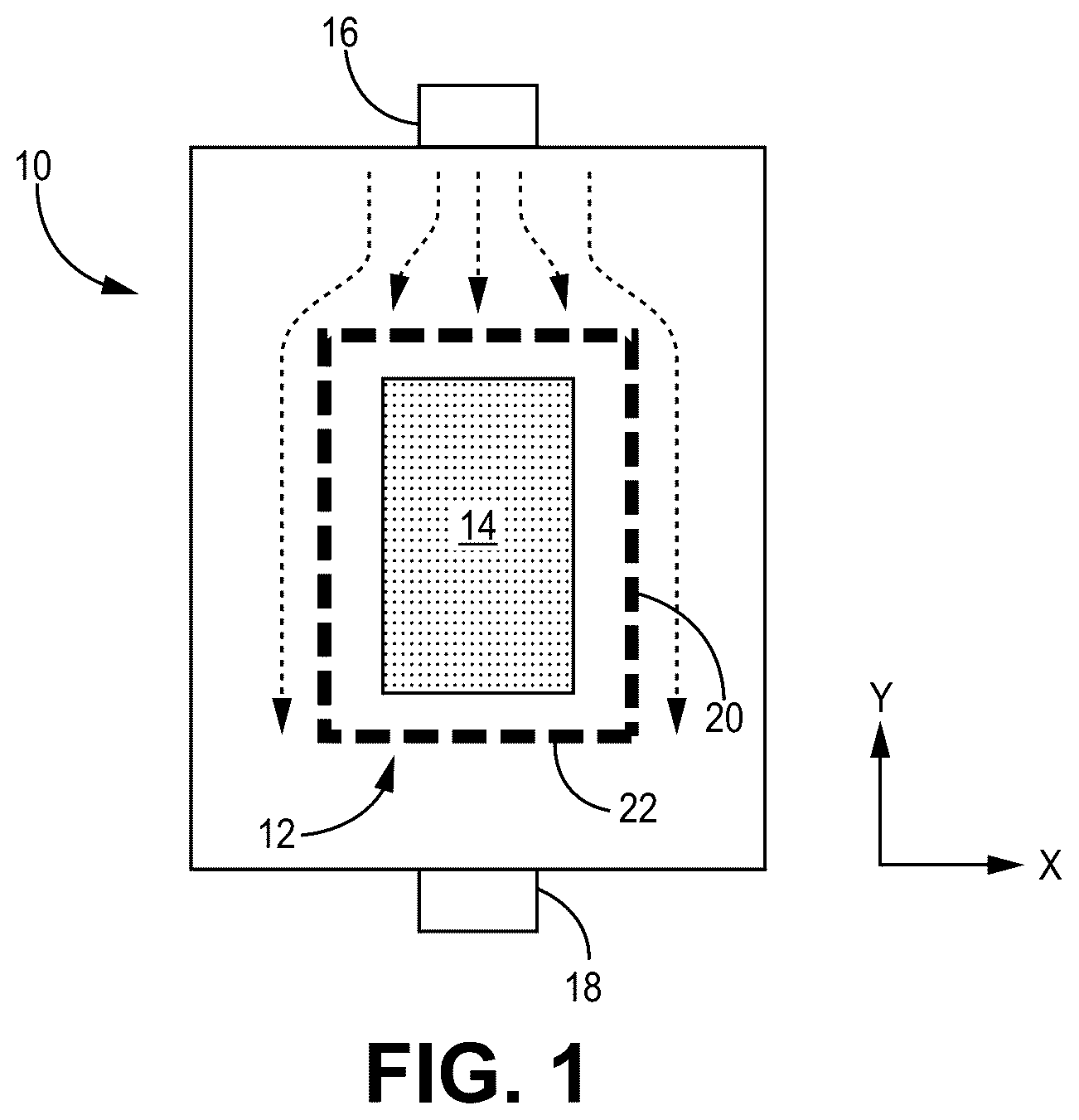
is a simplified illustration of a tooling fixture within a CVI reactor.
A is a simplified cross-sectional illustration of a tooling fixture with infiltration holes according to a first embodiment.
B is a simplified cross-sectional illustration of a tooling fixture with infiltration holes according to a second embodiment.
C is a simplified cross-sectional illustration of a tooling fixture with infiltration holes according to a third embodiment.
is a simplified illustration comparing the angles of the upstream corner of various infiltrations holes of A- 2 C .
While the above-identified figures set forth one or more embodiments of the present disclosure, other embodiments are also contemplated, as noted in the discussion. In all cases, this disclosure presents the invention by way of representation and not limitation. It should be understood that numerous other modifications and embodiments can be devised by those skilled in the art, which fall within the scope and spirit of the principles of the invention. The figures may not be drawn to scale, and applications and embodiments of the present invention may include features and components not specifically shown in the drawings.
DETAILED DESCRIPTION
This disclosure presents various inlet geometries for infiltration holes in a tooling fixture. More specifically, the inlets are widened and/or angled with respect to a flow of reactant gas based on the orientation of the tooling fixture within a CVI reactor. Such geometries minimize pressure losses and/or flow vortices to ensure sufficient flow volume through the holes.
is a simplified illustration of tooling fixture 10 positioned with CVI reactor 12 . Tooling fixture 10 is supporting preform 14 . Tooling fixture 12 can, in an exemplary embodiment, be formed from graphite. In an alternative embodiment, tooling fixture 12 can be all or partially formed from refractory metal alloys, carbon-carbon composites, and/or a ceramic (e.g., silicon carbide, aluminum oxide, boron nitride, etc.). Preform 14 can be formed from tows of silicon carbide (SiC) or other ceramic fibers arranged in one of various two or three-dimensional woven architectures such as plain, harness (e.g., 3, 5, 8, etc.), twill, braid, or non-symmetric to name a few non-limiting examples. In an alternative embodiment, preform 14 can be formed from non-woven (e.g., chopped, felted, etc.) fibers. Tooling fixture 12 can at least partially surround preform 14 to help maintain the shape of preform 14 during CVI. Tooling fixture 12 and preform 14 can each include straight and/or curved segments depending on the geometry desired in the final CMC part.
CVI reactor 12 includes inlet 16 and outlet 18 . A flow of reactant gas, represented by dashed arrows, can be introduced to CVI reactor 12 at inlet 16 and exhausted from CVI reactor 12 at outlet 18 . This flow of reactant gas therefore travels primarily along the y-axis (i.e., flow axis). Tooling fixture 12 includes multiple walls/sides 20 with infiltration holes 22 extending therethrough. The uppermost side 20 , proximate inlet 16 is disposed along the x-axis such that the flow of reactant gas is mostly normal to its surface, and parallel with its respective holes 22 . For sides 20 disposed along the y-axis, however, holes 22 are essentially disposed at a right angle with respect to the flow of reactant gas, as is shown in greater detail in A- 2 C .
For uniformly conical (i.e., straight-walled) holes, pressure loss and/or flow vortices at the hole's inlet caused by the turning of the flow into the inlet can at least partially block additional flow into the inlet, leading to insufficient flow of reactant gas through tooling fixture sides oriented in the flow direction. This can result in uneven IFC deposition on corresponding preform surfaces.
A, 2 B, and 2 C are simplified enlarged cross-sectional illustrations of alternative infiltration holes 22 A, 22 B, and 22 C, respectively, for a tooling fixture. A, 2 B , and 2 C are discussed together.
A illustrates a portion of side 20 A of tooling fixture 12 A, oriented along the y-axis. Tooling fixture 12 A includes inner (i.e., preform-facing) surface 24 A, oppositely disposed outer surface 26 A, and thickness TA extending therebetween. Thickness TA need not be uniform across the entirety of tooling fixture 12 A, although A depicts a section of uniform thickness. Each hole 22 A includes inlet 28 A at outer surface 26 A and outlet 30 A at inner surface 24 A. Reactant gas travels through tooling fixture 12 A in an inlet-to-outlet direction during CVI. Hole 22 A can include an inlet portion extending between inlet 28 A and transition point 32 A, and an outlet portion extending between transition point 32 A and outlet 30 A. Hole 22 A has a frustoconical three-dimensional geometry between inlet 28 A and transition point 32 A (i.e., inlet portion) forming a trapezoidal cross-sectional area (i.e., the plane visible in A ). Hole 22 A transitions to a cylindrical three-dimensional geometry at transition point 32 A, forming a rectangular cross-sectional area between transition point 32 A and outlet 30 A (i.e., outlet portion). Accordingly, hole 22 A has a first diameter D 1 at inlet 28 A which tapers linearly to transition point 32 A, and a uniform second diameter D 1 between transition point 32 A and outlet 30 A. D 1 is the largest diameter of hole 22 A, and D 1 >D 2 . In an exemplary embodiment, D 2 can be 0.125 in, and D 1 can be 0.131 in to 0.25 in. Corners 34 A are formed where inlet 28 A meets outer surface 26 A. The frustoconical geometry at inlet 28 A forms a reduced (i.e., <) 90° open angle ( ) at the upstream/upper corner 34 A with respect to the y-axis and the flow of reactant gas, which reduces pressure loss through hole 22 A. More specifically, the pressure drop coefficient K L for the frustoconical geometry can be lower than for a conical hole forming a right angle at outer surface 26 A.
B illustrates a portion wall 20 B of tooling fixture 12 B which is substantially similar to wall 20 A, having inner surface 24 B, outer surface 26 B and thickness TB extending therebetween. Hole 22 B can include an inlet portion extending between inlet 28 B and transition point 32 B, and an outlet portion extending between transition point 32 B and outlet 30 B. Wall 20 B differs from wall 20 B in that hole 22 B has a frustoconical bell mouth three-dimensional geometry (i.e., having an at least partially convexly curved segment) from inlet 28 B to transition point 32 B, and thereafter has a cylindrical three-dimensional geometry. Hole 22 B has a first diameter D 3 at inlet 28 B which curvilinearly tapers to transition point 32 B, and a uniform second diameter D 4 between transition point 32 B and outlet 30 B. D 3 is the largest diameter of hole 22 B, and D 3 >D 4 . In an exemplary embodiment, D 4 can be 0.125 in, and D 3 can be 0.131 in to 0.25 in. Corners 34 B are formed where inlet 28 B meets outer surface 26 B. Corners 34 B have non-right angles, with the upstream corner being greater than 90°. In addition to being non-right angles, corners 34 B are also curved which can help further minimize pressure losses compared to hole 22 A, in some cases achieving a lower K L value than hole 22 A under similar CVI conditions. In an alternative embodiment, hole 22 B can have more of a parabolic three-dimensional geometry with concave curvature between inlet 28 B and transition point 32 B.
C illustrates a portion of wall 20 C of tooling fixture 12 C which is substantially similar to walls 20 A and 20 B, having inner surface 24 C, outer surface 26 C and thickness Tc extending therebetween. Hole 22 C can include an inlet portion extending between inlet 28 C and transition point 32 C, and an outlet portion extending between transition point 32 C and outlet 30 C. Wall 20 C differs from walls 20 A and 20 B in that hole 22 C is directionally angled toward the flow of reactant gas, with a bell mouth shaped upstream corner 34 C and a pointed downstream corner 34 C. The geometry transitions to a cylinder, oriented along the x-axis at transition point 32 C. Hole 22 C has a first diameter D 5 at inlet 28 C which can be slightly larger, depending on the curvature, than the remaining diameter of the angled segment (i.e., upstream of transition point 32 C) which otherwise remains fairly uniform between inlet 28 C and transition point 32 C. Hole 22 C further includes second diameter D 6 , which is uniform between transition point 32 C and outlet 30 C. Depending on the embodiment, D 5 >D 6 , or D 5 =D 6 . D 6 can be 0.125 in. Corners 34 C are formed where inlet 28 C meets outer surface 26 C. Corners 34 C have non-right angles, with the upstream corner being greater than 90°. Angling inlet 28 C in the flow direction eliminates right angles, and further rounding upstream corner 34 C can reduce pressure losses in the same manner as the preceding examples.
is a simplified illustration of a portion of wall 120 showing upstream corner 134 , based on the direction of flow of reactant gases (represented as dashed arrows) along the y-axis. Corner 134 is formed where outer surface 126 of wall 120 meets inlet 128 . Line 136 represents the inner surface of a cylindrical hole, forming a 90° open angle at corner 134 . Line 138 represents the inner surface of a hole (i.e., hole 22 A) with a frustoconical geometry at the inlet portion, such that the inner surface forms an open angle at corner 134 that is less than 90°. Similarly, line 140 represents the inner surface of a hole (i.e., hole 22 B or 22 C) with a curved/bell mouth inner surface also forming open angle at corner 134 that is less than 90°.
Any of holes 22 A, 22 B, and/or 22 C can be included in a single wall and/or tooling fixture and/or combined with cylindrical holes depending on preform characteristics and/or placement of the tooling fixture within the CVI reactor. For example, holes 22 A, 22 B, and/or 22 C can be formed in walls expected to be parallel to the flow of reactant gas. They can also be formed in tooling fixture walls/locations aligned with a local preform thickness that is relatively thick, or in locations situated further from the reactant gas injection site/inlet where the concentration becomes more depleted. Holes 22 A, 22 B, and 22 C can be formed using a laser or mechanical drilling technique, including countersinking for frustoconical sections, and trepanning for curved and/or bell mouth inlets. The disclosed tooling fixtures can be used to form CMC components for aerospace, maritime, or industrial equipment, to name a few, non-limiting examples.
DISCUSSION OF POSSIBLE EMBODIMENTS
The following are non-exclusive descriptions of possible embodiments of the present invention.
A tooling fixture suitable for use in infiltrating a fibrous preform with a flow of reactant gas includes at least one wall. The at least one wall includes an outer surface and opposing inner surface defining a thickness therebetween, and a plurality of holes extending through the thickness. Each hole of the plurality of holes includes an inlet at the outer surface, an outlet at the inner surface, a transition point between the inlet and the outlet, and a first corner defined by the outer surface and the inlet. An angle of the first corner is greater than 90 degrees, each hole of the plurality of holes has a first diameter at the inlet and a second diameter at the outlet, and the second diameter is less than the first diameter.
The tooling fixture of the preceding paragraph can optionally include, additionally and/or alternatively, any one or more of the following features, configurations and/or additional components:
In the above tooling fixture, the first corner can be rounded.
In any of the above tooling fixtures, each hole of the plurality of holes can further include a frustoconical bell mouth geometry between the inlet and the transition point, and a cylindrical geometry between the transition point and the outlet.
In any of the above tooling fixtures, each hole of the plurality of holes can further include an angled geometry between the inlet and the transition point, and a cylindrical geometry between the transition point and the outlet.
In any of the above tooling fixtures, each hole of the plurality of holes can further include a frustoconical geometry between the inlet and the transition point, and a cylindrical geometry between the transition point and the outlet.
In any of the above tooling fixtures, the at least one wall can be disposed along a flow axis of the reactant gas.
In any of the above tooling fixtures, the tooling fixture can be formed from at least one of graphite, a refractory metal alloy, a carbon-carbon composite, and a ceramic material.
A tooling fixture suitable for use in infiltrating a fibrous preform with a flow of reactant gas includes at least one wall. The at least one wall includes an outer surface and opposing inner surface defining a thickness therebetween, and a plurality of holes extending through the thickness. Each hole of the plurality of holes includes an inlet at the outer surface, an outlet at the inner surface, a transition point between the inlet and the outlet, and a first corner defined by the outer surface and the inlet. An angle of the first corner is greater than 90 degrees.
The tooling fixture of the preceding paragraph can optionally include, additionally and/or alternatively, any one or more of the following features, configurations and/or additional components:
In the above tooling fixture, the first corner can be rounded.
Any of the above tooling fixtures can further include a second corner defined by the outer surface and the inlet.
In any of the above tooling fixtures, the second corner can be rounded.
In any of the above tooling fixtures, each hole of the plurality of holes can further include a frustoconical bell mouth geometry between the inlet and the transition point, and a cylindrical geometry between the transition point and the outlet.
In any of the above tooling fixtures, each hole of the plurality of holes can further include a first diameter at the inlet, and a uniform second diameter from the transition point to the outlet. The first diameter can be greater than the second diameter.
In any of the above tooling fixtures, each hole of the plurality of holes can further include an angled geometry between the inlet and the transition point, and a cylindrical geometry between the transition point and the outlet.
In any of the above tooling fixtures, each hole of the plurality of holes can further include a first diameter at the inlet, and a uniform second diameter from the transition point to the outlet. The first diameter can be greater than the second diameter.
In any of the above tooling fixtures, each hole of the plurality of holes can further include a frustoconical geometry between the inlet and the transition point, and a cylindrical geometry between the transition point and the outlet.
In any of the above tooling fixtures, each hole of the plurality of holes can further include a first diameter at the inlet, and a uniform second diameter from the transition point to the outlet. The first diameter can be greater than the second diameter.
In any of the above tooling fixtures, the at least one wall can be disposed along a flow axis of the reactant gas.
Any of the above tooling fixtures can further include a second wall disposed orthogonal or parallel to the at least one wall.
In any of the above tooling fixtures, the tooling fixture can be formed from at least one of graphite, a refractory metal alloy, a carbon-carbon composite, and a ceramic material.
While the invention has been described with reference to an exemplary embodiment(s), it will be understood by those skilled in the art that various changes may be made and equivalents may be substituted for elements thereof without departing from the scope of the invention. In addition, many modifications may be made to adapt a particular situation or material to the teachings of the invention without departing from the essential scope thereof. Therefore, it is intended that the invention not be limited to the particular embodiment(s) disclosed, but that the invention will include all embodiments falling within the scope of the appended claims.
Figures (5)
Citations
This patent cites (27)
- US3991248
- US4909914
- US5217755
- US8845806
- US10906205
- US10906842
- US11046620
- US11332827
- US2001/0050059
- US2007/0079934
- US2012/0097330
- US2012/0103264
- US2015/0214009
- US2017/0114462
- US2018/0340257
- US2020/0061868
- US2020/0123066
- US2020/0123067
- US2020/0308703
- US2022/0195606
- US2023/0047104
- US107266099
- US115181959
- US3805424
- USS58176196
- US5093165
- US7164632