Mold, Method of Producing Product, Method of Producing Image Forming Apparatus, and Non-transitory Computer-readable Recording Medium
Abstract
A mold includes a rotatable portion, a frame portion, a first and second portion, and a production unit. The rotatable portion has a plurality of surfaces and a plurality of forming portions. The plurality of surfaces is each provided with one of the plurality of forming portions, each having the same shape. The frame portion rotatably supports the rotatable portion. The first portion defines a cavity by coming into contact with one surface of the plurality of surfaces by clamping the mold. The second portion comes into contact with another surface of the plurality of surfaces different from the one surface by clamping the mold. The production unit attached to the frame portion.
Claims (23)
1 . A production apparatus comprising: a first mold including a first forming portion for forming a first member and a second forming portion for forming a second member, the first and second forming portions being arranged side by side, the first forming portion and/or the second forming portion being provided to be movable; a second mold; a drive portion configured to move the first mold or the second mold so that the first forming portion and the second forming portion of the first mold are in contact with the second mold; and a movement portion configured to rotate and/or move the first forming portion and/or the second forming portion to contact each other in a state in which the first forming portion holds the first member and the second forming portion holds the second member so that the first member and the second member are in contact with each other.
14 . A method of producing a product, the method comprising: preparing a first mold including a first forming portion for forming a first member and a second forming portion for forming a second member, the first and second forming portions being arranged side by side, the first forming portion and/or the second forming portion being provided to be movable; preparing a second mold used with the first mold; forming the first member by the first forming portion and the second member by the second forming portion; and rotating and/or moving the first forming portion and/or the second forming portion to contact each other in a state in which the first forming portion holds the first member and the second forming portion holds the second member so that the first member and the second member are in contact with each other.
Show 21 dependent claims
2 . The production apparatus according to claim 1 , wherein the movement portion is provided in the first mold.
3 . The production apparatus according to claim 1 , wherein the second mold has a surface provided with a third forming portion and a fourth forming portion, and wherein the first mold and the second mold are configured to be clamped together so that a first cavity is defined by the first forming portion and the third forming portion and a second cavity is defined by the second forming portion and the fourth forming portion.
4 . The production apparatus according to claim 3 , further comprising an injection unit configured to inject resin into at least one selected from the group consisting of the first cavity and the second cavity.
5 . The production apparatus according to claim 3 , wherein the first mold is configured to hold the first member formed in the first cavity and the second member formed in the second cavity.
6 . The production apparatus according to claim 5 , wherein the movement portion is configured to have the second member fit into or engage with the first member.
7 . The production apparatus according to claim 5 , further comprising an ejector pin for taking out a product formed by fitting or engaging the first member and the second member together.
8 . The production apparatus according to claim 1 , wherein at least one selected from the group consisting of the first forming portion and the second forming portion is configured to be detachable from the first mold.
9 . The production apparatus according to claim 1 , wherein the second mold includes a guide configured to fix the first mold.
10 . The production apparatus according to claim 1 , wherein the second mold has a surface provided with a third forming portion and a fourth forming portion.
11 . The production apparatus according to claim 1 , wherein the movement portion includes a plurality of gears and is configured to rotate and/or move at least one selected from the group consisting of the first forming portion and the second forming portion by moving the gears.
12 . The production apparatus according to claim 3 , wherein at least one selected from the group consisting of the first forming portion and the second forming portion is rotated and/or moved in a state where the first forming portion and the third forming portion do not define the first cavity.
13 . The production apparatus according to claim 1 , wherein the drive portion is configured to relatively move the second mold with respect to the first mold.
15 . The method according to claim 14 , wherein the first mold and the second mold are used in the forming; and wherein the rotating and/or moving makes the second member formed by the second forming portion face the first member formed by the first forming portion.
16 . The method according to claim 15 , wherein the first member and the second member are fitted or engaged together by the first forming portion and/or the second forming portion being moved.
17 . The method according to claim 16 , further comprising: releasing a product formed by fitting or engaging the first member and the second member together.
18 . The method according to claim 17 , wherein the product is a part of an image forming apparatus.
19 . A non-transitory computer-readable recording medium storing a control program for causing a control apparatus to execute the method according to claim 14 .
20 . The production apparatus according to claim 1 , wherein the movement portion is configured to move and separate the first forming portion holding the first member and/or the second forming portion holding the second member from the first mold so that the first forming portion holding the first member and the second forming portion holding the second member are in contact with each other.
21 . The production apparatus according to claim 1 , wherein the movement portion is configured to position a first surface opposite to the second mold on the first forming portion and a second surface opposite to the second mold on the second forming portion to face each other such that the first forming portion holding the first member and the second forming portion holding the second member are in contact with each other.
22 . The production apparatus according to claim 1 , wherein the movement portion is configured to contact the first forming portion holding the first member and the second forming portion holding the second member with each other and press the first forming portion holding the first member and the second forming portion holding the second member.
23 . The production apparatus according to claim 1 , wherein the first forming portion and the second forming portion are provided side by side on one mold surface of the first mold.
Full Description
Show full text →
CROSS-REFERENCE TO RELATED APPLICATIONS
This application is a continuation application of U.S. patent application Ser. No. 16/011,788, filed Jun. 19, 2018, which claims the benefit of Japanese Patent Application No. 2017-122598, filed Jun. 22, 2017, Japanese Patent Application No. 2017-122599, filed Jun. 22, 2017, and Japanese Patent Application No. 2018-101065, filed May 25, 2018. All of these prior applications are hereby incorporated by reference herein in their entirety.
BACKGROUND OF THE INVENTION
Field of the Invention
The present invention relates to a mold including a rotatable portion, a method of producing a product, a method of producing an image forming apparatus, and a non-transitory computer-readable recording medium.
Description of the Related Art
Conventionally, a unit part constituted by a plurality of resin members is assembled by an assembling robot or a manual work after individually forming the members constituting the unit part by an injection molding machine or the like and then conveying, in other words, supplying the members to a production line of the unit part.
In recent years, for example, as disclosed in Japanese Patent Laid-Open No. 2011-56774, an apparatus that forms a plurality of molded products using a rotatable intermediate mold, a first injection unit of an injection molding machine, and a second injection unit attached to the injection molding machine is proposed.
However, in such a molding machine as disclosed in Japanese Patent Laid-Open No. 2011-56774 described above, a large mechanism for moving the second injection unit is required, and thus there is a risk that the size of the apparatus increases. Further, since the second injection unit is attached to the injection molding machine, it is difficult to adjust the position of the second injection unit with respect to a mold.
SUMMARY OF THE INVENTION
According to one aspect of the present invention, a mold includes, a rotatable portion having a plurality of surfaces and a plurality of forming portions, the plurality of surfaces being each provided with one of the plurality of forming portions, the plurality of forming portions each having the same shape, a frame portion configured to rotatably support the rotatable portion a first portion configured to define a cavity by coming into contact with one surface of the plurality of surfaces by clamping the mold, a second portion configured to come into contact with another surface of the plurality of surfaces different from the one surface by clamping the mold, and a production unit attached to the frame portion.
According to another aspect of the present invention, a mold configured to define a cavity by bringing a first surface and a second surface into contact with each other. The mold has a movement portion configured to move a piece portion. A first forming portion and a second forming portion are formed on the first surface, and at least one of the first forming portion and the second forming portion is formed on the piece portion.
According to another aspect of the present invention, a method of producing a product by using a mold, the mold including: a rotatable portion having a plurality of surfaces and a plurality of forming portions, the plurality of surfaces being each provided with one of the plurality of forming portions, the plurality of forming portions each having the same shape, and a frame portion configured to rotatably support the rotatable portion. The method includes a step of forming a first formed member and a second formed member on a first surface of the rotatable portion by moving the first surface to a first position of the frame portion, and a step of moving the first formed member and the second formed member formed on the first surface to a second position of the frame portion by rotating the rotatable portion to subject part of at least one of the first formed member and the second formed member to a production process.
According to another aspect of the present invention, a method of producing a product uses a first formed member and a second formed member. The first formed member and the second formed member are formed at a second portion of a mold by injecting resin into a cavity defined by a forming portion formed in a first portion of the mold and a forming portion formed in the second portion of the mold and releasing solidified resin. The forming portion formed in the second portion includes a first forming portion and a second forming portion, the second forming portion being formed on a piece portion. The first formed member and the second formed member are joined with each other by moving the second formed member formed on the second forming portion onto the first formed member formed on the first forming portion by moving the piece portion.
Further features of the present invention will become apparent from the following description of exemplary embodiments (with reference to the attached drawings).
BRIEF DESCRIPTION OF THE DRAWINGS
is a perspective view of an example of a part produced in a first exemplary embodiment of the present invention.
A and 2 B illustrate a configuration of a mold, A being a perspective view of the mold, B being a top view of the mold illustrating a production process performed by the mold.
is a front view of a fixed portion illustrating a configuration thereof.
is a front view of a rotatable portion illustrating a configuration of a forming surface.
is an explanatory diagram illustrating an operation of closing the mold.
A to 6 C illustrate a state in which the mold is closed at a first process position, A being a side view of the mold, B being a longitudinal section view of the mold taken along an A-A line of A , C being a cross-section view of the mold taken along a B-B line of A.
A and 7 B illustrate a state in which a molded product is formed in the state of , A being a longitudinal section view of the mold of A taken along the A-A line, B being a cross-section view of the mold of B taken along the B-B line.
is a perspective view of the mold in an open state.
is a side view of the mold illustrating a state in which a formed member is held by a second forming portion.
is a perspective view of the mold illustrating a state in which the rotatable portion is rotated.
is a side view of the mold illustrating a state in which a second slide portion operates at a second process position.
A and 12 B respectively show a section view of the mold and illustrate a state in which resin is molded at the second process position of in detail.
is a side view of the mold illustrating a state in which the second slide portion is separated from the rotatable surface.
A is a side view of the mold illustrating an operation of a driving portion at a third process position, and B and 14 C are each an enlarged side view of a part of A .
A to 15 C respectively illustrate a top view of the driving portion illustrating how a mold piece is inverted and moved by the operation of A to 14 C .
A and 16 B respectively illustrate a section view of the mold illustrating a state in which resin is molded at the third process position.
is a perspective view of the mold illustrating a different configuration in which an injection unit is provided on a frame body.
A and 18 B respectively illustrate a perspective view of the mold illustrating a state at the time of releasing a formed member from a mold piece.
is a perspective view of the mold illustrating a state in which a produced part is taken out from the rotatable portion at a take-out position.
is a section view of the mold illustrating a state in which molding and assembly are performed by using four forming surfaces of the rotatable portion.
is a section view of the mold illustrating an arrangement of different forming surfaces of the rotatable portion and molding and assembly performed in this arrangement.
is a block diagram illustrating a configuration of a control system of the mold of the first exemplary embodiment of the present invention.
is a flowchart illustrating a control procedure of the mold by the control system of .
is a perspective view of an example of a part produced in a second exemplary embodiment of the present invention.
A and 25 B illustrate a configuration of a molding assembly apparatus according to the second exemplary embodiment, A being a perspective view of the molding assembly apparatus, B being a top view of the molding assembly apparatus illustrating a production process performed by the molding assembly apparatus.
is a front view of a mold according to the second exemplary embodiment illustrating a configuration thereof.
is a front view of a forming surface of the mold according to the second exemplary embodiment.
is a perspective view of the mold illustrating how the mold according to the second exemplary embodiment is closed.
A and 29 B illustrate a state in which the mold is closed at a first process position according to the second exemplary embodiment, A being a perspective view of the mold, B is a section view of the mold taken along an A-A line of A .
is a section view of the mold illustrating a state in which a resin member is formed in the state of A and 29 B .
is a perspective view of the mold according to the second exemplary embodiment illustrating a state in which the mold is opened.
is a front view of the mold according to the second exemplary embodiment illustrating a state in which the resin member is held by a forming portion of the mold.
A to 33 C are explanatory diagrams illustrating inversion and movement of a mold piece according to the second exemplary embodiment.
A and 34 B respectively illustrate a perspective view of the mold piece according to the second exemplary embodiment illustrating an operation of releasing the resin member from the mold piece.
is a side view of the molding assembly apparatus according to the second exemplary embodiment illustrating an operation of releasing the part from the molding assembly apparatus.
is an explanatory diagram illustrating a relationship between an injection molding machine and a mold.
DESCRIPTION OF THE EMBODIMENTS
First Exemplary Embodiment
A first exemplary embodiment of the present invention will be described below with reference to attached drawings. To be noted, configurations shown below are merely examples, and, for example, details thereof can be modified by one skilled in the art within the scope of the present invention. In addition, numerical values mentioned in the present exemplary embodiment are just for reference and should not limit the present invention.
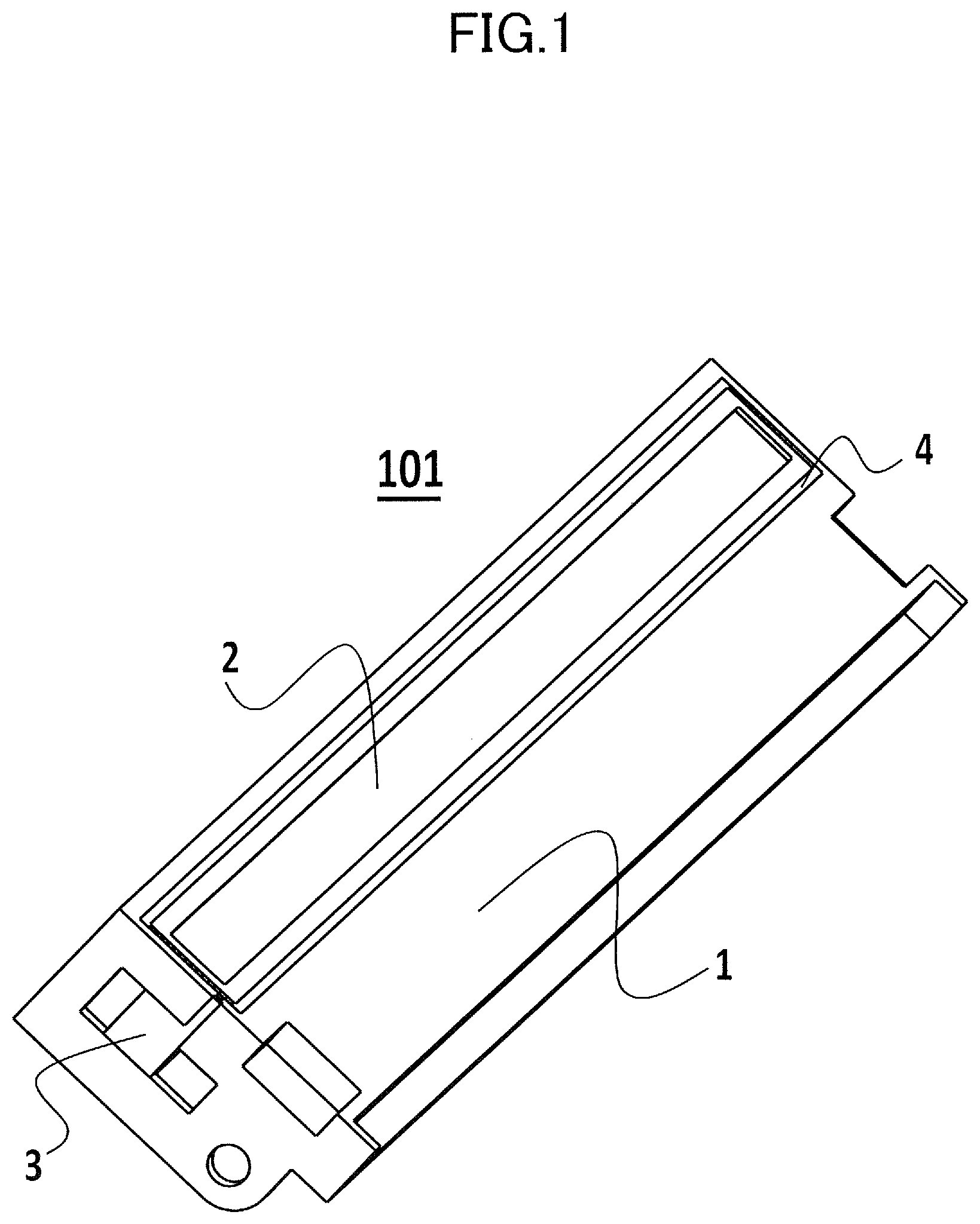
illustrates an example of a part 101 produced by a mold of the present exemplary embodiment. illustrates the part 101 that has been molded and assembled by using the mold of the present exemplary embodiment. The part 101 of is, for example, a part constituting an image forming apparatus, and includes formed members 1 , 2 , and 3 , and a joint member 4 .
The former members 1 to 3 and the joint member 4 are integrated as a unit as illustrated in by performing a production process by using a mold illustrated in, for example, A to 4 and 36 , and thereby serves as the part 101 of the image forming apparatus. The image forming apparatus has a mount configured to mount the part 101 , which can be produced as some cartridge part for the apparatus, by the production method of the present exemplary embodiment. The production process includes injection molding of a molding material, for example, molten resin, and assembly.
In the unitized state of , the formed member 3 is integrally formed with the formed member 1 . In addition, the formed member 1 and the formed member 2 are positioned each other by engaging with each other, and are joined with each other by the joint member 4 .
A to 4 , 20 , and 36 illustrate a configuration of a mold serving as the mold of the present exemplary embodiment. A is a perspective view of the mold, and B is a top view of the mold. is a front view of a fixed portion 5 viewed in an X10 direction of B . is a front view of a first forming surface 30 a of a rotatable portion 6 viewed in an X11 direction of B . is a diagram illustrating a relationship between an injection molding machine and a mold.
As illustrated in A to 4 , 20 , and 36 , a mold 900 of the present exemplary embodiment includes a first portion 5 , a second portion 7 , and a third portion 60 . The first portion 5 is also sometimes referred to as a fixed portion 5 , and the second portion 7 is also sometimes referred to as a movable portion 7 . The third portion 60 includes the rotatable portion 6 and a frame portion 11 , and the rotatable portion 6 is rotatably supported by the frame portion 11 . In the present description, a portion other than the rotatable portion 6 in the third portion 60 is referred to as the frame portion 11 .
Further, the rotatable portion 6 includes a plurality of forming surfaces including a first forming surface 30 a , a second forming surface 30 b , a third forming surface 30 c , and a fourth forming surface 30 d . These forming surfaces are each provided with a forming portion formed thereon. The forming portion is capable of forming a molded product of the same shape. In addition, the forming portion may be formed such that a part thereof is movable. Details of this will be described later. That is, the forming surface may be formed by embedding a plurality of members serving as piece portions on each of which the forming portion is formed, and at least one of the plurality of piece portions may be movably configured. In addition, the frame portion 11 of the mold of the present exemplary embodiment includes production units, for example, production units 7 a , 7 b , 9 a , and 10 a , for performing a production process of molding and/or assembly. The respective forming portions formed on the respective forming surfaces described above are positioned at respective production process positions in the order of the production process by pivoting the rotatable portion 6 about a pivot center. Further, production of a plurality of the same parts is progressed in parallel by performing different production steps of molding and/or assembly by respectively using the first portion 5 , the second portion 7 , and the production units at the respective process positions. As a result of this, an excellent effect of producing a part requiring a plurality of times of injection molding and an assembly step by a configuration of a small size and weight and low cost can be achieved.
That is, as illustrated in A and 2 B , the mold of the present exemplary embodiment includes the first portion 5 serving as a fixed portion, the third portion 60 including the frame portion 11 and the rotatable portion 6 supported by the frame portion 11 , and the second portion 7 serving as a movable portion. The fixed portion 5 is fixed to a fixed board 901 of an injection molding machine as illustrated in , and the rotatable portion 6 and the movable portion 7 can be moved in an X direction of opening or clamping the mold with respect to the fixed portion 5 . That is, the first portion 5 defines a cavity by coming into contact with one of the plurality of surfaces of the rotatable portion 6 by clamping the mold. Further, as a result of clamping the mold, the second portion 7 comes into contact with a surface different from the surface that comes into contact with the first portion 5 among the plurality of surfaces. In the present exemplary embodiment, production of a plurality of the same parts can be progressed in parallel by attaching the mold 900 of the present exemplary embodiment to an injection molding machine generally used for forming a molded product. Specifically, the fixed portion 5 is attached to the fixed board 901 and the movable portion 7 is attached to a movable board 902 of the generally used injection molding machine. An attachment portion 901 of the fixed portion 5 is connected to an injection mechanism 903 for molten resin of the injection molding machine. The molten resin injected by the injection mechanism 903 reaches to an inlet 903 a of the fixed portion 5 shown in A , through the attachment portion 901 .
The frame portion 11 is, for example, a frame body including four strut portions as illustrated, and the rotatable portion 6 is supported to be rotatable with respect to the frame portion 11 about a pivot shaft 90 serving as a pivot center. The rotatable portion 6 can be pivoted about the pivot shaft 90 in, for example, an R direction, by a driving portion, and thus can be positioned at a specific pivot position. For example, the driving portion 12 is disposed below the frame portion 11 and includes an electric motor and a transmission mechanism.
The rotatable portion 6 includes at least two forming surfaces that can be positioned so as to face four opening portions between the four struts of the frame portion 11 by being pivoted by the driving portion 12 . In the present exemplary embodiment, the rotatable portion 6 overall has a quadrangular prism shape and includes four forming surfaces each having the same forming portion. The rotatable portion 6 of the mold 900 of the present exemplary embodiment is pivotally supported by the frame portion 11 via the pivot shaft 90 , and thus can be positioned with a high precision with respect to, for example, the fixed portion 5 and the movable portion 7 that relatively move with respect to the frame portion 11 .
As illustrated in A and 36 , the mold of the present exemplary embodiment includes a plurality of guides 501 extending in the left-right direction in the figures. In this example, four guides 501 are provided. The guides 501 are fixed with respect to the first portion 5 serving as a fixed portion. In the present exemplary embodiment, the guides 501 penetrate the frame portion 11 of the third portion 60 and the second portion 7 serving as a movable portion as illustrated. The mold can be clamped and opened by controlling the positions of the frame portion 11 of the third portion 60 and the second portion 7 serving as a movable portion on the guides 501 by a driving system 904 provided in the injection molding machine. That is, the mold can be clamped and opened by relatively moving the rotatable portion 6 supported by the frame portion 11 of the third portion 60 and the first portion 5 serving as a fixed portion or relatively moving the rotatable portion 6 supported by the frame portion 11 of the third portion 60 and the second portion 7 serving as a movable portion.
To be noted, in the present exemplary embodiment, the first portion 5 serving as a fixed portion is fixed to a fixed board of the injection molding machine. However, this is for the sake of convenience, and any configuration can be employed as long as the third portion 60 and the first portion 5 serving as a fixed portion or the third portion 60 and the second portion 7 serving as a movable portion are relatively movable from each other. In addition, a configuration in which one of the first portion 5 serving as a fixed portion, the second portion 7 serving as a movable portion, and the frame portion 11 is fixed to a fixed board of the injection molding machine may be employed. In addition, a configuration in which both of the first portion 5 serving as a fixed portion and the second portion 7 serving as a movable portion move may be employed.
In the mold of the present exemplary embodiment, as illustrated in B , a first production process position 150 a , a second production process position 150 b , a third production process position 150 c , and a take-out position 150 d are set for the frame portion 11 . The first production process position 150 a corresponds to a position of a production process performed by the fixed portion 5 and first slide portions 7 a and 7 b . The second production process position 150 b corresponds to a production process performed by an injection unit 9 a . The third production process position 150 c corresponds to a position of a production process performed by the movable portion 7 , a driving portion 10 a , and an injection unit 9 b . In the present description, the first production process position is sometimes simply referred to as a first process position, the second production process position is sometimes simply referred to as a second process position, and the third production process position is sometimes simply referred to as a third process position.
In the present exemplary embodiment, the rotatable portion 6 has a prismatic shape and includes a forming portion of the same shape on each of four different surfaces thereof to be used for forming the same part 101 illustrated in . Therefore, by pivoting the rotatable portion 6 by the driving portion 12 , the forming portions of the four surfaces of the rotatable portion 6 can be sequentially moved to the first process position 150 a , the second process position 150 b , the third process position 150 c , and the take-out position 150 d . As a result of this, a different production process of molding and/or assembly can be performed by the fixed portion 5 , the movable portion 7 , or the production units at each process position, and thus production of a plurality of the same parts can be progressed in parallel.
The frame portion 11 of the present exemplary embodiment is provided with the first slide portions 7 a and 7 b illustrated in A that moves in synchronization with the relative movement of the frame portion 11 and the fixed portion 5 . The first slide portions 7 a and 7 b each include an angular pin capable of moving the first slide portion 7 a or 7 b by using a relative displacement between the frame portion 11 and the fixed portion 5 at the first process position 150 a . Therefore, the apparatus does not require a drive source such as a motor, a solenoid, or an air cylinder, and thus can be configured at relatively low cost.
In addition, the injection unit 9 a illustrated in B and the injection unit 9 b illustrated in A for injection molding of the part 101 are respectively disposed on the frame portion 11 and the movable portion 7 . These injection units 9 a and 9 b are respectively used at the second process position 150 b and the third process position 150 c . According to such a configuration, the size and weight of the entirety of a production apparatus can be reduced as compared with a conventional configuration disclosed in, for example, Japanese Patent Laid-Open No. 2011-56774. In the present exemplary embodiment, as illustrated in B , a direction in which the fixed portion 5 and the movable portion 7 are opened and closed is set as a direction of an X axis, and a direction perpendicular to this direction of the X axis is set as a direction of a Y axis.
In addition, as will be described later, at the third process position 150 c , driving portions 10 a and 10 b illustrated in A to 15 C that invert and move a formed member 2 and a piece portion 32 a thereof on forming surfaces 30 a to 30 d are disposed in the frame portion 11 . These driving portions 10 a and 10 b are respectively driven by movement portions 110 b and 110 c each including, for example, an air cylinder and an angular pin. The configurations and operations of the driving portions 10 a and 10 b will be described later in detail.
The fixed portion 5 includes forming portions 21 and 22 for respectively forming formed members 1 and 2 illustrated in constituting the part 101 as illustrated in .
The rotatable portion 6 of the present exemplary embodiment has an approximately quadrangular prism shape and has four forming surfaces therearound. illustrates the forming surface 30 a , which is one of the forming surfaces of the rotatable portion 6 , as viewed from the right in A and 2 B . The forming surface 30 a and the other three forming surfaces 30 b to 30 d of the rotatable portion illustrated in, for example, , all have the same configuration, and constitute forming portions of the same shape used for molding the same parts. That is, the rotatable portion 6 of the present exemplary embodiment is constituted by disposing a forming portion of the same shape used for molding the same part on each of a plurality of different surfaces disposed around a pivot center. Although the configuration of the forming surface 30 a of the rotatable portion 6 will be mainly described below, the same applies to the configurations of the other forming surfaces 30 b to 30 d.
In the present exemplary embodiment, an example in which the mold takes four positions including process positions and a take-out position is shown, and thus forming portions of the same shape are formed on all of the four surfaces of the rotatable portion 6 . However, the configuration is not limited to this. For example, in the case where only three positions including process positions and a take-out position are set, forming portions of the same shape may be formed on three surfaces. In addition, in the case where only two positions including a process position and a take-out position are set, forming portions of the same shape may be formed on two surfaces.
Piece portions 31 a and 32 a for respectively forming the formed members 1 and 2 illustrated in constituting the part 101 are provided on the forming surface 30 a of the rotatable portion 6 as first and second forming portions.
Here, for example, the forming surface 30 a , which is one of the forming surfaces of the rotatable portion 6 , is moved to the first process position 150 a by pivoting the rotatable portion 6 . At this time, the piece portions 31 a and 32 a are positioned so as to respectively oppose the forming portions 21 and 22 of the fixed portion 5 . Further, in the case where the rotatable portion 6 is pivoted in the R direction by 90°, the second forming surface 30 b illustrated in A is moved to a forming position opposing the first forming portions 21 and 22 of the fixed portion 5 as illustrated in . In addition, as a result of the 90° rotation of the rotatable portion 6 , the forming surface 30 a advances to the second process position 150 b.
As shown below, similarly, by rotating the rotatable portion 6 by 90° each time, the forming surfaces 30 a to 30 d can be sequentially moved to the first process position 150 a , the second process position 150 b , the third process position 150 c , and the take-out position 150 d.
Next, a production procedure of the part 101 of the present exemplary embodiment will be described. In addition, a more detailed configuration of the mold will be also described below. In the present exemplary embodiment, the formed members 1 , 2 , and 3 and the joint member 4 constituting the part 101 of are formed through first to sixth steps. Among the first to sixth steps, some adjacent steps are performed at the same process position.
The first step is shown in to 7 . In the first step indicated by K1 in B , first, as illustrated in , the rotatable portion 6 is pivoted about the pivot shaft 90 of the rotatable portion 6 such that the first forming surface 30 a is positioned at the first process position 150 a defined by the fixed portion 5 . Then, the fixed portion 5 and the rotatable portion 6 are closed by relatively moving the fixed portion 5 and the rotatable portion 6 . To be noted, in , a direction in which the rotatable portion 6 approaches the fixed portion 5 is indicated by an arrow X1.
As illustrated in , 5 , and 6 B , inclined angular pins 70 a and 70 b are implanted inside the fixed portion 5 . These angular pins 70 a and 70 b penetrate through the first slide portions 7 a and 7 b . The first slide portions 7 a and 7 b are supported so as to be slidable in the vertical direction in B with respect to the frame portion 11 . Therefore, in the case where the rotatable portion 6 relatively moves in the X1 direction with respect to the fixed portion 5 for clamping the mold, the first slide portions 7 a and 7 b respectively linearly move downward and upward.
B and 6 C illustrate a state in which the fixed portion 5 is clamped. In this clamped state, the first slide portions 7 a and 7 b move along the angular pins 70 a and 70 b and seal the top and bottom of the cavity 80 a defined by the forming portion 21 of the fixed portion 5 and the piece portion 31 a of the rotatable portion 6 . That is, as a result of the movement, the first slide portions 7 a and 7 b come into contact with at least one of the fixed portion 5 and the rotatable portion 6 . As a result of this, the cavity 80 a is defined. According to such a configuration, injection molding can be performed even for a molded product having a relatively complex structure on end portions thereof such as the formed member 1 of the part 101 illustrated in .
Subsequently, as illustrated in B and 6 C , a plurality of cavities 80 a and 80 b are defined by the first forming portions 21 and 22 of the fixed portion 5 , the piece portions 31 a and 32 a of the rotatable portion 6 , and the first slide portions 7 a and 7 b . Then, molten resin is injected from the injection molding machine into the cavities 80 a and 80 b that in the molds. According to this, the formed members 1 and 2 are formed by injection molding as illustrated in A and 7 B . To be noted, the format of illustration of A and 7 B is the same as B and 6 C . The injection of molten resin in the first step is performed by, for example, an unillustrated injection molding machine attached to the fixed portion 5 . In addition, illustration of flow paths of the resin such as a runner and a gate in the fixed portion 5 is omitted in the present exemplary embodiment, and the configuration of the flow paths of the resin does not constitute the present invention and can be arbitrarily modified by one skilled in the art.
Next, the second step will be described with reference to A, 2 B, 8 , and 9 . illustrates a state in which the fixed portion 5 and the frame portion 11 supporting the rotatable portion 6 are opened. illustrates a state in which the formed members 1 and 2 that have been formed are held by the piece portions 31 a and 32 a.
In this second step indicated by K2 in B , as illustrated in , the mold is opened by moving the movable portion 7 and the frame portion 11 supporting the rotatable portion 6 in an X2 direction away from the fixed portion 5 . At this time, the first slide portions 7 a and 7 b move in a direction to move away from the piece portion 31 a of the rotatable portion 6 along the angular pins 70 a and 70 b contrary to the case of clamping the mold. In addition, by opening the fixed portion 5 and the frame portion 11 supporting the rotatable portion 6 , the formed members 1 and 2 that have been formed are released from the first forming portions 21 and 22 of the fixed portion 5 , and are respectively held by the piece portions 31 a and 32 a of the rotatable portion 6 as illustrated in .
Next, the third step will be described with reference to A, 2 B, 10 , 11 , 12 A, and 12 B . illustrates a state in which the rotatable portion 6 is being pivoted so as to move the forming surface 30 a to the second process position 150 b and move the forming surface 30 b to the first process position 150 a.
illustrates a state after the pivoting described above has been completed, that is, a state in which the operation of moving the forming surface 30 b of the rotatable portion 6 to the first process position 150 a and moving the forming surface 30 a to the second process position 150 b has been completed. This corresponds to, for example, a side view of the rotatable portion 6 , a second slide portion 8 , and the injection unit 9 a as viewed from the right in .
As illustrated in , at the second process position 150 b , the second slide portion 8 and the injection unit 9 a attached thereto are relatively moved in a Y1 direction with respect to the forming surface 30 a of the rotatable portion 6 by a movement portion 110 a . This movement portion 110 a can be constituted by, for example, an air cylinder.
A illustrates a longitudinal section view of the mold in a state in which the second slide portion 8 is clamped afterwards with respect to the piece portion 31 a and the formed member 1 held by the piece portion 31 a constituting the forming surface 30 a of the rotatable portion 6 . In addition, B corresponds to a section view of the mold at the time of performing injection molding by injecting molten resin by the injection unit 9 a into a cavity defined by the forming surface 30 a of the rotatable portion 6 and the second slide portion 8 at the second process position 150 b.
In the third step indicated by K2 in B , as illustrated in , the rotatable portion 6 is rotated in the R direction by 90° about the pivot shaft 90 with respect to the driving portion 12 , and thus the first forming surface 30 a is moved to the second process position 150 b . According to this, the second forming surface 30 b moves to the first process position 150 a.
Next, as illustrated in , the second slide portion 8 disposed in the frame portion 11 and the injection unit 9 a are moved in the Y1 direction toward the rotatable portion 6 by the movement portion 110 a . As a result of this, the second slide portion 8 is clamped with respect to the formed member 1 held by the piece portion 31 a as illustrated in A . To be noted, the second slide portion 8 may be configured to come into contact with only the piece portion 31 a or both the formed member 1 and the piece portion 31 a , or also with the rotatable portion 6 . Such details of the configuration may be appropriately modified in accordance with the shape of the formed member 3 formed in this step.
Next, as illustrated in A and 12 B , molten resin is injected by the injection unit 9 a into a cavity 80 C defined by the second slide portion 8 and the formed member 1 , and thus the formed member 3 is formed on the formed member 1 . To be noted, illustration of the configuration of flow paths of resin such as a runner is also omitted herein. As described above, in the present exemplary embodiment, the formed member 3 is directly formed, by the second slide portion 8 and the injection unit 9 a provided to the frame portion 11 supporting the rotatable portion 6 , integrally with the formed member 1 held by the rotatable portion 6 . With such a configuration, the formed member 3 can be formed with a high precision.
Next, the fourth step will be described with reference to A, 2 B, 5 , 10 , and 13 to 17 . illustrates a state in which the second slide portion 8 is separated from the rotatable portion 6 . A to 14 C illustrate an operation of the driving portion 10 a . A to 15 C illustrate a state in which the piece portion 32 a is inverted and moved by the driving portion 10 a . In addition, illustrates how the joint member 4 is formed. Further, illustrates a modification example in which the frame portion 11 a is provided with an injection unit 9 c.
In the fourth step indicated by K3 in B , as illustrated in , the second slide portion 8 is moved in a direction Y2, away from the rotatable portion 6 . Then, in a state in which the formed member 1 on which the formed member 3 has been formed and the formed member 2 are respectively held by the rotatable portion 6 , and the rotatable portion 6 is rotated in the R direction by 90° about the pivot shaft 90 as illustrated in and is thus moved to the third process position 150 c illustrated in B .
A to 14 C illustrate the rotatable portion 6 , the second slide portion 8 , and the injection unit 9 a as viewed in a direction opposite to , for example, from the left in .
As illustrated in A , at the third process position 150 c illustrated in B , driving portions 10 a and 10 b are respectively disposed at top and bottom end portions of the frame portion 11 . The driving portions 10 a and 10 b have equivalent configurations although the orientations of main components thereof are vertically inverted.
In the present exemplary embodiment, movement portions 110 b and 110 c are each constituted by an air cylinder and an angular pin. By using these movement portions 110 b and 110 c , the driving portions 10 a and 10 b supported by the frame portion 11 can be respectively moved downward and upward. That is, by moving the movement portions 110 b and 110 c in the Y2 direction, the driving portions 10 a and 10 b can be moved closer to end surfaces 39 a and 39 b of the piece portion 32 a by which the formed member 2 is held and thus can be brought into contact with the piece portion 32 a as illustrated in B and 14 C .
Meanwhile, the piece portion 32 a holding the formed member 2 is provided with shafts 40 a and 40 b at the end surface 39 a that comes into contact with the driving portion 10 a as illustrated in A to 14 C and 15 A to 15 C . In addition, the end surface 39 b that comes into contact with the driving portion 10 b is provided with shafts 40 c and 40 d as illustrated in A . According to such a configuration, the piece portion 32 a can be inverted and moved by the driving portions 10 a and 10 b , and thus the formed member 2 can be engaged with the formed member 1 supported by the piece portion 31 a.
That is, when the driving portions 10 a and 10 b are respectively moved downward and upward by the movement portions 110 b and 110 c , the shafts 40 a and 40 b that are implanted in top and bottom end surfaces of the piece portion 32 a engage with a groove 50 a of a guide portion included in the driving portion 10 a as illustrated in A . As illustrated in A to 15 C , the U-shaped groove 50 a constituting the guide portion is defined in a flat plate portion of the driving portion 10 a . In addition, gears 120 a and 121 a that engage with each other are provided within the U-shape of the groove 50 a , and, for example, the gear 120 a is driven by a rotation driving portion such as an electric motor whose details are not illustrated. In addition, a lever 51 a is fixed to a pivot shaft of the gear 121 a as illustrated in B and 14 C .
As illustrated in A to 15 C , in the case where the gear 120 a is rotated in an arrow Ra direction in a state in which the shafts 40 a and 40 b are engaged with the groove 50 a of the guide portion, the gear 121 a rotates in an arrow Rb direction. Then, in accordance with the rotation of the gear 121 a , the lever 51 a is rotationally displaced as illustrated in A to 15 C , and moves the shaft 40 a of the piece portion 32 a along the U-shaped groove 50 a.
That is, the lever 51 a comes into contact with the shaft 40 a and moves the shafts 40 a and 40 b along the groove 50 a of the guide portion. The piece portion 32 a is configured to be separable from the rotatable portion 6 , and can be inverted, that is, flipped over by 180°, and moved toward the formed member 1 as illustrated in B and 15 C .
As described above, by inverting and moving the formed member 2 with the piece portion 32 a , the formed member 2 can be assembled with, in other words, mounted on the formed member 1 . To be noted, appropriate engagement portions such as engagement claws and grooves may be provided between the formed members 1 and 2 whose details are not illustrated, and the mutual positioning of the formed member 1 and 2 may be performed by pushing the formed member 2 by the driving portions 10 a and 10 b.
Then, the movable portion 7 is moved in the X1 direction illustrated in , that is, toward the rotatable portion 6 and the frame portion 11 , and thus the movable portion 7 and the rotatable portion 6 are closed. Then, molten resin is injected by the injection unit 9 b to form the joint member 4 of , and thus the formed member 2 and 1 are joined.
That is, in the case where the piece portion 32 a is inverted and the formed member 2 is mounted on the formed member 1 as illustrated in A to 15 C , the section is as illustrated in A . In the case where the movable portion 7 and the rotatable portion 6 are closed at this time, the movable portion 7 presses the piece portion 32 a , and thus opposing surfaces 1 a and 2 a of the formed members 1 and 2 are brought into firm contact as illustrated in A .
In the state of A , a cavity 80 d for forming the joint member 4 illustrated in is defined in a portion around the formed member 2 between the formed members 1 and 2 . Therefore, by injecting molten resin from the injection unit 9 b provided at the movable portion 7 into the cavity 80 d defined by the formed members 1 and 2 and the piece portion 32 a as illustrated in B , the joint member 4 is formed, and thus the formed members 1 and 2 are joined.
To be noted, in the present exemplary embodiment, the injection unit 9 b for injection molding of the joint member 4 is disposed on the movable portion 7 as illustrated in . However, the injection of resin into the mold may be performed from the side of the piece portion 32 a of the rotatable portion 6 instead of the side of the movable portion 7 . In this case, as illustrated in , for example, a configuration in which an injection unit 9 c is disposed on a frame portion 11 a and an unillustrated flow path for resin is appropriately joined between the injection unit 9 c and the piece portion 32 a at the third process position 150 c may be employed. However, injection molding of the joint member 4 is not always necessary. For example, depending on the specification of the part 101 , a configuration in which the formed members 1 and 2 are assembled into a single assembly by connecting engagement portions or fitting portions disposed on the formed member 1 and 2 by inverting and moving the piece portion 32 a as illustrated in A to 15 C may be employed.
As described above, in the present exemplary embodiment, a plurality of forming portions, which are the piece portions 31 a and 32 a in the present exemplary embodiment, respectively for the formed members 1 and 2 are disposed on each of the forming surfaces 30 a to 30 d of the rotatable portion 6 . Further, by inverting and moving the piece portion 32 a toward the piece portion 31 a at the third process position 150 c as illustrated in A to 15 C , the formed members 1 and 2 are combined and assembled, or further joined by resin. As described above, in the present exemplary embodiment, since the formed members 1 and 2 whose combination is limited is combined on the same forming surface of the rotatable portion 6 , the part 101 can be produced with a high precision.
Next, the fifth step will be described with reference to A, 2 B, 8 , 14 , 15 , and 18 . illustrates how the formed member 2 is released from the piece portion 32 a of the rotatable portion 6 .
In the fifth step indicated by K3 in B , the mold is opened by moving the movable portion 7 in an X2 direction away from the rotatable portion 6 illustrated in . As illustrated in A and 18 B , the driving portion 10 a is operated in an order reversed from the order illustrated in A to 15 C as illustrated in A to 18 B , and the state is returned to the state of A . The same applies to the case of the driving portion 10 b . At this time, the formed member 2 is released from the piece portion 32 a.
For example, as illustrated in A and 18 B , the gear 120 a of the driving portion 10 a is rotated in an Rc direction. As a result of this, the lever 51 a and the gear 121 a rotate in an Rd direction, the lever 51 a comes into contact with the shaft 40 b , and causes the piece portion 32 a to invert and move in a direction opposite to along the groove 50 a . As a result of this, the piece portion 32 a is inverted and moved in a direction away from the formed member 1 . In addition, although what has been described above is an operation related to the driving portion 10 a , a similar operation is performed on the driving portion 10 b side.
At this time, the formed member 2 has been already joined to the formed member 1 by the joint member 4 , and the joining force thereof is stronger than the holding force between the piece portion 32 a and the formed member 2 . Therefore, the formed member 2 is released from the piece portion 32 a and remains on the formed member 1 . Then, the driving portions 10 a and 10 b are operated in the order reversed from B and 14 C to respectively move upward and downward, and thus are separated from the piece portion 32 a.
Next, the sixth step of taking out the part 101 that has been molded and assembled will be described with reference to , 10 , 19 , and 20 . illustrates how the formed members 1 , 2 , and 3 are released from the rotatable portion 6 . In addition, illustrates a section view of the mold illustrating a state in which molding, assembly, or taking out is performed on all of the forming surfaces 30 a to 30 d of the rotatable portion 6 .
In the sixth step indicated by K4 of B , the rotatable portion 6 is pivoted in the R direction by 90° about the pivot shaft 90 by a driving portion 12 in a state in which the formed members 1 to 4 have been molded and assembled on a forming surface of the rotatable portion 6 , for example, the forming surface 30 a , as illustrated in . As a result of this, the forming surface 30 a is moved to the take-out position 150 d as illustrated in . At this take-out position 150 d , the formed members 1 to 3 are included in the rotatable portion 6 , pushed out and released by, for example, ejector pins 100 driven by a solenoid or an air cylinder, and thus taken out. The drive source of the ejector pins 100 used at this time, for example, the solenoid or air cylinder may be provided on the frame portion 11 side instead of in the rotatable portion 6 . In the manner described above, the formed members 1 to 3 are molded and assembled, and thus the part 101 illustrated in is completed.
In the present exemplary embodiment, as illustrated in , the part 101 completed by the formed members 1 to 3 is taken out at the take-out position 150 d in a state in which the rotatable portion 6 and the frame portion 11 and the movable portion 7 and the fixed portion 5 are closed. According to this, at the first process position 150 a , formed members 1 d and 2 d can be formed on the forming surface 30 d . In addition, at the second process position 150 b , a formed member 3 c can be formed on a formed member 1 c on the forming surface 30 c by the slide portion 8 and the injection unit 9 a . Further, at the third process position 150 c , a formed member 2 b can be joined with a formed member 1 b on the forming surface 30 b by inversion and movement of the piece portion 32 a and injection molding of the joint member 4 . In addition, at the take-out position 150 d , the part 101 constituted by the formed members 1 to 3 that have been molded and assembled is released by ejector pins 108 corresponding to the ejector pins 100 of and is thus taken out.
As described above, in the present exemplary embodiment, the steps described above can be sequentially performed in parallel on the four different forming surfaces 30 a to 30 d of the rotatable portion 6 having the same configuration, and thus molding and assembly can be successively performed with a high precision. As a result of this, a large number of parts 101 can be successively produced with a remarkably high efficiency.
To be noted, although a configuration in which the four different forming surfaces 30 a to 30 d having the same configuration are disposed on the rotatable portion 6 has been described above, the number of forming surfaces disposed on the rotatable portion 6 may be arbitrarily selected depending on the number of steps for production of the part. For example, illustrates an exemplary configuration in which two different forming surfaces having the same configuration are disposed as opposing surfaces of the rotatable portion 6 and molding and assembly are performed at the first process position 151 a and the second process position 151 b . Alternatively, a configuration in which molding and assembly are performed by using three surfaces of the rotatable portion 6 similarly having a quadrangular prism shape may be employed. In addition, although there is a possibility that the mechanism for opening and closing the mold becomes more complex, a configuration in which the rotatable portion 6 has the same forming surface on each of n side surfaces, for example, having an n-angular prism shape, may be employed. According to such a configuration, the production process can be progressed sequentially and in parallel by using the n forming surfaces having the same shape, and thus the production efficiency of the mold can be remarkably improved.
Here, a configuration of a control system of the mold of the present exemplary embodiment and an example of a control procedure of production of the part will be described with reference to .
A control apparatus of controls the molding and assembly described above by controlling a driving apparatus 611 serving as a driving system of the mold described above and an injection molding apparatus 612 serving as an injection system that is involved in injection of molten resin and maintaining or reducing the temperature of the mold. The driving apparatus 611 serving as a driving system includes the driving portion 12 that pivots the rotatable portion 6 , the electric motor that drives the gear 120 a of the driving portion 10 a , and the solenoid or air cylinder that drives the movement portions 110 b and 110 c , the ejector pins 100 , and so forth. In addition, the injection molding apparatus 612 serving as a driving system includes the injection units 9 a and 9 b , or an injection unit of an unillustrated injection molding machine that supports the fixed portion 5 that is a fixed mold.
The control apparatus of includes a central processing unit: CPU 601 serving as a main controller, a read-only memory: ROM 602 serving as a storage device, and a random access memory: RAM 603 . The ROM 602 is capable of storing a control program of the CPU 601 and constant information for realizing a control procedure that will be described below. In addition, the RAM 603 is used as a work area or the like for the CPU 601 when executing the control procedure that will be described later.
To be noted, the control program of the CPU 601 for realizing the control procedure that will be described later can be also stored in storage portions such as an unillustrated external storage device such as a hard disk drive: HDD or a solid state drive: SSD and the ROM 602 , for example, in an electrically erasable programmable read-only memory region: EEPROM region. In this case, the control program of the CPU 601 for realizing the control procedure that will be described later is supplied to the storage portions described above via a network interface 606 and can be updated to a new or different program. Alternatively, the control program of the CPU 601 for realizing the control procedure that will be described later can be supplied to the storage portions described above via storage media such as various magnetic disks and optical disks and flash memories and drive devices therefor, and the content thereof can be updated. The various storage media and storage portions storing the above-described control program of the CPU 601 for realizing the control procedure constitute computer readable recording media storing the control procedure of the present invention.
The CPU 601 is connected to a user interface device: UI device 607 via an interface 605 . The UI device 607 can be constituted by a terminal such as a handy terminal or a control terminal constituted by a keyboard, a display, a pointing device, and so forth.
In addition, the CPU 601 is connected to the network interface 606 serving as a communication portion. Via this network interface 606 , the CPU 601 can transmit and receive a control signal required for production control and a notification signal 9 that notifies the occurrence of abnormality described above. In this case, it can be considered that the network interface 606 is constituted by a communication standard of, for example, wired communication such as IEEE 802.3 or wireless communication such as IEEE 802.11 or 802.15. The network interface 606 can be used for communication with an overall control apparatus, a management server, and so forth. Examples of the overall control apparatus include a programmable logic controller: PLC that is disposed in a production line of the part including the mold of the present exemplary embodiment and performs production control. Alternatively, in the case where another production apparatus constituted by a robot arm, an X-Y stage and the like is disposed in the production line of the part including the mold, the network interface 606 can be used for communication with the production apparatus.
schematically illustrates the control procedure related to the production of the part 101 by the mold including the rotatable portion 6 described above. The illustrated procedure can be stored in the storage portion described above, for example, the ROM 602 as the control program of the CPU 601 . To be noted, in the description below, for example, the forming surfaces 30 a to 30 d described above are respectively regarded as a first surface, a second surface, a third surface, and a fourth surface, and an expression like “n-th surface” will be used as a general expression thereof. In addition, similarly, as a general expression of the first to third process positions described above, “m-th process position” will be used. To be noted, although a production step on the n-th surface is illustrated for simplicity, production steps on the (n+1)-th surface, the (n+2)-th surface, the (n+3)-th surface, and so forth can be similarly progressed in parallel.
In step S 11 of , the CPU 601 causes the driving portion 12 of the driving apparatus 611 serving as a driving system to pivot the rotatable portion 6 to move an n-th surface of the forming surfaces 30 a to 30 d to an m-th process position. In the arrangement of , the rotatable portion 6 is pivoted by 90°. As can be seen from the above-described configuration of the rotatable portion 6 , the (n+1)-th surface, the (n+2)-th surface, the (n+3)-th surface, and so forth can be simultaneously moved to the (m+1)-th process position, the (m+2)-th process position, the (m+3)-th process position, and so forth, respectively, by this pivoting operation of the rotatable portion 6 as illustrated in, for example, .
In steps S 12 and S 13 , the CPU 601 causes the m-th step to be performed on the n-th surface of the forming surfaces 30 a to 30 d at the m-th process position by controlling the driving apparatus 611 serving as a driving system of the mold and the injection molding apparatus 612 serving as an injection system. In this case, corresponding steps can be simultaneously performed on other forming surfaces at the (m+1)-th process position, the (m+2)-th process position, the (m+3)-th process position, and so forth.
When completion of the m-th step is confirmed in step S 13 , the CPU 601 determines, in step S 14 , whether or not all the steps on the n-th surface have been completed. In the case where it has been determined in step S 14 that all the steps on the n-th surface have been completed, the part 101 has been moved to a take-out position, the take-out position 150 d in the example described above, in step S 15 , and the part 101 is taken out in this step by using ejector pins, the ejector pins 100 or 108 in the example described above. In contrast, in the case where it has been determined that not all the steps on the n-th surface are completed yet in step S 14 , in step S 16 , the CPU 601 increments control data of a counter, or a pointer or the like, for managing the process position to indicate the next step, that is, m=m+1 is performed. Then, the control returns to step S 11 , and the (m+1)-th step, the (m+2)-th step, the (m+3)-th step, and so forth can be performed on the n-th surface of the forming surfaces 30 a to 30 d by repeating the operation described above.
By performing the control procedure schematically illustrated in by using such a control system as illustrated in , a production process can be performed sequentially and in parallel on n forming surfaces of the same shape with a delay or advance of one step. Therefore, according to the configuration of the control system of , the production efficiency of the mold can be remarkably improved.
Second Exemplary Embodiment
A second exemplary embodiment of the present invention will be described. illustrates a part 200 that is produced in the present exemplary embodiment.
The part 200 is, for example, a cleaning unit used for a cartridge of an image forming apparatus, and is assembled from molded resin members that are each a single separate member. As illustrated in , the part 200 is constituted by resin members 701 and 702 . The resin members 701 and 702 are integrated and unitized to be a cleaning unit by performing injection molding of molten resin serving as a material for each member and assembly by using a mold that will be described later.
In particular, the resin members 701 and 702 are each formed by injection molding using a forming portion formed in the mold. Then, a piece portion holding one of the resin members 701 and 702 that have been formed is inverted and moved to mount the one of the resin members 701 and 702 on the other of the resin members 701 and 702 . In the following example, the resin member 702 is mounted on the resin member 701 . At this time, the resin members 701 and 702 are joined via a fitting or engaging structure including, for example, a projection and a groove.
Next, a mold for assembling the part 200 and a mold configuration thereof will be described with reference to A to 27 . A to 27 illustrate a configuration of the mold of the present exemplary embodiment. A is a perspective view of the mold, and B is a top view of the mold. A illustrates an overall configuration of the mold including a fixed portion 705 and a movable portion 706 . The fixed portion 705 will be sometimes also referred to as a first portion 705 , and the movable portion 706 will be also sometimes referred to as a second portion 706 . illustrates the first portion 705 as viewed from the right in A , and illustrates the second portion 706 as viewed from the left in A .
As illustrated in , the mold of the present exemplary embodiment is constituted by the fixed portion 705 and the movable portion 706 . As illustrated in , the fixed portion 705 includes forming portions 721 and 722 for forming the resin members 701 and 702 . The forming portions 721 and 722 are both provided on the same forming surface of the fixed portion 705 .
In addition, as illustrated in , the movable portion 706 includes forming portions 731 and 732 formed to oppose the forming portions 721 and 722 of the fixed portion 705 . These forming portions 731 and 732 are both provided on the same forming surface of the movable portion 706 .
The forming portion 732 of the movable portion 706 that is a forming portion for the resin member 702 is constituted by a piece portion 732 a that is attachable to and detachable from the movable portion 706 . The piece portion 732 a is illustrated in, for example, . Driving portions 710 a and 710 b are respectively provided on end portions of the movable portion 706 along a Za direction of the forming portion 732 . The driving portions 710 a and 710 b correspond to an inversion movement apparatus that inverts and moves the piece portion 732 a , in a state in which the resin member 702 that has been formed is held by the piece portion 732 a , to mount the resin member 702 on the resin member 701 held by the forming portion 731 . The detailed configuration of the driving portions 710 a and 710 b will be described below.
In the mold of the present exemplary embodiment, the fixed portion 705 can be fixed to a fixed board of the injection molding machine, and the mold can be opened and clamped by moving the movable portion 706 with respect to the fixed portion 705 . It is assumed that an unillustrated injection mechanism of molten resin of the injection molding machine is connected to the fixed portion 705 . Although an example in which the attachable and detachable piece portion 732 a is formed on the movable portion 706 as illustrated in, for example, , has been shown in the present exemplary embodiment for the sake of convenience, the piece portion 732 a may be formed on the fixed portion 705 . That is, although one has been named the fixed portion 705 and the other has been named the movable portion 706 for the sake of convenience, a configuration in which the movable portion 706 is attached to the fixed board of the injection molding machine and the fixed portion 705 is movable may be also employed.
As illustrated in A , the mold of the present exemplary embodiment includes a plurality of guides 801 extending in the horizontal direction in A . In this example, four guides 801 are provided. For example, the guides 801 are fixed with respect to the fixed portion 705 and penetrate the movable portion 706 to guide the movable portion 706 . For example, by controlling the position of the movable portion 706 on the guides 801 by an unillustrated driving system of the injection molding machine, the movable portion 706 can be moved with respect to the fixed portion 705 to clamp or open the mold.
Next, a molding and assembly operation and a production method of the part 200 in the configuration described above will be described. In the present exemplary embodiment, the resin members 701 and 702 illustrated in are molded and integrated as a unit to form the part 200 through first to fourth steps. These steps will be described below.
First, the first step will be described with reference to to 30 . illustrates how the fixed portion 705 and the movable portion 706 are closed. A illustrates a state in which the fixed portion 705 and the movable portion 706 are closed, and B is a horizontal section view of the mold taken along an A-A line of A . In addition, illustrates a state in which injection molding of the resin members 701 and 702 are performed, in a similar manner to B .
In the first step serving as a molding step, as illustrated in , the movable portion 706 is moved in an X1 direction of the fixed portion 705 , that is, in a direction in which the movable portion 706 and the fixed portion 705 become closer to each other, and thus the mold is closed in a state in which a first surface of the fixed portion 705 facing the movable portion 706 and a second surface of the movable portion 706 facing the fixed portion 705 are brought into contact with each other. For the movement of the movable portion 706 , a driving portion disposed in the unillustrated injection molding machine is used. To be noted, regarding the relative movement between the fixed portion 705 and the movable portion 706 , in the case where the movable portion 706 is attached to the fixed board of the unillustrated injection molding machine, the fixed portion 705 may be moved. In this case, the unillustrated injection mechanism of molten resin of the injection molding machine is connected to the movable portion 706 .
A and 29 B illustrate a state after the fixed portion 705 and the movable portion 706 are closed. Particularly, B illustrates a horizontal section of the fixed portion 705 and the movable portion 706 taken along the A-A line of A in this closed state. As illustrated in B , in this closed state, the forming portions 721 and 722 of the fixed portion 705 oppose the forming portions 731 and 732 of the movable portion 706 , and cavities 780 a and 780 b for respectively forming the resin members 701 and 702 are defined therebetween.
As described above, the forming portions 731 and 732 of the movable portion 706 are specifically constituted by the piece portions 731 a and 732 . In the description below, the forming portion 731 and the piece portion 731 a will be sometimes referred to as a first forming portion, and the forming portion 732 and the piece portion 732 a will be sometimes referred to as a second forming portion.
In the present exemplary embodiment, among these forming portions, at least the second forming portion 732 , particularly the piece portion 732 a is configured to be detachable from the movable portion 706 . This second forming portion 732 , particularly the piece portion 732 a , can be detached from the second surface of the movable portion 706 , which is a surface opposing the fixed portion 705 , and inverted and moved with respect to the second surface by the driving portions 710 a and 710 b . According to this, as will be described later, the second forming portion 732 , particularly the piece portion 732 a , is inverted and moved to oppose the first forming portion 731 , particularly 731 a , and thus the resin members 701 and 702 formed in the respective forming portions are assembled.
Subsequently, as illustrated in , molten resin is injected into the plurality of cavities 780 a and 780 b respectively defined by the forming portions 721 and 722 of the fixed portion 705 and the forming portions 731 and 732 of the movable portion 706 , and thus the plurality of resin members 701 and 702 are molded. For this injection of molten resin, for example, an unillustrated injection mechanism of the injection molding machine connected to the fixed portion 705 is used.
Next, the second step will be described with reference to . This second step corresponds to a preparation step for the third step serving as an assembly step that will be described above, and is mainly a step of opening the fixed portion 705 and the movable portion 706 . illustrates a state in which the fixed portion 705 and the movable portion 706 are open, and illustrates a state in which the resin members 701 and 702 that have been formed by injection molding are held by the forming portions 731 and 732 .
In this second step, as illustrated in , the mold is opened by relatively moving the movable portion 706 in an X2 direction away from the fixed portion 705 . At this time, as illustrated in , the resin members 701 and 702 are respectively released from the forming portions 721 and 722 of the fixed portion 705 and respectively held by the forming portions 731 and 732 of the movable portion 706 . To open the mold in this manner, the holding force of each forming portion is determined in advance by, for example, selecting the shapes of forming portions respectively disposed on the movable portion 706 and the fixed portion 705 . Alternatively, a structure in which a pin or the like for release is disposed on the fixed portion 705 as necessary may be employed.
Next, the third step serving as an assembly step will be described with reference to A to 33 C . A to 33 C each correspond to a top view of the mold viewed in a Z1 direction of . In this third step serving as an assembly step, the resin member 702 held by the forming portion 732 of the mold is inverted and moved on the second surface by using the driving portions 710 a and 710 b , and thus is mounted on the resin members 701 held by the forming portion 731 .
A to 33 C illustrate a configuration and operation of the driving portion 710 a at the upper part in for inverting and moving the second forming portion 732 , particularly the piece portion 732 a to oppose the first forming portion 731 , particularly the piece portion 731 a . To be noted, the structure of the driving portion 710 b of is the same as the structure of the driving portion 710 a except that the arrangement of components is vertically inverted. In A , the driving portion 710 a includes a U-shaped groove 750 a provided as a guide portion. Shafts 740 a and 740 b are provided to project from the top end surface of the forming portion 732 , that is, the piece portion 732 a , and are engaged with the groove 750 a.
Meanwhile, a lever 751 a is fixed to a pivot shaft of a gear 821 a as illustrated in A and 34 B , and this lever 751 a is engaged with a space between the shafts 740 a and 740 b . The gear 821 a engages with a gear 820 a , and the gear 820 a is rotated by a drive source such as an electric motor, although details thereof are not illustrated. The rotation directions of the gears 820 a and 821 a in this third step serving as an assembly step are respectively Ra and Rb directions illustrated in A and 33 B . According to this structure, in the case where the lever 751 a of the driving portion 710 a is swung, the shafts 740 a and 740 b provided to project from the forming portion 732 , that is, the piece portion 732 a , move along the groove 750 a as illustrated in A to 33 C .
According to this, as indicated by two-dot chain lines in A to 33 C , the forming portion 732 , that is, the piece portion 732 a holding the resin member 702 is detached from the second surface of the movable portion 706 opposing the fixed portion 705 , inverted and moved with respect to the second surface, and controlled at a position and orientation opposing the forming portion 731 , that is, the piece portion 731 a.
As described above, the resin member 702 held by the forming portion 732 , that is, the piece portion 732 a , can be opposed to the resin member 701 held by the forming portion 731 , that is, the piece portion 731 a , by inverting and moving the forming portion 732 , that is, the piece portion 732 a , with respect to the second surface by using the driving portion 710 a . Then, for example, by further pressing the forming portion 732 , that is, the piece portion 732 a , by the driving portion 710 a , the resin member 702 can be mounted on the resin member 701 . To be noted, it is assumed that fitting structures such as a projection and a groove that can be joined by the driving force of the driving portion 710 a are formed on the resin members 701 and 702 by injection molding. Examples of the fitting structure include a clickstop. Although an operation of the driving portion 710 a provided at an upper portion of the forming portion 732 , that is, the piece portion 732 a , has been described, it goes without saying that the driving portion 710 b at a lower portion of the forming portion 732 , that is, the piece portion 732 a , operates in a similar manner.
Next, the fourth step of releasing and taking out the part 200 that has been molded and assembled from the mold will be described with reference to A to 35 . A and 34 B illustrate an operation of the driving portion 710 a releasing the resin member 702 from the forming portion 732 , and illustrates an operation of releasing the part 200 that has been molded and assembled from the movable portion 706 .
As described above, for example, after the part 200 having a space therein is assembled from the resin members 701 and 702 , the forming portion 732 is moved in an order reversed from the order described above, that is, in an order from C to A . In addition, A is a perspective view of the mold illustrating a state in which the driving portion 710 a is at a position corresponding to C . B is a perspective view of the mold illustrating a state in which the driving portion 710 a is at a position corresponding to B .
The rotation directions of the gears 820 a and 821 a of the driving portion 710 a in this fourth step are respectively Re and Rd directions as illustrated in A . To be noted, it goes without saying that the driving portion 710 b performs a similar operation although details thereof are not illustrated. In the case where the driving portions 710 a and 710 b are operated in directions opposite to the Ra and Rb directions as described above, the resin member 702 is released from the forming portion 732 , that is, the piece portion 732 a , as illustrated in C to 33 A . Then, the part 200 that has been assembled remains on the forming portion 731 , that is, the piece portion 731 a , as illustrated in B .
To realize such a configuration of mold releasing, the joint force, in other words, the holding force between the resin members 701 and 702 assembled in the third step serving as an assembly step may be set to be larger than a holding force between the forming portion 732 and the resin member 702 . Such a joint force, that is, holding force between the resin members 701 and 702 can be easily realized by selecting a design condition of the fitting structure such as a clickstop therebeween.
Further, as illustrated in , the part 200 can be released by ejector pins 100 included in the movable portion 706 , and thus the part 200 that has been molded and assembled can be taken out from the molding assembly apparatus.
As described above, according to the present exemplary embodiment, the resin members 701 and 702 constituting the part 200 is formed by injection molding in the same molding process by the first forming portion 731 and the second forming portion 732 provided on the same mold surface, the second forming portion 732 being detachable from the mold surface. Therefore, the resin members 701 and 702 can be formed by injection mold with a remarkably high precision. Further, in the present exemplary embodiment, the second forming portion 732 is detached from the mold surface and inverted and moved with respect to the mold surface of the movable portion 706 by the driving portions 710 a and 710 b serving as an inversion movement device. Then, the second forming portion 732 is opposed to the first forming portion 731 , and the resin member 702 formed by the second forming portion 732 is mounted on the resin member 701 formed by the first forming portion 731 . As described above, according to the present exemplary embodiment, the resin members 701 and 702 are assembled on the same mold surface of the movable portion 706 while being held by holding portions thereof, and thus assembly can be performed with a high precision. Therefore, the part 200 can be produced with a high precision.
Other Embodiments
Embodiment(s) of the present invention can also be realized by a computer of a system or apparatus that reads out and executes computer executable instructions (e.g., one or more programs) recorded on a storage medium (which may also be referred to more fully as a ‘non-transitory computer-readable storage medium’) to perform the functions of one or more of the above-described embodiment(s) and/or that includes one or more circuits (e.g., application specific integrated circuit (ASIC)) for performing the functions of one or more of the above-described embodiment(s), and by a method performed by the computer of the system or apparatus by, for example, reading out and executing the computer executable instructions from the storage medium to perform the functions of one or more of the above-described embodiment(s) and/or controlling the one or more circuits to perform the functions of one or more of the above-described embodiment(s). The computer may comprise one or more processors (e.g., central processing unit (CPU), micro processing unit (MPU)) and may include a network of separate computers or separate processors to read out and execute the computer executable instructions. The computer executable instructions may be provided to the computer, for example, from a network or the storage medium. The storage medium may include, for example, one or more of a hard disk, a random-access memory (RAM), a read only memory (ROM), a storage of distributed computing systems, an optical disk (such as a compact disc (CD), digital versatile disc (DVD), or Blu-ray Disc (BD)™), a flash memory device, a memory card, and the like.
While the present invention has been described with reference to exemplary embodiments, it is to be understood that the invention is not limited to the disclosed exemplary embodiments. The scope of the following claims is to be accorded the broadest interpretation so as to encompass all such modifications and equivalent structures and functions.
Figures (20)
Citations
This patent cites (34)
- US5599486
- US5915760
- US6206681
- US7951322
- US8609012
- US8899966
- US9718227
- US2007/0284784
- US2014/0070459
- US2014/0197574
- US2018/0370094
- US1134873
- US102448697
- US103732376
- US206201375
- US58-179624
- US61-122819
- US62-060618
- US10-211629
- US2000-238090
- US2001-044228
- US2007-230031
- US2010-042519
- US2011-056774
- US2011-178095
- US2012-056150
- US2013-132812
- US2013-166378
- US2013-533818
- US2013-224042
- US2014-168936
- US2019-006109
- US2012/006059
- US2016/124749