Handheld Lithium Battery Threading Machine and Threading Method
Abstract
A handheld lithium battery threading machine includes a die head, a motor assembly, a lithium battery assembly, a toothed disc assembly, a support arm body assembly, and a gearbox assembly. The lithium battery assembly is connected to the motor assembly. The motor assembly and the toothed disc assembly are respectively mounted at both ends of the gearbox assembly. The die head is mounted on the toothed disc assembly, and the support arm body assembly is mounted on the gearbox assembly and matched with the die head. The motor assembly includes a motor, a male plug, a main switch, a handle, an air inlet window, and an air outlet window, where the motor, the male plug, and the main switch are all mounted on the handle. Both the air inlet window and the air outlet window are arranged on the handle.
Claims (8)
1 . A handheld lithium battery-powered threading machine, comprising a die head, a motor assembly, a lithium battery assembly, a toothed disc assembly, a support arm body assembly, and a gearbox assembly, wherein the lithium battery assembly is connected to the motor assembly, the motor assembly and the toothed disc assembly are respectively mounted at two ends of the gearbox assembly, the die head is mounted on the toothed disc assembly, and the support arm body assembly is mounted on the gearbox assembly; and the motor assembly comprises a motor, a handle, an air inlet window, and an air outlet window, wherein the motor is mounted on the handle, and both the air inlet window and the air outlet window are arranged on the handle; wherein the motor comprises a motor body, a motor control panel, a signal seven-plug connector, a power three-plug connector, and a signal three-plug connector, wherein the motor body and the motor control panel are mounted in the handle, the motor body is connected to the motor control panel through the signal seven-plug connector and the power three-plug connector, the motor control panel is connected to a main switch through the signal three-plug connector, and the motor control panel is connected to a male plug.
Show 7 dependent claims
2 . The handheld lithium battery-powered threading machine according to claim 1 , wherein the motor assembly further comprises the male plug and the main switch, wherein both the male plug and the main switch are mounted on the handle, the motor is connected to the male plug and the main switch, and the male plug is connected to a female plug of the lithium battery assembly.
3 . The handheld lithium battery-powered threading machine according to claim 1 , wherein the lithium battery assembly comprises a battery cover, a battery box, a battery cell, a battery control panel, two buckle mechanisms, and a female plug, wherein the female plug is arranged on the battery control panel, the battery cell is connected to the battery control panel, the battery cell and the battery control panel are mounted in the battery box, the battery cover is mounted on the battery box, and the two buckle mechanisms are mounted on the battery cover; and, the lithium battery assembly further comprises a battery limiting recess and a battery limiting lug, wherein the battery limiting recess is arranged on the handle of the motor assembly, and the battery limiting lug is arranged on the battery cover and located in the battery limiting recess.
4 . The handheld lithium battery-powered threading machine according to claim 3 , wherein each of the two buckle mechanisms comprises a respective buckle button, a respective buckle pressure spring, a respective buckle positioning pillar, a respective buckle fixture block, and a respective buckle slot, wherein the buckle buttons are mounted on the battery cover, the buckle positioning pillars and the buckle fixture blocks are arranged on the buckle buttons, the buckle pressure springs are sleeved on the buckle positioning pillars and the buckle pressure springs are each provided with a respective two ends in butt joint with the battery cover and the buckle buttons, the buckle slots are each arranged on a respective side wall of the battery limiting recess, and the buckle fixture blocks are located in the buckle slots.
5 . The handheld lithium battery-powered threading machine according to claim 1 , wherein the toothed disc assembly comprises a first toothed disc, a gasket, a first retainer ring, an eccentric shaft, and an octagonal component, wherein the gasket, the first retainer ring, and the octagonal component are mounted on the first toothed disc, the gasket is sleeved outside the first retainer ring, and two ends of the eccentric shaft are respectively mounted on the first toothed disc and the octagonal component.
6 . The handheld lithium battery-powered threading machine according to claim 1 , wherein the gearbox assembly comprises a gearbox housing and a transmission mechanism, wherein the transmission mechanism is mounted in the gearbox housing, the transmission mechanism comprises an arc-tooth conical shaft, an arc-tooth conical gear, a first-stage gear shaft, a second-stage gear shaft, a third-stage gear shaft, and a transition gear, wherein the arc-tooth conical shaft is mounted on the motor of the motor assembly and the arc-tooth conical shaft is engaged with the arc-tooth conical gear, the arc-tooth conical gear is mounted on the first-stage gear shaft, the first-stage gear shaft is engaged with the second-stage gear shaft, the second-stage gear shaft is engaged with the third-stage gear shaft, the third-stage gear shaft is engaged with the transition gear, and the transition gear is engaged with the toothed disc assembly.
7 . The handheld lithium battery-powered threading machine according to claim 1 , wherein the support arm body assembly comprises a support arm body bracing piece, a support arm body, a support arm body ejector pin, and a support arm body handle, wherein the support arm body bracing piece and the support arm body ejector pin are mounted on the support arm body, and the support arm body handle is mounted on the support arm body ejector pin.
8 . A threading method using the handheld lithium battery-powered threading machine according to claim 1 , wherein the threading method comprises the following steps: S 1 , preparation before work, specifically as follows: S 11 , fixing the support arm body assembly on a pipe fitting to be processed by rotating a support arm body handle clockwise to enable a support arm body ejector pin to move towards the pipe fitting, and fixing the pipe fitting between a support arm body and the support arm body ejector pin; and S 12 , placing the die head into the toothed disc assembly, sleeving an inner hole of the die head on the pipe fitting, aligning a support arm body bracing piece with a support hole of a gearbox housing, and pushing the handheld lithium battery-powered threading machine to the pipe fitting by taking a second point as a stress point to enable an end surface of the pipe fitting to be in contact with a die of the die head; and S 2 , working stage, as follows: S 21 , spraying oil for threading to the pipe fitting through a gap of the die head; and S 22 , pressing a counterclockwise marked end of a switch reversing rod, holding a first point on a handle of the motor assembly, pulling the main switch to start the work of the motor body, driving the toothed disc assembly to rotate counterclockwise, pressing the second point, applying a force toward the pipe fitting at the first point and the second point, processing threads on the pipe fitting by the die on the die head, applying no force after 0.5 to 1 turn of threads is processed, intermittently spraying the oil for threading to the pipe fitting through the gap of the die head, loosening pressure applied to the main switch when the end surface of the pipe fitting is flush with an end surface of the die of the die head, stopping the motor body, pressing a clockwise marked end of the switch reversing rod, holding the first point, pulling the main switch, enabling the motor body to drive the toothed disc assembly and the die head to rotate clockwise, such that the die head is withdrawn from the pipe fitting; and rotating the support arm body handle counterclockwise to separate the support arm body ejector pin from the pipe fitting, and taking down the support arm body assembly to complete processing of pipe external threads of the pipe fitting.
Full Description
Show full text →
CROSS REFERENCE TO THE RELATED APPLICATIONS
This application is based upon and claims priority to Chinese Patent Application No. 202111144396.3, filed on Sep. 28, 2021, the entire contents of which are incorporated herein by reference.
TECHNICAL FIELD
The present disclosure relates to a handheld lithium battery threading machine and a threading method, which belong to the field of external thread processing devices. The threading machine is mainly configured for maintenance in the pipeline connection in industries such as gas, construction, petroleum, and chemical industries, and can also be used as an outdoor power driving device.
BACKGROUND
Most of the existing handheld threading machines are driven by a universal motor, which has a large size and produces lots of noise. A brushless motor using a lithium battery is not only light in weight and low in noise, but also has a much higher safety performance than the universal motor which uses an alternating current power supply. In addition, after the universal motor is operated for a long time, the carbon brush of the threading machine will be worn out and needs replacing.
In view of this, Chinese patent No. CN92207560.3 discloses a handheld electric threading machine. This threading machine needs to connect to a power supply through a plug, so it is inconvenient to use in the outdoor operation, and the transmission structure is also unstable.
SUMMARY
An objective of the present disclosure is to overcome the foregoing shortcomings in the prior art by providing a handheld lithium battery threading machine having an improved structural design and a threading method.
The present disclosure adopts the following technical solutions to solve the above problems: The handheld lithium battery threading machine includes at least one die head. The structural features of the handheld lithium battery threading machine are as follows: The handheld lithium battery threading machine further includes a motor assembly, a lithium battery assembly, a toothed disc assembly, a support arm body assembly, and a gearbox assembly. The lithium battery assembly is connected to the motor assembly, and the motor assembly and the toothed disc assembly are respectively mounted at both ends of the gearbox assembly. The die head is mounted on the toothed disc assembly, and the support arm body assembly is mounted on the gearbox assembly and matched with the die head. The motor assembly includes a motor, a handle, an air inlet window, and an air outlet window, where the motor is mounted on the handle. Both the air inlet window and the air outlet window are arranged on the handle.
Furthermore, the motor assembly further includes a male plug and a main switch. Both the male plug and the main switch are mounted on the handle. The motor is connected to the male plug and the main switch, and the male plug is connected to a female plug of the lithium battery assembly.
Furthermore, the handle includes a front handle and a rear handle, where the front handle is connected to the rear handle. Each of the front handle and the rear handle is provided with the air inlet window and the air outlet window.
Furthermore, the motor includes a motor body, a motor control panel, a signal seven-plug connector, a power three-plug connector, and a signal three-plug connector, where both the motor body and the motor control panel are mounted in the handle. The motor body is connected to the motor control panel through the signal seven-plug connector and the power three-plug connector. The motor control panel is connected to the main switch through the signal three-plug connector, and the motor control panel is connected to the male plug.
Furthermore, the motor body is a brushless motor. The motor body includes a motor rotor assembly, a motor stator assembly, a motor housing, a motor positioning recess, a motor positioning lug, and a bearing, where the motor stator assembly is sleeved outside the motor rotor assembly. Both the motor rotor assembly and the motor stator assembly are mounted in the motor housing, the motor positioning recess is arranged on an outer wall of the motor stator assembly. The motor positioning lug is arranged on an inner wall of the motor housing and located in the motor positioning recess. Both ends of the motor rotor assembly are mounted on the motor housing through the bearing. The motor body is mounted on a gearbox housing of the gearbox assembly.
Furthermore, the motor housing includes a front motor housing and a rear motor housing, where the front motor housing is connected to the rear motor housing. Each of an inner wall of the front motor housing and an inner wall of the rear motor housing is provided with the motor positioning lug.
Furthermore, the lithium battery assembly includes a battery cover, a battery box, a battery cell, a battery control panel, two buckle mechanisms, and a female plug, where the female plug is arranged on the battery control panel. The battery cell is connected to the battery control panel. Both the battery cell and the battery control panel are mounted in the battery box. The battery cover is mounted on the battery box, and the two buckle mechanisms are both mounted on the battery cover.
Furthermore, the lithium battery assembly further includes a battery limiting recess and a battery limiting lug, where the battery limiting recess is arranged on the handle of the motor assembly. The battery limiting lug is arranged on the battery cover and located in the battery limiting recess.
Furthermore, each buckle mechanism includes a buckle button, a buckle pressure spring, a buckle positioning pillar, a buckle fixture block, and a buckle slot. The buckle button is mounted on the battery cover. The buckle positioning pillar and the buckle fixture block are both arranged on the buckle button. The buckle pressure spring is sleeved on the buckle positioning pillar and provided with two ends in a butt joint with the battery cover and the buckle button. The buckle slot is arranged on a side wall of the battery limiting recess, and the buckle fixture block is located in the buckle slot.
Furthermore, the toothed disc assembly includes a first toothed disc, a gasket, a first retainer ring, an eccentric shaft, and an internal octagonal component. The gasket, the first retainer ring, and the internal octagonal component are all mounted on the first toothed disc. The gasket is sleeved outside the first retainer ring. The two ends of the eccentric shaft are respectively mounted on the first toothed disc and an internal octagonal component, and the first retainer ring is matched with the eccentric shaft.
Furthermore, the first retainer ring includes a first retainer ring body and a retainer ring opening, where the retainer ring opening is arranged on the first retainer ring body. The eccentric shaft includes an eccentric shaft body and an eccentric shaft bump, where the eccentric shaft bump is arranged on the eccentric shaft body and located in the retainer ring opening.
Furthermore, an end of the eccentric shaft body is provided with an eccentric shaft groove.
Furthermore, an octagonal hole arranged on the internal octagonal component is superposed with an octagonal opening arranged on the first toothed disc.
Furthermore, the first retainer ring is clamped in a die head clamping groove of the die head.
Furthermore, the toothed disc assembly includes a second toothed disc, a pressure spring, a limiting disc, and a second retainer ring. The limiting disc is rotatably mounted on the second toothed disc through the second retainer ring, and the two ends of the pressure spring respectively abut against the second toothed disc and the limiting disc.
Furthermore, the second toothed disc includes a second toothed disc body and a toothed disc limiting groove, where the toothed disc limiting groove is arranged on the second toothed disc body. The limiting disc includes a limiting disc body and a limiting disc lug, where the limiting disc lug is arranged on the limiting disc body and located in the toothed disc limiting groove.
Furthermore, the pressure spring is located in the toothed disc limiting groove and provided with two ends in a butt joint with the toothed disc limiting groove and the limiting disc lug.
Furthermore, an octagonal hole arranged on the limiting disc is superposed with or staggered from an octagonal opening arranged on the second toothed disc.
Furthermore, the limiting disc is clamped in the die head clamping groove of the die head.
Furthermore, the gearbox assembly includes a gearbox housing and a transmission mechanism, where the transmission mechanism is mounted in the gearbox housing and provided with two ends that fit with the motor assembly and the toothed disc assembly.
Furthermore, the transmission mechanism includes a small arc-tooth conical shaft, a large arc-tooth conical gear, a first-stage gear shaft, a second-stage gear shaft, a third-stage gear shaft, and a transition gear. The small arc-tooth conical shaft is mounted on the motor of the motor assembly and engaged with the large arc-tooth conical gear, and the large arc-tooth conical gear is mounted on the first-stage gear shaft. The first-stage gear shaft is engaged with the second-stage gear shaft, the second-stage gear shaft is engaged with the third-stage gear shaft, the third-stage gear shaft is engaged with the transition gear, and the transition gear is engaged with the toothed disc assembly.
Furthermore, the support arm body assembly includes a support arm body bracing piece, a support arm body, a support arm body ejector pin, and a support arm body handle. The support arm body bracing piece and the support arm body ejector pin are both mounted on the support arm body, and the support arm body handle is mounted on the support arm body ejector pin.
Furthermore, another technical objective of the present disclosure is to provide a threading method of a handheld lithium battery threading machine.
The foregoing technical objectives of the present disclosure are achieved by using the following technical solutions.
The threading method of a handheld lithium battery threading machine includes the following steps:
S 1 , preparation before work, specifically as follows:
S 11 , fixing a support arm body assembly on a pipe fitting to be processed, as shown in , rotating a support arm body handle clockwise, such that a support arm body ejector pin can move toward the pipe fitting, and forcedly rotating the support arm body handle to fix the pipe fitting between a support arm body and the support arm body ejector pin; and
S 12 , placing a die head into a toothed disc assembly, as shown in , sleeving an inner hole of the die head on the pipe fitting by holding a housing handle with one hand, aligning a support arm body bracing piece to a support hole of a gearbox housing, and pushing the handheld lithium battery threading machine to the pipe fitting with the other hand by taking a point B as a stress point to enable an end surface of the pipe fitting to be in contact with a die of the die head; and
S 2 , working stage, specifically as follows:
S 21 , spraying a little thread-cutting oil for threading to the pipe fitting through a gap of the die head with a thread-cutting oil gun; and
S 22 , pressing an counterclockwise marked end (right-handed threads and left-handed threads are opposite) of a switch reversing rod, holding a point A on a handle of a motor assembly with one hand, pulling up a main switch with a forefinger (the forefinger cannot loosen the button, or the work is stopped) to start the work of a motor body, driving the toothed disc assembly to rotate counterclockwise, pressing the point B with the other hand, applying a little force toward the pipe fitting at the point A and the point B with the two hands, such that the die on the die head can process threads on the pipe fitting, applying no force with the two hands after 0 . 5 to 1 turn of threads is processed, intermittently spraying the thread-cutting oil for threading to the pipe fitting through the gap of the die head at this time, loosening the forefinger that pulls up the main switch when an end surface of the pipe fitting is flush with an end surface of the die of the die head to stop the work of the motor body, pressing a clockwise marked end of the switch reversing rod, holding the point A on the handle of the motor assembly, pulling up the main switch with the forefinger to enable the motor body to drive the toothed disc assembly and the die head to rotate clockwise, such that the die head is withdrawn from the pipe fitting; and rotating a support arm body handle counterclockwise to separate a support arm body ejector pin from the pipe fitting, and taking down the support arm body assembly to complete processing of pipe external threads of the pipe fitting.
Compared with the prior art, the present disclosure has the following advantages. The handheld lithium battery threading machine uses a brushless motor and a lithium battery for power driving which has the following advantages: (1) externally connecting a power supply during use is not required and safety; (2) low noise; (3) replacing a carbon brush is not required and long life of the motor; and (4) stable output rotational speed, no stall phenomenon, high working efficiency, etc.
The motor body in the motor assembly is fixed in a closed space formed between the front handle and a rear handle on the gearbox assembly, and the motor control panel is also located in this space, as shown in . When the motor body starts to work and rotate, the fan on the motor rotor assembly can generate airflow, and air enters the closed space from the air inlet window on the front handle and the rear handle and then is exhausted from the air outlet window on the two handles, such that heat of the motor body and the motor control panel is dissipated, and the service life of the motor assembly can be prolonged.
The use of the toothed disc assembly can facilitate the replacement of die heads of different sizes, and it is very convenient to switch threads of different sizes.
BRIEF DESCRIPTION OF THE DRAWINGS
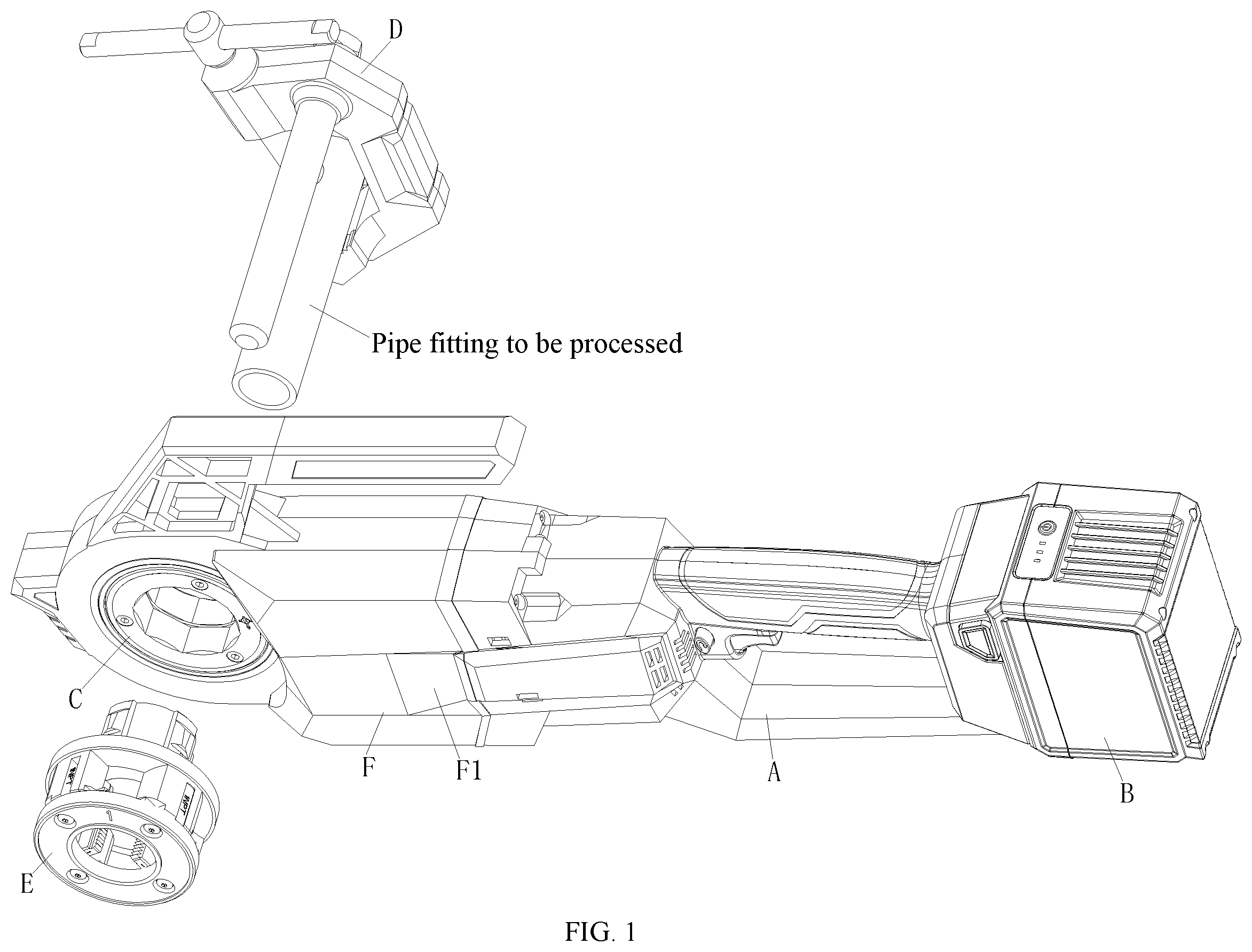
is an exploded view of a handheld lithium battery threading machine according to an embodiment of the present disclosure.
is a schematic structural diagram of a connection relationship of a transmission mechanism according to an embodiment of the present disclosure.
is an exploded view of a motor assembly according to an embodiment of the present disclosure.
is a schematic diagram of an internal structure of a motor assembly according to an embodiment of the present disclosure.
is a perspective view of a motor assembly according to an embodiment of the present disclosure.
is an exploded view of a motor body according to an embodiment of the present disclosure.
is a front view of a motor assembly according to an embodiment of the present disclosure.
is an exploded view of a lithium battery assembly according to an embodiment of the present disclosure.
is a schematic diagram of a mounting structure of a lithium battery assembly according to an embodiment of the present disclosure.
is a sectional view of a buckle mechanism in a lithium battery assembly when in a clamped state according to an embodiment of the present disclosure.
is a sectional view of a buckle mechanism in a lithium battery assembly when in a loosened state according to an embodiment of the present disclosure.
is a perspective view of a support arm body assembly according to an embodiment of the present disclosure.
is an exploded view of a first toothed disc assembly according to an embodiment of the present disclosure.
is a schematic diagram of an assembly structure of a first toothed disc assembly and a die head according to an embodiment of the present disclosure.
is a schematic diagram of an assembly structure of a first toothed disc assembly according to an embodiment of the present disclosure.
is a local view of a first toothed disc assembly according to an embodiment of the present disclosure.
is a local view of a first toothed disc assembly according to an embodiment of the present disclosure.
is a sectional assembly view of a first toothed disc assembly and a die head according to an embodiment of the present disclosure.
is an exploded view of a second toothed disc assembly according to an embodiment of the present disclosure.
is a schematic diagram of an assembly structure of a second toothed disc assembly and a die head according to an embodiment of the present disclosure.
is a front view of a second toothed disc assembly according to an embodiment of the present disclosure.
is a perspective view of a second limiting disc according to an embodiment of the present disclosure.
is a schematic diagram of an assembly structure of a second toothed disc assembly and a die head according to an embodiment of the present disclosure.
is a sectional assembly view of a second toothed disc assembly and a die head according to an embodiment of the present disclosure.
is a perspective view of a handheld lithium battery threading machine according to an embodiment of the present disclosure.
schematically shows a feature of the present disclosure.
In the drawings, motor assembly A, lithium battery assembly B, toothed disc assembly C, support arm body assembly D, a die head E, and gearbox assembly F
motor A 1 , male plug A 2 , main switch A 3 , front handle A 4 , rear handle A 5 , air inlet window A 6 , air outlet window A 7 , and switch reversing rod A 8
motor body A 11 , motor control panel A 12 , signal seven-plug connector A 13 , power three-plug connector A 14 , and signal three-plug connector A 15
motor rotor assembly A 111 , motor stator assembly A 112 , front motor housing A 113 , rear motor housing A 114 , motor positioning recess A 115 , motor positioning lug A 116 , and bearing A 117
battery cover B 1 , battery box B 2 , battery cell B 3 , battery control panel B 4 , buckle mechanism B 5 , female plug B 6 , battery limiting recess B 7 , and battery limiting lug B 8
buckle button B 51 , buckle pressure spring B 52 , buckle positioning pillar B 53 , buckle fixture block B 54 , and buckle slot B 55
first toothed disc C 1 , gasket C 2 , first retainer ring C 3 , eccentric shaft C 4 , and internal octagonal component C 5
first retainer ring body C 31 and retainer ring opening C 32
eccentric shaft body C 41 , eccentric shaft bump C 42 , and eccentric shaft groove C 43
second toothed disc C 6 , pressure spring C 7 , limiting disc C 8 , and second retainer ring C 9
second toothed disc body C 61 and toothed disc limiting groove C 62
limiting disc body C 81 and limiting disc lug C 82
support arm body bracing piece D 1 , support arm body D 2 , support arm body ejector pin D 3 , and support arm body handle D 4
die head clamping groove E 0
gearbox housing F 1 , transmission mechanism F 2 , and housing handle F 3
small arc-tooth conical shaft F 21 , large arc-tooth conical gear F 22 , first-stage gear shaft F 23 , second-stage gear shaft F 24 , third-stage gear shaft F 25 , and transition gear F 26 .
DETAILED DESCRIPTION OF THE EMBODIMENTS
The present disclosure is further described below in detail with reference to the accompanying drawings and the embodiments. The following embodiments describe the present disclosure, but the present disclosure is not limited to these embodiments.
Embodiment
Referring to to , the structure, scale, size, and the like shown in the drawings of this specification are only used to describe the content disclosed in the specification and for those skilled in the art to understand and read, which are not used to limit the limitations for implementing the present disclosure and thus are not technically substantial. Any structural modification, scaling relation change, or size adjustment made without affecting the effects and objectives that can be achieved by the present disclosure shall fall within the scope that can be encompassed by the technical content disclosed in the present disclosure. Moreover, as used herein, the terms such as “upper”, “lower”, “left”, “right”, “middle”, and “a/an” are merely employed for ease of description and not intended to limit the scope of the present disclosure. The change or adjustment of the relative relationships shall be deemed as falling within the scope of the present disclosure without substantial alteration of technical contents.
In this embodiment, the handheld lithium battery threading machine includes a die head E, a motor assembly A, a lithium battery assembly B, a toothed disc assembly C, a support arm body assembly D, and a gearbox assembly F. The lithium battery assembly B is connected to the motor assembly A. The motor assembly A and the toothed disc assembly C are respectively mounted at both ends of the gearbox assembly F. The die head E is mounted on the toothed disc assembly C, and the support arm body assembly D is mounted on the gearbox assembly F and matched with the die head E.
Specifically, as shown in , the handheld lithium battery threading machine includes the motor assembly A, the lithium battery assembly B, the toothed disc assembly C, the support arm body assembly D, the die head E, and the gearbox assembly F. As a core component of the handheld lithium battery threading machine, the motor assembly A plays the role of connecting the front and the rear, the front end thereof is fixedly connected to the gearbox assembly F, and the rear end thereof is provided with the pluggable lithium battery assembly B, and these three components constitute a body of the handheld threading machine. This body can be used as a field driving device with a certain positioning aid. The support arm body assembly D is fixed and clamped on a pipe to be processed, the die head E is mounted on the toothed disc assembly C, and the toothed disc assembly C is mounted on the gearbox assembly F.
As shown in , the main function of the motor assembly A is to output a torque. The main function of the lithium battery assembly B is to provide kinetic energy for the motor assembly A. The gearbox assembly F is to turn the torque outputted by the motor assembly A by 90 degrees. After deceleration, the torque is outputted by the toothed disc assembly C.
The main function of the support arm body assembly D is to be easily fixed on the pipe to be processed, and a support arm body bracing piece D 1 is inserted into a support hole of the gearbox assembly F to provide radial positioning for the gearbox assembly F so as to restrain a reverse torque generated by threading.
The die head E is inserted into the toothed disc assembly C, and its function is to produce pipe external threads on the pipe to be processed under the rotation of the toothed disc assembly C.
In this embodiment, the motor assembly A includes a motor A 1 , a male plug A 2 , a main switch A 3 , a handle, an air inlet window A 6 , and an air outlet window A 7 . The motor A 1 , the male plug A 2 , and the main switch A 3 are all mounted on the handle. The air inlet window A 6 and the air outlet window A 7 are both arranged on the handle. The motor A 1 is connected to the male plug A 2 and the main switch A 3 . The male plug A 2 is connected to a female plug B 6 of the lithium battery assembly B, and the main switch A 3 is connected to a switch reversing rod A 8 .
In this embodiment, the handle includes a front handle A 4 and a rear handle A 5 , where the front handle A 4 is connected to the rear handle A 5 . Each of the front handle A 4 and the rear handle A 5 is provided with the air inlet window A 6 and the air outlet window A 7 .
In this embodiment, the motor A 1 includes a motor body A 11 , a motor control panel A 12 , a signal seven-plug connector A 13 , a power three-plug connector A 14 , and a signal three-plug connector A 15 . Both the motor body A 11 and the motor control panel A 12 are mounted in the handle. The motor body A 11 is connected to the motor control panel A 12 through the signal seven-plug connector A 13 and the power three-plug connector A 14 . The motor control panel A 12 is connected to the main switch A 3 through the signal three-plug connector A 15 , and the motor control panel A 12 is connected to the male plug A 2 .
In this embodiment, the motor body A 11 is a brushless motor. The motor body A 11 includes a motor rotor assembly A 111 , a motor stator assembly A 112 , a motor housing, a motor positioning recess A 115 , a motor positioning lug A 116 , and a bearing A 117 . The motor stator assembly A 112 is sleeved outside the motor rotor assembly A 111 , and both the motor rotor assembly A 111 and the motor stator assembly A 112 are mounted in the motor housing.
In this embodiment, the motor positioning recess A 115 is arranged on an outer wall of the motor stator assembly A 112 . The motor positioning lug A 116 is arranged on an inner wall of the motor housing and located in the motor positioning recess A 115 . Both ends of the motor rotor assembly A 111 are mounted on the motor housing through the bearing A 117 . The motor body A 11 is mounted on a gearbox housing F 1 of the gearbox assembly F.
In this embodiment, the motor housing includes a front motor housing A 113 and a rear motor housing A 114 . The front motor housing A 113 is connected to the rear motor housing A 114 , and each of an inner wall of the front motor housing A 113 and an inner wall of the rear motor housing A 114 is provided with the motor positioning lug A 116 .
Specifically, the motor assembly A includes a motor A 1 , a male plug A 2 , a main switch A 3 , a front handle A 4 , and a rear handle A 5 . The motor A 1 includes two parts, namely a motor body A 11 and a motor control panel A 12 . The motor body A 11 , the motor control panel A 12 , the male plug A 2 , and the main switch A 3 are mounted in the front handle A 4 and the rear handle A 5 in a limited manner.
The motor body A 11 is connected to the motor control panel A 12 through the signal seven-plug connector A 13 and the power three-plug connector A 14 . That is to say, between the motor body A 11 and the motor control panel A 12 , a signal line and a power line of the motor body A 11 and the motor control panel A 12 are respectively connected by the signal seven-plug connector A 13 and the power three-plug connector A 14 . The motor control panel A 12 is connected to the main switch A 3 through the signal three-plug connector A 15 . That is to say, there is a signal three-plug male connector on the motor control panel A 12 , which is communicated with a three-plug female connector of the main switch A 3 .
The motor housing of the motor body A 11 is fixed on the gearbox assembly F through four hexagon socket cap screws (MX 20 ).
The motor body A 11 includes a motor rotor assembly A 111 , a motor stator assembly A 112 , a front motor housing A 113 , a rear motor housing A 114 , etc. The motor rotor assembly A 111 and the motor stator assembly A 112 are positioned and mounted in the front motor housing A 113 and the rear motor housing A 114 . An outer wall of the motor stator assembly A 112 and the motor positioning recess A 115 thereon are matched and positioned with an inner wall of the front motor housing A 113 and an inner wall of the rear motor housing A 114 and the motor positioning lug A 116 thereon, so as to ensure the coaxiality and the axial position of the motor stator assembly A 112 , and eliminate a radial torque generated by the motor stator assembly A 112 . The bearings A 117 at both ends of the motor rotor assembly A 111 are matched and positioned with bearing inner holes on the front motor housing A 113 and the rear motor housing A 114 , so as to ensure the coaxility and the axial position of the motor rotor assembly A 111 with the front motor housing A 113 and the rear motor housing A 114 . The front motor housing A 113 and the rear motor housing A 114 are connected together through eight cross recessed pan head tapping screws (four ST2.2X20 and four ST2.9X15).
The motor body A 11 is fixed on the gearbox assembly F and is also located in a closed space formed between the front handle A 4 and the rear handle A 5 on the gearbox assembly F. The motor control panel A 12 is also located in this space, as shown in . When the motor body A 11 starts to work and rotate, the fan on the motor rotor assembly A 111 can generate airflow, and air enters the closed space from the air inlet window A 6 on the front handle A 4 and the rear handle A 5 and then is exhausted from the air outlet window A 7 on the front handle A 4 and the rear handle A 5 , so as to dissipate heat of the motor body A 11 and the motor control panel A 12 .
In this embodiment, the lithium battery assembly B includes a battery cover B 1 , a battery box B 2 , a battery cell B 3 , a battery control panel B 4 , two buckle mechanisms B 5 , a female plug B 6 , a battery limiting recess B 7 , and a battery limiting lug B 8 . The female plug B 6 is arranged on the battery control panel B 4 . The battery cell B 3 is connected to the battery control panel B 4 . Both the battery cell B 3 and the battery control panel B 4 are mounted in the battery box B 2 . The battery cover B 1 is mounted on the battery box B 2 . The two buckle mechanisms B 5 are both mounted on the battery cover B 1 . The battery limiting recess B 7 is arranged on the handle of the motor assembly A, and the battery limiting lug B 8 is arranged on the battery cover B 1 and located in the battery limiting recess B 7 .
In this embodiment, each buckle mechanism B 5 includes a buckle button B 51 , a buckle pressure spring B 52 , a buckle positioning pillar B 53 , a buckle fixture block B 54 , and a buckle slot B 55 . The buckle button B 51 is mounted on the battery cover B 1 . The buckle positioning pillar B 53 and the buckle fixture block B 54 are both arranged on the buckle button B 51 . The buckle pressure spring B 52 is sleeved on the buckle positioning pillar B 53 and provided with two ends in a butt joint with the battery cover B 1 and the buckle button B 51 . The buckle slot B 55 is arranged on a side wall of the battery limiting recess B 7 , and the buckle fixture block B 54 is located in the buckle slot B 55 .
Specifically, the lithium battery assembly B includes a battery cover B 1 , a battery box B 2 , a battery cell B 3 , a battery control panel B 4 , buckle mechanisms B 5 , and a female plug B 6 . The buckle mechanisms B 5 are mounted in the battery cover B 1 in a limited manner. The battery cell B 3 and the battery control panel B 4 are placed in the battery box B 2 , and the battery cover B 1 and the battery box B 2 are connected together through four cross recessed pan head tapping screws.
As shown in , the lithium battery assembly B is positioned and inserted on the motor assembly A through the battery limiting lug B 8 on the battery cover B 1 and the battery limiting recess B 7 on the front handle A 4 and the rear handle A 5 . It is inserted during operation and pulled out during charging.
As shown in , this state is a working state of the lithium battery assembly B. The buckle fixture block B 54 is limited in the buckle slot B 55 of the front handle A 4 and the rear handle A 5 , such that the lithium battery assembly B cannot be pulled out. At this time, the male plug A 2 of the motor assembly A is inserted into the female plug B 6 on the battery control panel B 4 to connect the lithium battery assembly B to a power supply of the motor A 1 .
As shown in , when the buckle button B 51 is pressed down, the buckle fixture block B 54 on the buckle button B 51 is separated from the buckle slot B 55 of the front handle A 4 and the rear handle A 5 , such that the lithium battery assembly B can be pulled out from the motor assembly A.
In this embodiment, regarding the first toothed disc assembly C (as shown in to ), the toothed disc assembly C includes a first toothed disc C 1 , a gasket C 2 , a first retainer ring C 3 , an eccentric shaft C 4 , and an internal octagonal component C 5 . The gasket C 2 , the first retainer ring C 3 , and the internal octagonal component C 5 are all mounted on the first toothed disc C 1 . The gasket C 2 is sleeved outside the first retainer ring C 3 . The two ends of the eccentric shaft C 4 are respectively mounted on the first toothed disc C 1 and an internal octagonal component C 5 , and the first retainer ring C 3 is matched with the eccentric shaft C 4 .
In this embodiment, the first retainer ring C 3 includes a first retainer ring body C 31 and a retainer ring opening C 32 . The retainer ring opening C 32 is arranged on the first retainer ring body C 31 . The eccentric shaft C 4 includes an eccentric shaft body C 41 and an eccentric shaft bump C 42 . The eccentric shaft bump C 42 is arranged on the eccentric shaft body C 41 and located in the retainer ring opening C 32 . An end of the eccentric shaft body C 41 is provided with an eccentric shaft groove C 43 .
In this embodiment, an octagonal hole arranged on the internal octagonal component C 5 is superposed with an octagonal opening arranged on the first toothed disc C 1 . The first retainer ring C 3 is clamped in a die head clamping groove E 0 of the die head E. The eccentric shaft bump C 42 is arranged as an elliptical structure. When both ends of a long shaft of the eccentric shaft bump C 42 are in contact with the retainer ring opening C 32 , the first retainer ring body C 31 is separated from the die head clamping groove E 0 . When both ends of a short shaft of the eccentric shaft bump C 42 are in contact with the retainer ring opening C 32 , the first retainer ring body C 31 is clamped with the die head clamping groove E 0 .
Specifically, the gasket C 2 , the first retainer ring C 3 , the eccentric shaft C 4 , and the internal octagonal component C 5 are all mounted in the first toothed disc C 1 through three hexagon socket cap screws. A cylindrical pin (5×10) limits the first toothed disc C 1 and the internal octagonal component C 5 . The eccentric shaft C 4 can rotate, and the diameter of the first retainer ring C 3 is increased or decreased. The function of the toothed disc assembly is to provide a torque for the die head E through the internal octagonal component C 5 and perform axial limiting.
The eccentric shaft body C 41 is rotated to make both ends of the long shaft of the eccentric shaft bump C 42 in contact with the retaining ring opening C 32 . The first retainer ring body C 31 can be expanded, and the die head E can be mounted on the toothed disc assembly. The eccentric shaft body C 41 is rotated again to make both ends of the short shaft of the eccentric shaft bump C 42 in contact with the retaining ring opening C 32 . The diameter of the first retainer ring body C 31 is decreased, and the first retainer ring body C 31 can be clamped into the die head clamping groove E 0 .
As shown in , when the eccentric shaft C 4 is located at an open position shown in this figure, it makes the inner diameter of the first retainer ring C 3 increased, such that the die head E can be mounted on the toothed disc assembly.
As shown in , when the eccentric shaft C 4 is located at a closed position shown in this figure, it makes the inner diameter of the first retainer ring C 3 decreased and the first retainer ring C 3 recessed into the die head clamping groove EO of the die head E, so as to limit the axial movement of the die head E.
In this embodiment, regarding the second toothed disc assembly C (as shown in to ), the toothed disc assembly C includes a second toothed disc C 6 , a pressure spring C 7 , a limiting disc C 8 , and a second retainer ring C 9 . The limiting disc C 8 is rotatably mounted on the second toothed disc C 6 through the second retainer ring C 9 , and the two ends of the pressure spring C 7 respectively abut against the second toothed disc C 6 and the limiting disc C 8 .
In this embodiment, the second toothed disc C 6 includes a second toothed disc body C 61 and a toothed disc limiting groove C 62 . The toothed disc limiting groove C 62 is arranged on the second toothed disc body C 61 . The limiting disc C 8 includes a limiting disc body C 81 and a limiting disc lug C 82 . The limiting disc lug C 82 is arranged on the limiting disc body C 81 and located in the toothed disc limiting groove C 62 . The pressure spring C 7 is located in the toothed disc limiting groove C 62 , and both ends of the pressure spring C 7 respectively abut against the toothed disc limiting groove C 62 and the limiting disc lug C 82 .
In this embodiment, an octagonal hole arranged on the limiting disc C 8 is superposed with or staggered from an octagonal opening arranged on the second toothed disc C 6 . The limiting disc C 8 is clamped in the die head clamping groove EO of the die head E. When the octagonal hole arranged on the limiting disc C 8 is superposed with the octagonal opening arranged on the second toothed disc C 6 , the limiting disc body C 81 is separated from the die head clamping groove E 0 . When the octagonal hole arranged on the limiting disc C 8 is separated from the octagonal opening arranged on the second toothed disc C 6 , the limiting disc body C 81 is clamped in the die head clamping groove E 0 .
Specifically, the pressure spring C 7 is placed in the toothed disc limiting groove C 62 of the second toothed disc C 6 . The limiting disc C 8 and the second retainer ring C 9 are mounted on the second toothed disc C 6 through three cross countersunk head screws, and the limiting disc lug C 82 on the limiting disc C 8 is located in the toothed disc limiting groove C 62 . Moreover, both ends of the pressure spring C 7 respectively abut against a side wall of the toothed disc limiting groove C 62 and the limiting disc lug C 82 . The limiting disc C 8 can rotate counterclockwise on the second toothed disc C 6 in a limited manner, and the pressure spring C 7 can make the limiting disc C 8 position at a closed position.
As shown in , the elastic force of the pressure spring C 7 can be overcome with a hand, such that the limiting disc C 8 rotates in the OPEN direction. The octagonal hole of the second toothed disc C 6 will be superposed with the octagonal hole of the limiting disc C 8 . At this time, the die head E can be mounted on the toothed disc assembly.
As shown in , after the die head E can be mounted on the toothed disc assembly, the limiting disc C 8 is loosened. Under the action of the pressure spring C 7 , the octagonal hole of the limiting disc C 8 will be staggered from the octagonal hole of the second toothed disc C 6 . An edge of the octagonal hole of the limiting disc C 8 is clamped in the die head clamping groove EO of the die head E to axially limit the die head E.
In this embodiment, the gearbox assembly F includes a gearbox housing F 1 and a transmission mechanism F 2 . A housing handle F 3 is provided on the gearbox housing F 1 . The transmission mechanism F 2 is mounted in the gearbox housing F 1 and provided with two ends that fit with the motor assembly A and the toothed disc assembly C.
In this embodiment, the transmission mechanism F 2 includes a small arc-tooth conical shaft F 21 , a large arc-tooth conical gear F 22 , a first-stage gear shaft F 23 , a second-stage gear shaft F 24 , a third-stage gear shaft F 25 , and a transition gear F 26 . The small arc-tooth conical shaft F 21 is mounted on the motor A 1 of the motor assembly A and engaged with the large arc-tooth conical gear F 22 . The large arc-tooth conical gear F 22 is mounted on the first-stage gear shaft F 23 . The first-stage gear shaft F 23 is engaged with the second-stage gear shaft F 24 . The second-stage gear shaft F 24 is engaged with the third-stage gear shaft F 25 . The third-stage gear shaft F 25 is engaged with the transition gear F 26 . The transition gear F 26 is engaged with the toothed disc assembly C.
In this embodiment, the support arm body assembly D includes a support arm body bracing piece D 1 , a support arm body D 2 , a support arm body ejector pin D 3 , and a support arm body handle D 4 . The support arm body bracing piece D 1 and the support arm body ejector pin D 3 are both mounted on the support arm body D 2 , and the support arm body handle D 4 is mounted on the support arm body ejector pin D 3 .
In this embodiment, the threading method of a handheld lithium battery threading machine includes the following steps:
S 1 , preparation before work, specifically as follows:
S 11 , fix a support arm body assembly D on a pipe fitting to be processed, as shown in , rotate a support arm body handle D 4 clockwise, such that a support arm body ejector pin D 3 can move toward the pipe fitting, and forcedly rotate the support arm body handle D 4 to fix the pipe fitting between a support arm body D 2 and the support arm body ejector pin D 3 ; and
S 12 , place a die head E into a toothed disc assembly C, as shown in , sleeve an inner hole of the die head E on the pipe fitting by holding a housing handle F 3 with one hand, align a support arm body bracing piece D 1 to a support hole of a gearbox housing F 1 , and push the handheld lithium battery threading machine to the pipe fitting with the other hand by taking a point B as a stress point to enable an end surface of the pipe fitting to be in contact with a die of the die head E; and
S 2 , working stage, specifically as follows:
S 21 , spray a little thread-cutting oil for threading to the pipe fitting through a gap of the die head E with a thread-cutting oil gun; and
S 22 , press an counterclockwise marked end (right-handed threads, and left-handed threads are opposite) of a switch reversing rod A 8 , hold a point A on a handle of a motor assembly A with one hand, pull up a main switch A 3 with a forefinger (the forefinger cannot loosen the button, or the work is stopped) to start the work of a motor body A 11 , drive the toothed disc assembly C to rotate counterclockwise, press the point B with the other hand, apply a little force toward the pipe fitting at the point A and the point B with the two hands, such that the die on the die head E can process threads on the pipe fitting, apply no force with the two hands after 0.5 to 1 turn of threads is processed, intermittently spray the thread-cutting oil for threading to the pipe fitting through the gap of the die head at this time, loosen the forefinger that pulls up the main switch A 3 when an end surface of the pipe fitting is flush with an end surface of the die of the die head E to stop the work of the motor body A 11 , press a clockwise marked end of the switch reversing rod A 8 , hold the point A on the handle of the motor assembly A, pull up the main switch A 3 with the forefinger to enable the motor body A 11 to drive the toothed disc assembly C and the die head E to rotate clockwise, such that the die head E is withdrawn from the pipe fitting; and rotate a support arm body handle D 4 counterclockwise to separate a support arm body ejector pin D 3 from the pipe fitting, and take down the support arm body assembly D to complete processing of pipe external threads of the pipe fitting once.
In addition, it should be noted that the specific embodiments described in this specification may have parts and components with different shapes and names, and the above content described in this specification is only an illustration of the structure of the present disclosure. All equivalent changes or simple changes made according to the structure, features and principles described in the patent concept of the present disclosure are included in the protection scope of the patent of the present disclosure. Various modifications or supplementations of the specific embodiments described or substitutions in a similar manner made by those skilled in the art without departing from the concept of the present disclosure or going beyond the scope as defined in the appended claims should fall within the protection scope of the present disclosure.
Figures (17)
Citations
This patent cites (8)
- US4642002
- US2019/0283157
- US2020/0189017
- US2022/0193804
- US2022/0362869
- US2119981
- US2112585
- USWO-2017/189786