Abstract
A cylinder that kneads an injection material, a heat insulating cover that covers a side surface of the cylinder, the heat insulating cover including a first end portion and a second end portion, a heater arranged between the heat insulating cover and the cylinder, the heater heating a first region of the cylinder, and a first heat pipe that thermally connects the first region and a second region to each other, the second region being different from the first region, are provided. The heat insulating cover includes the first end portion and the second end portion through which the injection material passes, and the first region is closer to a midpoint between the first end portion and the second end portion than the second region.
Claims (11)
1 . An injection molding machine comprising: a cylinder that kneads an injection material supplied from outside and supplies the kneaded injection material to the outside; a heat insulating cover that covers a side surface of the cylinder, the heat insulating cover including a first end portion and a second end portion; a heater arranged between the heat insulating cover and the cylinder, the heater heating a first region of the cylinder; and a first heat pipe that thermally connects the first region and a second region of the cylinder to each other, the second region being different from the first region, wherein the first region is closer to a midpoint between the first end portion and the second end portion than the second region.
Show 10 dependent claims
2 . The injection molding machine according to claim 1 , further comprising a cooling apparatus that cools the injection material supplied to the cylinder, wherein the second region is closer to the cooling apparatus than the first region.
3 . The injection molding machine according to claim 1 , further comprising a nozzle that injects the kneaded injection material into a mold, wherein the second region is closer to the nozzle than the first region.
4 . The injection molding machine according to claim 2 , further comprising: a nozzle that injects the kneaded injection material into a mold; and a second heat pipe that thermally connects a third region in inside of the heat insulating cover and the first region to each other, wherein the third region is closer to the nozzle than the first region, and the first region is closer to the midpoint than the third region.
5 . The injection molding machine according to claim 1 , further comprising: a first temperature sensor that detects a temperature of the first region; a second temperature sensor that detects a temperature of the second region; and a controller connected to the first temperature sensor and the second temperature sensor, wherein the controller is configured to obtain the temperature detected by the first temperature sensor, obtain the temperature detected by the second temperature sensor, and perform processing for cutting off thermal connection between the first region and the second region by the first heat pipe when the temperature detected by the first temperature sensor is lower than a first reference value or when the temperature detected by the second temperature sensor is higher than a second reference value, and the first reference value represents a temperature higher than the second reference value.
6 . The injection molding machine according to claim 4 , further comprising: a first temperature sensor that detects a temperature of the first region; a second temperature sensor that detects a temperature of the second region; a third temperature sensor that detects a temperature of the third region; and a controller connected to the first temperature sensor, the second temperature sensor, and the third temperature sensor, wherein the controller is configured to obtain the temperature detected by the first temperature sensor, obtain the temperature detected by the second temperature sensor, obtain the temperature detected by the third temperature sensor, perform processing for cutting off thermal connection between the first region and the second region by the first heat pipe and cutting off thermal connection between the first region and the third region by the second heat pipe when the temperature detected by the first temperature sensor is lower than a first reference value, perform processing for cutting off thermal connection between the first region and the second region by the first heat pipe when the temperature detected by the second temperature sensor is higher than a second reference value, and perform processing for cutting off thermal connection between the first region and the third region by the second heat pipe when the temperature detected by the third temperature sensor is higher than a third reference value, and the first reference value represents a temperature higher than the second reference value and the third reference value.
7 . The injection molding machine according to claim 2 , further comprising a controller that obtains power consumption by the cooling apparatus and adjusts output of the cooling apparatus, wherein the controller is configured to perform processing for cutting off thermal connection between the first region and the second region by the first heat pipe when power consumption by the cooling apparatus is higher than a predetermined threshold value.
8 . The injection molding machine according to claim 5 , wherein the processing for cutting off thermal connection is processing for giving a notification that the first heat pipe is to be disconnected.
9 . The injection molding machine according to claim 5 , further comprising an actuator that changes arrangement of the first heat pipe, wherein the processing for cutting off thermal connection is processing for cutting off thermal connection between the first region and the second region by change in arrangement of the first heat pipe by the actuator.
10 . The injection molding machine according to claim 1 , further comprising: a first heat radiation body arranged closer to the first region than the second region; and a second heat radiation body arranged closer to the second region than the first region, wherein the first heat pipe is thermally connected to the first region with the first heat radiation body being interposed, and thermally connected to the second region with the second heat radiation body being interposed.
11 . The injection molding machine according to claim 1 , further comprising a third heat pipe that thermally connects the first region and the second region to each other.
Full Description
Show full text →
CROSS REFERENCE TO RELATED APPLICATIONS
This nonprovisional application is based on Japanese Patent Application No. 2022-197756 filed with the Japan Patent Office on Dec. 12, 2022, the entire contents of which are hereby incorporated by reference.
BACKGROUND OF THE INVENTION
Field of the Invention
The present disclosure relates to an injection molding machine.
Description of the Background Art
An injection molding machine is used in a factory for molding of a molded article composed of resin such as plastic as a substrate. Patent Literature 1 (Japanese Patent Laying-Open No. 2016-112772) discloses a technique relating to a method of controlling a temperature of a heating cylinder.
The injection molding machine in Patent Literature 1 includes a heating cylinder that melts resin. The heating cylinder in Patent Literature 1 has a side surface covered with a heat insulating cover. A plurality of band heaters are arranged between the side surface of the heating cylinder and the heat insulating cover. In Patent Literature 1, a heat pump circuit in addition to the plurality of band heaters is provided between the side surface of the heating cylinder and the heat insulating cover. When a temperature of the heating cylinder becomes higher than a target temperature, the heat pump circuit cools the inside of the heat insulating cover with cooling fluid.
SUMMARY OF THE INVENTION
In the injection molding machine in Patent Literature 1, the heat insulating cover can suppress abrupt lowering in temperature of the heating cylinder increased in temperature by the plurality of band heaters, due to exposure thereof to outside air. In other words, the heat insulating cover suppresses ready release of heat in the inside thereof to the outside to keep the temperature of the heating cylinder. In the inside of the heat insulating cover, however, heat release is suppressed, which may result in a region less likely to lower in temperature. The region in the inside of the heat insulating cover less likely to lower in temperature may excessively increase in temperature due to turn-on of the heater that heats the cylinder.
The present disclosure was made to solve such a problem, and an object thereof is to provide an injection molding machine that achieves suppression of occurrence of excessive temperature increase in the inside of a heat insulating cover that covers a cylinder.
An injection molding machine according to one embodiment includes a cylinder that kneads an injection material supplied from outside and supplies the kneaded injection material to the outside, a heat insulating cover that covers a side surface of the cylinder, the heat insulating cover including a first end portion and a second end portion, a heater arranged between the heat insulating cover and the cylinder, the heater heating a first region of the cylinder, and a first heat pipe that thermally connects the first region and a second region of the cylinder to each other, the second region being different from the first region. The first region is closer to a midpoint between the first end portion and the second end portion than the second region.
The foregoing and other objects, features, aspects and advantages of this invention will become more apparent from the following detailed description of this invention when taken in conjunction with the accompanying drawings.
BRIEF DESCRIPTION OF THE DRAWINGS
is a diagram of an appearance of an injection molding machine.
is a diagram for illustrating a structure of a heat insulating cover and a cylinder in a first embodiment.
is a perspective view for illustrating a heat radiation plate and a heat pipe.
is a first diagram showing a temperature detected by a temperature sensor and a duty ratio of a heater.
is a second diagram showing the temperature detected by the temperature sensor and the duty ratio of the heater.
shows a first example of control for cutting off thermal connection by a heat pipe.
shows a second example of control for cutting off thermal connection by the heat pipe.
is a diagram for illustrating a structure of the heat insulating cover and the cylinder in a second embodiment.
shows exemplary control for cutting off thermal connection by the heat pipe in the second embodiment.
is a diagram for illustrating a structure of the heat insulating cover and the cylinder in a third embodiment.
DESCRIPTION OF THE PREFERRED EMBODIMENTS
An embodiment of the present disclosure will be described in detail below with reference to the drawings. The same or corresponding elements in the drawings have the same reference characters allotted and description thereof will not be repeated.
First Embodiment
<Overall Construction of Injection Molding Machine>
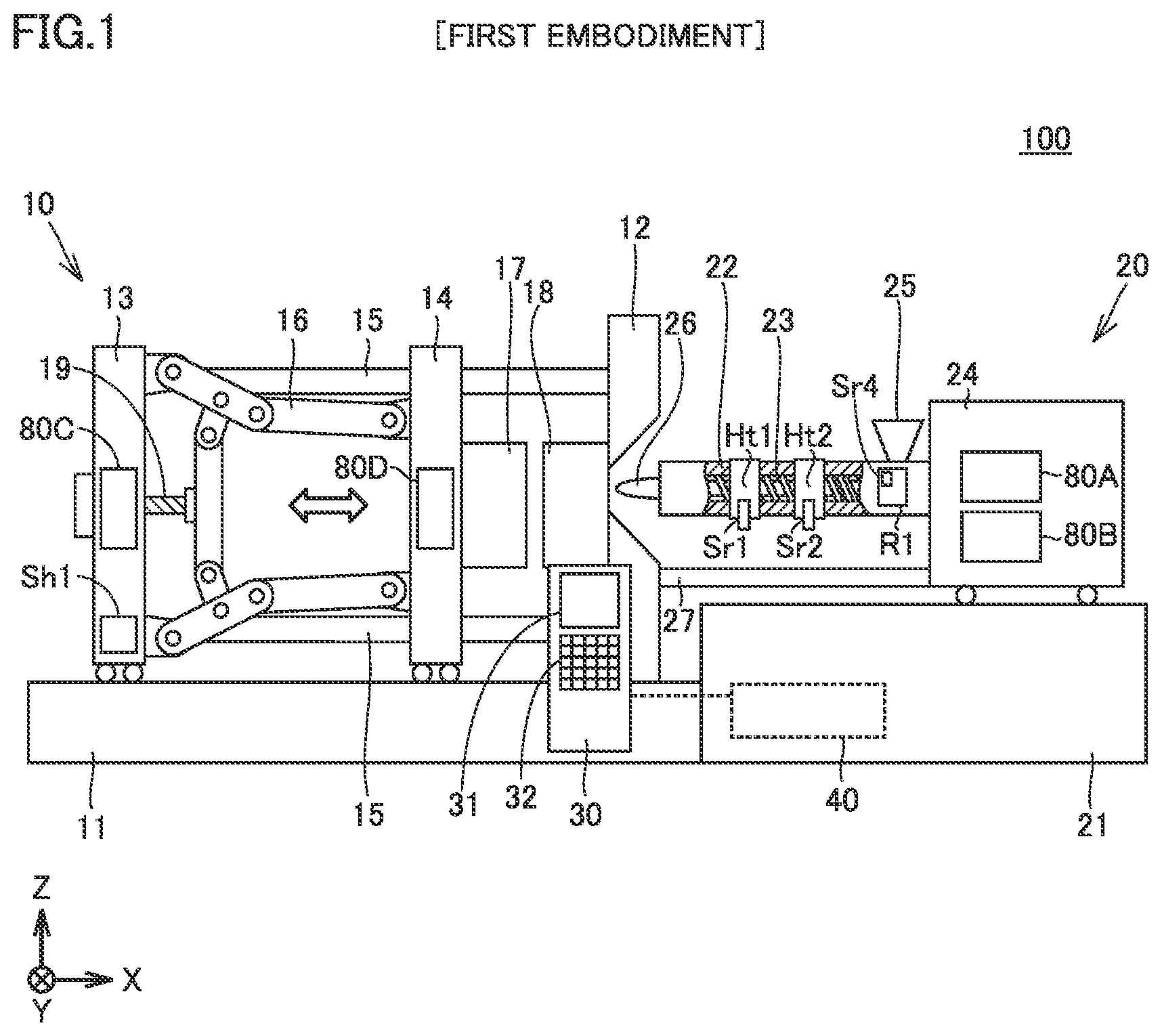
An injection molding machine 100 will be described below with reference to . is a diagram of an appearance of injection molding machine 100 . The overall construction of injection molding machine 100 will be described with reference to .
Injection molding machine 100 is placed on an XY plane. A direction perpendicular to the XY plane is defined as a Z-axis direction. A positive direction along a Z axis in may hereinafter be referred to as an upper surface side or above and a negative direction thereof may be referred to as a lower surface side or below. Though injection molding machine 100 shown in is shown as a lateral injection molding machine, injection molding machine 100 in the present embodiment is not limited to the lateral type but may be a vertical injection molding machine.
Injection molding processing performed by injection molding machine 100 includes a mold closing step, an injection step, a pressure holding step, a mold opening step, a cooling step, an ejection step, and a plasticization step. Injection molding machine 100 repeatedly performs a cycle of the injection molding processing. Injection molding machine 100 can mold a molded article of various shapes and materials, and performs injection molding processing in accordance with the shape and a type of the material of the molded article.
Injection molding machine 100 includes a mold clamping apparatus 10 that clamps a mold, an injection apparatus 20 that melts and injects an injection material, and a control panel 30 . Mold clamping apparatus 10 is arranged on a side of the negative direction along an X axis with respect to injection apparatus 20 .
<Mold Clamping Apparatus>
Mold clamping apparatus 10 in the present embodiment includes a fixed plate 12 , a mold clamping housing 13 , a moving plate 14 , a tie bar 15 , a mold clamping mechanism 16 , molds 17 and 18 , a ball screw 19 , servo motors 80 C and 80 D, and a bed 11 . Bed 11 holds fixed plate 12 , mold clamping housing 13 , moving plate 14 , and the like. Each of mold clamping housing 13 and moving plate 14 is constructed as being slidable over bed 11 in an X-axis direction.
Tie bar 15 is arranged between fixed plate 12 and mold clamping housing 13 , and couples fixed plate 12 and mold clamping housing 13 to each other. Injection molding machine 100 in the first embodiment includes four tie bars 15 . Injection molding machine 100 may include, for example, five or more tie bars 15 , without being limited to four tie bars.
Moving plate 14 is constructed as being slidable in the X-axis direction between fixed plate 12 and mold clamping housing 13 . Mold clamping mechanism 16 is provided between mold clamping housing 13 and moving plate 14 . Mold clamping housing 13 in the present embodiment includes a toggle mechanism. Mold clamping mechanism 16 may include a direct pressure type mold clamping mechanism. The direct pressure type mold clamping mechanism means a mold clamping cylinder.
Servo motor 80 C is provided in mold clamping housing 13 . Servo motor 80 C drives mold clamping mechanism 16 with ball screw 19 being interposed. Ball screw 19 converts rotary motion from servo motor 80 C into linear motion to drive mold clamping mechanism 16 . Molds 17 and 18 are provided between fixed plate 12 and moving plate 14 . Molds 17 and 18 are opened and closed as mold clamping mechanism 16 is driven. In other words, mold 17 is a mold movable by ball screw 19 and mold 18 is a mold fixed by fixed plate 12 .
A step of transition from a state in which molds 17 and 18 are distant from each other to a state in which the molds are in intimate contact with each other is referred to as the “mold closing step.” A step of transition from the state in which molds 17 and 18 are in intimate contact with each other to the state in which the molds are distant from each other is referred to as the “mold opening step.” Servo motor 80 C is used for the mold closing step and the mold opening step.
Injection molding machine 100 performs a step referred to as the “ejection step” after the mold opening step. The ejection step is a step of removing from mold 17 , the solidified injection material after molds 17 and 18 are filled therewith. Specifically, a not-shown pin protrudes as a result of rotation of servo motor 80 D and the molded article in intimate contact with mold 17 is removed. Servo motor 80 D provided in moving plate 14 is used for the ejection step.
<Injection Apparatus>
Injection apparatus 20 includes a cylinder 22 , a drive mechanism 24 , a hopper 25 , an injection nozzle 26 , a nozzle touch apparatus 27 , servo motors 80 A and 80 B, heaters Ht 1 and Ht 2 , temperature sensors Sr 1 and Sr 2 , and a cooling apparatus R 1 .
Cylinder 22 contains a screw 23 that kneads the injection material. Cylinder 22 has an appearance in a columnar shape. More specifically, cylinder 22 has the columnar shape with bottom surfaces on a nozzle side and a hopper side, respectively. A cavity is provided in the inside of cylinder 22 for storage of screw 23 and the injection material.
An opening for transport of the injection material is provided in the bottom surface on each of the nozzle side and the hopper side of cylinder 22 . A surface that connects the two bottom surfaces of cylinder 22 is referred to as a “side surface” of cylinder 22 below. The side surface of cylinder 22 conforms to a curved surface of the columnar shape.
The shape of cylinder 22 is not limited to the columnar shape. Any shape like a post in which screw 23 can be stored such as a shape of a quadrangular prism or a triangular prism may be applicable. Injection molding machine 100 performs a step referred to as the “plasticization step” with the use of screw 23 .
The plasticization step is a step of kneading injected resin by heating of cylinder 22 by heaters Ht 1 and Ht 2 and rotation of screw 23 . Cylinder 22 is heated, for example, to a temperature of 180° C. to 350° C. by heaters Ht 1 and Ht 2 to melt the injection material. Heaters Ht 1 and Ht 2 are each a band heater that covers the side surface of cylinder 22 . Though an example in which injection molding machine 100 includes two heaters Ht 1 and Ht 2 is shown in the first embodiment, in one aspect, injection molding machine 100 may include three or more heaters and may include, for example, ten to thirty heaters. The side surface of cylinder 22 in the first embodiment is further covered with a heat insulating cover. For the sake of simplicity of description, does not show the heat insulating cover, and a structure of cylinder 22 including the heat insulating cover will be described in detail with reference to .
Servo motor 80 B in drive apparatus 24 rotates screw 23 with the X-axis direction being defined as a central axis. In other words, servo motor 80 B is a motor used for the plasticization step. Injection molding machine 100 performs a step referred to as the “injection step” and a step referred to as the “pressure holding step.” The injection step is a step of injecting resin plasticized in the plasticization step into molds 17 and 18 . The pressure holding step is a step of applying a pressure to hold the resin injected in the injection step in molds 17 and 18 . Being driven by servo motor 80 A, screw 23 slides in the negative direction along the X-axis direction. The plasticized resin is thus injected into molds 17 and 18 . Servo motor 80 A is used for the injection step or the pressure holding step.
Hopper 25 is provided on a side of the positive direction along the Z axis of cylinder 22 , and the injection material yet to be plasticized is stored therein. In other words, a granular injection material yet to be molten is stored in hopper 25 . The injection material stored in hopper 25 is transported to the inside of cylinder 22 as screw 23 is driven. Cooling apparatus R 1 is arranged in the vicinity of a path through which the injection material passes from hopper 25 to cylinder 22 .
Cooling apparatus R 1 cools the injection material supplied from hopper 25 into cylinder 22 . Thus, in injection molding machine 100 , melting of the granular injection material stored in hopper 25 by heat generation by heaters Ht 1 and Ht 2 can be suppressed. When the injection material is molten before it reaches cylinder 22 , clogging may occur in a path for transport of the injection material. In other words, in injection molding machine 100 , during the injection molding processing, while heaters Ht 1 and Ht 2 heat cylinder 22 by generating heat, unintended melting of the injection material in hopper 25 can be suppressed with the use of cooling apparatus R 1 . Cooling apparatus R 1 is, for example, a water cooling apparatus that circulates cooling water.
Controller 40 can adjust output of cooling apparatus R 1 . shows a temperature sensor Sr 4 that detects a temperature of cooling water circulated by cooling apparatus R 1 . Controller 40 obtains a temperature detected by temperature sensor Sr 4 and adjusts output of cooling apparatus R 1 in accordance with the obtained temperature.
As shown in , heater Ht 1 heats a region around the center of cylinder 22 and heater Ht 2 heats a region of cylinder 22 closer to cooling apparatus R 1 than heater Ht 1 .
The injection material in cylinder 22 is transported from an end portion in the positive direction along the X axis toward an end portion on the side of the negative direction thereof as screw 23 rotates. In other words, the injection material is initially heated by heater Ht 2 and then heated by heater Ht 1 . The injection material is thus kneaded. Temperature sensors Sr 1 and Sr 2 measure temperatures of regions heated by heaters Ht 1 and Ht 2 , respectively. Temperature sensors Sr 1 and Sr 2 are each implemented, for example, by a thermocouple.
The kneaded injection material is transported to injection nozzle 26 provided at the end portion on the side of the negative direction along the X axis of cylinder 22 . Nozzle touch apparatus 27 slides injection apparatus 20 itself in the X-axis direction to bring injection nozzle 26 into contact with a sprue bush of mold 18 . The injection material is thus injected into mold 18 .
A base 21 is arranged on the side of the positive direction along the X axis of bed 11 and holds drive mechanism 24 or the like. Base 21 contains controller 40 and a not-shown servo amplifier. The servo amplifier supplies electric power to servo motors 80 A to 80 D. Controller 40 obtains detection temperatures detected by temperature sensors Sr 1 and Sr 2 and control heaters Ht 1 and Ht 2 based on the obtained detection temperatures.
<Control Panel>
Control panel 30 includes a display apparatus 31 that shows information on the injection molding processing and an input apparatus 32 that accepts an operation by a user. Control panel 30 is electrically connected to controller 40 . In an example in , control panel 30 is provided on the side of the negative direction along a Y axis of injection molding machine 100 . In one aspect, control panel 30 may be provided separately from injection molding machine 100 , and may be arranged, for example, in a room different from the factory where injection molding machine 100 is arranged.
Display apparatus 31 is implemented, for example, by a display. Input apparatus 32 is implemented, for example, by a plurality of buttons. In one aspect, display apparatus 31 and input apparatus 32 may integrally be provided as a touch panel. Control panel 30 may include a microphone and a speaker and may accept an operation by the user through voice and sound.
<Structure of Heat Insulating Cover and Cylinder>
is a diagram for illustrating a structure of a heat insulating cover C 1 and cylinder 22 in the first embodiment. (A) is a cross-sectional view of heat insulating cover C 1 and cylinder 22 when viewed from the side of the negative direction along the X axis. (B) is a diagram showing heat insulating cover C 1 and cylinder 22 when viewed from the side of the positive direction along the Z axis. The line II-II in (B) shows a position of the cross-section shown in (A) .
Heat insulating cover C 1 covers cylinder 22 such that the side surface of cylinder 22 and heaters Ht 1 and Ht 2 are not exposed to outside air. Heaters Ht 1 and Ht 2 and heat radiation plates B 1 and B 2 are arranged between heat insulating cover C 1 and cylinder 22 . As shown in (A) , cross-sections of screw 23 , cylinder 22 , heaters Ht 1 and Ht 2 , heat radiation plates B 1 and B 2 , and heat insulating cover C 1 are all substantially in a circular shape, and form substantially a concentric shape around a rotation axis Ax of screw 23 . Among screw 23 , cylinder 22 , heaters Ht 1 and Ht 2 , heat radiation plates B 1 and B 2 , and heat insulating cover C 1 , screw 23 is arranged innermost and heat insulating cover C 1 is arranged outermost.
Heaters Ht 1 and Ht 2 heat respective regions Rg 1 and Rg 2 . A target temperature is set for each of regions Rg 1 and Rg 2 . The target temperature set for region Rg 1 may be equal to or different from the target temperature set for region Rg 2 .
As shown in (A) , a recess U 1 is provided on the side of the negative direction along the Y axis and on the side of the negative direction along the Z axis in the cross-section of each of cylinder 22 , heater Ht 2 , heat radiation plate B 2 , and heat insulating cover C 1 . Temperature sensor Sr 2 implemented by the thermocouple is inserted in recess U 1 . Temperature sensor Sr 2 thus detects the temperature of the region heated by heater Ht 2 .
Heat insulating cover C 1 suppresses release of heat generated by heaters Ht 1 and Ht 2 to outside air. Since power consumption by heaters Ht 1 and Ht 2 necessary for melting of the injection material can thus be suppressed in injection molding machine 100 , an energy saving effect can be achieved. Heat insulating cover C 1 is formed, for example, of glass wool.
Heat insulating cover C 1 that covers the side surface of cylinder 22 in the columnar shape is in a shape in conformity with the side surface in the columnar shape. Cylinder 22 includes an end portion where the injection material is supplied from a side of hopper 25 and an end portion where the injection material is supplied to injection nozzle 26 . In other words, the inside of cylinder 22 communicates for passage of the injection material. Heat insulating cover C 1 covers the side surface of cylinder 22 . Heat insulating cover C 1 includes an end portion P 1 on the side of hopper 25 and an end portion P 2 on the side of injection nozzle 26 .
Since heat insulating cover C 1 is in a shape in conformity with the side surface in the columnar shape, it is provided with an opening in each of end portion P 1 and end portion P 2 . Therefore, heat in the inside of heat insulating cover C 1 can be exchanged with an external apparatus or outside air through the openings in end portions P 1 and P 2 . In other words, heat in the inside of heat insulating cover C 1 is released through the openings in end portions P 1 and P 2 . Though shows an example in which heat insulating cover C 1 covers the entire side surface of cylinder 22 , in one aspect, heat insulating cover C 1 may cover only a part of the side surface of cylinder 22 . For example, heat insulating cover C 1 may cover half the side surface of cylinder 22 on the side of hopper 25 , that is, a region from a midpoint Mp 1 to end portion P 1 shown in . In this case, a midpoint between end portion P 1 and end portion P 2 is different from the position shown in .
Midpoint Mp 1 between end portion P 1 and end portion P 2 in the inside of heat insulating cover C 1 is a point where a distance X 1 from end portion P 1 to midpoint Mp 1 is the same as a distance X 2 from end portion P 2 to midpoint Mp 1 . As compared with positions other than midpoint Mp 1 in the inside of heat insulating cover C 1 , midpoint Mp 1 is longest in minimum distance, of a distance to end portion P 1 and a distance to end portion P 2 . Therefore, midpoint Mp 1 is a point in the inside of heat insulating cover C 1 where heat is least likely to be released. Occurrence of excessive temperature increase is more likely in region Rg 1 including midpoint Mp 1 than other regions in the inside of heat insulating cover C 1 .
Therefore, in injection molding machine 100 in the first embodiment, heat pipes HR 1 and HL 1 shown in (B) are used to thermally connect region Rg 1 and region Rg 2 closer to end portion P 1 than region Rg 1 to each other, to thereby transfer heat in region Rg 1 to region Rg 2 . More specifically, one end portions of heat pipes HR 1 and HL 1 are in contact with heat radiation plate B 1 arranged closer to region Rg 1 than region Rg 2 and the other end portions of heat pipes HR 1 and HL 1 are in contact with heat radiation plate B 2 arranged closer to region Rg 2 than Rg 1 .
When the temperature of heat radiation plate B 1 is higher than the temperature of heat radiation plate B 2 , heat pipes HR 1 and HL 1 lower the temperature of heat radiation plate B 1 and increases the temperature of heat radiation plate B 2 . Prescribed liquid as working fluid is sealed in the inside of heat pipes HR 1 ad HL 1 . The working fluid absorbs evaporation latent heat by being heated as a result of heat exchange with heat radiation plate B 1 at one end portions of heat pipes HR 1 and HL 1 to cool heat radiation plate B 1 . The evaporated working fluid moves to the other end portions of heat pipes HR 1 and HL 1 through a pressure-reduced space or a vacuum space, exchanges heat with heat radiation plate B 2 arranged on the other end portion side, releases evaporation latent heat, and is condensed. Thereafter, the condensed working fluid returns to a position where the working fluid has evaporated through an inner wall where a capillary structure (wick) is formed and circulates through flow channels in the inside of heat pipes HR 1 and HL 1 . Heat pipes HR 1 and HL 1 can thus lower the temperature of heat radiation plate B 1 and increase the temperature of heat radiation plate B 2 .
Heat pipes HR 1 and HL 1 in the first embodiment are constructed to temporarily cut off thermal connection between region Rg 1 and region Rg 2 . More specifically, as shown in , heat pipes HR 1 and HL 1 are provided with actuators AR 1 and AL 1 that change arrangement of respective heat pipes HR 1 and HL 1 . In other words, actuators AR 1 and AL 1 move respective heat pipes HR 1 and HL 1 themselves. Actuators AR 1 and AL 1 can change states of heat pipes HR 1 and HL 1 to a state in which they are in contact with both of heat radiation plates B 1 and B 2 and a state in which they are not in contact with at least one of heat radiation plates B 1 and B 2 . Controller 40 has thermal connection by heat pipes HR 1 and HL 1 cut off based on satisfaction of a prescribed condition which will be described later. Heat radiation plates B 1 and B 2 are implemented by heat sinks that enhance heat emission efficiency, and they are made, for example, of a highly thermally conductive metal such as aluminum, iron, or copper.
is a perspective view for illustrating heat radiation plates B 1 and B 2 and the heat pipe. shows heat pipes HU 1 and HD 1 in addition to heat pipe HR 1 shown in (B) . As shown in (B) , heat radiation plates B 1 and B 2 are each in a shape in conformity with the curved surface of the column similarly to heat insulating cover C 1 . Heat pipe HL 1 shown in (B) is not seen in by being hidden by heat radiation plate B 1 .
When viewed from the side of the negative direction along the X axis, heat pipe HR 1 is arranged on the side of the negative direction along the Y axis with respect to screw 23 and heat pipe HL 1 is arranged on the side of the positive direction along the Y axis with respect to screw 23 . When viewed from the side of the negative direction along the X axis, heat pipe HU 1 is arranged on the side of the positive direction along the Z axis with respect to screw 23 and heat pipe HD 1 is arranged on the side of the negative direction along the Z axis with respect to screw 23 . Heat pipes HR 1 , HL 1 , HD 1 , and HU 1 may collectively be referred to as a “heat pipe H 1 ” below.
In the first embodiment, heat pipes H 1 are each in a rod shape and they are identical in shape. Each heat pipe H 1 is in contact with heat radiation plate B 1 and heat radiation plate B 2 . Though a construction in which four heat pipes H 1 are provided is described in the first embodiment, a single heat pipe H 1 or five or more heat pipes H 1 may be provided, without being limited to four heat pipes H 1 .
As shown in , in injection molding machine 100 in the first embodiment, in the inside of heat insulating cover C 1 , region Rg 1 where heat is less likely to be released and region Rg 2 where heat is more likely to be released are thermally connected to each other through heat pipe H 1 . In other words, being provided with heat pipe H 1 , injection molding machine 100 in the first embodiment can lower the temperature of region Rg 1 close to midpoint Mp 1 where heat is least likely to be released and increase the temperature of region Rg 2 in the vicinity of end portion P 1 where heat is more likely to be released than region Rg 1 . The temperatures of the regions heated by respective heaters Ht 1 and Ht 2 in the inside of heat insulating cover C 1 can be brought closer to respective set target temperatures, and excessive temperature increase in the inside of heat insulating cover C 1 that covers cylinder 22 can be suppressed in injection molding machine 100 in the first embodiment.
Furthermore, as shown in , region Rg 2 is closer to cooling apparatus R 1 than region Rg 1 . In other words, region Rg 2 that exchanges heat with heat pipe H 1 with heat radiation plate B 2 being interposed is closer to cooling apparatus R 1 than the first region heated by heater Ht 1 . Therefore, region Rg 2 can exchange heat with cooling apparatus R 1 through end portion P 1 . In other words, the temperature of region Rg 2 may be lowered by cooling by cooling apparatus R 1 .
In order to hold a high temperature of region Rg 2 , watt density of heater Ht 2 may be increased. Provision of a heater high in watt density, however, may lead to increase in cost. When the heater high in watt density is provided, power consumption may also increase. Since heat is transferred from region Rg 1 to region Rg 2 through heat pipe H 1 in injection molding machine 100 in the first embodiment, lowering in temperature of region Rg 2 can be suppressed without providing the heater high in watt density as heater Ht 2 .
In the first embodiment, region Rg 1 is an exemplary “first region” in the present disclosure. Region Rg 2 is an exemplary “second region” in the present disclosure. Heat pipe HR 1 is an exemplary “first heat pipe” in the present disclosure. Heat pipes HU 1 , HD 1 , and HL 1 are each an exemplary “third heat pipe” in the present disclosure. Heat radiation plate B 1 is an exemplary “first heat radiation body” in the present disclosure. Heat radiation plate B 2 is an exemplary “second heat radiation body” in the present disclosure. End portion P 1 is an exemplary “first end portion” in the present disclosure. End portion P 2 is an exemplary “second end portion” in the present disclosure.
Though region Rg 1 includes midpoint Mp 1 in the example described with reference to , region Rg 1 does not have to include midpoint Mp 1 so long as region Rg 1 is closer to midpoint Mp 1 than region Rg 2 . In other words, region Rg 1 should only be a region in the inside of heat insulating cover C 1 where heat is less likely to be released than region Rg 2 .
[Comparison of Change in Temperature]
is a first diagram showing temperatures detected by temperature sensors Sr 1 and Sr 2 and duty ratios of heaters Ht 1 and Ht 2 . An upper tier in shows a graph G 1 of the temperatures detected by temperature sensors Sr 1 and Sr 2 , and a lower tier in shows a graph G 2 of the duty ratios of heaters Ht 1 and Ht 2 . Graph G 1 and graph G 2 share a time axis represented as an abscissa. The duty ratio refers to a ratio of an on period to one cycle, the one cycle being a total of the on period and an off period of the heater. As the duty ratio is higher, the temperature of the heater increases and power consumption also increases. As the duty ratio is lower, the temperature of the heater lowers and power consumption also lowers.
As shown in , heater Ht 1 is arranged at a position for heating of region Rg 1 and heater Ht 2 is arranged at a position for heating of region Rg 2 . In other words, heaters Ht 1 and Ht 2 increase the temperatures of respective regions Rg 1 and Rg 2 . Temperature sensors Sr 1 and Sr 2 detect the temperatures of respective regions Rg 1 and Rg 2 .
As described above, cylinder 22 may be heated, for example, to a temperature of 180° ° C. to 350° C. by heaters Ht 1 and Ht 2 . In other words, a possible range of the target temperature of cylinder 22 is, for example, from 180° C. to 350° C. The target temperature set for cylinder 22 may be different for each of regions Rg 1 and Rg 2 of cylinder 22 as described above.
In the example in , 180° C. is set as the target temperature of cylinder 22 . In other words, a relatively low target temperature is set for cylinder 22 . illustrates suppression by injection molding machine 100 in the first embodiment, of occurrence of excessive temperature increase caused when a relatively low target temperature is set for cylinder 22 .
Lines T 1 and T 2 in graph G 1 represent detection temperatures detected by respective temperature sensors Sr 1 and Sr 2 in the first embodiment. Lines Tz 1 and Tz 2 , on the other hand, represent detection temperatures detected by respective temperature sensors Sr 1 and Sr 2 in a comparative example. An injection molding machine resulting from removal of heat pipe H 1 from injection molding machine 100 in the first embodiment represents the comparative example.
Controller 40 controls heaters Ht 1 and Ht 2 based on the detection temperatures obtained from temperature sensors Sr 1 and Sr 2 . For example, controller 40 controls heaters Ht 1 and Ht 2 under PID control. Controller 40 can thus determine the duty ratios of heaters Ht 1 and Ht 2 in accordance with a difference between the target temperature and detection values from temperature sensors Sr 1 and Sr 2 .
Instead of PID control, when the temperature detected by temperature sensor Sr 1 is lower than the target temperature, controller 40 may increase the duty ratio of heater Ht 1 , and when the temperature detected by temperature sensor Sr 1 is higher than the target temperature, controller 40 may lower the duty ratio of heater Ht 1 . Similarly, when the temperature detected by temperature sensor Sr 2 is lower than the target temperature, controller 40 may increase the duty ratio of heater Ht 2 , and when the temperature detected by temperature sensor Sr 2 is higher than the target temperature, controller 40 may lower the duty ratio of heater Ht 2 .
Lines D 1 and D 2 in graph G 2 represent the duty ratios of respective heaters Ht 1 and Ht 2 in the first embodiment. Lines Dz 1 and Dz 2 , on the other hand, represent the duty ratios of respective heaters Ht 1 and Ht 2 in the comparative example.
In succession, attention is paid to lines Tz 1 and Dz 1 in the comparative example in . In the comparative example without heat pipe H 1 , as the temperatures detected by temperature sensors Sr 1 and Sr 2 are closer to the target temperatures, controller 40 controls the duty ratios of heaters Ht 1 and Ht 2 to lower. In other words, when the target temperature is reached, controller 40 lowers the duty ratio in order to maintain the target temperature.
After the target temperature is exceeded, as shown with line Tz 1 in graph G 1 , a large overshoot occurs in the temperature detected by temperature sensor Sr 1 in the comparative example. This is because region Rg 1 heated by heater Ht 1 is a region where heat is less likely to be released as described above.
As the temperature detected by temperature sensor Sr 1 becomes significantly higher than the target temperature, controller 40 maintains a state in which the duty ratio of heater Ht 1 is 0% as shown with line Dz 1 . In other words, electric power is no longer supplied to heater Ht 1 . Region Rg 1 , however, is the region where heat is less likely to be released. Therefore, in the comparative example, the temperature detected by temperature sensor Sr 1 cannot be lowered to the target temperature and a state in which the temperature is higher than the target temperature is maintained. When the state in which the temperature is higher than the target temperature is maintained, excessive temperature increase may occur in the inside of heat insulating cover C 1 .
Attention is then paid to lines T 1 and D 1 in the first embodiment. In the first embodiment in which heat pipe H 1 is provided, after the temperature detected by temperature sensor Sr 1 becomes higher than the target temperature, an overshoot on line T 1 is smaller than the overshoot on line Tz 1 . This is because heat pipe H 1 transfers heat in region Rg 1 to region Rg 2 . Thus, the first embodiment is earlier in timing of control of the temperature detected by temperature sensor Sr 1 to the target temperature than the comparative example, and maintenance of the state in which the temperature is higher than the target temperature can be suppressed.
is a second diagram showing the temperatures detected by temperature sensors Sr 1 and Sr 2 and the duty ratios of heaters Ht 1 and Ht 2 . An upper tier in shows a graph G 3 of the temperatures detected by temperature sensors Sr 1 and Sr 2 , and a lower tier in shows a graph G 4 of the duty ratios of heaters Ht 1 and Ht 2 . Graph G 3 and graph G 4 share a time axis represented as an abscissa.
In an example in , 350° ° C. is set as the target temperature for cylinder 22 . A relatively high target temperature is set for cylinder 22 . illustrates suppression by injection molding machine 100 in the first embodiment, of occurrence of an insufficient temperature caused when the relatively high target temperature is set for cylinder 22 .
Attention is paid to lines Tz 2 and Dz 2 in the comparative example in . The temperature of region Rg 2 may lower due to such an external factor as drive of cooling apparatus R 1 or change in type of the injection material in the comparative example without heat pipe H 1 . In other words, the temperatures detected by temperature sensors Sr 1 and Sr 2 are lower than the target temperatures. Thus, controller 40 controls the duty ratios of heaters Ht 1 and Ht 2 to increase. In the example in , with lowering in temperature detected by temperature sensor Sr 2 shown with line Tz 2 , controller 40 keeps a state in which the duty ratio of heater Ht 2 has been increased to a maximum value (100%).
In the comparative example, however, heat in heat insulating cover C 1 is released from end portion P 1 due to such an external factor as drive of cooling apparatus R 1 . Therefore, the temperature of region Rg 2 close to end portion P 1 cannot be increased to the target temperature and a state in which the temperature is insufficient is maintained.
Attention is then paid to lines T 2 and D 2 in the first embodiment. In the first embodiment where heat pipe H 1 is provided, after the temperature detected by temperature sensor Sr 2 is lowered, unlike line Tz 2 , the temperature converges to the target temperature at early timing. This is because heat pipe H 1 transfers heat in region Rg 1 to region Rg 2 . Thus, as shown with line T 2 , in the first embodiment, the temperature detected by temperature sensor Sr 2 is controlled to the target temperature earlier than in the comparative example, and maintenance of the state in which the temperature is insufficient in region Rg 2 can be suppressed.
First Control Example
The construction in which heat in region Rg 1 where heat is less likely to be released is transferred through heat pipe H 1 to region Rg 2 where heat is more likely to be released is described with reference to to 5 . Heat pipe H 1 , however, may cause excessive lowering in temperature of region Rg 1 or excessive increase in temperature of region Rg 2 . Processing for cutting off thermal connection by heat pipe H 1 on the occurrence of excessive lowering in temperature of region Rg 1 or excessive increase in temperature of region Rg 2 will be described with reference to .
shows a first example of control for cutting off thermal connection by heat pipe H 1 . A flowchart shown in is stored as a program in a storage that can be accessed by controller 40 . Controller 40 repeats execution of the flowchart shown in while injection molding machine 100 performs the injection molding processing.
Controller 40 obtains the temperature detected by temperature sensor Sr 1 that detects the temperature of region Rg 1 (step S 101 ). Controller 40 obtains the temperature detected by temperature sensor Sr 2 that detects the temperature of region Rg 2 (step S 102 ). Controller 40 compares the temperature detected by temperature sensor Sr 1 obtained in step S 101 with a first reference value, and compares the temperature detected by temperature sensor Sr 2 obtained in step S 102 with a second reference value.
The first reference value is, for example, a lower limit value of the temperature set for region Rg 1 . The first reference value may be larger by a prescribed temperature than the lower limit value of the temperature set for region Rg 1 . The second reference value is, for example, an upper limit value of the temperature set for region Rg 2 . The second reference value may be smaller by a prescribed temperature than the upper limit value of the temperature set for region Rg 2 . Since heat pipe H 1 is provided for transfer of heat from region Rg 1 to region Rg 2 , the first reference value represents a temperature higher than the second reference value.
The first reference value represents a temperature at which insufficiency in heat may occur in region Rg 1 . The second reference value represents a temperature at which excessive temperature increase may occur in region Rg 2 . The first reference value and the second reference value are determined in accordance with the target temperature. Controller 40 determines whether or not the temperature detected by temperature sensor Sr 1 is lower than the first reference value or whether or not the temperature detected by temperature sensor Sr 2 is higher than the second reference value (step S 103 ).
When the temperature detected by temperature sensor Sr 1 is lower than the first reference value or when the temperature detected by temperature sensor Sr 2 is higher than the second reference value (YES in step S 103 ), controller 40 performs processing for cutting off thermal connection by heat pipe H 1 between region Rg 1 and region Rg 2 (step S 104 ). When the temperature detected by temperature sensors Sr 1 is not lower than the first reference value and when the temperature detected by temperature sensor Sr 2 is not higher than the second reference value (NO in step S 103 ), controller 40 quits the process.
The processing for cutting off thermal connection by heat pipe H 1 in step S 104 will be described below. The processing for cutting off thermal connection in step S 104 is processing for driving actuators AR 1 and AL 1 provided in heat pipe H 1 described above. As actuators AR 1 and AL 1 are driven, heat pipe H 1 is no longer in contact with heat radiation plate B 1 or heat radiation plate B 2 . Thermal connection by heat pipe H 1 is thus cut off. In other words, heat in region Rg 1 is no longer transferred to region Rg 2 . Injection molding machine 100 can thus cut off thermal connection between region Rg 1 and region Rg 2 without workloads being imposed on a user. Actuators AR 1 and AL 1 may drive a switching apparatus provided in the flow channel in heat pipe H 1 to thereby stop circulation of working fluid through heat pipe H 1 .
Alternatively, the processing for cutting off thermal connection in step S 104 may be, for example, processing for notifying that heat pipe H 1 is to be disconnected. Specifically, controller 40 notifies the user that heat pipe H 1 is to be disconnected through display apparatus 31 , a not-shown speaker, an indicator, or the like. Thus, injection molding machine 100 can notify the outside of possibility of the insufficient temperature of region Rg 1 or excessive temperature increase in region Rg 2 due to arrangement of heat pipe H 1 .
The processing for cutting off thermal connection in step S 104 may be either processing for cut-off by a disconnection circuit or processing for notifying the user that heat pipe H 1 is to be disconnected, or both of them may simultaneously be performed. Temperature sensor Sr 1 is an exemplary “first temperature sensor” in the present disclosure. Temperature sensor Sr 2 is an exemplary “second temperature sensor” in the present disclosure.
Second Control Example
The control example in which cut-off processing is performed based on comparison of the temperatures detected by temperature sensors Sr 1 and Sr 2 with the first reference value and the second reference value, respectively, is described with reference to . illustrates a control example in which cut-off processing is performed based on power consumption by cooling apparatus R 1 .
As described above, controller 40 can adjust output of cooling apparatus R 1 and adjusts output of cooling apparatus R 1 in accordance with a temperature detected by temperature sensor Sr 4 that detects the temperature of cooling water in cooling apparatus R 1 . Specifically, when the temperature of cooling water increases, controller 40 increases output of cooling apparatus R 1 , and when the temperature of cooling water lowers, controller 40 lowers output of cooling apparatus R 1 . With increase in output of cooling apparatus R 1 , electric power consumed by cooling apparatus R 1 increases.
shows a second example of control for cutting off thermal connection by heat pipe H 1 . A flowchart shown in is stored as a program in a storage that can be accessed by controller 40 . Controller 40 repeats execution of the flowchart shown in while injection molding machine 100 performs the injection molding processing.
Controller 40 obtains power consumption by cooling apparatus R 1 (step S 201 ). In other words, controller 40 obtains output of cooling apparatus R 1 . Output of cooling apparatus R 1 is determined by the number of rotations of the motor for circulation of cooling water.
Controller 40 determines whether or not power consumption by cooling apparatus R 1 is higher than a predetermined threshold value (step S 202 ). When power consumption is higher than the predetermined threshold value (YES in step S 202 ), controller 40 performs the processing for cutting off thermal connection by heat pipe H 1 (step S 203 ) as in step S 104 described with reference to . When power consumption is not higher than the predetermined threshold value (NO in step S 202 ), controller 40 quits the process.
Thus, when the temperature of region Rg 2 excessively increases due to heat pipe H 1 and electric power consumed by cooling apparatus R 1 increases, injection molding machine 100 in the first embodiment can perform the processing for cutting off thermal connection.
Second Embodiment
An injection molding machine in a second embodiment will be described below with reference to . is a diagram for illustrating a structure of heat insulating cover C 1 and cylinder 22 in the second embodiment. Description of a feature in the second embodiment similar to that in the first embodiment will not be repeated.
(A) is a cross-sectional view of heat insulating cover C 1 and cylinder 22 when viewed from the side of the negative direction along the X axis in the second embodiment. (B) is a diagram showing heat insulating cover C 1 and cylinder 22 when viewed from the side of the positive direction along the Z axis in the second embodiment. The line II-II in (B) indicates a position of the cross-section shown in (A) .
In the second embodiment, heat pipes HR 2 and HL 2 are provided in addition to heat pipes HR 1 and HL 1 . Heat pipes HR 2 and HL 2 are collectively referred to as a “heat pipe H 2 ” below. Heat pipe H 2 may include four heat pipes similarly to heat pipe H 1 , or may include five or more heat pipes.
In injection molding machine 100 in the second embodiment, heat pipe H 2 is used to thermally connect region Rg 1 and a region Rg 3 closer to end portion P 2 than region Rg 1 to each other, to thereby transfer heat in region Rg 1 to region Rg 3 . Region Rg 1 is closer to midpoint Mp 1 than region Rg 3 . As shown in , region Rg 3 is closer to injection nozzle 26 than region Rg 1 . Therefore, heat in region Rg 3 tends to be released as a result of heat exchange with injection nozzle 26 through end portion P 2 . A heat radiation plate B 3 and a heater Ht 3 are arranged in region Rg 3 . Injection molding machine 100 further includes a temperature sensor Sr 3 that detects a temperature of region Rg 3 .
As shown in , in injection molding machine 100 in the second embodiment, in the inside of heat insulating cover C 1 , region Rg 1 where heat is less likely to be released and region Rg 3 where heat is more likely to be released are thermally connected to each other through heat pipe H 2 . In other words, being provided with heat pipe H 2 , injection molding machine 100 in the second embodiment can lower the temperature of region Rg 1 including midpoint Mp 1 where heat is least likely to be released and increase the temperature of region Rg 3 in the vicinity of end portion P 2 where heat is more likely to be released than region Rg 1 . The temperatures of the respective regions heated by heaters Ht 1 to Ht 3 in the inside of heat insulating cover C 1 can be close to the set target temperatures, and injection molding machine 100 in the second embodiment can achieve suppression of excessive temperature increase in the inside of heat insulating cover C 1 that covers cylinder 22 .
Heat pipe H 2 is an exemplary “second heat pipe” in the present disclosure. Region Rg 3 is an exemplary “third region” in the present disclosure.
shows exemplary control for cutting off thermal connection by heat pipes H 1 and H 2 in the second embodiment. Controller 40 repeats execution of the flowchart shown in while injection molding machine 100 performs the injection molding processing.
Controller 40 obtains the temperature detected by temperature sensor Sr 1 that detects the temperature of region Rg 1 (step S 301 ). Controller 40 obtains the temperature detected by temperature sensor Sr 2 that detects the temperature of region Rg 2 (step S 302 ). Controller 40 obtains the temperature detected by temperature sensor Sr 3 that detects the temperature of region Rg 3 (step S 303 ). Controller 40 compares the temperature detected by temperature sensors Sr 1 obtained in step S 301 with the first reference value as in step S 101 in .
Controller 40 determines whether or not the temperature detected by temperature sensor Sr 1 is lower than the first reference value (step S 304 ). When the temperature detected by temperature sensor Sr 1 is lower than the first reference value (YES in step S 304 ), controller 40 performs processing for cutting off thermal connection by heat pipes H 1 and H 2 (step S 305 ). Thus, injection molding machine 100 in the second embodiment can suppress the insufficient temperature of region Rg 1 . When the temperature detected by temperature sensor Sr 1 is not lower than the first reference value (NO in step S 304 ), controller 40 compares the temperature detected by temperature sensor Sr 2 obtained in step S 302 with the second reference value. In other words, controller 40 determines whether or not the temperature detected by temperature sensor Sr 2 is higher than the second reference value (step S 306 ). When the temperature detected by temperature sensor Sr 2 is higher than the second reference value (YES in step S 306 ), controller 40 performs processing for cutting off thermal connection by heat pipe H 1 (step S 307 ). Injection molding machine 100 in the second embodiment can thus suppress occurrence of excessive temperature increase in region Rg 2 . When the temperature detected by temperature sensor Sr 2 is not lower than the second reference value (NO in step S 306 ), controller 40 compares the temperature detected by temperature sensor Sr 3 obtained in step S 303 with a third reference value.
The third reference value is, for example, an upper limit value of the temperature set for region Rg 3 . The third reference value may be smaller by a prescribed temperature than the upper limit value of the temperature set for region Rg 3 . Since heat pipe H 2 is provided for transfer of heat from region Rg 1 to region Rg 3 , the first reference value represents a temperature higher than the third reference value.
Controller 40 determines whether or not the temperature detected by temperature sensor Sr 3 is higher than the third reference value (step S 308 ). When the temperature detected by temperature sensor Sr 3 is higher than the third reference value (YES in step S 308 ), controller 40 performs processing for cutting off thermal connection by heat pipe H 2 (step S 309 ). Injection molding machine 100 in the second embodiment can thus suppress occurrence of excessive temperature increase in region Rg 3 . When the temperature detected by temperature sensor Sr 3 is not lower than the third reference value (NO in step S 308 ), controller 40 quits the process. The control example described with reference to can thus be applied also to the construction in the second embodiment by taking into consideration, the detection value from temperature sensor Sr 3 . The flowchart similar to that in the control example described with reference to can be applied as it is to the construction in the second embodiment.
Third Embodiment
An injection molding machine in a third embodiment will be described below with reference to . is a diagram for illustrating a structure of heat insulating cover C 1 and cylinder 22 in the third embodiment. Description of a feature in the third embodiment similar to that in the first and second embodiments will not be repeated.
(A) is a cross-sectional view of heat insulating cover C 1 and cylinder 22 when viewed from the side of the negative direction along the X axis in the third embodiment. (B) is a diagram showing heat insulating cover C 1 and cylinder 22 when viewed from the side of the positive direction along the Z axis in the third embodiment. The line II-II in (B) indicates a position of the cross-section shown in (A) .
Injection molding machine 100 in the third embodiment is different in position of region Rg 2 from the first embodiment. As shown in , region Rg 2 is closer to injection nozzle 26 than region Rg 1 . Therefore, heat in region Rg 2 tends to be radiated through end portion P 2 .
In injection molding machine 100 in the third embodiment, in the inside of heat insulating cover C 1 , region Rg 1 where heat is less likely to be released is thermally connected through heat pipe H 1 to region Rg 2 where heat is more likely to be released. In other words, being provided with heat pipe H 1 , injection molding machine 100 in the third embodiment can lower the temperature of region Rg 1 including midpoint Mp 1 where heat is least likely to be released and increase the temperature of region Rg 2 in the vicinity of end portion P 2 where heat is more likely to be released than region Rg 1 . The temperatures of the regions heated by respective heaters Ht 1 and Ht 2 in the inside of heat insulating cover C 1 can thus be closer to the set temperatures, and injection molding machine 100 in the third embodiment can suppress occurrence of excessive temperature increase in the inside of heat insulating cover C 1 that covers cylinder 22 .
In the third embodiment, heat pipe H 1 is an exemplary “first heat pipe” in the present disclosure. Region Rg 1 is an exemplary “first region” in the present disclosure. Region Rg 2 is an exemplary “second region” in the present disclosure.
Additional Aspects
Illustrative embodiments described above are understood by a person skilled in the art as specific examples of aspects below.
(Clause 1) An injection molding machine in the present disclosure includes a cylinder that kneads an injection material supplied from outside and supplies the kneaded injection material to the outside, a heat insulating cover that covers a side surface of the cylinder, the heat insulating cover including a first end portion and a second end portion, a heater arranged between the heat insulating cover and the cylinder, the heater heating a first region of the cylinder, and a first heat pipe that thermally connects the first region and a second region of the cylinder to each other, the second region being different from the first region. The first region is closer to a midpoint between the first end portion and the second end portion than the second region.
According to injection molding machine 100 described in Clause 1, occurrence of excessive temperature increase in the inside of the heat insulating cover that covers the cylinder can be suppressed. In other words, heat in the first region where heat tends to concentrate because of the heat insulating cover can be transferred to the second region where heat is more likely to be released and excessive temperature increase in the first region can be suppressed.
(Clause 2) The injection molding machine according to Clause 1 further includes a cooling apparatus that cools the injection material supplied to the cylinder. The second region is closer to the cooling apparatus than the first region.
According to injection molding machine 100 described in Clause 2, occurrence of an insufficient temperature of the second region where heat is more likely to be released because of the cooling apparatus can be suppressed.
(Clause 3) The injection molding machine according to Clause 1 further includes a nozzle that injects the kneaded injection material into a mold. The second region is closer to the nozzle than the first region.
According to injection molding machine 100 described in Clause 3, occurrence of the insufficient temperature of the second region where heat is more likely to be released because of the nozzle can be suppressed.
(Clause 4) The injection molding machine according to Clause 2 further includes a nozzle that injects the kneaded injection material into a mold and a second heat pipe that thermally connects a third region in inside of the heat insulating cover and the first region to each other. The third region is closer to the nozzle than the first region and the first region is closer to the midpoint than the third region.
According to injection molding machine 100 described in Clause 4, occurrence of the insufficient temperature of the second region where heat is more likely to be released because of the cooling apparatus and the third region where heat is more likely to be released because of the nozzle can be suppressed.
(Clause 5) The injection molding machine according to any one of Clauses 1 to 4 further includes a first temperature sensor that detects a temperature of the first region, a second temperature sensor that detects a temperature of the second region, and a controller connected to the first temperature sensor and the second temperature sensor. The controller is configured to obtain the temperature detected by the first temperature sensor, to obtain the temperature detected by the second temperature sensor, and to perform processing for cutting off thermal connection between the first region and the second region by the first heat pipe when the temperature detected by the first temperature sensor is lower than a first reference value or when the temperature detected by the second temperature sensor is higher than a second reference value. The first reference value represents a temperature higher than the second reference value.
According to injection molding machine 100 described in Clause 5, when the temperatures detected by the first temperature sensor and the second temperature sensor exceed respective threshold values, a state in which the heat pipe should be disconnected can be detected and cut-off processing can be performed.
(Clause 6) The injection molding machine according to Clause 4 further includes a first temperature sensor that detects a temperature of the first region, a second temperature sensor that detects a temperature of the second region, a third temperature sensor that detects a temperature of the third region, and a controller connected to the first temperature sensor, the second temperature sensor, and the third temperature sensor. The controller is configured to obtain the temperature detected by the first temperature sensor, to obtain the temperature detected by the second temperature sensor, to obtain the temperature detected by the third temperature sensor, to perform processing for cutting off thermal connection between the first region and the second region by the first heat pipe and cutting off thermal connection between the first region and the third region by the second heat pipe when the temperature detected by the first temperature sensor is lower than a first reference value, to perform processing for cutting off thermal connection between the first region and the second region by the first heat pipe when the temperature detected by the second temperature sensor is higher than a second reference value, and to perform processing for cutting off thermal connection between the first region and the third region by the second heat pipe when the temperature detected by the third temperature sensor is higher than a third reference value. The first reference value represents a temperature higher than the second reference value and the third reference value.
According to injection molding machine 100 described in Clause 6, when the temperatures detected by the first temperature sensor to the third temperature sensor exceed respective threshold values, a state in which at least one of the two heat pipes should be disconnected can be detected and cut-off processing can be performed.
(Clause 7) The injection molding machine according to Clause 2 further includes a controller that obtains power consumption by the cooling apparatus and adjusts output of the cooling apparatus. The controller is configured to perform processing for cutting off thermal connection between the first region and the second region by the first heat pipe when power consumption by the cooling apparatus is higher than a predetermined threshold value.
According to injection molding machine 100 described in Clause 7, when the temperature of the second region excessively increases because of the heat pipe, excessive temperature increase of the second region can be detected based on power consumption by the cooling apparatus and processing for cutting off transfer of heat by the heat pipe can be performed.
(Clause 8) In the injection molding machine according to any one of Clauses 5 to 7, the processing for cutting off thermal connection is processing for giving a notification that the first heat pipe is to be disconnected.
According to injection molding machine 100 described in Clause 8, a user can be notified that the heat pipe is to be disconnected.
(Clause 9) The injection molding machine according to any one of Clauses 5 to 7 further includes an actuator that changes arrangement of the first heat pipe. The processing for cutting off thermal connection is processing for cutting off thermal connection between the first region and the second region by change in arrangement of the first heat pipe by the actuator.
According to injection molding machine 100 described in Clause 9, a flow channel in the heat pipe can automatically be cut off without workloads being imposed on a user.
(Clause 10) The injection molding machine according to any one of Clauses 1 to 9 further includes a first heat radiation body arranged closer to the first region than the second region and a second heat radiation body arranged closer to the second region than the first region. The first heat pipe is thermally connected to the first region with the first heat radiation body being interposed and thermally connected to the second region with the second heat radiation body being interposed.
According to injection molding machine 100 described in Clause 10, efficient transfer of heat between the first region and the second region can be promoted with the use of the heat radiation body.
(Clause 11) The injection molding machine according to any one of Clauses 1 to 10 further includes a third heat pipe that thermally connects the first region and the second region to each other.
According to injection molding machine 100 described in Clause 11, efficient transfer of heat between the first region and the second region can be promoted with the use of a plurality of heat pipes.
Though embodiments of the present invention have been described, it should be understood that the embodiments disclosed herein are illustrative and non-restrictive in every respect. The scope of the present invention is defined by the terms of the claims and is intended to include any modifications within the scope and meaning equivalent to the terms of the claims.
Figures (10)
Citations
This patent cites (11)
- US6305923
- US2007/0181537
- US2007/0222125
- US2014/0117573
- US2021/0031423
- US2021/0078230
- US207359513
- US3100472
- USH09262886
- US2016-112772
- US20170067538