Surgical Robotic System with Daisy Chaining
Abstract
A surgical robotic system includes a first robotic arm, a second robotic arm, a control tower, and a surgeon console. The first robotic arm is engaged with a first movable cart. The second robotic arm is engaged with a second movable cart. The control tower is configured to control movement of the first robotic arm. The surgeon console is configured to provide instructions to the control tower. The control tower is electrically coupled to the surgeon console via a first cable. The surgeon console is electrically coupled to the first movable cart via a second cable.
Claims (18)
1 . A surgical robotic system comprising: a first robotic arm engaged with a first movable cart; a second robotic arm engaged with a second movable cart; a control tower configured to control movements of the first robotic arm and the second robotic arm; and a surgeon console configured to provide instructions to the control tower, wherein the control tower is directly electrically coupled to the surgeon console via a first cable, wherein the surgeon console is directly electrically coupled to the first movable cart via a second cable, wherein the control tower is directly electrically coupled to the second robotic arm via a third cable, wherein the control tower is free from a direct electrical coupling with the first movable cart, wherein the surgeon console is free from a direct electrical coupling with the second movable cart, wherein each of the first cable, the second cable, and the third cable is configured to transmit electrical current sufficient for supplying power for surgical procedures, and wherein at least one of the first cable, the second cable or the third cable is configured to transmit electrosurgical current.
13 . A surgical robotic system, comprising: a control tower; a surgeon console directly electrically coupled to the control tower; and a plurality of movable carts, each of which having a robotic arm engaged therewith, and each of which including a battery for supplying power, wherein each movable cart of the plurality of movable carts is electrically coupled to another movable cart of the plurality of movable carts in a daisy chain arrangement, wherein only a first movable cart of the plurality of movable carts is directly electrically coupled to the control tower via a cable which is configured to transmit electrosurgical current, and wherein only a second movable cart of the plurality of movable carts is directly electrically coupled to the surgeon console.
16 . A method of supplying power to a surgical robotic system, comprising: directly electrically coupling a surgeon console with a control tower using a first cable; directly electrically coupling a first movable cart with the surgeon console using a second cable; electrically coupling a second movable cart with the first movable cart using a third cable; and directly electrically coupling the second movable cart with the control tower using a fourth cable, wherein each of the first cable, the second cable, the third cable, and the fourth cable is configured to transmit electrosurgical current.
Show 15 dependent claims
2 . The surgical robotic system according to claim 1 , wherein the first movable cart is electrically coupled to the second movable cart.
3 . The surgical robotic system according to claim 2 , further comprising a third robotic arm engaged with a third movable cart, wherein each of the first movable cart and the second movable cart is electrically coupled to the third movable cart, wherein the surgeon console is free from a direct electrical coupling with the third movable cart.
4 . The surgical robotic system according to claim 2 , further comprising an endoscopic camera mechanically coupled to the first robotic arm, and a surgical instrument mechanically coupled to the second robotic arm.
5 . The surgical robotic system according to claim 1 , wherein the control tower includes a power supply system therein.
6 . The surgical robotic system according to claim 5 , wherein the surgeon console is directly electrically coupled to the power supply system.
7 . The surgical robotic system according to claim 5 , wherein the power supply system includes a power ingress module, an electrical main configured to supply alternating current, an isolation transformer, and at least one uninterruptible power supply coupled to the isolation transformer.
8 . The surgical robotic system according to claim 7 , wherein the uninterruptible power supply is coupled to a tower power supply chassis.
9 . The surgical robotic system according to claim 8 , wherein the tower power supply chassis includes a first power supply configured to provide a regulated DC output to the surgeon console via the first cable and a first connector.
10 . The surgical robotic system according to claim 9 , wherein the surgeon console includes a second power supply configured to provide a regulated DC output to the first movable cart via the second cable and a second connector.
11 . The surgical robotic system according to claim 1 , further comprising an endoscopic camera mechanically coupled to the first robotic arm.
12 . The surgical robotic system according to claim 1 , wherein each of the first robotic arm, the second robotic arm, the control tower, and the surgeon console is directly electrically coupled to two other of the first robotic arm, the second robotic arm, the control tower, and the surgeon console in a closed loop daisy chain arrangement.
14 . The surgical robotic system according to claim 13 , wherein each of the control tower, the surgeon console, and each movable cart of the plurality of movable carts is electrically coupled to two other of the control tower, the surgeon console, and each movable cart of the plurality of movable carts in a closed loop daisy chain arrangement.
15 . The surgical robotic system according to claim 13 , wherein the control tower includes a power supply, and wherein the surgeon console includes a power supply.
17 . The method according to claim 16 , wherein the surgeon console is only directly electrically coupled to the control tower and the first movable cart.
18 . The surgical robotic system according to claim 16 , wherein each of the control tower, the surgeon console, the first movable cart, and the second movable cart is directly electrically coupled to exactly two other of the control tower, the surgeon console, the first movable cart, and the second movable cart in a closed loop daisy chain arrangement.
Full Description
Show full text →
CROSS-REFERENCE TO RELATED APPLICATIONS
This application claims the benefit of and priority to U.S. Provisional Patent Application No. 63/248,005, filed on Sep. 24, 2021 and to U.S. Provisional Patent Application No. 63/306,234, filed on Feb. 3, 2022. The entire disclosures of each of the foregoing applications are incorporated by reference herein.
BACKGROUND
Surgical robotic systems are currently being used in minimally invasive medical procedures. Some surgical robotic systems include a control tower, a surgeon console, and at least one movable cart having a surgical instrument coupled thereto. In use, each component of the surgical robotic system requires power to be able to function. Additionally, the surgeon or user may want to position the components of the surgical robotic system at different locations in the operating room, for instance. Further, minimizing lengths of power cords and/or extension cords, in addition to having flexibility in positioning the components of the surgical robotic system may be helpful.
SUMMARY
The disclosure relates to a surgical robotic system including a first robotic arm, a second robotic arm, a control tower, and a surgeon console. The first robotic arm is engaged with a first movable cart. The second robotic arm is engaged with a second movable cart. The control tower is configured to control movements of the first robotic arm. The surgeon console is configured to provide instructions to the control tower. The control tower is electrically coupled to the surgeon console via a first cable. The surgeon console is electrically coupled to the first movable cart via a second cable.
In aspects, first movable cart may be electrically coupled to the second movable cart via a third cable. In further aspects, the surgical robotic system may include a third robotic arm engaged with a third movable cart. The second movable cart may be electrically coupled to the third movable cart via a fourth cable.
In aspects, the control tower may include a power supply system therein. In further aspects, the surgeon console may be directly electrically coupled to the power supply system with the first cable, and the first movable cart may be directly electrically coupled to the surgeon console with the second cable. In further aspects, the power supply system may include a power ingress module, an electrical main configured to supply alternating current, an isolation transformer, and at least one uninterruptible power supply coupled to the isolation transformer. In further aspects, the uninterruptible power supply may be coupled to a tower power supply chassis. In further aspects, the tower power supply chassis may include a first power supply configured to provide a regulated DC output to the surgeon console via the first cable and a first connector. In further aspects, the surgeon console may include a second power supply configured to provide a regulated DC output to the first movable cart via the second cable and a second connector. In further aspects, the surgical robotic system may include a second robotic arm engaged with a second movable cart. The first movable cart may include a third power supply configured to provide a regulated DC output to the second movable cart via a third cable and a third connector.
In aspects, the surgical robotic system may include an endoscopic camera mechanically coupled to the first robotic arm. In further aspects, the surgical robotic system may include a surgical instrument mechanically coupled to a second robotic arm engaged with a second movable cart.
The disclosure also relates to a surgical robotic system includes a control tower and a plurality of components. The plurality of components includes a surgeon console, and a plurality of movable carts. Each movable cart of the plurality of movable carts has a robotic arm engaged therewith. Each component of the plurality of components is electrically coupled to another component of the plurality of components in a daisy chain arrangement.
In aspects, one component of the plurality of components may be electrically coupled to the control tower.
In aspects, each component of the plurality of components may include a power supply. In further aspects, the control tower may include a power supply. In further aspects, the surgical robotic system may include a first cable interconnecting the power supply of the control tower with one component of the plurality of components.
In aspects, each component of the plurality of components is electrically coupled to another component of the plurality of components in a closed loop daisy chain arrangement.
The disclosure also relates to a method of supplying power to a surgical robotic system including electrically coupling a surgeon console with a control tower using a first cable, electrically coupling a first movable cart with the surgeon console using a second cable, and electrically coupling a second movable cart with the first movable cart using a third cable.
In aspects, the method may include electrically coupling a power supply of a third movable cart with a power supply of the second movable cart using a fourth cable.
BRIEF DESCRIPTION OF THE DRAWINGS
Various aspects of the present disclosure are described herein with reference to the drawings wherein:
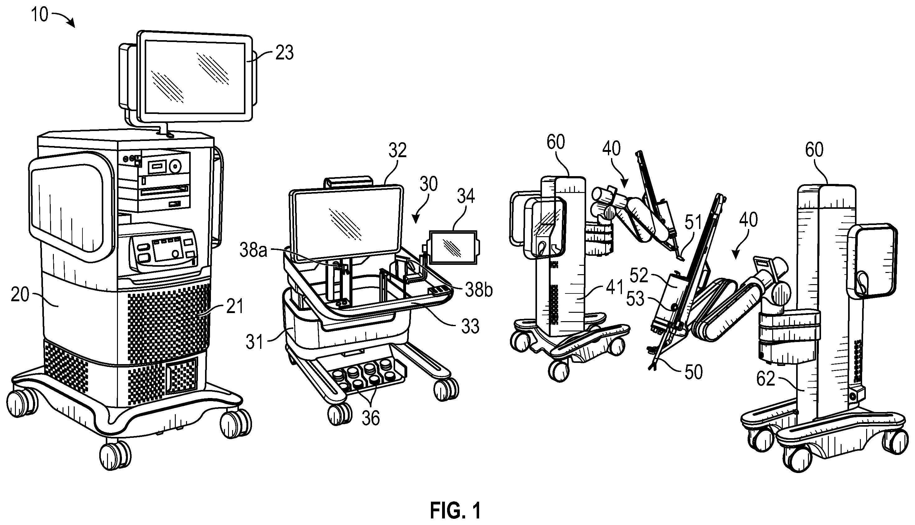
is a schematic illustration of a surgical robotic system including a control tower, a surgeon console, and one or more surgical robotic arms each disposed on a movable cart according to an aspect of the present disclosure;
is a perspective view of a surgical robotic arm of the surgical robotic system of according to an aspect of the present disclosure;
is a perspective view of a setup arm with the surgical robotic arm of the surgical robotic system of according to an aspect of the present disclosure;
is a schematic diagram of a computer architecture of the surgical robotic system of according to an aspect of the present disclosure;
is a plan schematic view of the surgical robotic system of positioned about a surgical table according to an aspect of the present disclosure;
is a schematic diagram of a power supply system of the surgical robotic system of according to an aspect of the present disclosure; and
is a plan schematic view of a surgical robotic system positioned about a surgical table according to another aspect of the present disclosure.
DETAILED DESCRIPTION
With reference to , a surgical robotic system 10 includes a control tower 20 , a surgeon console 30 , and one or more robotic arms 40 . Each of the robotic arms 40 includes a surgical instrument 50 removably coupled thereto. Each of the robotic arms 40 is also coupled to a movable cart 60 .
The surgical instrument 50 is configured for use during minimally invasive surgical procedures, for instance. In aspects, the surgical instrument 50 may be configured for open surgical procedures. In further aspects, the surgical instrument 50 may be an electrosurgical forceps configured to seal tissue by compressing tissue between jaw members and applying electrosurgical current thereto. In yet further aspects, the surgical instrument 50 may be a surgical stapler including a pair of jaws configured to grasp and clamp tissue while deploying a plurality of tissue fasteners, e.g., staples, and cutting fastened tissue. Several different types of surgical instruments 50 are usable as part of the surgical robotic system 10 .
At least one of the robotic arms 40 may include an endoscopic camera 51 configured to capture video of the surgical site. In aspects, the endoscopic camera 51 may be used in connection with a movable optical head and a passive stand, and may be used without being engaged with a robotic arm 40 . The endoscopic camera 51 may be a stereoscopic endoscope configured to capture two side-by-side (e.g., left and right) images of the surgical site to produce a video stream of the surgical scene. The endoscopic camera 51 is coupled to a video processing device 56 ( ), which may be disposed within the control tower 20 . The video processing device 56 may be any computing device as described below configured to receive the video feed from the endoscopic camera 51 , perform the image processing based on the depth estimating algorithms of the present disclosure, and output the processed video stream.
The control tower 20 includes a display 23 , which may be a touchscreen, and outputs on graphical user interfaces (GUIs). The control tower 20 also acts as an interface between the surgeon console 30 and one or more robotic arms 40 . In particular, the control tower 20 is configured to control the robotic arms 40 , such as to move the robotic arms 40 and the corresponding surgical instrument 50 , based on a set of programmable instructions and/or input commands from the surgeon console 30 , in such a way that robotic arms 40 and the surgical instrument 50 execute a desired movement sequence in response to input from foot pedals 36 and/or handle controllers 38 a and 38 b or other user commands of the surgeon console 30 .
The surgeon console 30 includes a first display 32 , which displays a video feed of the surgical site provided by camera 51 of the surgical instrument 50 disposed on the robotic arm 40 , and a second display 34 , which displays a user interface for controlling the surgical robotic system 10 . The first and/or second displays 32 and 34 may be configured as touchscreens allowing for displaying various graphical user inputs. The video processing device 56 is configured to process the video feed from the endoscopic camera 51 and to output a processed video stream on the first displays 32 of the surgeon console 30 and/or the display 23 of the control tower 20 .
The surgeon console 30 also includes a plurality of user interface devices, such as foot pedals 36 and the pair of handle controllers 38 a and 38 b which may be used by a user to remotely control robotic arms 40 , surgical instruments 50 and/or endoscopic cameras 51 . The surgeon console 30 may further include an armrest 33 used to support clinician's arms while operating the handle controllers 38 a and 38 b , for instance.
Each of the control tower 20 , the surgeon console 30 , and the robotic arm 40 includes a respective computer 21 , 31 , 41 . The computers 21 , 31 , 41 are interconnected to each other using any suitable communication network based on wired or wireless communication protocols. The term “network,” whether plural or singular, as used herein, denotes a data network, including, but not limited to, the Internet, Intranet, a wide area network, or a local area networks, and without limitation as to the full scope of the definition of communication networks as encompassed by the present disclosure. Suitable protocols include, but are not limited to, transmission control protocol/internet protocol (TCP/IP), datagram protocol/internet protocol (UDP/IP), and/or datagram congestion control protocol (DCCP). Wireless communication may be achieved via one or more wireless configurations, e.g., radio frequency, optical, Wi-Fi, Bluetooth (an open wireless protocol for exchanging data over short distances, using short length radio waves, from fixed and mobile devices, creating personal area networks (PANs), ZigBee® (a specification for a suite of high level communication protocols using small, low-power digital radios based on the IEEE 122.15.4-2003 standard for wireless personal area networks (WPANs)).
The computers 21 , 31 , 41 may include any suitable processor (not shown) operably connected to a memory (not shown), which may include one or more of volatile, non-volatile, magnetic, optical, or electrical media, such as read-only memory (ROM), random access memory (RAM), electrically-erasable programmable ROM (EEPROM), non-volatile RAM (NVRAM), or flash memory. The processor may be any suitable processor (e.g., control circuit) adapted to perform the operations, calculations, and/or set of instructions described in the present disclosure including, but not limited to, a hardware processor, a field programmable gate array (FPGA), a digital signal processor (DSP), a central processing unit (CPU), a microprocessor, and combinations thereof. Those skilled in the art will appreciate that the processor may be substituted for by using any logic processor (e.g., control circuit) adapted to execute algorithms, calculations, and/or set of instructions described herein.
With reference to , each of the robotic arms 40 may include a plurality of links 42 a , 42 b , 42 c , which are interconnected at joints 44 a , 44 b , 44 c , respectively. The joint 44 a is configured to secure the robotic arm 40 to the movable cart 60 and defines a first longitudinal axis.
With reference to , the movable cart 60 includes a lift 61 and a setup arm 62 , which provides a base for mounting of the robotic arm 40 . The lift 61 allows for vertical movement of the setup arm 62 . The movable cart 60 also includes a display 69 for displaying information pertaining to the robotic arm 40 .
The setup arm 62 includes a first link 62 a , a second link 62 b , and a third link 62 c , which provide for lateral maneuverability of the robotic arm 40 . The links 62 a , 62 b , 62 c are interconnected at joints 63 a and 63 b , each of which may include an actuator (not shown) for rotating the links 62 b and 62 b relative to each other and the link 62 c . In particular, the links 62 a , 62 b , 62 c are movable in their corresponding lateral planes that are parallel to each other, thereby allowing for extension of the robotic arm 40 relative to the patient (e.g., surgical table). In aspects, the robotic arm 40 may be coupled to a surgical table. The setup arm 62 includes controls 65 for adjusting movement of the links 62 a , 62 b , 62 c as well as the lift 61 .
The third link 62 c includes a rotatable base 64 having two degrees of freedom. In particular, the rotatable base 64 includes a first actuator 64 a and a second actuator 64 b . The first actuator 64 a is rotatable about a first stationary arm axis which is perpendicular to a plane defined by the third link 62 c and the second actuator 64 b is rotatable about a second stationary arm axis which is transverse to the first stationary arm axis. The first and second actuators 64 a and 64 b allow for full three-dimensional orientation of the robotic arm 40 .
The actuator 48 b of the joint 44 b is coupled to the joint 44 c via the belt 45 a , and the joint 44 c is in turn coupled to the joint 46 c via the belt 45 b . Joint 44 c may include a transfer case coupling the belts 45 a and 45 b , such that the actuator 48 b is configured to rotate each of the links 42 b , 42 c and the holder 46 relative to each other. More specifically, links 42 b , 42 c , and the holder 46 are passively coupled to the actuator 48 b which enforces rotation about a pivot point “P” which lies at an intersection of the first axis defined by the link 42 a and the second axis defined by the holder 46 . Thus, the actuator 48 b controls the angle θ between the first and second axes allowing for orientation of the surgical instrument 50 . Due to the interlinking of the links 42 a , 42 b , 42 c , and the holder 46 via the belts 45 a and 45 b , the angles between the links 42 a , 42 b , 42 c , and the holder 46 are also adjusted in order to achieve the desired angle θ. In aspects, some or all of the joints 44 a , 44 b , 44 c may include an actuator to obviate the need for mechanical linkages.
The joints 44 a and 44 b include an actuator 48 a and 48 b configured to drive the joints 44 a , 44 b , 44 c relative to each other through a series of belts 45 a and 45 b or other mechanical linkages such as a drive rod, a cable, or a lever and the like. In particular, the actuator 48 a is configured to rotate the robotic arm 40 about a longitudinal axis defined by the link 42 a . Each of the actuators 48 a and b and the actuators of the joints 63 a and b may also include a brake to stop rotation of the corresponding joints 44 a - c and 63 a and b.
With reference to , the robotic arm 40 also includes a holder 46 defining a second longitudinal axis and configured to receive an instrument drive unit (IDU) 52 ( ). The IDU 52 is configured to couple to an actuation mechanism of the surgical instrument 50 and/or the camera 51 , and is configured to move (e.g., rotate) and actuate the instrument 50 and/or the camera 51 . IDU 52 transfers actuation forces from its actuators to the surgical instrument 50 to actuate components (e.g., end effector) of the surgical instrument 50 . The holder 46 includes a sliding mechanism 46 a , which is configured to move the IDU 52 along the second longitudinal axis defined by the holder 46 . The holder 46 also includes a joint 46 b , which rotates the holder 46 relative to the link 42 c . During endoscopic procedures, the instrument 50 may be inserted through an endoscopic port 55 ( ) held by the holder 46 .
The robotic arm 40 may also include one or more manual override buttons 53 ( ) disposed on the IDU 52 and/or the setup arm 62 , which may be used in a manual mode. The user may press one or more of the buttons 53 to move the component associated with the button 53 .
With reference to , each of the computers 21 , 31 , 41 of the surgical robotic system 10 may include a plurality of controllers, which may be embodied in hardware and/or software. The computer 21 of the control tower 20 includes a controller 21 a and safety observer 21 b . The controller 21 a receives data from the computer 31 of the surgeon console 30 about the current position and/or orientation of the handle controllers 38 a and 38 b and the state of the foot pedals 36 and other buttons. The controller 21 a processes these input positions to determine desired drive commands for each joint of the robotic arm 40 and/or the IDU 52 and communicates these to the computer 41 of the robotic arm 40 . The controller 21 a also receives the actual joint angles measured by encoders of the actuators 48 a and 48 b and uses this information to determine force feedback commands that are transmitted back to the computer 31 of the surgeon console 30 to provide haptic feedback through the handle controllers 38 a and 38 b , for instance. The safety observer 21 b performs validity checks on the data going into and out of the controller 21 a and notifies a system fault handler if errors in the data transmission are detected to place the computer 21 and/or the surgical robotic system 10 into a safe state.
The computer 41 of the robotic arm 40 includes a plurality of controllers, namely, a main cart controller 41 a , a setup arm controller 41 b , a robotic arm controller 41 c , and an instrument drive unit (IDU) controller 41 d . The main cart controller 41 a receives and processes joint commands from the controller 21 a of the computer 21 and communicates them to the setup arm controller 41 b , the robotic arm controller 41 c , and the IDU controller 41 d . The main cart controller 41 a also manages instrument exchanges and the overall state of the movable cart 60 , the robotic arm 40 , and the IDU 52 . The main cart controller 41 a also communicates actual joint angles back to the controller 21 a.
The setup arm controller 41 b controls each of joints 63 a and 63 b , and the rotatable base 64 of the setup arm 62 and calculates desired motor movement commands (e.g., motor torque) for the pitch axis and controls the brakes. The robotic arm controller 41 c controls each joint 44 a and 44 b of the robotic arm 40 and calculates desired motor torques required for gravity compensation, friction compensation, and closed loop position control of the robotic arm 40 . The robotic arm controller 41 c calculates a movement command based on the calculated torque. The calculated motor commands are then communicated to one or more of the actuators 48 a and 48 b in the robotic arm 40 . The actual joint positions are then transmitted by the actuators 48 a and 48 b back to the robotic arm controller 41 c.
The IDU controller 41 d receives desired joint angles for the surgical instrument 50 , such as wrist and jaw angles, and computes desired currents for the motors in the IDU 52 . The IDU controller 41 d calculates actual angles based on the motor positions and transmits the actual angles back to the main cart controller 41 a.
The robotic arm 40 is controlled in response to a pose of the handle controller controlling the robotic arm 40 , e.g., the handle controller 38 a , which is transformed into a desired pose of the robotic arm 40 through a hand eye transform function executed by the controller 21 a . The hand eye function, as well as other functions described herein, is/are embodied in software executable by the controller 21 a or any other suitable controller described herein. The pose of one of the handle controller 38 a may be embodied as a coordinate position and role-pitch-yaw (“RPY”) orientation relative to a coordinate reference frame, which is fixed to the surgeon console 30 . The desired pose of the instrument 50 is relative to a fixed frame on the robotic arm 40 . The pose of the handle controller 38 a is then scaled by a scaling function executed by the controller 21 a . In aspects, the coordinate position is scaled down and the orientation is scaled up by the scaling function. In addition, the controller 21 a also executes a clutching function, which disengages the handle controller 38 a from the robotic arm 40 . In particular, the controller 21 a stops transmitting movement commands from the handle controller 38 a to the robotic arm 40 if certain movement limits or other thresholds are exceeded and in essence acts like a virtual clutch mechanism, e.g., limits mechanical input from effecting mechanical output.
The desired pose of the robotic arm 40 is based on the pose of the handle controller 38 a and is then passed by an inverse kinematics function executed by the controller 21 a . The inverse kinematics function calculates angles for the joints 44 a , 44 b , 44 c of the robotic arm 40 that achieve the scaled and adjusted pose input by the handle controller 38 a . The calculated angles are then passed to the robotic arm controller 41 c , which includes a joint axis controller having a proportional-derivative (PD) controller, the friction estimator module, the gravity compensator module, and a two-sided saturation block, which is configured to limit the commanded torque of the motors of the joints 44 a , 44 b , 44 c.
With reference to , the surgical robotic system 10 is shown set up around a surgical table 100 . The system 10 includes the control tower 20 , the surgeon console 30 , and the plurality of movable carts 60 a - d , which may be numbered “1” through “4.” Here, the control tower 20 , the surgeon console 30 , and each of the movable carts 60 a - d is positioned around the surgical table 100 . Position and orientation of the movable carts 60 a - d depends on a plurality of factors, such as placement of a plurality of ports 55 a - d , which in turn, depends on the surgery being performed. Once the port placement is determined, the ports 55 a - d are inserted into the patient, each of the robotic arms 40 a - d is aligned to achieve a desired configuration of each of their respective joints, and the movable carts 60 a - d are positioned to insert instruments 50 and the endoscopic camera 51 into corresponding the ports 55 a - d . The control tower 20 and the surgeon console 30 are positioned and orientated based on the preference of the surgeon, for example. While four movable carts 60 a - 60 d are shown, the surgical robotic system 10 may include more or fewer than four movable carts.
With continued reference to , electrical connections of each component of the surgical robotic system 10 are shown and include a daisy chain arrangement. More particularly, the surgeon console 30 is electrically coupled to the control tower 20 via a cable 72 a having a connector 74 a , the first movable cart 60 a is electrically coupled to the surgeon console 30 via a cable 72 b having a connector 74 b , the second movable cart 60 b is electrically coupled to the first movable cart 60 a via a cable 72 c having a connector 74 c , the third movable cart 60 c is electrically coupled to the second movable cart 60 b via a cable 72 d having a connector 74 d , and the fourth movable cart 60 d is electrically coupled to the third movable cart 60 c via a cable 72 e having a connector 74 e . Additionally, in aspects, the surgical table 100 is included in the daisy chain arrangement. In such an arrangement, one of the components of the surgical robotic system 10 (e.g., the fourth movable cart 60 d ) would be electrically coupled to the surgical table 100 via a cable having a connector. Further, in addition to or instead of the daisy chaining of electrical connections, at least part of the daisy chain arrangement may also be used for communication.
With reference to , the surgical robotic system 10 includes a power supply system 200 housed in the control tower 20 . The surgeon console 30 and each of the movable carts 60 a - d is electrically coupled to the power supply system 200 of the control tower 20 , directly or indirectly, via the cables 72 a - e and the respective connectors 74 a - e (only two movable carts 60 a and 60 b and their associated cables 72 a and 72 b and connectors 74 a and 74 b are shown in for simplicity). The power supply system 200 includes a power ingress module 202 coupled to an electrical main supplying alternating current and an isolation transformer 206 . The power supply system 200 also includes one or more uninterruptible power supply (“UPS”) 208 coupled to the isolation transformer 206 . The UPS 208 provides backup electrical power and is coupled to a tower power supply chassis (“TPSC”) 210 .
With continued reference to , in the illustrated aspect, the TPSC 210 includes a power supply 212 a configured to provide a regulated DC output to the surgeon console 30 via the cable 72 a and the connector 74 a . The surgeon console 30 includes a power supply 212 b configured to provide a regulated DC output to the first movable cart 60 a via the cable 72 b and the connector 74 b . The first movable cart 60 a includes a power supply 212 c configured to provide a regulated DC output to the second movable cart 60 b via the cable 72 c and the connector 74 d . The second movable cart 60 b includes a power supply 212 d configured to provide a regulated DC output to an additional movable cart. Likewise, additional movable carts (e.g., movable carts 60 c and 60 d ) also include power supplies configured to provide a regulated DC output to other movable carts via cables and connectors. Further, while a particular orientation of the components of the surgical robotic system 10 is shown, each of the surgeon console 30 and the movable carts 60 a - d are configured to be electrically coupled to any other the surgeon console 30 , the movable carts 60 a - d , and the control tower 20 . For instance, the second movable cart 60 b can be electrically coupled to the control tower 20 directly.
In this aspect, where power is supplied in a daisy chained arrangement, the overall length of power cables is minimized thereby making the operating room environment more user-friendly, easier to manage, easier to arrange, easier to setup, and safer.
Additionally, in aspects, the surgeon console 30 and/or the movable carts 60 a - d include a battery to supply power (e.g., in addition to the power supply 212 a - d ). Here, when one of batteries is low on power or has been drained of power, the associated movable cart 60 a , for instance, can be plugged into another component, such as movable cart 60 b , to utilize power therefrom.
In aspects, as well as the power supplies 212 a - d discussed above, the TPSC 210 may include a plurality of additional power supplies configured to provide a regulated DC output to each of the surgeon console 30 and the movable carts 60 a - d . Here, the user would have an option to supply power to the surgeon console 30 and the movable carts 60 a - d in the manner shown in , or to be able to plug any or all of the movable carts 60 a - d directly into the control tower 20 .
Referring to , the surgical robotic system 10 is shown set up around a surgical table 100 and includes an additional cable and connector as compared to the arrangement shown in . Here, in the embodiment illustrated in , the fourth movable cart 60 d is electrically coupled to the control tower 20 via a cable 72 f having a connector 74 f . This electrical connection between the fourth movable cart 60 d and the control tower 20 results in a closed loop system including the control tower 20 , the surgeon console 30 , and all of the movable carts 60 a - d . Such a closed loop system can provide an emergency path of communication and/or power in the event one of the cables 72 a - f in the chain becomes damaged or disconnected, for instance. Additionally, this closed loop system can be employed in surgical robotic systems having more or fewer than four movable carts without departing from the scope of the disclosure. Further details of the power supply system 200 are disclosed in International Application No. PCT/US21/14873, filed on Jan. 25, 2021, the entire contents of which are incorporated by reference herein.
It will be understood that various modifications may be made to the aspects disclosed herein. In aspects, the color-coded relative position, angular orientation, and operational status of each robotic arm may also be simultaneously viewable on multiple displays. Therefore, the above description should not be construed as limiting, but merely as exemplifications of various aspects. Those skilled in the art will envision other modifications within the scope and spirit of the claims appended thereto.
Figures (7)
Citations
This patent cites (35)
- US6527721
- US9204923
- US9680333
- US11272977
- US11357566
- US11666374
- US12262938
- US2007/0114852
- US2008/0108443
- US2010/0130986
- US2016/0346930
- US2018/0092648
- US2019/0069962
- US2019/0201040
- US2019/0201111
- US2019/0201118
- US2019/0231460
- US2019/0364651
- US2020/0138534
- US2020/0405414
- US2022/0395338
- US2022/0401178
- US2023/0320794
- US101160104
- US105573253
- US110811880
- US2533130
- US2923661
- US2017168950
- USWO-2006124390
- US2014071184
- USWO-2018053349
- US2020210106
- US2021158383
- USWO-2022115685