Sheet Identification Device and Image Processing Apparatus Capable of Identifying Fiber Direction of Sheet
Abstract
A sheet identification device includes a light irradiation portion. When forming an identification image, the light irradiation portion projects first pattern light (P 11 ) and second pattern light (P 12 ) having different dependences on a fiber direction of a surface of a sheet on an identification region (R 1 ). The identification image is an image of the identification region (R 1 ) of the surface of the sheet on which image formation or image reading is performed, which is used for identifying the fiber direction of the surface of the sheet.
Claims (15)
1 . A sheet identification device comprising: a light irradiation portion configured to, when forming an identification image which is an image of an identification region of a surface of a sheet on which image formation or image reading is performed and which is used for identification of a fiber direction of the surface of the sheet, project first pattern light and second pattern light having different dependences on the fiber direction on the identification region, wherein the first pattern light and the second pattern light have different line widths on the identification region to have different dependences on the fiber direction.
11 . A sheet identification device comprising: an acquisition portion configured to acquire an identification image which is an image of an identification region on which pattern light is projected of a surface of a sheet on which image formation or image reading is performed; and a direction identification portion configured to identify a fiber direction of the surface of the sheet, based on the identification image, wherein: the pattern light includes first pattern light and second pattern light having different dependences on the fiber direction, the direction identification portion identifies the fiber direction based on a comparison result between the first pattern light and the second pattern light in the identification image, and the first pattern light and the second pattern light have different line widths on the identification region to have different dependences on the fiber direction.
15 . A sheet identification device comprising: an acquisition portion configured to acquire an identification image which is an image of an identification region on which pattern light is projected of a surface of a sheet on which image formation or image reading is performed; and a direction identification portion configured to identify a fiber direction of the surface of the sheet, based on the identification image, wherein: the pattern light includes first pattern light and second pattern light having different dependences on the fiber direction, the direction identification portion identifies the fiber direction based on a comparison result between the first pattern light and the second pattern light in the identification image, and the direction identification portion identifies the fiber direction, based at least on a comparison result between a variation in a line width of the first pattern light and a variation in a line width of the second pattern light on the identification region.
Show 12 dependent claims
2 . The sheet identification device according to claim 1 , wherein a line width of the first pattern light on the identification region is 100 μm or more, and a line width of the second pattern light on the identification region is less than 100 μm.
3 . The sheet identification device according to claim 1 , further comprising: a condition determination portion configured to determine an image processing condition on the image formation or the image reading, based on the fiber direction.
4 . The sheet identification device according to claim 1 , wherein a first imaginary straight line connecting the light irradiation portion and a center of the identification region is inclined at a predetermined angle with respect to a second imaginary straight line extending along a conveying direction of the sheet.
5 . The sheet identification device according to claim 4 , wherein the predetermined angle is 20 degrees or more and 90 degrees or less.
6 . The sheet identification device according to claim 1 , wherein the first pattern light and the second pattern light both form a stripe pattern in which a bright portion and a dark portion are alternately arranged on the identification region.
7 . The sheet identification device according to claim 6 , wherein a direction in which the bright portion and the dark portion are arranged is identical for the first pattern light and the second pattern light.
8 . The sheet identification device according to claim 1 , wherein the identification region is divided into a first small region on which the first pattern light is projected and a second small region on which the second pattern light is projected.
9 . The sheet identification device according to claim 1 , wherein the light irradiation portion includes: a light source; and a shield configured to block part of light output from the light source to allow the first pattern light and the second pattern light to pass therethrough.
10 . An image processing apparatus comprising: the sheet identification device according to claim 1 ; and an image processing portion configured to execute at least one of the image formation and the image reading on the sheet.
12 . The sheet identification device according to claim 11 , wherein a line width of the first pattern light on the identification region is 100 μm or more, and a line width of the second pattern light on the identification region is less than 100 μm.
13 . The sheet identification device according to claim 11 , further comprising: a condition determination portion configured to determine an image processing condition on the image formation or the image reading, based on the fiber direction.
14 . The sheet identification device according to claim 11 , further comprising: an asperity identification portion configured to identify asperity information on asperities on the surface of the sheet, based on the identification image.
Full Description
Show full text →
TECHNICAL FIELD
The present invention relates to a sheet identification device, an image processing apparatus, and a sheet identification method.
BACKGROUND
As a related technique, there is known a technique used in an image forming apparatus such as a copier or a laser printer, which automatically identifies the type of a sheet (paper) from an image of the surface of the sheet (see, for example, Patent Literature 1). An image reading apparatus according to the related technique is provided with a light emitting element that obliquely irradiates the surface of the sheet with light, and an area sensor that reads the irradiation region as an image, and reads information on the sheet from the reading result.
In this image reading apparatus, the surface roughness of the sheet is estimated by detecting a shadow image caused by the asperities on the surface of the sheet from the image of the light application area. When the asperities on the surface of the sheet are large, the contrast is higher than when the asperities are small, so that the magnitude of the asperities on the surface can be estimated from the contrast. Further, this image reading apparatus is configured to set the incident direction of the light from the light emitting element at an angle of 45 degrees with respect to the conveying direction of the sheet so as to maintain the fiber direction of the sheet and the incident direction of the light at an angle of approximately 45 degrees and reduce the variation in the detection accuracy depending on the fiber direction.
CITATION LIST
Patent Literature
•
• Patent Literature 1: Japanese Unexamined Patent Application Publication No. 2004-038879
SUMMARY OF INVENTION
Technical Problem
However, it is difficult to identify the fiber direction of the sheet with the configuration of the related technique described above because the magnitude of the asperities is estimated while ignoring the influence of the fiber direction of the sheet in this configuration.
An object of the present invention is to provide a sheet identification device and an image processing apparatus which can easily identify the fiber direction of the sheet.
Solution to Problem
A sheet identification device according to an aspect of the present invention includes a light irradiation portion. When forming an identification image, the light irradiation portion projects first pattern light and second pattern light having different dependences on a fiber direction on an identification region. The identification image is an image of the identification region on a surface of a sheet on which image formation or image reading is performed, which is used for identifying the fiber direction of the surface of the sheet.
An image processing apparatus according to another aspect of the present invention includes the sheet identification device and an image processing portion. The image processing portion executes at least one of the image formation and the image reading on the sheet.
Advantageous Effects of Invention
According to the present invention, it is possible to provide a sheet identification device and an image processing apparatus which can easily identify the fiber direction of the sheet.
BRIEF DESCRIPTION OF THE DRAWINGS
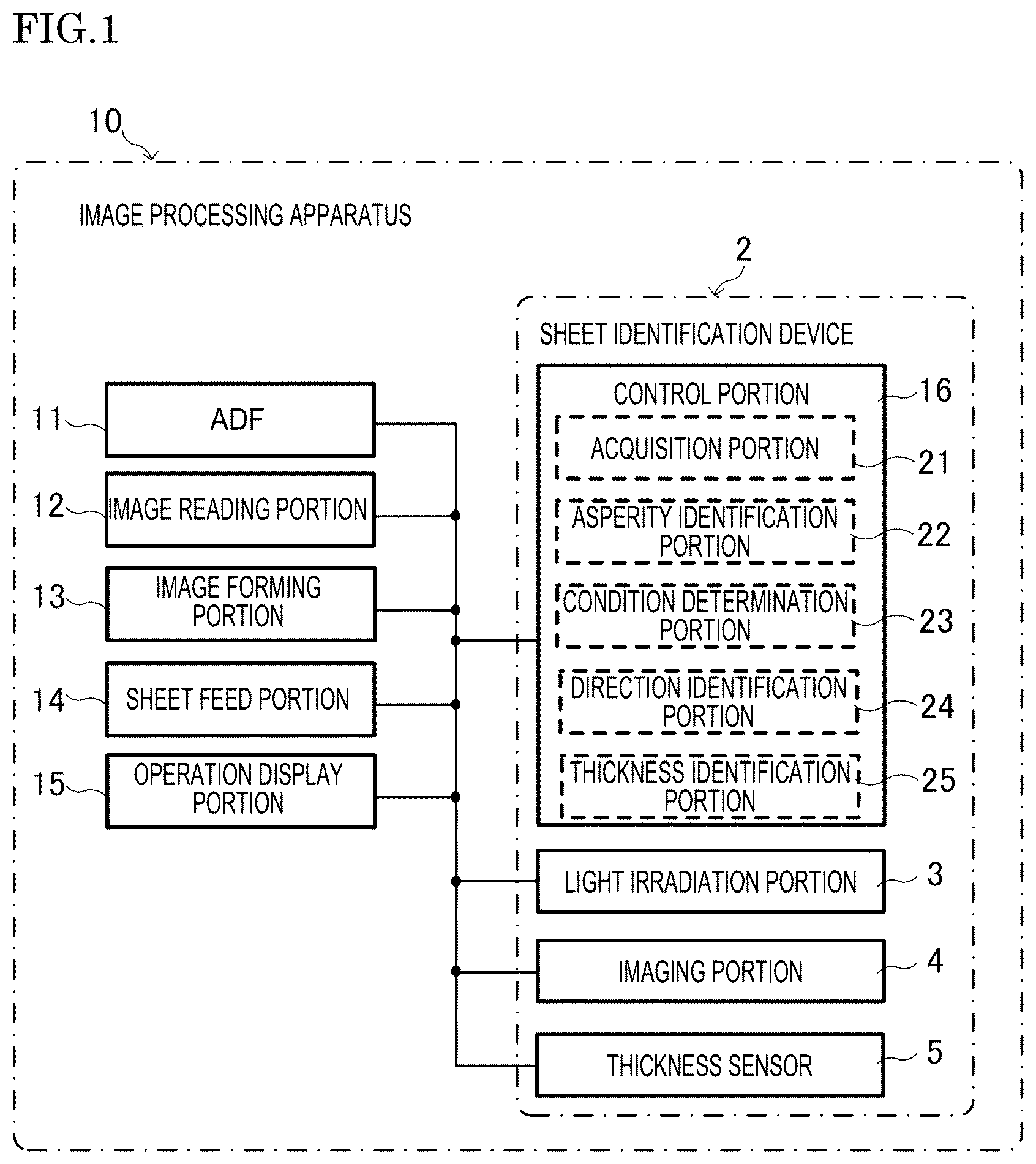
is a schematic block diagram of an image processing apparatus according to a first embodiment.
is a schematic diagram showing the exterior and internal configuration of the image processing apparatus according to the first embodiment.
is a schematic diagram showing a light irradiation portion and an imaging portion of a sheet identification device according to the first embodiment.
is a schematic diagram showing a sheet and the light irradiation portion of the sheet identification device according to the first embodiment.
is a schematic diagram showing the principle of sheet surface asperity detection in the sheet identification device according to the first embodiment.
is a diagram showing an example of an identification image obtained in the sheet identification device according to the first embodiment.
is a flowchart of an example operation of the sheet identification device according to the first embodiment.
is a diagram showing an example of the identification image when a predetermined angle obtained in the sheet identification device according to the first embodiment is changed.
is a graph showing the relationship between the arithmetic average height and the standard deviation obtained in the sheet identification device according to the first embodiment.
is a table showing the results of calculating the determination coefficient while changing the line width of pattern light and the relationship between the irradiation direction of the pattern light and the fiber direction in the sheet identification device according to the first embodiment.
is a schematic diagram showing pattern light which produces a lattice pattern in the sheet identification device according to the first embodiment.
is a schematic diagram showing one mode of pattern light used in the sheet identification device according to the first embodiment.
is a flowchart of an example operation of the sheet identification device according to the first embodiment.
is a schematic diagram showing one mode of pattern light used in the sheet identification device according to the first embodiment.
is a schematic diagram showing one mode of pattern light used in the sheet identification device according to the first embodiment.
is a schematic diagram showing one mode of pattern light used in the sheet identification device according to the first embodiment.
is a schematic diagram showing one mode of pattern light used in the sheet identification device according to the first embodiment.
is a schematic diagram showing one mode of pattern light used in the sheet identification device according to the first embodiment.
is a schematic block diagram of an image processing apparatus according to a second embodiment.
DETAILED DESCRIPTION
Embodiments of the present invention will be described below with reference to the accompanying drawings. The following embodiments are examples of embodying the present invention and do not limit the technical scope of the present invention.
First Embodiment
[1] Overall Configuration of Image Processing Apparatus
First, an overall configuration of an image processing apparatus 10 according to the present embodiment will be described with reference to and .
The image processing apparatus 10 according to the present embodiment is a multifunction peripheral having a plurality of functions such as a scanning function for reading an image (image data) from a document sheet, a printing function for forming an image based on the image data, a facsimile function, and a copy function. The image processing apparatus 10 may be a printer, a scanner, a facsimile machine, a copier, or the like as long as it has an image processing function including at least one of a function of forming an image and a function of reading an image.
As shown in , the image processing apparatus 10 includes an automatic document conveying device 11 , an image reading portion 12 , an image forming portion 13 , a sheet feed portion 14 , an operation display portion 15 , and a control portion 16 . Since the automatic document conveying device 11 is an auto document feeder (ADF), it is indicated as “ADF” in and referred to as an “ADF 11 ” in the following description. In the present embodiment, as shown in , the image processing apparatus 10 includes a housing 100 . The ADF 11 , the image reading portion 12 , the image forming portion 13 , the sheet feed portion 14 , the operation display portion 15 , and the control portion 16 are provided in the housing 100 .
The ADF 11 conveys a sheet (document sheet) whose image is read by the image reading portion 12 . The ADF 11 includes a document sheet loading portion, a plurality of conveying rollers, a document sheet holder, a sheet discharge portion, and the like.
The image reading portion 12 reads an image from a sheet and outputs image data corresponding to the read image. The image reading portion 12 includes a document sheet table, a light source, a plurality of mirrors, an optical lens, a charge coupled device (CCD), and the like.
The image forming portion 13 forms an image on a sheet Sh 1 based on the image data output from the image reading portion 12 (see ). In addition, the image forming portion 13 forms an image on a sheet Sh 1 based on image data input from an information processing apparatus, such as a personal computer, external to the image processing apparatus 10 . In the present embodiment, as an example, as shown in , the image forming portion 13 includes a transfer device 131 , a fixing device 132 , a sheet discharge tray 133 , and the like, and forms an image on a sheet Sh 1 using an electrophotographic method. The image forming portion 13 is not necessarily configured to form only monochrome images, and may be configured to form full-color images using four colors of C (cyan), M (magenta), Y (yellow), and K (black). In addition, the image forming portion 13 may form an image on a sheet using an image forming method other than the electrophotographic method, such as an inkjet method.
The image forming portion 13 forms an image on a sheet Sh 1 using toner as a developer. Specifically, the image forming portion 13 forms an electrostatic latent image on a charged surface of the photoconductor drum by irradiating the surface with a laser beam, and forms a toner image on the surface of the photoconductor drum by developing the electrostatic latent image with toner. The transfer device 131 transfers the toner image to the sheet Sh 1 conveyed through a conveying path T 1 (see ). The fixing device 132 melts and fixes the toner image transferred to the sheet Sh 1 onto the sheet Sh 1 . For example, the fixing device 132 includes a fixing roller and a pressure roller, and heats the toner image transferred to the sheet Sh 1 and presses the sheet Sh 1 , thereby fixing the toner image onto the sheet Sh 1 . The sheet Sh 1 on which the image has been formed is discharged to the sheet discharge tray 133 . When the image forming portion 13 forms an image using an inkjet method, ink (another example of the developer) is supplied instead of the toner.
The sheet feed portion 14 supplies the sheet Sh 1 to the image forming portion 13 . The sheet feed portion 14 includes a plurality of sheet feed cassettes 141 , a manual feed tray, and a plurality of conveying rollers. The sheet feed portion 14 conveys the sheet Sh 1 from the plurality of sheet feed cassettes 141 , the manual feed tray, or the like through the conveying path T 1 by the plurality of conveying rollers and the like to supply the sheet Sh 1 to the image forming portion 13 . The image forming portion 13 forms an image on the sheet Sh 1 supplied from the sheet feed portion 14 through the conveying path T 1 .
The operation display portion 15 is a user interface in the image processing apparatus 10 . The operation display portion 15 includes a display portion, such as a liquid crystal display, for displaying various types of information in response to a control instruction from the control portion 16 , and an operation portion, such as a switch or a touch panel, for inputting various types of information to the control portion 16 in response to a user's operation. In addition, the image processing apparatus 10 may include, as a user interface, an audio output portion, an audio input portion, and the like, in addition to or instead of the operation display portion 15 .
The control portion 16 comprehensively controls the image processing apparatus 10 . The control portion 16 is mainly composed of a computer system including one or more processors and one or more memories. In the image processing apparatus 10 , the functions of the control portion 16 are realized by one or more processors executing programs. The programs may be stored in advance in the one or more memories, may be provided through a telecommunications line such as the Internet, or may be provided by being stored in on a non-transitory recording medium readable by the computer system, such as a memory card or an optical disk. The one or more processors are composed of one or more electronic circuits, including a semiconductor integrated circuit. Further, the computer system in the present disclosure includes a microcontroller having one or more processors and one or more memories. The control portion 16 may be a control portion provided separately from the main control portion which comprehensively controls the image processing apparatus 10 .
In addition, the image processing apparatus 10 further includes a storage portion, a communication portion, a power supply portion, and the like. The storage portion includes one or more nonvolatile memories, and stores in advance information, such as control programs, for causing the control portion 16 to execute various types of processing. The communication portion is an interface that executes data communication between the image processing apparatus 10 and an external apparatus connected via a communication network such as the Internet or a local area network (LAN). The power supply portion is a power supply circuit that generates (outputs) electric power for the operation of the image processing apparatus 10 .
As a technique related to this type of image processing apparatus 10 , there is known a technique which is used in an image forming apparatus such as a copier or a laser printer to automatically identify the type of a sheet (paper) from an image of the surface of the sheet. An image reading apparatus according to the related technique includes a light emitting element that obliquely irradiates the surface of the sheet with light, and an area sensor that reads the irradiation region as an image, and reads information on the sheet from the read result.
In this image reading apparatus, the surface roughness of the sheet is estimated by detecting a shadow image caused by the asperities on the surface of the sheet from the image of the light application area. When the asperities on the surface of the sheet are large, the contrast is higher than when the asperities are small, so that the magnitude of the asperities on the surface can be estimated from the contrast. Further, this image reading apparatus is configured to set the incident direction of the light from the light emitting element at an angle of 45 degrees with respect to the conveying direction of the sheet so as to maintain the fiber direction of the sheet and the incident direction of the light at an angle of approximately 45 degrees and reduce the variation in the detection accuracy depending on the fiber direction.
However, with the above-described configuration of the related technique, it is necessary to make the angle of the light incident direction with respect to the surface of the sheet shallow (small) in order to obtain an image having a high sensitivity to asperities, and thus the obtained image becomes dark as a whole, and the shadow caused by the asperities is easily buried in noise.
In contrast, in the present embodiment, the image processing apparatus 10 can easily improve the accuracy of identifying the asperities on the surface of the sheet with the configuration to be described below.
That is, as shown in , the image processing apparatus 10 according to the present embodiment includes a sheet identification device 2 . The sheet identification device 2 according to the present embodiment is integrated with the image processing apparatus 10 .
The sheet identification device 2 includes an acquisition portion 21 and an asperity identification portion 22 . The acquisition portion 21 acquires an identification image Im 1 (see ). The identification image Im 1 is an image of an identification region R 1 (see ) of the surface A 1 (see ) of the sheet Sh 1 on which image formation or image reading is performed. The identification region R 1 is a region on the surface A 1 of the sheet Sh 1 on which pattern light P 1 (see ) is projected. The asperity identification portion 22 identifies asperity information on the asperities on the surface A 1 of the sheet Sh 1 based on the identification image Im 1 . In the present embodiment, the acquisition portion 21 and the asperity identification portion 22 , which are constituent elements of the sheet identification device 2 , are provided in the control portion 16 as functions of the control portion 16 .
With the above configuration, the sheet identification device 2 according to the present embodiment and the image processing apparatus 10 provided with the sheet identification device 2 have an advantage that the accuracy of identifying the asperities on the surface A 1 of the sheet Sh 1 can be easily improved. In other words, the identification region R 1 of the surface A 1 of the sheet Sh 1 is not uniformly irradiated with the light from the light emitting element, but rather the pattern light P 1 is projected thereon. Therefore, the asperity identification portion 22 can identify the asperity information on the asperities on the surface A 1 of the sheet Sh 1 from the degree of deformation or distortion of the pattern light P 1 in the identification image Im 1 . Therefore, the asperity information can be identified from a relatively bright identification image Im 1 without making the angle of the light incident direction with respect to the surface A 1 of the sheet Sh 1 shallow (small) as in the related technique, and as a result, the accuracy of identifying the asperities can be easily improved as compared with the related technique.
In addition, it is difficult to identify the fiber direction of the sheet with the configuration of the related technique described above because the magnitude of the asperities is estimated while ignoring the influence of the fiber direction of the sheet in this configuration.
In contrast, in the present embodiment, the image processing apparatus 10 can easily identify the fiber direction of the sheet with the configuration to be described below.
That is, in the present embodiment, the sheet identification device 2 includes a light irradiation portion 3 (see ). When forming the identification image Im 1 , the light irradiation portion 3 projects first pattern light P 11 (see ) and second pattern light P 12 (see ) having different dependences on the fiber direction of the surface A 1 of the sheet Sh 1 on the identification region R 1 . The identification image Im 1 is an image of the identification region R 1 of the surface A 1 of the sheet Sh 1 on which image formation or image reading is performed, which is used for identifying the fiber direction of the surface A 1 of the sheet Sh 1 . In this way, the identification region R 1 of the surface A 1 of the sheet Sh 1 is not uniformly irradiated with the light from the light emitting element, but rather the pattern light P 1 (first pattern light P 11 and second pattern light P 12 ) is projected thereon. Accordingly, use of the dependence of the pattern light P 1 on the fiber direction enables identification of the fiber direction from the identification image Im 1 . Therefore, the configuration of the present embodiment has an advantage that the fiber direction of sheet Sh 1 can be easily identified.
In the present embodiment, the sheet identification device 2 includes a direction identification portion 24 (see ) in addition to the acquisition portion 21 . The direction identification portion 24 identifies the fiber direction of the surface A 1 of the sheet Sh 1 based on the identification image Im 1 . The identification image Im 1 is an image of the identification region R 1 on which pattern light P 1 is projected of the surface A 1 of the sheet Sh 1 . In the present embodiment, the acquisition portion 21 and the direction identification portion 24 , which are constituent elements of the sheet identification device 2 , are provided in the control portion 16 as functions of the control portion 16 . In this way, the identification region R 1 of the surface A 1 of the sheet Sh 1 is not uniformly irradiated with the light from the light emitting element, but rather the pattern light P 1 is projected thereon. Accordingly, use of the dependence of the pattern light P 1 on the fiber direction enables identification of the fiber direction from the identification image Im 1 . Therefore, the configuration of the present embodiment has an advantage that the fiber direction of sheet Sh 1 can be easily identified.
The method for identifying the fiber direction will be described in detail in the section of “[8] Fiber Direction Identification Method”.
The sheet identification device 2 according to the present embodiment constitutes the image processing apparatus 10 together with the image processing portion (the image reading portion 12 and the image forming portion 13 ). In other words, the image processing apparatus 10 according to the present embodiment includes the sheet identification device 2 and an image processing portion that executes at least one of image formation and image reading on the sheet Sh 1 .
[2] Definitions
The “sheet” in the present disclosure is a sheet on which image formation or image reading is to be performed. In the present embodiment, as an example, it is assumed that the sheet Sh 1 to be irradiated with the pattern light P 1 is a sheet Sh 1 on which image formation is to be performed by the image forming portion 13 . That is, in the present embodiment, the sheet Sh 1 conveyed through the conveying path T 1 by the sheet feed portion 14 is to be irradiated with the pattern light P 1 . However, the present disclosure is not limited to this example, and the sheet to be irradiated with the pattern light P 1 may be the sheet (document sheet) on which image reading is to be performed by the image reading portion 12 , that is, the sheet conveyed by the ADF 11 . In addition, although the sheet Sh 1 is paper as an example in the present embodiment, it is not limited to paper, and may be, for example, a resin film.
The “pattern light” in the present disclosure is, for example, light that is projected from a light irradiation portion 3 (see ) onto a projection surface (here, the surface A 1 of the sheet Sh 1 ) in a controlled shape and direction, and is so-called structured light. That is, the region (identification region R 1 ) irradiated with the pattern light P 1 is not uniformly irradiated with the pattern light P 1 , but a figure, a design, a picture, a pattern, a symbol, a character, a number, or the like corresponding to the pattern light P 1 is projected thereon. Specifically, by irradiating the identification region R 1 with the pattern light P 1 , a luminance distribution of a pattern corresponding to the pattern light P 1 , such as a stripe pattern, a lattice pattern, or an arc pattern, is produced in the identification region R 1 . Further, the pattern light P 1 is not limited to a fixed pattern such as a still image, and a luminance distribution of a pattern that changes with time such as a moving image (including an animation) may be produced in the identification region R 1 .
The “identification image” in the present disclosure is, for example, an image of the identification region R 1 on which the pattern light P 1 is projected, which is captured by an imaging portion 4 . That is, the identification image Im 1 includes the pattern light P 1 projected onto the identification region R 1 , or more strictly, a luminance distribution of a pattern corresponding to the pattern light P 1 produced in the identification region R 1 by projecting the pattern light P 1 on the identification region R 1 . The identification image Im 1 may be either a monochrome image or a color image, and may be either a still image or a moving image.
The “asperity information” in the present disclosure is information on the asperities on the surface A 1 of the sheet Sh 1 , and includes information such as the height (or depth) of the asperities and/or the size of the asperities in plan view. The surface (A 1 ) of the sheet (Sh 1 ) has asperities including at least one of a concave portion and a convex portion. That is, the surface A 1 may include only a plurality of concave portions or a plurality of convex portions. Further, the surface A 1 may include a plurality of concave portions and one convex portion. In this case, as an example, the surface A 1 includes one net-like convex portion and a plurality of concave portions consisting of mesh portions surrounded by this convex portion. Similarly, as an example, the surface A 1 may include one net-like concave portion and a plurality of convex portions consisting of mesh portions surrounded by this concave portion.
The asperities (concave portions and convex portions) of the surface A 1 have extremely small sizes that cannot be individually identified with the naked eye, and the surface A 1 of one sheet Sh 1 includes a large number of asperities. That is, the asperities are microscopic compared to the entire surface A 1 , and when a person looks at the surface A 1 , the asperities make the surface A 1 look like a rough “satin finish”. Such a large number of microscopic asperities are formed, for example, by a large number of fibers constituting paper when the sheet Sh 1 is paper, or by embossing or the like when the sheet Sh 1 is a resin film. Information on such microscopic asperities includes an index representing surface roughness, such as an arithmetic average height (Sa) or an arithmetic average height of lines (Ra).
The “fiber direction” in the present disclosure is the direction of the fibers on the surface A 1 of the sheet Sh 1 , and is, for example, the extending direction of a large number of fibers constituting paper when the sheet Sh 1 is paper, i.e., the paper grain direction. Generally, the sheet Sh 1 has a “long grain” in which the fiber direction is along the long side of the sheet Sh 1 , and a “short grain” in which the fiber direction is along the short side of the sheet Sh 1 . The conveying direction D 1 (see ) of the sheet Sh 1 in the image processing apparatus 10 is a direction along the long side or the short side of the sheet Sh 1 . Therefore, basically, the fiber direction is along the conveying direction D 1 of the sheet Sh 1 or along a direction orthogonal to the conveying direction D 1 .
[3] Sheet Identification Device
Next, a configuration of the sheet identification device 2 according to the present embodiment will be described in more detail with reference to to .
In the present embodiment, the sheet identification device 2 includes an acquisition portion 21 , an asperity identification portion 22 , a condition determination portion 23 , a direction identification portion 24 , a thickness identification portion 25 , a light irradiation portion 3 , an imaging portion 4 , and a thickness sensor 5 . The acquisition portion 21 , the asperity identification portion 22 , the condition determination portion 23 , the direction identification portion 24 , and the thickness identification portion 25 are provided in the control portion 16 as functions of the control portion 16 . That is, in the present embodiment, the image processing apparatus 10 includes not only the acquisition portion 21 , the asperity identification portion 22 , but also the condition determination portion 23 , the direction identification portion 24 , and the thickness identification portion 25 , as functions of the control portion 16 .
The light irradiation portion 3 irradiates the surface A 1 of the sheet Sh 1 with the pattern light P 1 . That is, the light irradiation portion 3 generates pattern light P 1 whose shape and direction are controlled, and irradiates the surface A 1 of the sheet Sh 1 with the pattern light P 1 , thereby projecting the pattern light P 1 on the identification region R 1 of the surface A 1 of the sheet Sh 1 . With such pattern light P 1 from the light irradiation portion 3 , a figure, a design, a picture, a pattern, a symbol, a character, a number, or the like corresponding to the pattern light P 1 is projected on the identification region R 1 of the surface A 1 of the sheet Sh 1 .
In the present embodiment, as an example, the pattern light P 1 forms a stripe pattern in which a bright portion L 1 and a dark portion L 2 are alternately arranged on the identification region R 1 , as shown in . That is, the projection of the pattern light P 1 produces a luminance distribution of a stripe pattern including the bright portions L 1 and the dark portions L 2 on the identification region R 1 . Here, the bright portions L 1 are regions brighter than the dark portions L 2 , and in other words, the stripe pattern is a pattern in which a plurality of bright portions L 1 are arranged at intervals or a pattern in which a plurality of dark portions L 2 are arranged at intervals. That is, in the identification region R 1 , the pattern light P 1 is projected to form a stripe pattern in which a linear bright portion L 1 and a linear dark portion L 2 are alternately arranged in a direction orthogonal to the longitudinal directions of the linear bright portion L 1 and the linear dark portion L 2 . In the present embodiment, as an example, a linear bright portion L 1 and a linear dark portion L 2 , which are orthogonal to the conveying direction D 1 of the sheet Sh 1 , are arranged alternately in the conveying direction D 1 . In and the like, the bright portion L 1 is indicated by shading (dot hatching), and the dark portion L 2 is indicated by blackening. Thus, deformation, distortion, or the like according to the asperities on the surface A 1 is likely to appear in the stripe pattern on the identification region R 1 . However, the pattern light P 1 that produces the stripe pattern as shown in is merely an example of the pattern light P 1 , and the pattern light P 1 can be changed as appropriate.
In the present embodiment, as shown in and , the light irradiation portion 3 includes a light source 31 and a shield 32 . The shield 32 blocks part of the light output from the light source 31 to allow the pattern light P 1 to pass therethrough. The light source 31 includes a light emitting element that emits light when electric power is supplied thereto, and outputs light generated by the light emitting element toward the shield 32 . The light source 31 is controlled by a control signal from the control portion 16 , and can be switched on/off at least at the control portion 16 . The shield 32 is disposed between the light source 31 and the identification region R 1 of the surface A 1 of the sheet Sh 1 , and is a component that blocks part of the light from the light source 31 and allows the rest to pass therethrough. Thus, part of the light output from the light source 31 is blocked by the shield 32 , and the rest passes through the shield 32 , so that the light that has passed through the shield 32 becomes pattern light P 1 controlled to have a desired shape by the shield 32 . Thus, the pattern light P 1 can be realized with a relatively simple configuration.
In the present embodiment, as an example, the light source 31 has one or more light emitting elements such as a light emitting diode (LED) or an organic electroluminescence (EL), and makes the entire light emitting surface 311 (see ) in a rectangular shape in plain view to substantially uniformly emit light to perform surface emission. Further, in the present embodiment, the light source 31 outputs parallel light or light close to parallel light. Therefore, the optical axis Ax 1 of the pattern light P 1 output from the light irradiation portion 3 (see ) is a perpendicular line of the light emitting surface 311 passing through the center (center of gravity) of the light emitting surface 311 of the light source 31 . The light source 31 may have an optical component, such as a collimator lens, for converting the light from the light emitting element into parallel light. In the present embodiment, as an example, the light source 31 outputs visible light, specifically, white light. However, the light source 31 only has to output light having a wavelength to which the imaging portion 4 is sensitive, and may output light other than white light, or may output light in a wavelength range other than visible light, such as infrared light or ultraviolet light.
In the present embodiment, as an example, the shield 32 is a rectangular plate-shaped component that absorbs or reflects light from the light source 31 , and has one or more slits 321 (see ). Thus, part of the light output from the light source 31 is blocked by the shield 32 , and the rest passes through the shield 32 through the slit 321 of the shield 32 . In the present embodiment, in order to realize the pattern light P 1 that forms a stripe pattern in the identification region R 1 , the shield 32 has a plurality of linear slits 321 . Thus, in the identification region R 1 irradiated with the pattern light P 1 , the light that has passed through the slit 321 becomes the bright portion L 1 , and the shadow of the shield 32 becomes the dark portion L 2 , so that the stripe pattern is projected. However, the present disclosure is not limited to the configuration in which the light that has passed through the slit 321 becomes the bright portion L 1 as described above, and the pattern light P 1 may be realized by, for example, “interference stripes” utilizing interference of light.
Here, a first imaginary straight line connecting the light irradiation portion 3 that applies the pattern light P 1 and the center of the identification region R 1 is inclined at a predetermined angle θ 1 with respect to a second imaginary straight line extending along the conveying direction D 1 of the sheet Sh 1 . In the present embodiment, in the identification region R 1 , the surface A 1 of the sheet Sh 1 is along the conveying direction D 1 of the sheet Sh 1 , so that the angle between the first imaginary straight line and the surface A 1 of the sheet Sh 1 is the predetermined angle θ 1 . Further, since the first imaginary straight line is the optical axis Ax 1 of the pattern light P 1 , the optical axis Ax 1 of the pattern light P 1 is inclined at the predetermined angle θ 1 with respect to the surface A 1 of the sheet Sh 1 . In particular, in the present embodiment, the light irradiation portion 3 is configured to irradiate the identification region R 1 with the pattern light P 1 obliquely at the predetermined angle θ 1 from the downstream side in the conveying direction D 1 , that is, the front side in the conveying direction of the sheet Sh 1 . Thus, deformation, distortion, or the like according to the asperities on the surface A 1 is likely to appear in the pattern on the identification region R 1 .
The imaging portion 4 captures an image of the identification region R 1 of the surface A 1 of the sheet Sh 1 as the identification image Im 1 . Since the image captured by the imaging portion 4 is an image (identification image Im 1 ) of the identification region R 1 on which the pattern light P 1 is being projected, the light irradiation portion 3 irradiates the identification region R 1 with the pattern light P 1 at least at the imaging timing of the imaging portion 4 . In the present embodiment, as an example, the imaging portion 4 and the light irradiation portion 3 are synchronized with each other, and the light irradiation portion 3 applies the pattern light P 1 in accordance with the imaging timing of the imaging portion 4 . In other words, the light irradiation portion 3 does not output the pattern light P 1 during the period in which the imaging portion 4 does not perform imaging, thereby suppressing unnecessary power consumption in the light irradiation portion 3 .
In the present embodiment, as shown in , the imaging portion 4 includes an imaging element 41 and an optical component 42 . The imaging element 41 includes an area sensor or a line sensor, and outputs image data of the captured identification image Im 1 to the control portion 16 as an electric signal. In the present embodiment, as an example, the imaging portion 4 is an area sensor of a contact image sensor (CIS) system using a complementary metal oxide semiconductor (CMOS) sensor as the imaging element 41 . However, the imaging portion 4 is not limited to this example, and may be a sensor of a CCD system using a charge coupled device (CCD) as the imaging element 41 , for example.
The optical component 42 includes, for example, an imaging lens, and is disposed between the imaging element 41 and the identification region R 1 of the surface A 1 of the sheet Sh 1 . Thus, the light of the identification region R 1 enters the imaging element 41 through the optical component 42 . In the present embodiment, the imaging element 41 and the optical component 42 are arranged on a perpendicular line of the identification region R 1 passing through the center (center of gravity) of the identification region R 1 . Further, a light receiving surface 411 (see ) of the imaging element 41 is arranged parallel to the identification region R 1 . Therefore, the optical axis Ax 2 (see ) of the imaging portion 4 is a perpendicular line of the light receiving surface 411 passing through the center (center of gravity) of the light receiving surface 411 of the imaging element 41 . The optical axis Ax 2 of the imaging portion 4 is also orthogonal to the identification region R 1 , and intersects the optical axis Ax 1 of the light irradiation portion 3 (pattern light P 1 ) at the center of the identification region R 1 . The area of the identification region R 1 captured by the imaging element 41 is equal to a numerical value obtained by dividing the area of the light receiving surface 411 of the imaging element 41 by the image magnification M of the optical component 42 . In the present embodiment, the image magnification M is assumed to be “1” for simplicity of explanation. However, the image magnification M may be a value other than 1.
In the present embodiment, as an example, the imaging portion 4 is integrated with the light irradiation portion 3 to form a sensor unit 20 (see ). In other words, the sensor unit 20 includes the light irradiation portion 3 and the imaging portion 4 . The sensor unit 20 is housed in the housing 100 of the image processing apparatus 10 , and is electrically connected to at least the control portion 16 .
In the present embodiment, as shown in , the sensor unit 20 including the light irradiation portion 3 and the imaging portion 4 is arranged to face the conveying path T 1 between the sheet feed portion 14 and the image forming portion 13 . Therefore, the imaging position of the identification region R 1 is set on the conveying path T 1 between the sheet feed portion 14 and the image forming portion 13 . That is, the light irradiation portion 3 and the imaging portion 4 can capture the identification image Im 1 by irradiating the sheet Sh 1 conveyed from the sheet feed portion 14 to the image forming portion 13 with the pattern light P 1 at a position between the sheet feed portion 14 and the image forming portion 13 . More specifically, the sensor unit 20 is disposed at a position upstream of the transfer device 131 of the image forming portion 13 and downstream of the merging point of the conveying path T 1 connected to the plurality of sheet feed cassettes 141 in the conveying direction D 1 of the sheet Sh 1 . Therefore, the identification image Im 1 can be captured by one sensor unit 20 also for the sheets Sh 1 supplied to the image forming portion 13 from the plurality of sheet feed cassettes 141 , eliminating the need to provide a sensor unit 20 for each sheet feed cassette 141 .
The surface A 1 of the sheet Sh 1 including the identification region R 1 is a side where an image is formed by the image forming portion 13 in the thickness direction of the sheet Sh 1 , as an example in the present embodiment, but is not limited to this example. The identification region R 1 may be set, for example, on a side (back side) where an image is not formed by the image forming portion 13 in the thickness direction of the sheet Sh 1 . In this case, the light irradiation portion 3 and the imaging portion 4 are disposed on the back side of the sheet Sh 1 . In addition, the identification region R 1 may be set, for example, on both sides in the thickness direction of the sheet Sh 1 . In this case, two sets of the light irradiation portion 3 and the imaging portion 4 may be provided on both sides in the thickness direction of the sheet Sh 1 , or the sheet Sh 1 may be turned over so that the identification images Im 1 on both sides of the sheet Sh 1 are captured by one set of the light irradiation portion 3 and the imaging portion 4 .
The thickness sensor 5 detects a physical quantity relating to the thickness of the sheet Sh 1 . The thickness sensor 5 outputs the detected physical quantity as an electric signal to the control portion 16 . Thus, the control portion 16 can identify the thickness of the sheet Sh 1 . As an example, the thickness sensor 5 includes an optical sensor that detects the thickness (or basis weight) of the sheet Sh 1 using transmitted light. The thickness sensor 5 may be included in the sensor unit 20 or provided separately from the sensor unit 20 .
The acquisition portion 21 acquires the identification image Im 1 captured by the imaging portion 4 . Specifically, the acquisition portion 21 acquires the image data of the identification image Im 1 captured by the imaging portion 4 as an electric signal from the imaging element 41 of the imaging portion 4 . The acquisition portion 21 controls the light irradiation portion 3 and the imaging portion 4 to cause the light irradiation portion 3 to apply the pattern light P 1 and the imaging portion 4 to capture the identification image Im 1 in accordance with, for example, the timing when the sheet Sh 1 passes a position on the conveying path T 1 corresponding to the sensor unit 20 . The identification image Im 1 acquired by the acquisition portion 21 is temporarily stored in the one or more memories. The acquisition portion 21 may acquire the identification image Im 1 from a source other than the imaging portion 4 .
The asperity identification portion 22 identifies asperity information on the asperities on the surface A 1 of the sheet Sh 1 based on the identification image Im 1 acquired by the acquisition portion 21 . Thus, the state of the asperities on the surface A 1 of the sheet Sh 1 can be identified. The asperity information includes information on at least one of the dimension of the asperities on the surface A 1 in the direction orthogonal to the plane along the surface A 1 and the dimension in the direction along the plane. That is, the asperity information includes information on the height (or depth) of the asperities, which is the dimension in the direction orthogonal to the plane along the surface A 1 and/or the size of the asperities in plan view, which is the dimension in the direction along the plane. Thus, the height (or depth) of the asperities of the surface A 1 of the sheet Sh 1 and/or the size of the asperities in plan view can be identified. In the present embodiment, as an example, the asperity identification portion 22 calculates a numerical value corresponding to the arithmetic average height (Sa) of the surface A 1 relating to the heights (or depths) of the asperities as the asperity information.
Here, the asperity identification portion 22 identifies the asperity information based on the degree of deformation, distortion, or the like of the pattern light P 1 in the identification image Im 1 . That is, since the identification image Im 1 includes a luminance distribution of a pattern (stripe pattern in the present embodiment) corresponding to the pattern light P 1 , which is produced in the identification region R 1 by the projection of the pattern light P 1 , the pattern is deformed or distorted by the asperities on the surface A 1 . For example, even when the pattern light P 1 forms a linear pattern, the pattern light P 1 projected on the surface A 1 is deformed (meandered) in accordance with the asperities on the surface A 1 . Therefore, the asperity identification portion 22 calculates asperity information on the asperities on the surface A 1 from the degree of deformation, distortion, or the like of the pattern light P 1 . In the present embodiment, the asperity identification portion 22 identifies the asperity information based at least on the variation in the line width of the pattern light P 1 on the identification region R 1 . Thus, the state of the asperities on the surface A 1 of the sheet Sh 1 can be identified by relatively simple arithmetic processing.
The condition determination portion 23 determines image processing conditions based on the asperity information identified by the asperity identification portion 22 . The image processing conditions here are conditions relating to image formation or image reading. That is, various image processing conditions including an image forming condition relating to image formation and/or an image reading condition relating to image reading executed in the image processing apparatus 10 are determined by the condition determination portion 23 . Specifically, the image processing conditions include, for example, the fixing pressure, the fixing temperature, the conveying speed of the sheet Sh 1 , the transfer voltage, or the like in the image forming portion 13 , as well as the sheet conveying speed, the light intensity, the resolution, or the like in the image reading portion 12 . For example, when the arithmetic average height (Sa) of the surface A 1 of the sheet Sh 1 is larger (i.e., rougher), heat may be more difficult to be transferred at the time of fixing by the image forming portion 13 , or the electrical contact resistance may be higher at the time of transferring, so that the current may be more difficult to flow. Therefore, the condition determination portion 23 automatically sets the image processing conditions based on the asperity information so as to increase the fixing temperature, decrease the conveying speed, or increase the transfer voltage when the arithmetic average height (Sa) becomes larger (i.e., rougher). This enables image formation and/or image reading under appropriate image processing conditions according to the asperities on the surface A 1 of the sheet Sh 1 , leading to an improvement in the quality (including image quality) of image formation and/or image reading.
In addition, in the present embodiment, the condition determination portion 23 determines image processing conditions relating to image formation or image reading based on the fiber direction. That is, in the present embodiment, the fiber direction of the surface A 1 of the sheet Sh 1 is identified by the direction identification portion 24 . Therefore, the condition determination portion 23 determines the image processing conditions based on not only the asperity information but also the fiber direction. For example, in the inkjet type image forming portion 13 , the curl behavior differs depending on the fiber direction, so that the curl direction may be predicted in accordance with the fiber direction for curl correction. The image processing conditions determined by the condition determination portion 23 based on the fiber direction include a condition for curl correction. In addition, the “skew” in which the long side or the short side of the sheet Sh 1 is tilted with respect to the conveying direction can also be estimated from the fiber direction; therefore, the image processing conditions determined by the condition determination portion 23 based on the fiber direction may include a condition for skew correction. This enables image formation and/or image reading under appropriate image processing conditions according to the fiber direction on the surface A 1 of the sheet Sh 1 , leading to an improvement in the quality (including image quality) of image formation and/or image reading.
However, the condition determination portion 23 only has to have a function of determining the image processing conditions based on at least one of the asperity information and the fiber direction. That is, the condition determination portion 23 is not necessarily be configured to determine the image processing conditions based on both the asperity information and the fiber direction, and may determine the image processing conditions based on only one of the asperity information and the fiber direction. Further, in the present embodiment, the thickness identification portion 25 identifies the thickness of the sheet Sh 1 . Therefore, the condition determination portion 23 may determine the image processing conditions based on the thickness of the sheet Sh 1 in addition to or instead of at least one of the asperity information and the fiber direction.
The direction identification portion 24 identifies the fiber direction of the surface A 1 of the sheet Sh 1 based on the identification image Im 1 . Here, the direction identification portion 24 identifies the fiber direction based on the deformation, distortion, or the like of the pattern light P 1 in the identification image Im 1 . That is, depending on the line width of the pattern light P 1 on the identification region R 1 , the degree of deformation, distortion, or the like of the pattern light P 1 caused by the asperities on the surface A 1 varies in accordance with the relationship between the extending direction of the pattern light P 1 and the fiber direction. Therefore, in the present embodiment, the direction identification portion 24 identifies the fiber direction based at least on the variation in the line width of the pattern light P 1 on the identification region R 1 . Thus, the fiber direction of the surface A 1 of the sheet Sh 1 can be identified by relatively simple arithmetic processing.
The thickness identification portion 25 identifies the thickness of the sheet Sh 1 based on the output of the thickness sensor 5 . That is, the thickness identification portion 25 receives an electric signal representing a physical quantity relating to the thickness of the sheet Sh 1 from the thickness sensor 5 , and calculates the thickness of the sheet Sh 1 . Since the sheet identification device 2 according to the present embodiment includes the thickness identification portion 25 , it can estimate the type (paper type) of the sheet Sh 1 based on not only the state of the surface A 1 of the sheet Sh 1 but also the thickness thereof.
[4] Sheet Identification Method
Next, a sheet identification method according to the present embodiment, i.e., the operation of the sheet identification device 2 will be described with reference to to .
[4.1] Principle
First, the principle of the asperity identification portion 22 identifying the asperity information based on the identification image Im 1 will be described with reference to and . In , the bright portions L 1 of the pattern light P 1 are schematically indicated by dotted lines, and the dark portions L 2 are schematically indicated by dash-dot-dot-dash lines.
As shown as “CONVEX PORTION 1 ” in the upper part of , it is assumed that there is a rectangular parallelepiped convex portion A 11 having a height ΔZ from the surface A 1 on the surface A 1 of the sheet Sh 1 . Here, the pattern light P 1 is obliquely incident on the surface A 1 of the sheet Sh 1 at the predetermined angle θ 1 . Therefore, the pattern light P 1 is projected on the same plane as the surface A 1 except at the convex portion A 11 , and projected frontward by the height ΔZ at the convex portion A 11 than on the surface A 1 , so that the projection position of the pattern light P 1 is shifted only at the convex portion A 11 when viewed from the perpendicular direction of the surface A 1 . That is, the pattern light P 1 (the bright portions L 1 and the dark portions L 2 ) of a portion provided with the convex portion A 11 in the identification image Im 1 captured by the imaging portion 4 is shifted from the original projection position on the surface A 1 by the shift amount ΔX represented by the following Equation 1: Δ X=ΔZ /tan θ1 (Equation 1)
Since the predetermined angle θ 1 is known, when the shift amount ΔX is obtained from the identification image Im 1 , the height ΔZ of the convex portion A 11 can be calculated from the shift amount ΔX and the Equation 1. Then, the asperity information of the entire identification region R 1 can be obtained from the shift amounts ΔX of the entire identification region R 1 . The asperity information calculated in this way has a correlation with the arithmetic average height (Sa) of the surface A 1 .
In addition, as shown as “CONVEX PORTION 2 ” in the lower part of , even when where is a triangular prism-shaped convex portion A 12 whose height ΔZ from the surface A 1 varies from part to part on the surface A 1 of the sheet Sh 1 , the heights AZ of the respective parts of the convex portion A 12 can be calculated. That is, similarly to the above example, by obtaining the shift amounts ΔX from the identification image Im 1 , the heights AZ of the convex portion A 12 can be calculated from the above Equation 1. Therefore, for example, as in the case of the paper sheet Sh 1 , the asperity information can also be calculated for the asperities caused by the undulation component generated by continuous entanglement of many fibers.
By the way, in the method for obtaining the roughness of the surface A 1 from the shadow image caused by the asperities as in the above-described related technique, for example, in the case of the paper sheet Sh 1 , the local fiber asperities are strongly reflected in the calculation result, so that the calculation result does not necessarily have a linear relationship with the arithmetic average height (Sa). Therefore, in the above-described method of the related technique, it is difficult to determine from the calculation result the magnitude of the surface roughness of the sheet Sh 1 of the same type (for example, plain paper), although it may be possible to discriminate between glossy paper with a high flatness (gloss paper) and plain paper, for example. Therefore, in the above-described method of the related technique, in order to determine the magnitude of the surface roughness, it is necessary to prepare in advance, for example, a table (database) in which the calculation results of various sheets Sh 1 are associated with arithmetic average heights (Sa).
In contrast, in the sheet identification device 2 according to the present embodiment, by optimizing the line width, the predetermined angle θ 1 , and the like of the pattern light P 1 , the asperity information having a high linearity with the arithmetic average height (Sa) can be calculated while also reducing the influence of local fibers. Therefore, according to the method of the present embodiment, it is possible to uniquely obtain an arithmetic average height (Sa) from the calculation result of the asperity identification portion 22 without preparing in advance the table (database) in which the calculation results (asperity information) are associated with arithmetic average heights (Sa).
shows an example of the identification image Im 1 obtained by the sheet identification device 2 according to the present embodiment. Here, as the imaging conditions of the identification image Im 1 , lit is assumed that the predetermined angle θ 1 is 40 degrees, the resolution (number of pixels) of the imaging element 41 is 100×100, the line width W 1 (see ) of the bright portion L 1 of the stripe pattern produced by the pattern light P 1 is 120 μm, and the line width W 2 (see ) of the dark portion L 2 is 120 μm. Further, it is assumed that the image magnification M is “1”, and the irradiation direction of the pattern light P 1 , that is, the arrangement direction of the bright portions L 1 and the dark portions L 2 is the same as the fiber direction.
The identification image Im 1 is composed of a plurality of pixels, and each of the plurality of pixels has a pixel value corresponding to luminance. In the present embodiment, as an example, the relationship between the luminance and the pixel value is defined such that the higher the luminance, the larger the pixel value. Therefore, in the identification image Im 1 obtained by capturing the identification region R 1 on which the pattern light P 1 is projected, the pixel values of the pixels corresponding to the bright portion L 1 are relatively large values, and the pixel values of the pixels corresponding to the dark portion L 2 are relatively small values.
The upper part (“Sa: SMALL”) of shows a identification image Im 1 when the pattern light P 1 is projected on an identification region R 1 of glossy paper (gloss paper) having a small arithmetic average height (Sa), that is, having a high flatness. On the other hand, the lower part (“Sa: LARGE”) of shows an identification image Im 1 when the pattern light P 1 is projected on an identification region R 1 of plain paper (Sa=6 μm) having a large arithmetic average height (Sa), that is, having a low flatness. As shown in , as the arithmetic average height (Sa) increases, the deformation and distortion of the stripe pattern produced by the pattern light P 1 in the identification image Im 1 increase. Specifically, when the deformation and distortion of the stripe pattern increase, the boundary line between the bright portion L 1 and the dark portion L 2 of the stripe pattern is distorted, and the variation in the line width of each of the bright portion L 1 and the dark portion L 2 increases. That is, as the arithmetic average height (Sa) increases, the undulation component of the height of the surface A 1 increases, so that the variation in the line width of each of the bright portion L 1 and the dark portion L 2 increases. As described above, in , it is apparent that, deformation, distortion, or the like occurs in the stripe pattern produced by the pattern light P 1 in the identification image Im 1 , in accordance with the asperities on the surface A 1 .
[4.2] Specific Processing
Next, specific processing for identifying the asperity information based on the identification image Im 1 by the asperity identification portion 22 will be described with reference to . Steps S 1 , S 2 , . . . in the flowchart shown in represent the numbers of the processing procedure (steps) executed by the control portion 16 . The processing to be described below is started in accordance with the timing at which the sheet Sh 1 passes the position (monitor position) corresponding to the sensor unit 20 of the conveying path T 1 , for example.
When the purpose is to restore a three-dimensional shape, the analysis of the identification image Im 1 including the pattern light P 1 can be realized by, for example, a method of continuously projecting a plurality of pattern lights P 1 and using a Fourier transform or the like of the identification images Im 1 to calculate a phase change of the pattern light P 1 . However, this method has a relatively high calculation load, takes a relatively long time to calculate the roughness (asperity information) of the surface A 1 , and also requires relatively high hardware (CPU, GPU, memory, etc.) costs. Therefore, in the present embodiment, instead of the above-described method, the following method is adopted so that the roughness (asperity information) of the surface A 1 can be calculated by relatively simple arithmetic processing.
That is, in the present embodiment, the asperity identification portion 22 calculates the width (line width) of at least one of the bright portions L 1 and the dark portions L 2 for each row (each line) of the identification image Im 1 , with the arrangement direction (left-right direction in ) of the bright portions L 1 and the dark portions L 2 in the identification image Im 1 as a “row direction”. That is, the identification image Im 1 is an “N pixels×M rows” image in which N pixels are arranged in the arrangement direction of the bright portions L 1 and the dark portions L 2 , and the asperity identification portion 22 calculates the line width of each row of the M rows included in the identification image Im 1 . The asperity identification portion 22 obtains the line width of at least one of the bright portion L 1 and the dark portion L 2 calculated for each row as described above for the entire identification image Im 1 , and calculates the magnitude of the variation in the line width in the identification image Im 1 as the asperity information. Thus, the asperity identification portion 22 can obtain asperity information having a correlation with the arithmetic average height (Sa) of the surface A 1 , based on the variation in the line width of the pattern light P 1 .
<Step S 1 >
Specifically, in step S 1 , the control portion 16 determines whether the sheet Sh 1 has reached the monitor position, that is, the position corresponding to the sensor unit 20 on the conveying path T 1 . When the sheet feed portion 14 supplies the sheet Sh 1 to the image forming portion 13 , the control portion 16 determines that the sheet Sh 1 has reached the monitor position when the sheet Sh 1 is detected by a sensor at the monitor position (S 1 : Yes), and shifts the processing to step S 2 . On the other hand, if the sheet Sh 1 is not detected by the sensor at the monitor position, the control portion 16 determines that the sheet Sh 1 has not reached the monitor position (S 1 : No), and shifts the processing to step S 1 .
<Steps S 2 and S 3 >
In step S 2 , the control portion 16 controls, at the acquisition portion 21 , the light irradiation portion 3 to cause the light irradiation portion 3 to apply the pattern light P 1 . Thus, the pattern light P 1 is projected on the identification region R 1 of the surface A 1 of the sheet Sh 1 . In step S 3 , the control portion 16 controls, at the acquisition portion 21 , the imaging portion 4 to cause the imaging portion 4 to image the identification region R 1 on which the pattern light P 1 is being projected. Thus, an identification image Im 1 , which is an image of the identification region R 1 of the surface A 1 of the sheet Sh 1 , is generated by the imaging portion 4 .
<Step S 4 >
In step S 4 , the control portion 16 acquires, at the acquisition portion 21 , an image of one row (one line) of the identification image Im 1 from the imaging portion 4 . That is, the acquisition portion 21 acquires one row of the identification image Im 1 corresponding to one pixel in the column direction. Since the imaging portion 4 (imaging element 41 ) is generally designed to sequentially read out an image for each row, the amount of memory used can be kept low by acquiring and analyzing (steps S 5 and S 6 ) the identification image Im 1 for each row in this manner.
<Step S 5 >
In step S 5 , the control portion 16 executes, at the acquisition portion 21 , preprocessing on the identification image Im 1 . At this time, one row (one line) of the identification image Im 1 acquired in step S 4 is subjected to the preprocessing. That is, the control portion 16 executes the preprocessing on the identification image Im 1 row by row. The preprocessing includes, for example, filtering processing and binarization processing. Specifically, the control portion 16 performs noise removal or the like in the filtering processing and further performs binarization with a reference value for one row of the identification image Im 1 .
The reference value used in the binarization processing is, for example, an average value of a plurality of pixels, a value determined in advance (predetermined value), or the like. The pixels corresponding to the bright portions L 1 become “white pixels” as pixels having pixel values equal to or greater than the reference value, and the pixels corresponding to the dark portions L 2 become “black pixels” as pixels having pixel values less than the reference value. The preprocessing may include trimming processing for cutting out only a part of the identification image Im 1 to narrow down the area to be processed in step S 6 . In addition, the filtering processing and the like are not essential, and may be omitted as appropriate.
<Step S 6 >
In step S 6 , the control portion 16 extracts, at the asperity identification portion 22 , width data indicating the width (line width) of at least one of the bright portion L 1 and the dark portion L 2 from the identification image Im 1 . At this time, the width data is extracted from one row (one line) of the identification image Im 1 acquired in step S 4 . That is, the control portion 16 executes extraction of width data on the identification image Im 1 row by row. Specifically, the control portion 16 calculates, as the width data, the number of white pixels corresponding to the bright portions L 1 and the number of black pixels corresponding to the dark portions L 2 in one row of the identification image Im 1 . At this time, the control portion 16 extracts the number of white pixels and the number of black pixels throughout one row of the identification image Im 1 , thereby extracting the sum of the line widths of the plurality of bright portions L 1 and the sum of the line widths of the plurality of dark portions L 2 .
In the present embodiment, as an example, both the number of white pixels corresponding to the line widths of the bright portions L 1 and the number of black pixels corresponding to the line widths of the dark portions L 2 are used as the width data, but the present disclosure is not limited to this example, and only the number of pixels of either the bright portions L 1 or the dark portions L 2 may be used as the width data. That is, the control portion 16 may identify the asperity information by focusing on the line widths of either the bright portions L 1 or the dark portions L 2 . In addition, the control portion 16 may extract the line width of each bright portion L 1 and that of each dark portion L 2 by extracting the number of white pixels consecutive in the row direction and the number of black pixels consecutive in the row direction. In this case, the control portion 16 may use the line width of each of the plurality of bright portions L 1 (or dark portions L 2 ) as the width data, or may use a representative value (for example, an average value, a mode value, a median value, or the like) of the line widths of the plurality of bright portions L 1 (or dark portions L 2 ) as the width data.
<Step S 7 >
In step S 7 , the control portion 16 determines whether or not processing has been completed to the last one row of the identification image Im 1 . That is, with respect to the “N pixels×M rows” identification image Im 1 , if the processing target is the M-th row which is the last row, the control portion 16 determines that the processing has been completed to the last row (S 7 : Yes), and shifts the processing to step S 8 . On the other hand, if the processing target is not the M-th row which is the last row, the control portion 16 determines that the processing has not been completed to the last row (S 7 : No), and shifts the processing to step S 4 to acquire the next one row of the identification image Im 1 .
<Step S 8 >
In step S 8 , the control portion 16 calculates, at the asperity identification portion 22 , the standard deviation a of the width data of the M rows of the identification image Im 1 . As the arithmetic average height (Sa) increases, the undulation component of the height of the surface A 1 increases, so that the variation in the line width of each of the bright portion L 1 and the dark portion L 2 increases (see ), and the standard deviation a increases. That is, the asperity identification portion 22 calculates the standard deviation a as the asperity information.
<Step S 9 >
In step S 9 , the control portion 16 determines, at the condition determination portion 23 , image processing conditions. That is, the condition determination portion 23 determines the image processing conditions including image forming conditions in accordance with the standard deviation a calculated in step S 8 . As an example, when the standard deviation σ increases, the condition determination portion 23 sets the image forming conditions so as to increase the fixing temperature, decrease the conveying speed, or increase the transfer voltage. Thus, when an image is formed on the sheet Sh 1 by the image forming portion 13 , the image forming conditions corresponding to the asperities on the surface A 1 of the sheet Sh 1 are automatically applied.
The procedure of the sheet identification method described above is merely an example, and the order of the processes shown in the flowchart of may be changed as appropriate.
[5] Irradiation Angle
Next, the irradiation angle of the pattern light P 1 will be described with reference to , which shows examples of the identification image Im 1 when the predetermined angle θ 1 is changed. In , as the imaging conditions of the identification image Im 1 , it is assumed that the arithmetic average height (Sa) of the identification region R 1 is 6 μm, the resolution (number of pixels) of the imaging element 41 is 100×100, the line width W 1 of the bright portion L 1 of the stripe pattern produced by the pattern light P 1 is 100 μm, and the line width W 2 of the dark portion L 2 is 100 μm. Further, it is assumed that the irradiation direction of the pattern light P 1 , that is, the arrangement direction of the bright portion L 1 and the dark portion L 2 is the same as the fiber direction.
The optical axis Ax 1 of the pattern light P 1 is inclined at the predetermined angle θ 1 with respect to the surface A 1 of the sheet Sh 1 (see ). Here, the predetermined angle θ 1 has a great influence on the brightness of the identification image Im 1 . In the method for obtaining the roughness of the surface A 1 from the shadow image caused by the asperities as in the related technique described above, the irradiation angle (corresponding to the predetermined angle θ 1 ) of the light with respect to the surface A 1 of the sheet Sh 1 is set relatively shallow (small) in order to capture the asperities on the order of several micrometers as a shadow image. In particular, in order to increase the sensitivity to asperities, the irradiation angle is set at a very shallow angle of about 10 degrees. However, at very small irradiation angles, sufficient light does not reach the imaging portion 4 , and the identification image Im 1 becomes a relatively dark image, so that a relatively expensive high-sensitivity imaging element 41 is required to obtain the roughness of the surface A 1 from the dark image.
In contrast, in the sheet identification device 2 according to the present embodiment, the roughness of the surface A 1 is obtained from the degree of deformation, distortion, or the like of the pattern light P 1 in the identification image Im 1 ; therefore, it is sufficient that deformation, distortion, or the like of the pattern light P 1 is caused by asperities. Therefore, in the present embodiment, the predetermined angle 81 can be set larger than in the method of the related technique described above, and a bright image can be realized as the identification image Im 1 . Therefore, the roughness of the surface A 1 can be obtained from the identification image Im 1 even with a relatively inexpensive imaging element 41 .
Rather, in the configuration of the present embodiment, as shown in , when the predetermined angle 81 becomes small, the shape of the pattern light P 1 projected on the identification region R 1 collapses, and the boundary between the bright portion L 1 and the dark portion L 2 of the stripe pattern becomes ambiguous. That is, as is clear from , the shape of the pattern light P 1 collapses more when the predetermined angle 81 is 30 degrees than when it is 40 degrees, when the predetermined angle 81 becomes 20 degrees, the shape of the pattern light P 1 collapses further, and when the predetermined angle 81 becomes 10 degrees, the shape of the pattern light P 1 collapses even further. From the identification image Im 1 of the pattern light P 1 whose shape has been collapsed as described above, it is difficult to extract deformation, distortion, or the like of the pattern light P 1 caused by asperities. The inventors have verified various predetermined angles 81 , and have found that the predetermined angle 81 is preferably 20 degrees or more when the sheet Sh 1 having an arithmetic average height (Sa) of the surface A 1 of about several micrometers is the target.
In short, in consideration of the brightness of the identification image Im 1 , the predetermined angle θ 1 is preferably 10 degrees or more, and more preferably 15 degrees or more. Further, in the present embodiment, the predetermined angle θ 1 is set at 20 degrees or more so that the shape of the pattern light P 1 is not too deformed. That is, the predetermined angle θ 1 is 20 degrees or more and 90 degrees or less. Here, the lower limit value of the predetermined angle θ 1 is not limited to 20 degrees, and may be, for example, 25 degrees, 30 degrees, 35 degrees, 40 degrees, 45 degrees, 50 degrees, 55 degrees, 60 degrees, 65 degrees, 70 degrees, 75 degrees, or 80 degrees. Also, the upper limit value of the predetermined angle θ 1 is not limited to 90 degrees, and may be, for example, 85 degrees, 80 degrees, 75 degrees, 70 degrees, 65 degrees, 60 degrees, 55 degrees, 50 degrees, or 45 degrees.
Since the difference between 90 degrees and the predetermined angle θ 1 corresponds to the “incident angle” which is the angle between the pattern light P 1 and the perpendicular line of the surface A 1 , the “incident angle” of the pattern light P 1 when the predetermined angle θ 1 is 20 degrees is 70 degrees (=90 degrees−20 degrees). On the other hand, when the predetermined angle is 90 degrees, the incident angle of the pattern light P 1 is 0 degrees.
[6] Line Width
Next, the line width of the pattern light P 1 will be described later with reference to and . is a graph showing the relationship between the standard deviation a as the asperity information calculated in accordance with the flowchart of and the actual arithmetic average height Sa for 48 types of sheets Sh 1 . In , the horizontal axis represents the arithmetic average height Sa, and the vertical axis represents the standard deviation a (the standard deviation a is an average value of five locations in the bright portion L 1 or the dark portion L 2 ). In , as the imaging conditions of the identification image Im 1 , it is assumed that the resolution (number of pixels) of the imaging element 41 is 100×100, the line width W 1 of the bright portion L 1 of the stripe pattern produced by the pattern light P 1 is 80 μm, and the line width W 2 of the dark portion L 2 is 80 μm. Further, it is assumed that the irradiation direction of the pattern light P 1 , that is, the arrangement direction of the bright portion L 1 and the dark portion L 2 is the same as the fiber direction.
In the example of , the determination coefficient R 2 of the linear regression model of the arithmetic average height Sa and the standard deviation a is “0.9684”, which confirms a high linearity between the standard deviation a as the asperity information and the arithmetic average height Sa.
On the other hand, shows the results of calculating the determination coefficient R 2 while changing the line width of the pattern light P 1 and the relationship between the irradiation direction of the pattern light P 1 and the fiber direction. In , as the imaging conditions of the identification image Im 1 , it is assumed that the predetermined angle 81 is 40 degrees and the resolution (number of pixels) of the imaging element 41 is 100×100. Under the conditions, the line width W 1 of the bright portion L 1 and the line width W 2 of the dark portion L 2 of the stripe pattern produced by the pattern light P 1 are changed in the range of 40 μm to 200 μm, and the relationship between the irradiation direction of the pattern light P 1 and the fiber direction is changed between “the same” (that is, parallel) and “90°” (that is, orthogonal).
According to , it is presumed that the influence of the relationship between the irradiation direction of the pattern light P 1 and the fiber direction on the standard deviation a as the asperity information varies depending on the line width of the pattern light P 1 . That is, in , it can be confirmed that the smaller (thinner) the line width of the pattern light P 1 , the greater the influence of the relationship between the irradiation direction of the pattern light P 1 and the fiber direction on the standard deviation a as the asperity information. It is considered that this is because the width of the fiber of the sheet Sh 1 is several tens of micrometers or less, and the line width of the pattern light P 1 approaches the fiber width, which makes the local undulation component of the height of the surface A 1 likely to occur as the variation in the line width of each of the bright portion L 1 and the dark portion L 2 .
When the line width of the pattern light P 1 is 100 μm or more, the determination coefficient R 2 is “0.85” or more regardless of the relationship between the irradiation direction of the pattern light P 1 and the fiber direction. Therefore, when the line width of the pattern light P 1 is 100 μm or more, the influence of the relationship between the irradiation direction of the pattern light P 1 and the fiber direction on the standard deviation a as the asperity information is relatively small, and the relationship between the irradiation direction of the pattern light P 1 and the fiber direction is negligible. In short, whether the relationship between the irradiation direction of the pattern light P 1 and the fiber direction affects the asperity information is determined depending on whether the line width W 1 of the bright portion L 1 and the line width W 2 of the dark portion L 2 of the stripe pattern produced by the pattern light P 1 are 100 μm or more, or less than 100 μm. Namely, when the line width is 100 μm or more, the relationship between the irradiation direction and the fiber direction hardly affects the asperity information, so that the calculated asperity information can be regarded as “independent of the fiber direction”. On the other hand, when the line width is less than 100 μm, the relationship between the irradiation direction and the fiber direction is likely to affect the asperity information, so that the calculated asperity information can be regarded as “dependent on the fiber direction”.
As described above, even in the sheet identification device 2 according to the present embodiment, the relationship between the irradiation direction of the pattern light P 1 and the fiber direction may affect the standard deviation a as the asperity information, depending on the line width of the pattern light P 1 . By making the line width of the pattern light P 1 relatively larger than the width of the fiber of the sheet Sh 1 , the influence can be reduced, which causes a high linearity between the standard deviation a as the asperity information and the arithmetic average height Sa.
From the above, in the present embodiment, the width of at least one of the bright portion L 1 and the dark portion L 2 is preferably 60 μm or more and 500 μm or less. Furthermore, in order to make the asperity information less susceptible to the relationship between the irradiation direction of the pattern light P 1 and the fiber direction, it is preferable that at least one of the line width W 1 of the bright portion L 1 and the line width W 2 of the dark portion L 2 of the stripe pattern produced by the pattern light P 1 is 100 μm or more. Conversely, in order to make the asperity information more susceptible to the relationship between the irradiation direction of the pattern light P 1 and the fiber direction, it is preferable that at least one of the line width W 1 of the bright portion L 1 and the line width W 2 of the dark portion L 2 of the stripe pattern produced by the pattern light P 1 is less than 100 μm. Here, the lower limit value of the width of at least one of the bright portion L 1 and the dark portion L 2 is not limited to 60 μm, and may be, for example, 65 μm, 70 μm, 75 μm, 80 μm, 85 μm, 90 μm, or 95 μm. Also, the upper limit value of the width of at least one of the bright portion L 1 and the dark portion L 2 is not limited to 500 μm, and may be, for example, 450 μm, 400 μm, 350 μm, 300 μm, 250 μm, 200 μm, 180 μm, 160 μm, 140 μm, or 120 μm.
[7] Lattice Pattern
Next, the pattern light P 1 that produces a lattice pattern will be described with reference to . Namely, the projection of the pattern light P 1 on the identification region R 1 generates a luminance distribution of a lattice pattern including the bright portion L 1 and the dark portion L 2 .
The lattice pattern is a superposition of a vertical stripe pattern and a horizontal stripe pattern, which are orthogonal to each other. Therefore, as shown in , the pattern light P 1 that produces the lattice pattern can be regarded as combined light of first pattern light P 11 that produces a first stripe pattern (vertical stripe pattern) and second pattern light P 12 that produces a second stripe pattern (horizontal stripe pattern). In the example of , the dark portion L 2 is prioritized in portions where the bright portion L 1 and the dark portion L 2 of the first pattern light P 11 and the second pattern light P 12 overlap, but the present disclosure is not limited to this, and the bright portion L 1 may be prioritized. That is, the bright portion L 1 (shaded) and the dark portion L 2 (blackened) of the lattice pattern shown in may be reversed.
Here, the line width of the first pattern light P 11 and the line width of the second pattern light P 12 are different from each other. That is, the vertical stripe and the horizontal stripe of the lattice pattern have different line widths. In the example of , the line width W 11 of the bright portion L 1 and the line width W 12 of the dark portion L 2 of the first pattern light P 11 are larger than the line width W 21 of the bright portion L 1 and the line width W 22 of the dark portion L 2 of the second pattern light P 12 . Specifically, the line width W 11 of the bright portion L 1 and the line width W 12 of the dark portion L 2 of the first pattern light P 11 are both 100 μm, and the line width W 21 of the bright portion L 1 and the line width W 22 of the dark portion L 2 of the second pattern light P 12 are both 80 μm. Therefore, in the example of , of the lattice pattern, the vertical stripe pattern is wider than the horizontal stripe pattern.
In short, the stripe patterns include a first stripe pattern (vertical stripe pattern) and a second stripe pattern (horizontal stripe pattern) which are orthogonal to each other. The width of at least one of the bright portion L 1 and the dark portion L 2 is different between the first stripe pattern and the second stripe pattern. This makes it possible to identify the fiber direction of the sheet Sh 1 in addition to the asperity information. In the example of , the first stripe pattern is wider than the second stripe pattern for both the bright portion L 1 and the dark portion L 2 , but the present disclosure is not limited to this example, and the first stripe pattern may be wider than the second stripe pattern for only the bright portion L 1 or only the dark portion L 2 . In addition, the second stripe pattern may be wider than the first stripe pattern for at least one of the bright portion L 1 and the dark portion L 2 .
In addition, the pattern light P 1 that produces the above-described lattice pattern may be realized using a lattice-shaped shield 32 or two shields 32 in which slits 321 are formed. In the latter case, the lattice pattern as shown in can be realized by stacking two shields 32 having slits 321 with different widths such that the orientations of their slits 321 are orthogonal to each other.
When the pattern light P 1 of such a lattice pattern is used, the control portion 16 can analyze the line width of the second stripe pattern (horizontal stripe pattern) in addition to the line width of the first stripe pattern (vertical stripe pattern) when analyzing the identification image Im 1 . That is, the control portion 16 can calculate the variation in the line width in the horizontal direction from the first stripe pattern, and can calculate the variation in the line width in the vertical direction from the second stripe pattern. In this way, it is possible to acquire at one time the identification image Im 1 required for the analysis in the two directions, i.e., the vertical direction and the horizontal direction, orthogonal to each other. In this case, since the identification image Im 1 cannot be acquired and analyzed for each row, the entire identification image Im 1 needs to be stored in the memory; however, comparison of the calculation result for the vertical direction with the calculation result for the horizontal direction enables identification of the fiber direction.
That is, the control portion 16 can identify the fiber direction of the surface A 1 of the sheet Sh 1 by the direction identification portion 24 based on the difference between the calculation result for the vertical direction and the calculation result for the horizontal direction. In the example of , since the line widths W 11 and W 12 of the first pattern light P 11 , which projects the first stripe pattern (vertical stripe pattern), are 100 μm or more, the asperity information for the horizontal direction calculated from the first pattern light P 11 is regarded as “independent of the fiber direction”. On the other hand, since the line widths W 21 and W 22 of the second pattern light P 12 , which projects the second stripe pattern (horizontal stripe pattern), are less than 100 μm, the asperity information for the vertical direction calculated from the second pattern light P 12 is regarded as “dependent on the fiber direction”.
Therefore, when the same result (asperity information) is obtained for the vertical direction and the horizontal direction, the direction identification portion 24 determines that the fiber direction is orthogonal to the second stripe pattern (horizontal stripe pattern) produced by the second pattern light P 12 . In other words, it is determined that the fiber direction is the same as the arrangement direction of the bright portion L 1 and the dark portion L 2 of the second pattern light P 12 . On the other hand, when different results (asperity information) are obtained for the vertical direction and the horizontal direction, the direction identification portion 24 determines that the fiber direction is along the second stripe pattern (horizontal stripe pattern) produced by the second pattern light P 12 . In other words, it is determined that the fiber direction is orthogonal to the arrangement direction of the bright portion L 1 and the dark portion L 2 of the second pattern light P 12 . Here, whether the asperity information is the same for the vertical direction and the horizontal direction is determined by whether the difference between the asperity information for the vertical direction and the asperity information for the horizontal direction is less than or equal to a predetermined value, and when the difference is less than or equal to the predetermined value, it is determined that the asperity information is the same for the vertical direction and the horizontal direction.
In this way, by narrowing the line width of only one of the stripe patterns of the lattice pattern to obtain the asperity information “dependent on the fiber direction”, both the asperity information and the fiber direction can be identified from the identification image Im 1 . When the fiber direction is identified, for example, the inkjet type image forming portion 13 can predict the curl direction in accordance with the fiber direction, and the condition determination portion 23 can perform curl correction.
[8] Fiber Direction Identification Method
Next, a method for identifying the fiber direction on the surface A 1 of the sheet Sh 1 from the identification image Im 1 will be described with reference to to .
The sheet identification device 2 of the image processing apparatus 10 according to the present embodiment uses the dependence of the pattern light P 1 on the fiber direction to identify the fiber direction from the identification image Im 1 . That is, the method for identifying the fiber direction to be described below is basically the same as the method described in the section of “[ 7 ] Lattice Pattern”. Therefore, unless otherwise noted, the configuration to be described below is also applicable to the case where the pattern light P 1 that produces a lattice pattern is used.
[8.1] Mode of Pattern Light
Here, as an example, as shown in , the sheet identification device 2 uses the pattern light P 1 including the first pattern light P 11 and the second pattern light P 12 having different dependences on the fiber direction to identify the fiber direction. That is, when forming the identification image Im 1 , the light irradiation portion 3 projects the first pattern light P 11 and the second pattern light P 12 having different dependences on the fiber direction of the surface A 1 of the sheet Sh 1 on the identification region R 1 .
In the example of , the first pattern light P 11 and the second pattern light P 12 both form a stripe pattern in which a bright portion L 1 and a dark portion L 2 are alternately arranged on the identification region R 1 . Here, as an example, for both the first pattern light P 11 and the second pattern light P 12 , a linear bright portion L 1 and a linear dark portion L 2 , which are orthogonal to the conveying direction D 1 of the sheet Sh 1 , are arranged alternately in the conveying direction D 1 . Here, the line width of the first pattern light P 11 and the line width of the second pattern light P 12 are different from each other. In the example of , the line width W 11 of the bright portion L 1 and the line width W 12 of the dark portion L 2 of the first pattern light P 11 are larger than the line width W 21 of the bright portion L 1 and the line width W 22 of the dark portion L 2 of the second pattern light P 12 . Specifically, the line width W 11 of the bright portion L 1 and the line width W 12 of the dark portion L 2 of the first pattern light P 11 are both 100 μm, and the line width W 21 of the bright portion L 1 and the line width W 22 of the dark portion L 2 of the second pattern light P 12 are both 50 μm.
Here, the identification region R 1 is divided into a first small region R 11 and a second small region R 12 in a direction orthogonal to the extending direction of the bright portion L 1 and the dark portion L 2 , that is, in the arrangement direction of the bright portion L 1 and the dark portion L 2 . In other words, the identification region R 1 includes the first small region R 11 and the second small region R 12 sectioned in the conveying direction D 1 . The first pattern light P 11 is projected on the first small region R 11 of the identification region R 1 , and the second pattern light P 12 is projected on the second small region R 12 of the identification region R 1 . In the example of , the identification region R 1 is divided into two equal parts in the conveying direction D 1 , and a region on the downstream side in the conveying direction D 1 (the lower side in ) is the first small region R 11 , and a region on the upstream side in the conveying direction D 1 (the upper side in ) is the second small region R 12 . That is, in the example of , the first pattern light P 11 and the second pattern light P 12 are projected on different regions (the first small region R 11 and the second small region R 12 ) in the identification region R 1 .
According to the above configuration, the asperity information that is “independent of the fiber direction” can be calculated from the identification image Im 1 of the first small region R 11 on which the first pattern light P 11 having a line width of 100 μm or more is projected. On the other hand, the asperity information that is “dependent on the fiber direction” can be calculated from the identification image Im 1 of the second small region R 12 on which the second pattern light P 12 having a line width of less than 100 μm is projected. Therefore, the control portion 16 (direction identification portion 24 ) can identify the fiber direction by comparing the calculation result of the asperity information by the first pattern light P 11 with the calculation result of the asperity information by the second pattern light P 12 .
In the example of , the first stripe pattern is wider than the second stripe pattern for both the bright portion L 1 and the dark portion L 2 , but the present disclosure is not limited to this example, and the first stripe pattern may be wider than the second stripe pattern for only the bright portion L 1 or only the dark portion L 2 . In addition, the second stripe pattern may be wider than the first stripe pattern for at least one of the bright portion L 1 and the dark portion L 2 . In addition, the above-described line widths are mere examples, and at least one of the line width W 11 of the bright portion L 1 and the line width W 12 of the dark portion L 2 of the first pattern light P 11 is not limited to 100 μm, and may be, for example, a value larger than 100 μm, such as 120 μm, 140 μm, or 160 μm. Similarly, at least one of the line width W 11 of the bright portion L 1 and the line width W 12 of the dark portion L 2 of the second pattern light P 12 is not limited to 50 μm, and may be, for example, a value smaller than 50 μm such as 40 μm or a value larger than 50 μm such as 60 μm.
[8.2] Specific Processing
Next, specific processing for identifying fiber information based on the identification image Im 1 by the direction identification portion 24 will be described with reference to . Steps S 11 , S 12 , . . . in the flowchart shown in represent the numbers of the processing procedure (steps) executed by the control portion 16 .
<Steps S 11 and S 12 >
In step S 11 , the control portion 16 calculates, at the asperity identification portion 22 , the standard deviation 61 of the line width of the first pattern light P 11 . In step S 12 , the control portion 16 calculates, at the asperity identification portion 22 , the standard deviation σ 2 of the line width of the second pattern light P 12 . Here, in order to obtain the standard deviations 61 and σ 2 , processing similar to that described with reference to the flowchart of (in particular, steps S 1 to S 8 ) is specifically performed. In this way, the standard deviation 61 as the asperity information that is “independent of the fiber direction” and the standard deviation σ 2 as the asperity information that is “dependent on the fiber direction” are derived.
<Step S 13 >
In step S 13 , the control portion 16 compares the standard deviation 61 of the line width of the first pattern light P 11 with the standard deviation σ 2 of the line width of the second pattern light P 12 to determine whether the standard deviation σ 1 and the standard deviation σ 2 match. At this time, the control portion 16 compares, at the direction identification portion 24 , the magnitude of the standard deviation σ 1 with the magnitude of a value obtained by adding a predetermined value α to the standard deviation σ 2 . When the standard deviation σ 1 is smaller than the value obtained by adding the predetermined value α to the standard deviation σ 2 , the direction identification portion 24 determines that the standard deviation σ 1 matches the standard deviation σ 2 (S 13 : Yes), and shifts the processing to step S 14 . When the standard deviation σ 1 is larger than the value obtained by adding the predetermined value α to the standard deviation σ 2 , the direction identification portion 24 determines that the standard deviation σ 1 does not match the standard deviation σ 2 (S 13 : No), and shifts the processing to step S 15 .
The predetermined value α is, for example, a value determined based on the magnitude of the standard deviations σ 1 and σ 2 , or a predetermined value. By using the value obtained by adding the predetermined value α to the standard deviation σ 2 as a value to be compared with the standard deviation σ 1 , even when there is some difference between the standard deviation σ 1 and the standard deviation σ 2 , if the difference is the predetermined value α or less, the standard deviation σ 1 and the standard deviation σ 2 can be considered to match. That is, the predetermined value α can absorb some difference between the standard deviation σ 1 and the standard deviation σ 2 .
<Steps S 14 and S 15 >
In step S 14 , the control portion 16 determines at the direction identification portion 24 that the fiber direction is orthogonal to the second stripe pattern. That is, when the same result (asperity information) is obtained for the first pattern light P 11 and the second pattern light P 12 , the direction identification portion 24 determines that the fiber direction is orthogonal to the second stripe pattern produced by the second pattern light P 12 . In other words, it is determined that the fiber direction is the same as the arrangement direction of the bright portion L 1 and the dark portion L 2 of the second pattern light P 12 (the conveying direction D 1 in the example of ). In short, since the asperity information that is “independent of the fiber direction” and the asperity information that is “dependent on the fiber direction” match, it is identified that the asperities on the surface A 1 are reflected in the second stripe pattern produced by the second pattern light P 12 , that is, the second stripe pattern is orthogonal to the fiber direction.
On the other hand, in step S 15 , the control portion 16 determines at the direction identification portion 24 that the fiber direction is along the second stripe pattern. That is, when different results (asperity information) are obtained for the first pattern light P 11 and the second pattern light P 12 , the direction identification portion 24 determines that the fiber direction is along the second stripe pattern produced by the second pattern light P 12 . In other words, it is determined that the fiber direction is orthogonal to the arrangement direction of the bright portion L 1 and the dark portion L 2 of the second pattern light P 12 (the conveying direction D 1 in the example of ). In short, since the asperity information that is “independent of the fiber direction” and the asperity information that is “dependent on the fiber direction” do not match, it is identified that the asperities on the surface A 1 are not reflected in the second stripe pattern produced by the second pattern light P 12 , that is, the second stripe pattern is along the fiber direction.
<Step S 16 >
In step S 16 , the control portion 16 determines, at the condition determination portion 23 , image processing conditions. That is, the condition determination portion 23 determines the image processing conditions including image forming conditions in accordance with the fiber direction identified in steps S 14 and S 15 . As an example, the condition determination portion 23 predicts the curl direction in accordance with the identified fiber direction, and sets image processing conditions for curl correction. Thus, when an image is formed on the sheet Sh 1 by the image forming portion 13 , the image forming conditions corresponding to the fiber direction of the surface A 1 of the sheet Sh 1 are automatically applied.
The procedure of the fiber direction identification method described above is merely an example, and the order of the processes shown in the flowchart of may be changed as appropriate.
[8.3] Summary
As described above, in the present embodiment, the pattern light P 1 includes the first pattern light P 11 and the second pattern light P 12 having different dependences on the fiber direction. In this case, the direction identification portion 24 identifies the fiber direction based on the comparison result between the first pattern light P 11 and the second pattern light P 12 in the identification image Im 1 . Thus, the fiber direction can be identified by relatively simple processing using the dependences of the first pattern light P 11 and the second pattern light P 12 on the fiber direction.
In addition, in the example of , as in the case of the lattice pattern, the first pattern light P 11 and the second pattern light P 12 have different line widths on the identification region R 1 and thus have different dependences on the fiber direction. Accordingly, the first pattern light P 11 and the second pattern light P 12 having different dependences on the fiber direction can be realized relatively easily. Further, the line width of the first pattern light P 11 on the identification region R 1 is 100 μm or more, and the line width of the second pattern light P 12 on the identification region R 1 is less than 100 μm. Thus, the asperity information calculated from the first pattern light P 11 can be regarded as “independent of the fiber direction”, and the asperity information calculated from the second pattern light P 12 can be regarded as “dependent on the fiber direction”.
In addition, in the example of , as in the case of the lattice pattern, the direction identification portion 24 identifies the fiber direction based at least on the comparison result between the variation in the line width of the first pattern light P 11 and the variation in the line width of the second pattern light P 12 on the identification region R 1 . Thus, the fiber direction can be identified by a relatively simple arithmetic operation of calculating the variation in the line width. In addition, the first pattern light P 11 and the second pattern light P 12 both form a stripe pattern in which a bright portion L 1 and a dark portion L 2 are alternately arranged on the identification region R 1 . Thus, deformation, distortion, or the like according to the asperities on the surface A 1 is likely to appear in the stripe pattern on the identification region R 1 .
On the other hand, the following two points are different from the lattice pattern in the pattern light P 1 illustrated in . That is, as the first difference, in the example of , the arrangement direction of the bright portion L 1 and the dark portion L 2 is the same for the first pattern light P 11 and the second pattern light P 12 . This makes it easy to ensure the lengths of both the bright portion L 1 and the dark portion L 2 in the first pattern light P 11 and the second pattern light P 12 . As the second difference, in the example of , the identification region R 1 is divided into the first small region R 11 on which the first pattern light P 11 is projected and the second small region R 12 on which the second pattern light P 12 is projected. Thus, the first pattern light P 11 and the second pattern light P 12 can be easily distinguished from each other, so that the fiber direction can be easily identified based on the comparison result between the first pattern light P 11 and the second pattern light P 12 in the identification image Im 1 .
[8.4] Other Modes of Pattern Light
Below are examples of other modes of the pattern light P 1 used for identifying the fiber direction. Descriptions of the points similar to those of the pattern light P 1 shown in will be omitted as appropriate.
In the case of the pattern light P 1 shown in , a linear bright portion L 1 and a linear dark portion L 2 , which are orthogonal to the conveying direction D 1 of the sheet Sh 1 , are arranged alternately in a direction orthogonal to the conveying direction D 1 for both the first pattern light P 11 and the second pattern light P 12 . The identification region R 1 includes the first small region R 11 and the second small region R 12 sectioned in the direction orthogonal to the conveying direction D 1 , and the first pattern light P 11 is projected on the first small region R 11 and the second pattern light P 12 is projected on the second small region R 12 .
In the mode shown in , the identification region R 1 is divided into the first small region R 11 and the second small region R 12 in the extending direction of the bright portion L 1 and the dark portion L 2 , that is, in the direction orthogonal to the arrangement direction of the bright portion L 1 and the dark portion L 2 . In other words, the identification region R 1 includes the first small region R 11 and the second small region R 12 sectioned in the direction orthogonal to the conveying direction D 1 , and the first pattern light P 11 is projected on the first small region R 11 and the second pattern light P 12 is projected on the second small region R 12 .
In the case of pattern lights P 1 x and P 1 y shown in , the first pattern light P 11 and the second pattern light P 12 both form a graphic pattern, not a stripe pattern, on the identification region R 1 . Here, in the case of the pattern light P 1 x shown on the left side of , the first pattern light P 11 forms a graphic pattern in which a plurality of circular shapes are formed by the dark portion L 2 in the bright portion L 1 , and the second pattern light P 12 forms a graphic pattern in which a plurality of square shapes are formed by the dark portion L 2 in the bright portion L 1 . In the case of the pattern light P 1 y shown on the right side of , the first pattern light P 11 forms a graphic pattern in which a plurality of circular shapes are formed by the dark portion L 2 in the bright portion L 1 , and the second pattern light P 12 forms a graphic pattern in which a plurality of triangular shapes are formed by the dark portion L 2 in the bright portion L 1 . In the case of the pattern light P 1 x , the identification region R 1 is divided into the first small region R 11 and the second small region R 12 in the conveying direction D 1 , and in the case of the pattern light P 1 y , the identification region R 1 is divided into the first small region R 11 and the second small region R 12 in the direction orthogonal to the conveying direction D 1 . In the case of either the pattern light P 1 x or P 1 y , the first pattern light P 11 and the second pattern light P 12 have different dependences on the fiber direction. Further, in the cases of graphic patterns, the relationship between the bright portion L 1 and the dark portion L 2 may be reversed, for example, the graphic pattern may be formed by the bright portion L 1 in the dark portion L 2 .
In the cases of the pattern lights P 1 a to P 1 g shown in and , the first pattern light P 1 i and the second pattern light P 12 having different thicknesses (line widths) are mixed. In all the cases of the pattern lights P 1 a to P 1 g , a linear bright portion L 1 and a linear dark portion L 2 , which are orthogonal to the conveying direction D 1 of the sheet Sh 1 , are arranged alternately in the conveying direction D 1 . Here, as in the example of , the line width W 11 of the bright portion L 1 and the line width W 12 of the dark portion L 2 of the first pattern light P 1 i are both 100 μm, and the line width W 21 of the bright portion L 1 and the line width W 22 of the dark portion L 2 of the second pattern light P 12 are both 50 μm.
In the cases of the pattern lights P 1 a to P 1 c shown in , the total number of stripes is the same in the thick (the line width is 100 μm) stripe pattern and the thin (the line width is 50 μm) stripe pattern. That is, for example, in the case of the pattern light P 1 a , the total number of bright portions L 1 and dark portions L 2 of the first pattern light P 1 i is four, and the total number of bright portions L 1 and dark portions L 2 of the second pattern light P 12 is also four. In these examples, the leading portion in the conveying direction D 1 is the dark portion L 2 , but the leading portion may be the bright portion L 1 .
On the other hand, in the case of the pattern light Ptd shown in , the total number of bright portions L 1 and dark portions L 2 of the first pattern light P 11 which constitute the thick stripe pattern is three, and the total number of bright portions L 1 and dark portions L 2 of the second pattern light P 12 which constitute the thin stripe pattern is two. In the case of the pattern light P 1 e shown in , the total number of bright portions L 1 and dark portions L 2 of the first pattern light P 1 i which constitute the thick stripe pattern is two, and the total number of bright portions L 1 and dark portions L 2 of the second pattern light P 12 which constitute the thin stripe pattern is three. Further, in the case of the pattern light P 1 f shown in , the total number of bright portions L 1 and dark portions L 2 of the first pattern light P 1 i which constitute the thick stripe pattern is three, and the total number of bright portions L 1 and dark portions L 2 of the second pattern light P 12 which constitute the thin stripe pattern is one. In the case of the pattern light P 1 g shown in , the total number of bright portions L 1 and dark portions L 2 of the first pattern light P 1 i which constitute the thick stripe pattern is one, and the total number of bright portions L 1 and dark portions L 2 of the second pattern light P 12 which constitute the thin stripe pattern is three.
As described above, when the total numbers of stripe patterns having different line widths are different, the numbers of line width data items obtained from the respective stripe patterns are also different, which affects the reliability of the data and the measurement accuracy. In the examples of and , the measurement accuracy is highest in the cases of the pattern lights P 1 a to P 1 c , in which the total numbers are the same, second highest in the cases of the pattern lights P 1 d and P 1 e , and lowest in the cases of the pattern lights P 1 f and P 1 g , in which the difference in the total number is the largest.
The pattern lights P 1 shown in and to are merely examples, and the specific mode of the pattern light P 1 for identifying the fiber direction on the surface A 1 of the sheet Sh 1 can be changed as appropriate. In any pattern light P 1 , the line width is set within a range in which image identification is possible.
[9] Modifications
The plurality of constituent elements included in the image processing apparatus 10 may be distributed across a plurality of housings. For example, at least one of the acquisition portion 21 , the asperity identification portion 22 , the condition determination portion 23 , the direction identification portion 24 , the thickness identification portion 25 , and the like, which are constituent elements of the sheet identification device 2 , is not necessarily be realized as a function of the control portion 16 , and may be provided in a separate housing from the control portion 16 . That is, the sheet identification device 2 need not necessarily be integrated with the image processing apparatus 10 , and at least a part of the sheet identification device 2 may be provided in a separate housing from the image processing apparatus 10 .
In addition, the sheet identification device 2 need to have at least the function of identifying the fiber direction of the surface A 1 of the sheet Sh 1 , and the functions of identifying the asperity information on the asperities on the surface A 1 of the sheet Sh 1 , the thickness of the sheet Sh 1 , and the like may be omitted as appropriate. For example, when the function of identifying the thickness of the sheet Sh 1 is omitted, the thickness sensor 5 and the thickness identification portion 25 may be omitted.
In addition, in the first embodiment, an example is shown in which the optical axis Ax 1 of the light irradiation portion 3 is inclined at the predetermined angle θ 1 with respect to the identification region R 1 of the sheet Sh 1 , and the optical axis Ax 2 of the imaging portion 4 is orthogonal to the identification region R 1 of the sheet Sh 1 , but the present disclosure is not limited to this configuration. For example, the optical axis Ax 1 of the light irradiation portion 3 may be orthogonal to the identification region R 1 of the sheet Sh 1 , the optical axis Ax 2 of the imaging portion 4 may be inclined with respect to the identification region R 1 of the sheet Sh 1 , or both the optical axis Ax 1 and the optical axis Ax 2 may be inclined with respect to the identification region R 1 of the sheet Sh 1 .
In addition, the light irradiation portion 3 may include, for example, a projector, and project any pattern light P 1 input as projection data on the identification region R 1 . That is, an image projected from the projector may be projected on the identification region R 1 as the pattern light P 1 . In this case, it is also easy to employ a moving image as the pattern light P 1 .
In addition, the sheet Sh 1 to be irradiated with the pattern light P 1 is not limited to the sheet being conveyed, and may be, for example, the sheet Sh 1 set in the sheet feed cassette 141 . In this case, by moving at least one of the sheet Sh 1 and the imaging portion 4 to capture the identification image Im 1 in a state where the sheet Sh 1 and the imaging portion 4 are relatively moved, a wide area of the sheet Sh 1 can be imaged while reducing the image magnification.
Second Embodiment
The image processing apparatus 10 A according to the present embodiment differs from the image processing apparatus 10 according to the first embodiment in that the sheet identification device 2 A includes an output portion 26 as shown in . In the following, structures similar to those of the first embodiment are denoted by common reference numerals, and descriptions thereof are omitted as appropriate.
The output portion 26 outputs the identification result of at least one of the asperity identification portion 22 , the direction identification portion 24 , and the thickness identification portion 25 . In the present embodiment, as an example, the output portion 26 outputs the identification result by causing the operation display portion 15 to display the identification result so as to notify the user of the identification result. The mode of the output of the identification result by the output portion 26 is not limited to display on the operation display portion 15 , but may be transmission to an external device, writing to a non-temporary recording medium readable by a computer system, or the like. The output portion 26 is provided in the control portion 16 as a function of the control portion 16 .
In the case of the identification result of the asperity identification portion 22 , what is output from the output portion 26 is, for example, the standard deviation a as the asperity information, the arithmetic average height (Sa), or information representing the type of the sheet Sh 1 . Similarly, in the case of the identification result of the direction identification portion 24 , what is output by the output portion 26 is, for example, the fiber direction, or information indicating “vertical grain” or “horizontal grain”.
In addition, the output portion 26 may output information such as a life estimation result, a recommendation for maintenance timing, or a recommendation for the type of the sheet Sh 1 , which is estimated from the identification result of the asperity identification portion 22 or the like. For example, parts of the image processing apparatus 10 A may be worn when the sheet Sh 1 is conveyed, but the rougher the surface A 1 of the conveyed sheet Sh 1 , the more likely the wear progresses. That is, since the degree of deterioration of the image processing apparatus 10 A differs depending on the surface roughness or the like of the sheet Sh 1 used, the accuracy of the life estimation of the image processing apparatus 10 A is improved if the asperity information of the sheet Sh 1 is known in addition to the number of conveyed sheets Sh 1 , for example. Therefore, the output portion 26 can output information such as the life estimation result of the image processing apparatus 10 A or a recommendation for maintenance timing of the image processing apparatus 10 A by, for example, causing the operation display portion 15 to display the information so as to notify the user of the information. Further, in order to extend the life of the image processing apparatus 10 A, the output portion 26 can notify the user of information such as a recommendation for the sheet Sh 1 having a higher flatness than the sheet Sh 1 in use.
In particular, in the sheet identification device 2 A according to the present embodiment, as described in the first embodiment, asperity information having a high linearity with the arithmetic average height (Sa) can be calculated. Therefore, even a sheet Sh 1 that is not registered in the database or the like in advance can be reflected, for example, in the life estimation of the image processing apparatus 10 A.
The output portion 26 may also output information such as the result of estimation on whether the sheet Sh 1 faces up or down, which is estimated from the identification result of the asperity identification portion 22 . That is, depending on the type of sheet Sh 1 , the roughness may be different on the front and back sides of the sheet Sh 1 , such as the back side being rougher than the front side. Therefore, if the asperity information of each of the front and back sides of the sheet Sh 1 is known, it is possible to estimate whether the sheet Sh 1 faces up or down. Therefore, the output portion 26 can output information such as the result of estimation on whether the sheet Sh 1 faces up or down by, for example, causing the operation display portion 15 to display the information so as to notify the user of the information. In this case, it is necessary to capture the identification images Im 1 of both sides of the sheet Sh 1 in the thickness direction. Therefore, two sensor units 20 may be disposed so as to sandwich the conveying path T 1 , or one sensor unit 20 may capture the identification images Im 1 of both sides using a mirror or the like, or the sheet Sh 1 may be turned over.
As a modification of the second embodiment, the condition determination portion 23 may be omitted as appropriate.
Figures (19)
Citations
This patent cites (6)
- US2004/0005157
- US2010/0328649
- US2016/0084819
- US1285788
- USH1023203
- US2004038879