Abstract
In the first step, the gas in the first tank body is supplied to a gas consuming device through a first gas supply pipe by bringing the first gas tank into the first state. In the second step, the first gas tank is brought from the first state to the second state after the gas amount in the first tank body is reduced to less than a predetermined reference a amount. In the step, the first gas tank is brought from the second state to the third state after the gas in the first gas supply pipe has been consumed by the gas consuming device and the pressure of the gas in the first gas supply pipe has been reduced to less than a predetermined reference pressure.
Claims (4)
1 . A method for disconnecting a gas tank, the gas tank being included in a gas supply device that includes a plurality of gas tanks connected to a plurality of gas supply pipes and is configured to supply gas to a fuel cell from the plurality of gas tanks through the gas supply pipes, the fuel cell being configured to generate electric power by consuming the gas, and being configured to supply the generated electric power to a power consuming device, the power consuming device being configured to consume the electric power supplied from the fuel cell and electric power supplied from a storage battery different from the fuel cell, a first gas tank that is one of the plurality of gas tanks being configured to supply the gas to the fuel cell through a first gas supply pipe that is one of the plurality of gas supply pipes, the first gas tank including a first tank body that stores the gas to be supplied to the fuel cell in a high-pressure state, and a first on-off valve that is configured to open or close a gas supply port of the first tank body and is connected to the first gas supply pipe, the first gas tank being configured to make transition to: a first state in which the gas in the first tank body is supplied to the fuel cell through the first gas supply pipe by opening the first on-off valve with the first on-off valve connected to the first gas supply pipe; a second state in which the gas in the first tank body is not supplied to the fuel cell by closing the first on-off valve with the first on-off valve connected to the first gas supply pipe; and a third state in which the first on-off valve is disconnected from the first gas supply pipe with the first on-off valve closed, the method comprising: supplying the gas in the first tank body to the fuel cell through the first gas supply pipe by bringing the first gas tank to the first state; bringing the first gas tank from the first state to the second state after an amount of the gas in the first tank body decreases to an amount less than a predetermined reference amount after the supplying of the gas; bringing the first gas tank from the second state to the third state after the gas in the first gas supply pipe is consumed by the fuel cell and a pressure of the gas in the first gas supply pipe decreases to a pressure lower than a predetermined reference pressure after the bringing of the first gas tank from the first state to the second state; and supplying the electric power from the storage battery to the power consuming device without supplying the electric power from the fuel cell to the power consuming device when the first gas tank is in the second state after the bringing of the first gas tank from the first state to the second state.
4 . A method for disconnecting a gas tank, the gas tank being included in a gas supply device that includes a plurality of gas tanks connected to a plurality of gas supply pipes and is configured to supply gas to a gas consuming device from the gas tanks through the gas supply pipes, a first gas tank that is one of the plurality of gas tanks being configured to supply the gas to the gas consuming device through a first gas supply pipe that is one of the plurality of gas supply pipes, the first gas tank including a first tank body that stores the gas to be supplied to the gas consuming device in a high-pressure state, and a first on-off valve that is configured to open or close a gas supply port of the first tank body and is connected to the first gas supply pipe, the first gas tank being configured to make transition to: a first state in which the gas in the first tank body is supplied to the gas consuming device through the first gas supply pipe by opening the first on-off valve with the first on-off valve connected to the first gas supply pipe; a second state in which the gas in the first tank body is not supplied to the gas consuming device by closing the first on-off valve with the first on-off valve connected to the first gas supply pipe; and a third state in which the first on-off valve is disconnected from the first gas supply pipe with the first on-off valve closed, the gas supply device including a movement device configured to move the first gas tank, the movement device being configured to cause the first gas tank to make transition to the first state, the second state, or the third state by moving the first gas tank, the method comprising: supplying the gas in the first tank body to the gas consuming device through the first gas supply pipe by bringing the first gas tank to the first state; bringing the first gas tank from the first state to the second state after an amount of the gas in the first tank body decreases to an amount less than a predetermined reference amount after the supplying of the gas; and bringing the first gas tank from the second state to the third state after the gas in the first gas supply pipe is consumed by the gas consuming device and a pressure of the gas in the first gas supply pipe decreases to a pressure lower than a predetermined reference pressure after the bringing of the first gas tank from the first state to the second state.
Show 2 dependent claims
2 . The method according to claim 1 , wherein: a second gas tank that is one of the plurality of gas tanks is configured to supply the gas to the fuel cell through a second gas supply pipe that is one of the plurality of gas supply pipes; the second gas tank includes a second tank body that stores the gas to be supplied to the fuel cell in a high-pressure state, and a second on-off valve that is configured to open or close a gas supply port of the second tank body and is connected to the second gas supply pipe; the second gas tank is configured to make transition to a first state in which the gas in the second tank body is supplied to the fuel cell through the second gas supply pipe by opening the second on-off valve with the second on-off valve connected to the second gas supply pipe; and the method further includes bringing the second gas tank to the first state after the gas in the first gas supply pipe is consumed by the fuel cell and the pressure of the gas in the first gas supply pipe decreases to a pressure lower than the reference pressure after the bringing of the first gas tank from the first state to the second state.
3 . The method according to claim 2 , wherein: the first gas supply pipe is provided with a first check valve; the second gas supply pipe is provided with a second check valve; and the first gas supply pipe on a downstream side of the first check valve and the second gas supply pipe on a downstream side of the second check valve merge with each other.
Full Description
Show full text →
CROSS-REFERENCE TO RELATED APPLICATION
This application claims priority to Japanese Patent Application No. 2024-037991 filed on Mar. 12, 2024, incorporated herein by reference in its entirety.
BACKGROUND
1. Technical Field
The technology disclosed herein relates to a method for replacing a gas tank.
2. Description of Related Art
Japanese Unexamined Patent Application Publication No. 2023-056952 (JP 2023-056952 A) discloses a gas tank connected to a gas supply pipe. The gas tank of JP 2023-056952 A is configured to supply gas to a gas consuming device through the gas supply pipe.
SUMMARY
In the configuration of JP 2023-056952 A, when removing the gas tank connected to the gas supply pipe from the gas supply pipe, noise may be generated due to pressure of the gas remaining in the gas supply pipe. The present specification provides a technology capable of suppressing generation of noise when removing a gas tank from a gas supply pipe.
An aspect of the present technology is a method for replacing a gas tank.
A gas supply device includes a plurality of gas tanks connected to a plurality of gas supply pipes. The gas supply device is configured to supply gas to a gas consuming device from the gas tanks through the gas supply pipes.
A first gas tank that is one of the plurality of gas tanks is configured to supply the gas to the gas consuming device through a first gas supply pipe that is one of the plurality of gas supply pipes.
The first gas tank includes a first tank body that stores the gas to be supplied to the gas consuming device in a high-pressure state, and a first on-off valve that is configured to open or close a gas supply port of the first tank body and is connected to the first gas supply pipe.
The first gas tank is configured to make transition to:
•
• a first state in which the gas in the first tank body is supplied to the gas consuming device through the first gas supply pipe by opening the first on-off valve with the first on-off valve connected to the first gas supply pipe; • a second state in which the gas in the first tank body is not supplied to the gas consuming device by closing the first on-off valve with the first on-off valve connected to the first gas supply pipe; and • a third state in which the first on-off valve is disconnected from the first gas supply pipe with the first on-off valve closed.
The method for replacing the gas tank in the gas supply device may include:
•
• supplying the gas in the first tank body to the gas consuming device through the first gas supply pipe by bringing the first gas tank to the first state; • bringing the first gas tank from the first state to the second state after an amount of the gas in the first tank body decreases to an amount less than a predetermined reference amount after the supplying of the gas; and • bringing the first gas tank from the second state to the third state after the gas in the first gas supply pipe is consumed by the gas consuming device and a pressure of the gas in the first gas supply pipe decreases to a pressure lower than a predetermined reference pressure after the bringing of the first gas tank from the first state to the second state.
With this configuration, when removing the first gas tank from the first gas supply pipe, the first gas tank can be removed after the pressure of the gas remaining in the first gas supply pipe decreases. Thus, it is possible to suppress the generation of noise due to the pressure of the gas in the first gas supply pipe when removing the first gas tank.
In the above aspect,
•
• the gas consuming device may be a fuel cell configured to generate electric power by consuming the gas, and may be configured to supply the generated electric power to a power consuming device.
The power consuming device may be configured to consume the electric power supplied from the fuel cell and electric power supplied from a storage battery different from the fuel cell.
The method may include supplying the electric power from the storage battery to the power consuming device without supplying the electric power from the fuel cell to the power consuming device when the first gas tank is in the second state after the bringing of the first gas tank from the first state to the second state.
In the above aspect,
•
• the gas supply device may include a movement device configured to move the first gas tank. The movement device may be configured to cause the first gas tank to make transition to the first state, the second state, or the third state by moving the first gas tank.
In the above aspect,
•
• a second gas tank that is one of the plurality of gas tanks may be configured to supply the gas to the gas consuming device through a second gas supply pipe that is one of the plurality of gas supply pipes.
The second gas tank may include a second tank body that stores the gas to be supplied to the gas consuming device in a high-pressure state, and a second on-off valve that is configured to open or close a gas supply port of the second tank body and is connected to the second gas supply pipe.
The second gas tank may be configured to make transition to
•
• a first state in which the gas in the second tank body is supplied to the gas consuming device through the second gas supply pipe by opening the second on-off valve with the second on-off valve connected to the second gas supply pipe.
The method may further include
•
• bringing the second gas tank to the first state after the gas in the first gas supply pipe is consumed by the gas consuming device and the pressure of the gas in the first gas supply pipe decreases to a pressure lower than the reference pressure after the bringing of the first gas tank from the first state to the second state.
In the above aspect,
•
• the first gas supply pipe may be provided with a first check valve.
The second gas supply pipe may be provided with a second check valve.
The first gas supply pipe on a downstream side of the first check valve and the second gas supply pipe on a downstream side of the second check valve may merge with each other.
BRIEF DESCRIPTION OF THE DRAWINGS
Features, advantages, and technical and industrial significance of exemplary embodiments of the disclosure will be described below with reference to the accompanying drawings, in which like signs denote like elements, and wherein:
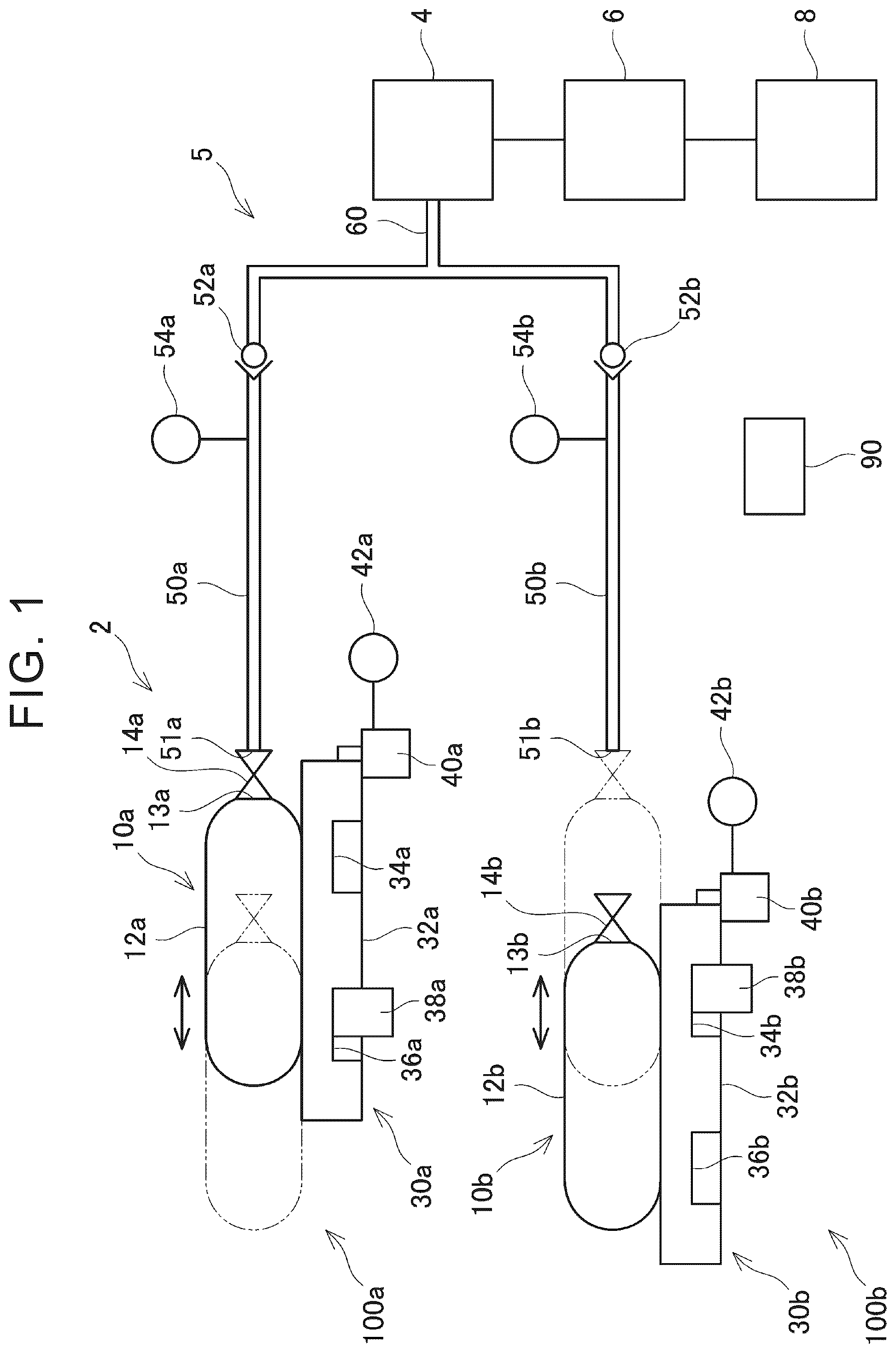
is a diagram schematically illustrating a gas supply device according to an embodiment;
is a flowchart (1) illustrating a method of replacing a gas tank according to an embodiment;
is a flow chart (2) illustrating a process for replacing a gas tank according to an embodiment of the present disclosure; and
is a sequence diagram illustrating a method of replacing a gas tank according to an embodiment.
DETAILED DESCRIPTION OF EMBODIMENTS
The gas supply device 2 of the embodiment will be described with reference to the drawings. As shown in , the gas supply device 2 of the embodiment includes a plurality of tank units (in the present embodiment, the first tank unit 100 a and the second tank unit 100 b ) and a control device 90 . The gas supply device 2 is a device that supplies gas to the gas consuming device 4 through the gas supply pipe 5 . The gas supplied to the gas consuming device 4 is, for example, hydrogen gas or oxygen gas. The gas supply device 2 may include three or more tank units.
The gas consuming device 4 is, for example, a fuel cell that consumes gas and generates electric power. The gas consuming device 4 is connected to a gas supply pipe 5 . The gas consuming device 4 (fuel cell) may be electrically connected to the power consuming device 6 . The gas consuming device 4 (fuel cell) is configured to be capable of supplying power generated by consuming gas to the power consuming device 6 . The type of the gas consuming device 4 and the type of the gas are not particularly limited.
The power consuming device 6 is, for example, an electrified vehicle motor that consumes power and operates. The power consuming device 6 consumes power supplied from the gas consuming device 4 (fuel cell). The power consuming device 6 may be electrically connected to a storage battery 8 different from the gas consuming device 4 (fuel cell). The storage battery 8 is configured to be capable of supplying electric power stored therein to the power consuming device 6 . The power consuming device 6 consumes power supplied from the storage battery 8 . The storage battery 8 is, for example, a lithium-ion battery.
The gas supply pipe 5 includes a first gas supply pipe 50 a , a second gas supply pipe 50 b , and a common gas supply pipe 60 . The gas supply device 2 introduces gas into the first gas supply pipe 50 a from the inlet 51 a of the first gas supply pipe 50 a . Similarly, the gas supply device 2 introduces the gas into the second gas supply pipe 50 b from the inlet 51 b of the second gas supply pipe 50 b . The inlet 51 a of the first gas supply pipe 50 a is opened to the outside when the first gas tank 10 a to be described later is not connected. Similarly, the inlet 51 b of the second gas supply pipe 50 b is opened to the outside when the second gas tank 10 b to be described later is not connected.
The first gas supply pipe 50 a is provided with a first check valve 52 a and a first pressure sensor 54 a . The first check valve 52 a allows gas to flow from the upstream side (the first gas tank 10 a side) to the downstream side (the gas consuming device 4 side) of the first gas supply pipe 50 a , and prohibits gas from flowing from the downstream side to the upstream side.
The first pressure sensor 54 a is provided on the upstream side (the first gas tank 10 a side) of the first check valve 52 a . The first pressure sensor 54 a detects the pressure of the gas in the first gas supply pipe 50 a upstream of the first check valve 52 a . The pressure detected by the first pressure sensor 54 a is transmitted to the control device 90 .
The second gas supply pipe 50 b is provided with a second check valve 52 b and a second pressure sensor 54 b . The second check valve 52 b and the second pressure sensor 54 b have the same configuration as the first check valve 52 a and the first pressure sensor 54 a , respectively, and thus detailed explanation thereof is omitted.
The first gas supply pipe 50 a and the second gas supply pipe 50 b merge at their downstream ends. The first gas supply pipe 50 a on the downstream side of the first check valve 52 a and the second gas supply pipe 50 b on the downstream side of the second check valve 52 b merge. The first gas supply pipe 50 a and the second gas supply pipe 50 b are connected to the common gas supply pipe 60 at their downstream ends. The downstream end of the common gas supply pipe 60 is connected to the gas consuming device 4 . The common gas supply pipe 60 supplies the gas sent from the first gas supply pipe 50 a or the second gas supply pipe 50 b to the gas consuming device 4 .
Next, the first tank unit 100 a will be described. The second tank unit 100 b has the same configuration as the first tank unit 100 a . Therefore, in the following description, the first tank unit 100 a will be mainly described, and the second tank unit 100 b will be given the same reference numerals as in the first tank unit 100 a , and detailed description thereof may be omitted. The configuration of the first tank unit 100 a is denoted by “a”, and the configuration of the second tank unit 100 b is denoted by “b”.
The first tank unit 100 a includes a first gas tank 10 a and a first movement device 30 a that moves the first gas tank 10 a . The first gas tank 10 a includes a first tank body 12 a and a first on-off valve 14 a . The first tank body 12 a stores the gas (for example, hydrogen gas) supplied to the gas consuming device 4 at a high pressure. The first tank body 12 a is connected to the first gas supply pipe 50 a via the first on-off valve 14 a.
The first on-off valve 14 a is provided on the gas-supply port 13 a of the first tank body 12 a . The first on-off valve 14 a opens and closes the gas-supply port 13 a of the first tank body 12 a . The first on-off valve 14 a is connected to the first gas supply pipe 50 a when the gas is supplied from the first gas tank 10 a to the gas consuming device 4 .
When the first on-off valve 14 a is connected to the first gas supply pipe 50 a , it seals the inlet 51 a of the first gas supply pipe 50 a . When the first on-off valve 14 a is opened in this condition, the gas in the first tank body 12 a is supplied to the gas consuming device 4 through the first gas supply pipe 50 a . In a state in which the first on-off valve 14 a is not connected to the first gas supply pipe 50 a (that is, a state in which it is separated from the first gas supply pipe 50 a ), the inlet 51 a of the first gas supply pipe 50 a is opened.
The first on-off valve 14 a opens when the first gas tank 10 a is in the first position (i.e., in the first condition), which will be described later. On the other hand, the first on-off valve 14 a is closed when the first gas tank 10 a is in the second position (i.e., in the second condition), which will be described later. The first on-off valve 14 a is closed when the first gas tank 10 a is in the third position (that is, in the third position) described later.
In the first gas tank 10 a , the first on-off valve 14 a is opened in a state in which the first on-off valve 14 a is connected to the first gas supply pipe 50 a (that is, in a state in which the first on-off valve 14 a seals the inlet 51 a of the first gas supply pipe 50 a ). Accordingly, the gas in the first tank body 12 a can be supplied to the gas consuming device 4 through the first gas supply pipe 50 a . On the other hand, when the first on-off valve 14 a is closed while the first on-off valve 14 a is connected to the first gas supply pipe 50 a , the gas in the first tank body 12 a is not supplied to the gas consuming device 4 .
The configuration for opening and closing the first on-off valve 14 a is not particularly limited. For example, the first on-off valve 14 a may be configured to open when the member inside the valve is pushed by the inlet 51 a of the first gas supply pipe 50 a . In this case, the first on-off valve 14 a may be configured to close the valve when the inlet 51 a of the first gas supply pipe 50 a does not push the member inside the valve.
The first gas tank 10 a having the above-described configuration can be transitioned between a first state, a second state, and a third state. In the first condition, gas is supplied from the first gas tank 10 a to the gas consuming device 4 . The first on-off valve 14 a is opened while the first on-off valve 14 a of the first gas tank 10 a is connected to the first gas supply pipe 50 a . Thus, the first state is a state in which the gas in the first tank body 12 a is supplied to the gas consuming device 4 through the first gas supply pipe 50 a . In the first condition, the gas supplied from the first gas tank 10 a is consumed by the gas consuming device 4 . In the first condition, the first on-off valve 14 a is connected to the first gas supply pipe 50 a , so that the inlet 51 a of the first gas supply pipe 50 a is sealed. In the first state, the gas is supplied from the first gas tank 10 a to the first gas supply pipe 50 a , so that the pressure in the first gas supply pipe 50 a is increased.
In the second condition, no gas is supplied from the first gas tank 10 a to the gas consuming device 4 . In the second state, the first on-off valve 14 a is closed while the first on-off valve 14 a is connected to the first gas supply pipe 50 a , so that the gas in the first tank body 12 a is not supplied to the gas consuming device 4 . In the second condition, the gas remaining in the first gas supply pipe 50 a is consumed by the gas consuming device 4 . In the second condition, the first on-off valve 14 a is connected to the first gas supply pipe 50 a , so that the inlet 51 a of the first gas supply pipe 50 a is sealed. In the second condition, the gas remaining in the first gas supply pipe 50 a is consumed by the gas consuming device 4 , so that the pressure in the first gas supply pipe 50 a gradually decreases.
In the third condition, no gas is supplied from the first gas tank 10 a to the gas consuming device 4 . In the third state, the first on-off valve 14 a is disengaged from the first gas supply pipe 50 a in a state where the first on-off valve 14 a is closed. In the third condition, the first on-off valve 14 a is separated from the first gas supply pipe 50 a , whereby the inlet 51 a of the first gas supply pipe 50 a is opened without being sealed.
Next, a first movement device 30 a of the first tank unit 100 a will be described. The first movement device 30 a includes a first movement table 32 a , a first motor 40 a , a first movement restricting member 38 a , and a first position sensor 42 a . The first movement device 30 a may move the first gas tank 10 a to a first position, a second position, and a third position. The first position is a position at which the first gas tank 10 a is in the first condition described above. The second position is a position at which the first gas tank 10 a is in the second state described above, and the third position is a position at which the first gas tank 10 a is in the third state described above.
The first movement table 32 a supports the first gas tank 10 a while the first on-off valve 14 a of the first gas tank 10 a is directed toward the first gas supply pipe 50 a . The first movement table 32 a is moved by driving the first motor 40 a while the first gas tank 10 a is mounted. The first movement table 32 a is driven by the first motor 40 a so as to move toward the first gas supply pipe 50 a or to move away from the first gas supply pipe 50 a . The first motor 40 a is, for example, a stepping motor.
The first movement table 32 a includes a front side recessed portion 34 a and a rear side recessed portion 36 a into which the first movement restricting member 38 a is inserted. The front side recessed portion 34 a is provided closer to the first gas supply pipe 50 a than the rear side recessed portion 36 a.
The first movement restricting member 38 a is configured to be movable up and down by driving of a solenoid. The first movement restricting member 38 a is inserted into the front side recessed portion 34 a or the rear side recessed portion 36 a of the first movement table 32 a by moving upward. When the first movement restricting member 38 a is inserted into the front side recessed portion 34 a or the rear side recessed portion 36 a , the movement of the first movement table 32 a is restricted. In the following, this state is sometimes referred to as a regulated state.
Further, the first movement restricting member 38 a moves downward to exit from the front side recessed portion 34 a or the rear side recessed portion 36 a of the first movement table 32 a . When the first movement restricting member 38 a exits from the front side recessed portion 34 a or the rear side recessed portion 36 a , the restriction of the movement of the first movement table 32 a is released. Hereinafter, this state may be referred to as a release state.
The first position sensor 42 a is connected to, for example, the first motor 40 a , and detects the position of the first movement table 32 a by detecting the number of steps of the first motor 40 a . The first position sensor 42 a can detect the position of the first gas tank 10 a by detecting the position of the first movement table 32 a . The position detected by the first position sensor 42 a is transmitted to the control device 90 .
The control device 90 includes, for example, a CPU, ROM, a RAM, and the like, and executes various controls and processes related to the gas supply device 2 in accordance with predetermined programming. For example, the control device 90 controls the first movement device 30 a and the second movement device 30 b to move the first gas tank 10 a and the second gas tank 10 b . Accordingly, the first gas tank 10 a and the second gas tank 10 b are transitioned.
Next, methods of exchanging the gas tank (the first gas tank 10 a and the second gas tank 10 b ) in the gas supply device 2 will be described. and are flow charts illustrating a method of replacing a gas tank, and is a sequence diagram illustrating a method of replacing a gas tank. In the initial state of the embodiment, it is assumed that the first gas tank 10 a and the second gas tank 10 b are in the third position (that is, the third state).
As shown in , in S 2 of the embodiment, the first movement device 30 a of the gas supply device 2 sets the first movement restricting member 38 a to the released state, and the second movement device 30 b sets the second movement restricting member 38 b to the released state.
As shown in , in a subsequent S 4 , the first movement device 30 a and the second movement device 30 b move the first gas tank 10 a and the second gas tank 10 b from the third position to the second position (that is, transition from the third state to the second state), respectively. When the first gas tank 10 a and the second gas tank 10 b are in the second condition, the first gas tank 10 a is connected to the first gas supply pipe 50 a , and the second gas tank 10 b is connected to the second gas supply pipe 50 b (see ).
In the following S 6 , the first movement device 30 a and the second movement device 30 b regulate the first movement restricting member 38 a and the second movement restricting member 38 b , respectively.
In a subsequent S 8 , the first movement device 30 a and the second movement device 30 b move the first gas tank 10 a and the second gas tank 10 b from the second position to the first position (i.e., transit from the second state to the first state), respectively. When the first gas tank 10 a is in the first condition, the first on-off valve 14 a is opened, and the gas is supplied from the first gas tank 10 a into the first gas supply pipe 50 a . Similarly, when the second gas tank 10 b is in the first condition, the second on-off valve 14 b is opened, and the gas is supplied from the second gas tank 10 b into the second gas supply pipe 50 b.
Subsequently, in S 10 , the control device 90 compares the detected pressure of the first pressure sensor 54 a with the detected pressure of the second pressure sensor 54 b (that is, compares the pressure of the gas in the first gas supply pipe 50 a with the pressure of the gas in the second gas supply pipe 50 b ). Then, the control device 90 determines 10 a , 10 b of gas tanks to be used based on the comparison. For example, the control device 90 determines to use the first gas tank 10 a when the detected pressure of the first pressure sensor 54 a is lower than the detected pressure of the second pressure sensor 54 b . Alternatively, the control device 90 determines to use the second gas tank 10 b when the detected pressure of the second pressure sensor 54 b is lower than the detected pressure of the first pressure sensor 54 a . In the present embodiment, it is assumed that the first gas tank 10 a is used.
In a subsequent S 12 , the first movement device 30 a and the second movement device 30 b move the first gas tank 10 a and the second gas tank 10 b from the first position to the second position (i.e., transit from the first state to the second state), respectively. When the first gas tank 10 a is in the second state, the first on-off valve 14 a is closed, and when the second gas tank 10 b is in the second state, the second on-off valve 14 b is closed.
As shown in , in a subsequent S 14 , the first movement device 30 a moves the first gas tank 10 a determined to be used in S 10 from the second position to the first position (i.e., transitions from the second state to the first state). On the other hand, the second movement device 30 b keeps the unused second gas tank 10 b in the second position (i.e., the second condition).
When the gas tank to be used (the first gas tank 10 a in the present embodiment) is in the first condition, the first on-off valve 14 a is opened, and the gas is supplied from the first gas tank 10 a to the gas consuming device 4 through the first gas supply pipe 50 a . Further, when the gas is consumed by the gas consuming device 4 , the quantity of the gas in the first tank body 12 a of the first gas tank 10 a is decreased, and the pressure of the gas in the first gas supply pipe 50 a is gradually decreased.
Subsequently, in S 16 , the control device 90 monitors whether or not the detected pressure of the pressure sensor on the gas tank-side in use falls below a predetermined first reference pressure. In the present embodiment, in S 16 , the control device 90 monitors whether or not the detected pressure of the first pressure sensor 54 a on 10 a of the first gas tank falls below a predetermined first reference pressure. The detected pressure of the first pressure sensor 54 a on the first gas tank 10 a is the pressure of the gas in the first gas supply pipe 50 a . If the detected pressure of the first pressure sensor 54 a drops below the first reference pressure (YES at S 16 ), the process proceeds to S 18 and if not dropped below the first reference pressure (NO at S 16 ), the process waits at S 16 . When the detected pressure of the first pressure sensor 54 a falls below the first reference pressure (see T 2 of ), it means that the amount of gas in the first tank body 12 a of the first gas tank 10 a falls below a predetermined reference amount.
In S 18 after YES in S 16 , the first movement device 30 a moves the in-use first gas tank 10 a from the first position to the second position (i.e., transitions from the first state to the second state). Here, even if the first gas tank 10 a in use moves to the second position (that is, transitions to the second state), the gas still remains in the first gas supply pipe 50 a immediately after that. Therefore, the gas remaining in the first gas supply pipe 50 a is supplied to the gas consuming device 4 , and the gas is consumed by the gas consuming device 4 . When the gas remaining in the first gas supply pipe 50 a is consumed by the gas consuming device 4 , the pressure of the gas in the first gas supply pipe 50 a gradually decreases.
Subsequently, in S 20 , the control device 90 monitors whether or not the detected pressure of the first pressure sensor 54 a (that is, the pressure of the gas in the first gas supply pipe 50 a ) on the same side as the above-described S 16 falls below the predetermined second reference pressure. The second reference pressure is a pressure that is less than the first reference pressure in S 16 . If the detected pressure of the first pressure sensor 54 a drops below the second reference pressure (YES at S 20 ), the process proceeds to S 22 , and if not dropped below the second reference pressure (NO at S 20 ), the process waits at S 20 . When the detected pressure of the first pressure sensor 54 a falls below the second reference pressure (see T 4 of ), it means that the quantity of the gas remaining in the first gas supply pipe 50 a has sufficiently decreased.
Subsequently, in S 22 , the second movement device 30 b moves the other unused gas tank (the second gas tank 10 b in the present embodiment) from the second position to the first position (that is, transitions from the second state to the first state). When the second gas tank 10 b is in the first condition, the second on-off valve 14 b is opened, and the gas is supplied from the second gas tank 10 b to the gas consuming device 4 through the second gas supply pipe 50 b . Further, when the gas is consumed by the gas consuming device 4 , the quantity of the gas in the second tank body 12 b of the second gas tank 10 b is decreased, and the pressure of the gas in the second gas supply pipe 50 b is gradually decreased.
Subsequently, in S 24 , the first movement device 30 a releases the first movement restricting member 38 a . In a subsequent S 26 , the first movement device 30 a moves the used first gas tank 10 a from the second position to the third position (i.e., transitions from the second state to the third state). When the first gas tank 10 a is in the third condition, the first on-off valve 14 a is separated from the first gas supply pipe 50 a . In the following S 28 , the first movement device 30 a sets the first movement restricting member 38 a to the restricting condition.
The gas supply device 2 and the method of replacing the gas tank according to the embodiment have been described above. As is obvious from the above explanation, in the replacement of the gas tank, the gas in the first gas supply pipe 50 a is consumed by the gas consuming device 4 . As a result, after the pressure of the gas in the first gas supply pipe 50 a drops below the second reference pressure, the first gas tank 10 a is brought from the second state to the third state (see S 20 , S 26 of ).
According to this configuration, when the first gas tank 10 a is removed from the first gas supply pipe 50 a , the first gas tank 10 a can be removed after the pressure of the gas remaining in the first gas supply pipe 50 a decreases. Accordingly, it is possible to suppress generation of noise caused by the pressure of the gas in the first gas supply pipe 50 a when the first gas tank 10 a is removed.
The gas supply device 2 includes a first movement device 30 a that moves the first gas tank 10 a . According to this configuration, it is possible to switch the status of the first gas tank 10 a with little effort.
Further, in the method of replacing the gas tank, the gas in the first gas supply pipe 50 a is consumed by the gas consuming device 4 , so that the pressure of the gas in the first gas supply pipe 50 a is reduced to less than the second reference pressure, and then the second gas tank 10 b is put into the first state. According to this configuration, after the gas remaining in the first gas supply pipe 50 a is consumed, the gas can be supplied to the gas consuming device 4 from the second gas tank 10 b that differs from the first gas tank 10 a.
In the configuration of the embodiment, the first gas supply pipe 50 a on the downstream side of the first check valve 52 a and the second gas supply pipe 50 b on the downstream side of the second check valve 52 b merge. According to this configuration, it is possible to reduce the gas supplied from the first gas tank 10 a into the first gas supply pipe 50 a from flowing backward through the second gas supply pipe 50 b . Similarly, it is possible to reduce the gas supplied from the second gas tank into the second gas supply pipe 50 b from flowing backward through the first gas supply pipe 50 a.
Correspondence
The process of S 14 of the embodiment (see ) is an example of the “first step” described in the claims. Further, the process of S 18 (see ) is an example of the “second step”, the process of S 26 is an example of the “third step”, and the process of S 22 is an example of the “fourth step”.
Modification
After S 18 shown in , the first gas tank 10 a may be in a second position (i.e., in a second condition). In this case, the control device 90 may supply power from the storage battery 8 to the power consuming device 6 without supplying power from the gas consuming device 4 (fuel cell) to the power consuming device 6 . For example, the control device 90 switches the switches to cut off the energization between the gas consuming device 4 (fuel cell) and the power consuming device 6 , and to energize the storage battery 8 and the power consuming device 6 .
When the gas consuming device 4 is a fuel cell and the first gas tank 10 a is in the second state after S 18 , the fuel cell is in a state in which power is generated by consuming the gas remaining in the first gas supply pipe 50 a . In this state, it is considered that the power generation amount of the fuel cell is small. Therefore, at this time, by supplying power from the storage battery 8 to the power consuming device 6 without supplying power from the fuel cell to the power consuming device 6 , sufficient power can be supplied to the power consuming device 6 .
Although specific examples of the disclosure have been described in detail above, the examples are merely examples and do not limit the scope of claims. The technique described in the claims includes various modifications and variations of the specific examples exemplified above. The technical elements described in this specification or in the drawings exhibit technical utility alone or in various combinations, and are not limited to the combinations described in the claims at the time of filing. Further, the technology illustrated in the present specification or the drawings can achieve a plurality of objects at the same time, and has technical usefulness by achieving one of the objects.
Figures (4)
Citations
This patent cites (12)
- US8459399
- US2006/0065214
- US2006/0118175
- US2009/0272590
- US2019/0140291
- US2020/0217456
- US2022/0410701
- US2023/0115169
- US2009-270707
- US2023-056869
- US2023-056951
- US2023-056952