Rotary Actuator for Flight Control Surface
Abstract
A rotary actuator for a flight control surface includes a first electric motor connected to a first geartrain having planetary gearsets in series and a first drive gear driven by the first electric motor via the first geartrain. The first geartrain and the first drive gear define a first powertrain. The rotary actuator also includes a second electric motor connected to a second geartrain having planetary gearsets in series. The second geartrain is separate from the first geartrain. The rotary actuator further includes a second drive gear driven by the second electric motor via the second geartrain. The second geartrain and the second drive gear define a second powertrain that is coaxial with the first powertrain. Additionally, the rotary actuator includes an output shaft parallel to the first and second powertrains. The output shaft is driven simultaneously via the first and second drive gears.
Claims (18)
1 . A rotary actuator for a flight control surface, comprising: a first electric motor drivably connected to a first geartrain having at least two planetary gearsets arranged in series; a first drive gear driven by the first electric motor via the first geartrain, wherein the first geartrain and the first drive gear define a first powertrain; a second electric motor drivably connected to a second geartrain having at least two planetary gearsets arranged in series, wherein the second geartrain is separate from the first geartrain; a second drive gear driven by the second electric motor via the second geartrain, wherein the second geartrain and the second drive gear define a second powertrain that is arranged coaxially with the first powertrain; and an output shaft driven simultaneously via the first drive gear and the second drive gear, wherein the first electric motor and the second electric motor are axially adjacent to each other, such that the first and second electric motors are positioned axially between the first geartrain and the second geartrain.
6 . A rotary actuator for moving a flight control surface of an aircraft, comprising: a first electric motor drivably connected to a first geartrain having a plurality of planetary gearsets arranged in series; a first drive gear driven by the first electric motor via the first geartrain, wherein the first geartrain and the first drive gear define a first powertrain; and an output shaft arranged parallel to the first powertrain and configured to be driven by the first drive gear, the output shaft having a first sector gear that is engaged with the first drive gear.
15 . A rotary actuator, comprising: a first powertrain that includes a first electric motor, a first geartrain operably coupled with the first electric motor and having at least one gearset, and a first drive gear operably coupled with the first electric motor via the first geartrain; a second powertrain that includes a second electric motor, a second geartrain operably coupled with the second electric motor and having at least one gearset, and a second drive gear operably coupled with the second electric motor via the second geartrain, wherein the first electric motor is positioned axially adjacent to the second electric motor, the first geartrain is positioned axially adjacent to the first electric motor, and the second geartrain is positioned axially adjacent to the second electric motor, such that the first and second electric motors are positioned axially between the first and second geartrains; and an output shaft arranged parallel to the first and second powertrains and configured to be driven by the first and second powertrains.
Show 15 dependent claims
2 . The rotary actuator of claim 1 , wherein the first drive gear and the second drive gear are arranged at axial outer ends of the first powertrain and the second powertrain, respectively.
3 . The rotary actuator of claim 1 , wherein the first and second geartrains each comprise three planetary gearsets.
4 . The rotary actuator of claim 1 , wherein the output shaft is configured to rotate less than one revolution.
5 . The rotary actuator of claim 1 , wherein the output shaft further comprises: a first sector gear arranged at a first end of the output shaft and engaged with the first drive gear; and a second sector gear arranged at a second end of the output shaft and engaged with the second drive gear.
7 . The rotary actuator of claim 6 , wherein a full stroke of the rotary actuator prompts less than a full revolution of the output shaft.
8 . The rotary actuator of claim 6 , further comprising: a second electric motor drivably connected to a second geartrain having at least one gearset; and a second drive gear driven by the second electric motor via the second geartrain, wherein the second geartrain and the second drive gear define a second powertrain, wherein the second powertrain is operably coupled with the output shaft, such that the first and second powertrains are configured to simultaneously drive the output shaft.
9 . The rotary actuator of claim 8 , wherein the at least one gearset comprises: at least one planetary gearset.
10 . The rotary actuator of claim 9 , wherein the at least one planetary gearset comprises: a plurality of planetary gearsets arranged in series.
11 . The rotary actuator of claim 8 , wherein the first and second electric motors are axially adjacent to each other.
12 . The rotary actuator of claim 11 , wherein the first geartrain is axially adjacent the first electric motor opposite the second electric motor.
13 . The rotary actuator of claim 12 , wherein the second geartrain is axially adjacent the second electric motor opposite the first electric motor.
14 . The rotary actuator of claim 6 , wherein the first geartrain comprises three planetary gearsets.
16 . The rotary actuator of claim 15 , wherein the at least one gearset of the first geartrain comprises at least one planetary gearset, and the at least one gearset of the second geartrain comprises at least one planetary gearset.
17 . The rotary actuator of claim 16 , wherein the at least one planetary gearset of the first geartrain comprises a plurality of planetary gearsets arranged in series, and the at least one planetary gearset of the second geartrain comprises a plurality of planetary gearsets arranged in series.
18 . The rotary actuator of claim 15 , wherein driven rotation of the output shaft is configured to move a flight control surface of an aircraft.
Full Description
Show full text →
CROSS-REFERENCE TO RELATED APPLICATIONS
This application claims the benefit of priority under 35 U.S.C. § 119 of U.S. Provisional Application No. 63/547,457, filed on Nov. 6, 2023, the entire contents of which are incorporated herein by reference.
FIELD OF THE DISCLOSURE
This disclosure is generally related to an actuator for a flight control surface of an aircraft.
BACKGROUND OF THE DISCLOSURE
Actuators, such as pistons and solenoids, can be used in a variety of aerospace applications to move a flight control surface to a desired location, position, or angle. Flight control surfaces can include, but are not limited to, flaps, ailerons, spoilers, slats, elevators, rudders, and tabs.
SUMMARY OF THE DISCLOSURE
According to a first aspect of the present disclosure, a rotary actuator for a flight control surface includes a first electric motor drivably connected to a first geartrain having at least two planetary gearsets arranged in series and a first drive gear driven by the first electric motor via the first geartrain. The first geartrain and the first drive gear define a first powertrain. The rotary actuator also includes a second electric motor drivably connected to a second geartrain having at least two planetary gearsets arranged in series. The second geartrain is separate from the first geartrain. The rotary actuator further includes a second drive gear driven by the second electric motor via the second geartrain. The second geartrain and the second drive gear define a second powertrain that is arranged coaxially with the first powertrain. Additionally, the rotary actuator includes an output shaft that is driven simultaneously via the first drive gear and the second drive gear.
Embodiments of the first aspect of the disclosure can include any one or a combination of the following features:
•
• the first electric motor and the second electric motor are axially adjacent to each other; • the first drive gear and the second drive gear are arranged at axial outer ends of the first powertrain and the second powertrain, respectively; • the first and second geartrains each comprise three planetary gearsets; • the output shaft is configured to rotate less than one revolution; and • the output shaft further comprises a first sector gear arranged at a first end of the output shaft and engaged with the first drive gear and a second sector gear arranged at a second end of the output shaft and engaged with the second drive gear.
According to a second aspect of the present disclosure, a rotary actuator for moving a flight control surface of an aircraft includes a first electric motor drivably connected to a first geartrain having a plurality of planetary gearsets arranged in series, a first drive gear driven by the first electric motor via the first geartrain, and an output shaft arranged parallel to the first powertrain and configured to be driven by the first drive gear. The first geartrain and the first drive gear define a first powertrain.
Embodiments of the second aspect of the disclosure can include any one or a combination of the following features:
•
• a full stroke of the rotary actuator prompts less than a full revolution of the output shaft; • the output shaft further comprises a first sector gear that is engaged with the first drive gear; • the rotary actuator further comprises a second electric motor drivably connected to a second geartrain having at least one gearset, and a second drive gear driven by the second electric motor via the second geartrain, wherein the second geartrain and the second drive gear define a second powertrain, wherein the second powertrain is operably coupled with the output shaft, such that the first and second powertrains are configured to simultaneously drive the output shaft; • the at least one gearset comprises at least one planetary gearset; • the at least one planetary gearset comprises a plurality of planetary gearsets arranged in series; • the first and second electric motors are axially adjacent to each other; • the first geartrain is axially adjacent the first electric motor opposite the second electric motor; • the second geartrain is axially adjacent the second electric motor opposite the first electric motor; and • the first geartrain comprises three planetary gearsets.
According to a third aspect of the present disclosure, a rotary actuator includes a first powertrain that includes a first electric motor, a first geartrain operably coupled with the first electric motor and having at least one gearset, and a first drive gear operably coupled with the first electric motor via the first geartrain. The rotary actuator also includes a second powertrain that includes a second electric motor, a second geartrain operably coupled with the second electric motor and having at least one gearset, and a second drive gear operably coupled with the second electric motor via the second geartrain. The first electric motor is positioned axially adjacent to the second electric motor, the first geartrain is positioned axially adjacent to the first electric motor, and the second geartrain is positioned axially adjacent to the second electric motor, such that the first and second electric motors are positioned axially between the first and second geartrains. The rotary actuator further includes an output shaft arranged parallel to the first and second powertrains and configured to be driven by the first and second powertrains.
Embodiments of the third aspect of the disclosure can include any one or a combination of the following features:
•
• the at least one gearset of the first geartrain comprises at least one planetary gearset, and the at least one gearset of the second geartrain comprises at least one planetary gearset; • the at least one planetary gearset of the first geartrain comprises a plurality of planetary gearsets arranged in series, and the at least one planetary gearset of the second geartrain comprises a plurality of planetary gearsets arranged in series; and • driven rotation of the output shaft is configured to move a flight control surface of an aircraft.
These and other features, advantages, and objects of the present disclosure will be further understood and appreciated by those skilled in the art by reference to the following specification, claims, and appended drawings.
BRIEF DESCRIPTION OF THE DRAWINGS
In the drawings:
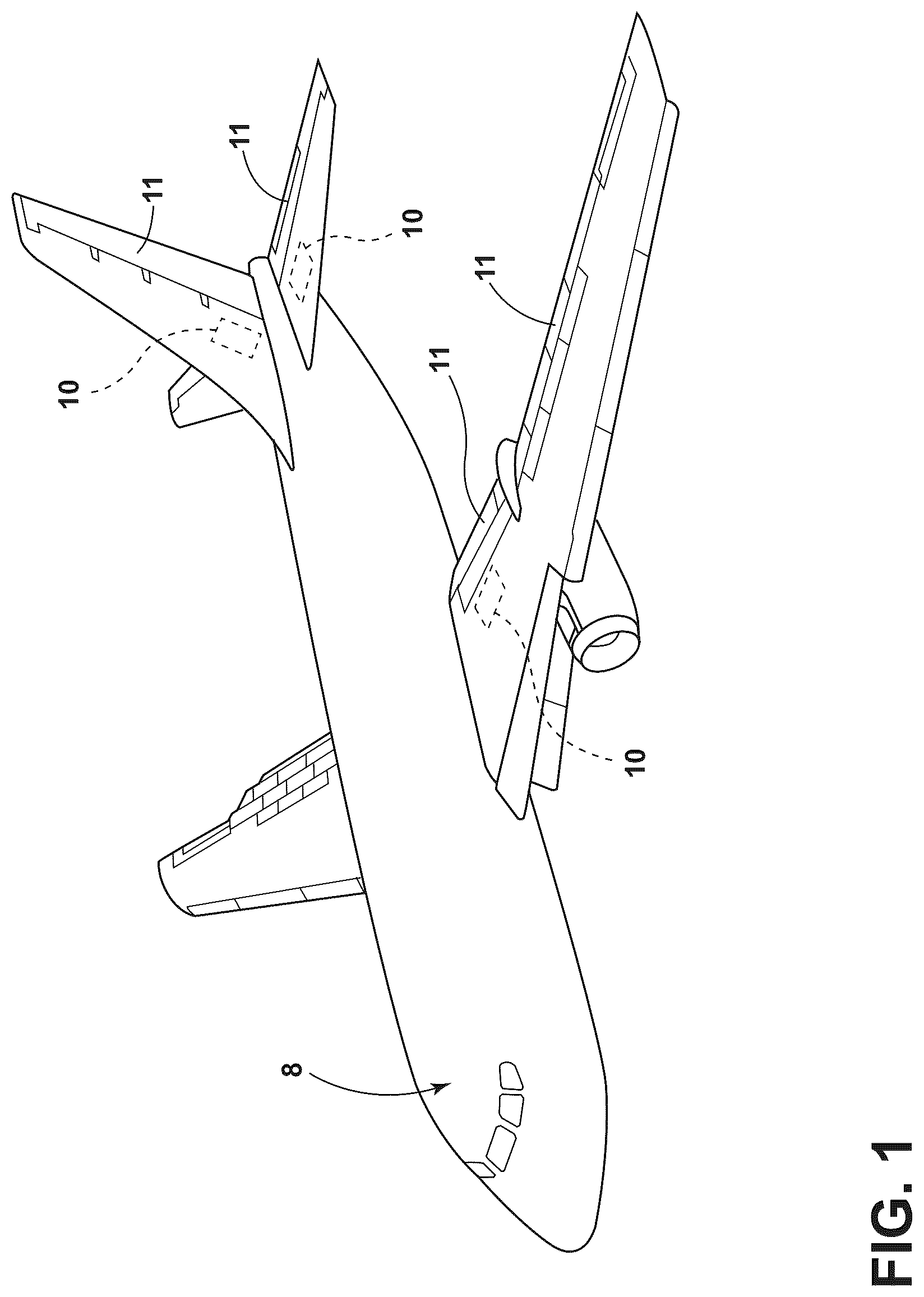
is a perspective view of an aircraft that includes a plurality of rotary actuators, according to one embodiment.
is a perspective view of a rotary actuator for a flight control surface, according to one embodiment.
is a perspective view of a portion of the rotary actuator of , illustrating a first electric motor and a first powertrain of the rotary actuator, according to one embodiment.
is a cross-sectional view of the rotary actuator of taken at line IV-IV, illustrating first and second electric motors, and first and second powertrains, according to one embodiment.
is an elevational view of a portion of a rotary actuator, illustrating a gearing interface of a drive gear of a powertrain of the rotary actuator and a sector gear of an output shaft of the rotary actuator, according to one embodiment.
is a perspective view of a series arrangement of planetary gearsets for a rotary actuator, according to one embodiment.
is an exploded perspective view of a series arrangement of planetary gearsets for a rotary actuator, according to one embodiment.
The components in the figures are not necessarily to scale, emphasis instead being placed upon illustrating the principles described herein.
DETAILED DESCRIPTION
Additional features and advantages of the disclosure will be set forth in the detailed description which follows and will be apparent to those skilled in the art from the description, or recognized by practicing the disclosure as described in the following description, together with the claims and appended drawings.
As used herein, the term “and/or,” when used in a list of two or more items, means that any one of the listed items can be employed by itself, or any combination of two or more of the listed items can be employed. For example, if a composition is described as containing components A, B, and/or C, the composition can contain A alone; B alone; C alone; A and B in combination; A and C in combination; B and C in combination; or A, B, and C in combination.
In this document, relational terms, such as “first” and “second,” “top” and “bottom,” and the like, are used solely to distinguish one entity or action from another entity or action, without necessarily requiring or implying any actual such relationship or order between such entities or actions.
For purposes of this disclosure, the term “coupled” (in all of its forms: couple, coupling, coupled, etc.) generally means the joining of two components (electrical or mechanical) directly or indirectly to one another. Such joining may be stationary in nature or movable in nature. Such joining may be achieved with the two components (electrical or mechanical) and/or any additional intermediate members. Such joining may include members being integrally formed as a single unitary body with one another (i.e., integrally coupled) or may refer to joining of two components. Such joining may be permanent in nature, or may be removable or releasable in nature, unless otherwise stated.
The terms “substantial,” “substantially,” and variations thereof as used herein are intended to note that a described feature is equal or approximately equal to a value or description. For example, a “substantially planar” surface is intended to denote a surface that is planar or approximately planar. Moreover, “substantially” is intended to denote that two values are equal or approximately equal. In some embodiments, “substantially” may denote values within about 10% of each other, such as within about 5% of each other, or within about 2% of each other.
As used herein, the terms “the,” “a,” or “an,” mean “at least one,” and should not be limited to “only one” unless explicitly indicated to the contrary. Thus, for example, reference to “a component” includes embodiments having two or more such components unless the context clearly indicates otherwise.
As used herein, the term “axial” and derivatives thereof, such as “axially,” shall be understood to refer to a direction along the axis of a shaft configured to rotate in operation of the apparatus described herein. Further, the term “radial” and derivatives thereof, such as “radially,” shall be understood in relation to the axis of the aforementioned shaft. For example, “radially outboard” refers to further away from the axis, while “radially inboard” refers to nearer to the axis.
Referring now to , a rotary actuator 10 is disclosed. The rotary actuator 10 may be configured to operate a flight control surface 11 of an aircraft 8 , in some embodiments, as illustrated exemplarily in . A variety of types of aircrafts 8 (e.g., plane, jet, drone, etc.) and flight control surfaces 11 (e.g., flaps, ailerons, spoilers, slats, elevators, rudders, and tabs, etc.) are contemplated. The rotary actuator 10 includes a first electric motor 12 A that, when energized, is configured to drive rotation of a first drive gear 24 A in either a first direction D 1 or a second direction D 2 . The rotary actuator 10 can include a second electric motor 12 B in addition to the first electric motor 12 A. In such embodiments, the first and second electric motors 12 A, 12 B are configured to simultaneously rotate the respective first drive gear 24 A and a respective second drive gear 24 B in either the first direction D 1 or the second direction D 2 . The first and second drive gears 24 A, 24 B engage respective first and second sector gears 26 A, 26 B arranged on an output shaft 28 . Rotation of the first and second drive gears 24 A, 24 B in the first direction D 1 causes rotation of the first and second sector gears 26 A, 26 B (and thus the output shaft 28 ) in the second direction D 2 . Likewise, rotation of the first and second drive gears 24 A, 24 B in the second direction D 2 causes rotation of the first and second sector gears 26 A, 26 B (and thus the output shaft 28 ) in the first direction D 1 .
The first electric motor 12 A is operably coupled with a first geartrain 14 A. The first geartrain 14 A includes at least one gearset 15 . The at least one gearset 15 may include a plurality of gearsets 15 . In some embodiments, the at least one gearset 15 includes at least one planetary gearset 15 . In the embodiment illustrated in , the first geartrain 14 A includes a plurality of planetary gearsets 15 arranged in series. In the illustrated embodiment, the first electric motor 12 A includes a first shaft 44 A that is operably connected to the first series arrangement of planetary gearsets 15 that form the first geartrain 14 A, which includes a first planetary gearset 16 , a second planetary gearset 18 , and a third planetary gearset 20 . The first shaft 44 A is rotationally (and drivably) fixed to a sun gear of the first planetary gearset 16 ; a planetary carrier of the first planetary gearset 16 is rotationally fixed to a sun gear of the second planetary gearset 18 ; a planetary carrier of the second planetary gearset 18 is rotationally fixed to a sun gear of the third planetary gearset 20 ; and a planetary carrier of the third planetary gearset 20 is rotationally fixed to a first transition piece 34 A that is rotationally fixed to the first drive gear 24 A. In summary, the first electric motor 12 A drives the first drive gear 24 A via the intervening first geartrain 14 A. Internally toothed ring gears 46 , 48 of the planetary gearsets 16 , 18 , 20 can be at least one of fixed to, directly integrated with, and rotatably arranged within an elongated casing 13 , as operably needed. The first electric motor 12 A, the first geartrain 14 A, the first transition piece 34 A, and the first drive gear 24 A form a first powertrain 60 A.
The second electric motor 12 B is operably coupled with a second geartrain 14 B. The second geartrain 14 B includes at least one gearset 15 . The at least one gearset 15 may include a plurality of gearsets 15 . In some embodiments, the at least one gearset 15 includes at least one planetary gearset 15 . In the embodiment illustrated in , the second geartrain 14 B includes a plurality of planetary gearsets 15 arranged in series. In the illustrated embodiment, the second electric motor 12 B includes a second shaft 44 B that is operably connected to the second series arrangement of planetary gearsets 15 that form the second geartrain 14 B, which include first, second, and third planetary gearsets 16 , 18 , 20 . The second shaft 44 B is rotationally (and drivably) fixed to a sun gear of the first planetary gearset 16 ; a planetary carrier of the first planetary gearset 16 is rotationally fixed to a sun gear of the second planetary gearset 18 ; a planetary carrier of the second planetary gearset 18 is rotationally fixed to a sun gear of the third planetary gearset 20 ; and a planetary carrier of the third planetary gearset 20 is rotationally fixed to a second transition piece 34 B that is rotationally fixed to the second drive gear 24 B. In summary, the second electric motor 12 B drives the second drive gear 24 B via the intervening second geartrain 14 B. Internally toothed ring gears 46 , 48 of the planetary gearsets 16 , 18 , 20 can be at least one of fixed to, directly integrated with, and rotatably arranged within the elongated casing 13 , as operably needed. The second electric motor 12 B, the second geartrain 14 B, the second transition piece 34 B, and the second drive gear 24 B form a second powertrain 60 B.
The first and second powertrains 60 A, 60 B are coaxial and/or aligned with each other within the elongated casing 13 . The elongated casing 13 can include a first piece 13 A and a second piece 13 B that are joined together by a mounting 36 . The first electric motor 12 A is axially adjacent to the second electric motor 12 B. In some implementations, the first and second electric motors 12 A, 12 B are arranged at an axial inner-most portion of the aligned first and second powertrains 60 A, 60 B and the first and second drive gears 24 A, 24 B are arranged at an axial outer-most portion of the aligned first and second powertrains 60 A, 60 B. The first and second powertrains 60 A, 60 B may be in a parallel drive arrangement for the output shaft 28 , as illustrated exemplarily in . In the illustrated embodiment, the axis about which the first and second electric motors 12 A, 12 B drive the first and second shafts 44 A, 44 B is parallel to the axis about which the output shaft 28 rotates.
As illustrated in , the first powertrain 60 A includes the first electric motor 12 A, the first geartrain 14 A, and the first drive gear 24 A. The second powertrain 60 B includes the second electric motor 12 B, the second geartrain 14 B, and the second drive gear 24 B. The first and second powertrains 60 A, 60 B are arranged relative to each other, such that the first electric motor 12 A is positioned axially adjacent to the second electric motor 12 B. Further, the first geartrain 14 A is positioned axially adjacent to the first electric motor 12 A, and the second geartrain 14 B is positioned axially adjacent to the second electric motor 12 B, such that the first and second electric motors 12 A, 12 B are positioned axially between the first and second geartrains 14 A, 14 B. In the illustrated embodiment, the first and second drive gears 24 A, 24 B are positioned at axial ends of the first and second powertrains 60 A, 60 B, respectively, opposite each other. As such, the first and second electric motors 12 A, 12 B and the first and second geartrains 14 A, 14 B are positioned axially between the first and second drive gears 24 A, 24 B.
The first and second powertrains 60 A, 60 B are supported within a housing 32 via rolling element bearings 40 . The output shaft 28 is supported within the housing 32 via rolling element bearings 42 . The rolling element bearings 40 , 42 can provide both radial and axial support. Any suitable bearing can be utilized in place of the rolling element bearings 40 , 42 shown within the figures. In some embodiments, separate bearings for such radial and axial support can be implemented. For ease of assembly, the output shaft 28 can be split into a first output shaft piece 29 A that is rotationally and axially fixed to a second output shaft piece 29 B via an output shaft coupler 30 . The elongated casing 13 can be attached to the housing 32 via any suitable means, including, but not limited to, welding, press-fitting, or fastening.
In an exemplary embodiment, the first powertrain 60 A and the second powertrain 60 B can each be configured to accommodate a design torque requirement of the output shaft 28 that is required to actuate the flight control surface 11 . Therefore, if one of the first or second electric motors 12 A, 12 B fails, the output shaft 28 , and thus, the corresponding flight control surface 11 remains operable. In some embodiments, the first powertrain 60 A and the second powertrain 60 B can be configured to accommodate the design torque requirement of the output shaft 28 only when the output torques of the first and second electric motors 12 A, 12 B are combined.
The first and second sector gears 26 A, 26 B each have teeth cut along a sector of a circumference in order to fulfill functional requirements while offering reduced packaging space. In an exemplary embodiment, the output shaft 28 rotates less than one revolution in either of the first direction D 1 or second direction D 2 . In some embodiments, the combined rotation of the output shaft 28 in the first direction D 1 and the second direction D 2 is less than one revolution. In some implementations, singular or combined rotations of the output shaft 28 can be greater than one revolution.
The gear ratios achieved by the first and second geartrains 14 A, 14 B, the first and second drive gears 24 A, 24 B, and the first and second sector gears 26 A, 26 B facilitate adequate torque magnification (and speed reduction, if desired) to adjust a flight control surface 11 that is mechanically or operably connected to the output shaft 28 , or further, integrated with the output shaft 28 . It is contemplated that the rotary actuator 10 may be used in applications other than adjustment of flight control surfaces 11 of an aircraft 8 .
Referring now to , a first series arrangement of planetary gearsets in an exemplary embodiment of the first geartrain 14 A is shown that includes a fourth planetary gearset 22 . This arrangement can provide a higher torque output than the first series of arrangement of planetary gearsets relative to the embodiment of the first geartrain 14 A illustrated in that contains only three planetary gearsets. Various numbers of series-arranged planetary gearsets that achieve a required torque and/or speed requirement are contemplated.
While example embodiments are described above, it is not intended that these embodiments describe all possible forms encompassed by the claims. The words used in the specification are words of description rather than limitation, and it is understood that various changes can be made without departing from the spirit and scope of the disclosure. As previously described, the features of various embodiments can be combined to form further embodiments of the disclosure that may not be explicitly described or illustrated. While various embodiments could have been described as providing advantages or being preferred over other embodiments or prior art implementations with respect to one or more desired characteristics, those of ordinary skill in the art recognize that one or more features or characteristics can be compromised to achieve desired overall system attributes, which depend on the specific application and implementation. These attributes can include, but are not limited to cost, strength, durability, life cycle cost, marketability, appearance, packaging, size, serviceability, weight, manufacturability, ease of assembly, etc. As such, to the extent any embodiments are described as less desirable than other embodiments or prior art implementations with respect to one or more characteristics, these embodiments are not outside the scope of the disclosure and can be desirable for particular applications.
LIST OF REFERENCE NUMERALS
•
• 8 Aircraft • 10 Rotary actuator • 11 Flight control surface • 12 A First electric motor • 12 B Second electric motor • 13 Elongated casing • 13 A First piece • 13 B Second piece • 14 A First geartrain • 14 B Second geartrain • 15 Gearset • 16 First planetary gearset • 18 Second planetary gearset • 20 Third planetary gearset • 22 Fourth planetary gearset • 24 A First drive gear • 24 B Second drive gear • 26 A First sector gears • 26 B Second sector gears • 28 Output shaft • 29 A First output shaft piece • 29 B Second output shaft piece • 30 Output shaft coupler • 32 Housing • 34 A First transition piece • 34 B Second transition piece • 36 Mounting • 40 Rolling element bearings • 42 Rolling element bearings • 44 A First shaft • 44 B Second shaft • 46 Ring gears • 48 Ring gears • 60 A First powertrain • 60 B Second powertrain • D 1 First direction • D 2 Second direction
Figures (7)
Citations
This patent cites (13)
- US2371607
- US4637272
- US4751855
- US4979700
- US5214972
- US5518466
- US6875145
- US8336817
- US9701397
- US9976639
- US10082442
- US10281033
- US11073195