Fluid Control Device and Substrate Processing Apparatus Including the Same
Abstract
A fluid control device includes: a fluid block having a first channel extending from an inlet to an outlet and a second channel above and in communication with the first channel, the fluid block including a bending cover configured to cover the second channel to thereby block fluid from flowing from the inlet to the outlet of the first channel; and a valve having a hollow portion, a first hole connected to the hollow portion, a piston in the hollow portion, and an elastic body configured to elastically support the piston, the valve configured to pressurize the bending cover, wherein the fluid block includes a guide plate below the bending cover, wherein the fluid block includes a first passage through which control gas flows, and wherein the valve includes a second passage connecting the first passage to the hollow portion.
Claims (20)
1. A fluid control device comprising: a fluid block having a first channel extending from an inlet at a first side of the fluid block to an outlet at a second side of the fluid block and a second channel above and in communication with the first channel, the fluid block including a bending cover configured to cover the second channel to thereby block fluid from flowing from the inlet to the outlet of the first channel; and a valve having a hollow portion and a first hole connected to the hollow portion, and including a piston in the hollow portion and an elastic body configured to elastically support the piston, the valve configured to pressurize the bending cover; wherein the fluid block includes a guide plate below the bending cover, the guide plate extending upwardly through the first channel, wherein the fluid block includes a first passage through which control gas flows, and wherein the valve includes a second passage connecting the first passage to the hollow portion.
16. A substrate processing apparatus comprising: a fluid supplier configured to supply process fluid; a first fluid control device configured to control the supply of the process fluid; and a chamber, into which the process fluid flows, configured to process a substrate, wherein the first fluid control device comprises: a fluid block having a first channel extending from an inlet at a first side of the fluid block to an outlet at a second side of the fluid block and a second channel above and in communication with the first channel, the fluid block including a bending cover configured to cover the second channel to thereby block fluid from flowing from the inlet to the outlet of the first channel; and a valve having a hollow portion and a first hole connected to the hollow portion, and having a piston in the hollow portion and an elastic body configured to elastically support the piston, the valve configured to pressurize the bending cover, wherein the fluid block includes a guide plate below the bending cover, the guide plate extending upwardly through the first channel, wherein the process fluid flows into the chamber through the first channel, wherein the fluid block includes a first passage through which control gas flows, and wherein the valve includes a second passage connecting the first passage and the hollow portion.
20. A substrate processing apparatus comprising: a fluid supply configured to supply process fluid; a first fluid control device configured to control a flow rate of the process fluid; and a chamber, into which the process fluid flows, configured to process a substrate, wherein the first fluid control device comprises: a fluid block having a first channel extending from an inlet at a first side of the fluid block to an outlet at a second side of the fluid block and a second channel above and in communication with the first channel, the fluid block including a bending cover configured to cover the second channel to thereby block fluid from flowing from the inlet to the outlet of the first channel; and a valve having a hollow portion and a first hole connected to the hollow portion, and including a piston in the hollow portion and an elastic body configured to elastically support the piston, the valve configured to pressurize the bending cover, wherein the process fluid flows into the chamber through the first channel and includes at least one of AsH 3 , PH 3 , H 2 Se, SiH 4 , and H 2 S, wherein the fluid block includes a guide plate below the bending cover, the guide plate extending upwardly through the first channel, wherein the piston includes a central portion and a first protruding portion extending outwardly from an outer surface of the central portion, wherein at least a part of the central portion extends through the first hole and contacts the bending cover, wherein the first protruding portion is in contact with a sidewall that at least partially defines the hollow portion, wherein the fluid block includes a first passage through which control gas flows, wherein the valve includes a second passage connecting the first passage to the hollow portion, and wherein a size of a cross-section of the first passage is the same as a size of a cross-section of the second passage.
Show 17 dependent claims
2. The fluid control device of claim 1 , wherein the piston includes a central portion and a first protruding portion extending outwardly from an outer surface of the central portion, wherein a part of the central portion extends through the first hole and contacts the bending cover, and wherein the first protruding portion is in contact with a sidewall of the valve that at least partially defines the hollow portion.
3. The fluid control device of claim 2 , wherein the hollow portion is divided into a first area and a second area by the first protruding portion, wherein the elastic body is in the first area of the hollow portion, and wherein the second passage is connected to the second area of the hollow portion.
4. The fluid control device of claim 3 , wherein the first hole is connected to the first area of the hollow portion, and wherein the piston is configured to descend toward the guide plate when the control gas flows into the second area.
5. The fluid control device of claim 4 , wherein the bending cover is spaced apart from the guide plate before the control gas flows into the second area, and wherein the bending cover is pressurized by the piston and contacts the guide plate when the control gas flows into the second area.
6. The fluid control device of claim 3 , wherein the first hole is connected to the second area of the hollow portion, and wherein the piston is configured to ascend away from the guide plate when the control gas flows into the second area of the hollow portion.
7. The fluid control device of claim 6 , wherein the bending cover is pressurized by the piston and in contact with the guide plate before the control gas flows into the second area of the hollow portion, and wherein the bending cover is spaced apart from the guide plate when the control gas flows into the second area of the hollow portion.
8. The fluid control device of claim 1 , wherein the piston includes a central portion and first and second protruding portions extending outwardly from an outer surface of the central portion, wherein a part of the central portion extends through the first hole and contacts the bending cover, wherein the first protruding portion is spaced apart from the second protruding portion, wherein the first protruding portion is in contact with a sidewall of the valve that at least partially defines the hollow portion, and wherein the second protruding portion is in contact with the sidewall of the valve.
9. The fluid control device of claim 8 , wherein the hollow portion includes first, second, and third areas divided by the first and second protruding portions, wherein the elastic body is in the first area of the hollow portion, wherein the second area is between the first area of the hollow portion and the third area of the hollow portion, wherein the second passage is connected to the third area of the hollow portion, and wherein the central portion further includes a third passage connecting the second area and the third area.
10. The fluid control device of claim 9 , wherein the first hole is connected to the first area of the hollow portion, and wherein the piston is configured to descend toward the guide plate when the control gas flows into the second and third areas.
11. The fluid control device of claim 9 , wherein the first hole is connected to the third area of the hollow portion, and wherein the piston is configured to ascend away from the guide plate when the control gas flows into the second and third areas.
12. The fluid control device of claim 1 , wherein an area of a cross-section of the first passage is the same as an area of a cross-section of the second passage.
13. The fluid control device of claim 1 , wherein a cross-section of the first passage is circular, and wherein a cross-section of the second passage is circular.
14. The fluid control device of claim 1 , wherein the first passage of the fluid block penetrates through the fluid block, one end of the first passage is positioned at a side of the fluid block, and the other end of the first passage is positioned at an upper surface of the fluid block.
15. The fluid control device of claim 1 , further including a sealing portion between the first passage and the second passage.
17. The substrate processing apparatus of claim 16 , wherein the process fluid includes at least one of AsH 3 , PH 3 , H 2 Se, SiH 4 , and H 2 S.
18. The substrate processing apparatus of claim 16 , wherein the process fluid includes at least one of N 2 , O 2 , H 2 , Ar, and He.
19. The substrate processing apparatus of claim 16 , further comprising: a divert line; and a second fluid control device on the divert line and configured to control fluid flowing through the divert line.
Full Description
Show full text →
CROSS-REFERENCE TO RELATED APPLICATION
This application is based on and claims priority under 35 U.S.C. § 119 to Korean Patent Application No. 10-2022-0155802, filed on Nov. 18, 2022, in the Korean Intellectual Property Office, the disclosure of which is incorporated by reference herein in its entirety.
BACKGROUND
The inventive concept relates to a fluid control device and a substrate processing apparatus including the same.
In order to manufacture semiconductor devices, various processes, such as oxidation processes, photolithography, etching, thin film deposition, metalization, electrical die sorting (EDS), and packaging, are performed on wafers. As the miniaturization of semiconductor devices increases, the need for high-precision control of semiconductor process conditions increases. Particularly, in thin film deposition processes, a uniform thickness of deposition layers through high-precision control of process fluid is a key element of semiconductor devices.
SUMMARY
The inventive concept provides a fluid control device of which damage or deformation is prevented during preventive maintenance and breakdown maintenance and a substrate processing apparatus including the same.
The inventive concept provides a fluid control device in which pressure of control gas is constant and a substrate processing apparatus including the same.
In addition, aspects of the inventive concept is not limited to those mentioned above, and additional aspects of the inventive concept may be clearly understood by those skilled in the art from the following description.
According to an aspect of the inventive concept, there is provided a fluid control device including a fluid block having a first channel extending from an inlet at a first side of the fluid block to an outlet at a second side of the fluid block and a second channel above and in communication with the first channel, the fluid block including a bending cover configured to cover the second channel to thereby block fluid from flowing from the inlet to the outlet of the first channel, and a valve having a hollow portion and a first hole connected to the hollow portion, and including a piston in the hollow portion and an elastic body configured to elastically support the piston, the valve configured to pressurize the bending cover, wherein the fluid block includes a guide plate below the bending cover, wherein the fluid block includes a first passage through which control gas flows, and wherein the valve includes a second passage connecting the first passage to the hollow portion.
According to another aspect of the inventive concept, there is provided a substrate processing apparatus including a fluid supplier configured to supply process fluid, a first fluid control device configured to control the supply of the process fluid, and a chamber, into which the process fluid flows, configured to process a substrate, wherein the first fluid control device includes a fluid block having a first channel extending from a first side of the fluid block to an opposite second side of the fluid block, and a valve including a hollow portion, a first hole connected to the hollow portion, a piston in the hollow portion, and an elastic member configured to elastically support the piston, wherein the process fluid flows into the chamber through the first channel, wherein the fluid block includes a first passage through which control gas flows, and wherein the valve includes a second passage connecting the first passage and the hollow portion.
According to an aspect of the inventive concept, there is provided a substrate processing apparatus including: a fluid supply configured to supply process fluid, a first fluid control device configured to control a flow rate of the process fluid, and a chamber, into which the process fluid flows, configured to process a substrate, wherein the first fluid control device includes: a fluid block having a first channel extending from a first side to a second side of the fluid block and a second channel extending from an upper surface of the fluid block to the first channel, the fluid block including a bendable cover configured to cover the second channel, and a valve having a hollow portion and a first hole connected to the hollow portion, the valve including a piston in the hollow portion and an elastic body configured to elastically support the piston, the valve configured to pressurize the bendable cover, wherein the process fluid flows into the chamber through the first channel and includes at least one of AsH 3 , PH 3 , H 2 Se, SiH 4 , and H 2 S, wherein the fluid block includes a guide plate below the bending cover, wherein the piston includes a central portion and a first protruding portion extending outwardly from an outer surface of the central portion, wherein at least a part of the central portion extends through the first hole and contacts the bendable cover, wherein the first protruding portion is in contact with a sidewall that at least partially defines the hollow portion, wherein the fluid block includes a first passage through which control gas flows, wherein the valve includes a second passage connecting the first passage to the hollow portion, and wherein a size of a cross section of the first passage is the same as a size of a cross section of the second passage.
BRIEF DESCRIPTION OF THE DRAWINGS
Embodiments will be more clearly understood from the following detailed description taken in conjunction with the accompanying drawings in which:
is a side cross-sectional view schematically illustrating a fluid control device according to an embodiment;
is a side cross-sectional view schematically illustrating the fluid control device of ;
is a side cross-sectional view schematically illustrating a state in which control gas flows into the fluid control device of ;
is a side cross-sectional view schematically illustrating a state in which control gas flows into the fluid control device of ;
is a side cross-sectional view schematically illustrating a fluid control device according to an embodiment;
is a side cross-sectional view schematically illustrating a fluid control device according to an embodiment;
is a conceptual diagram schematically illustrating a substrate processing apparatus according to an embodiment; and
is a conceptual diagram schematically illustrating a substrate processing apparatus according to an embodiment.
DETAILED DESCRIPTION
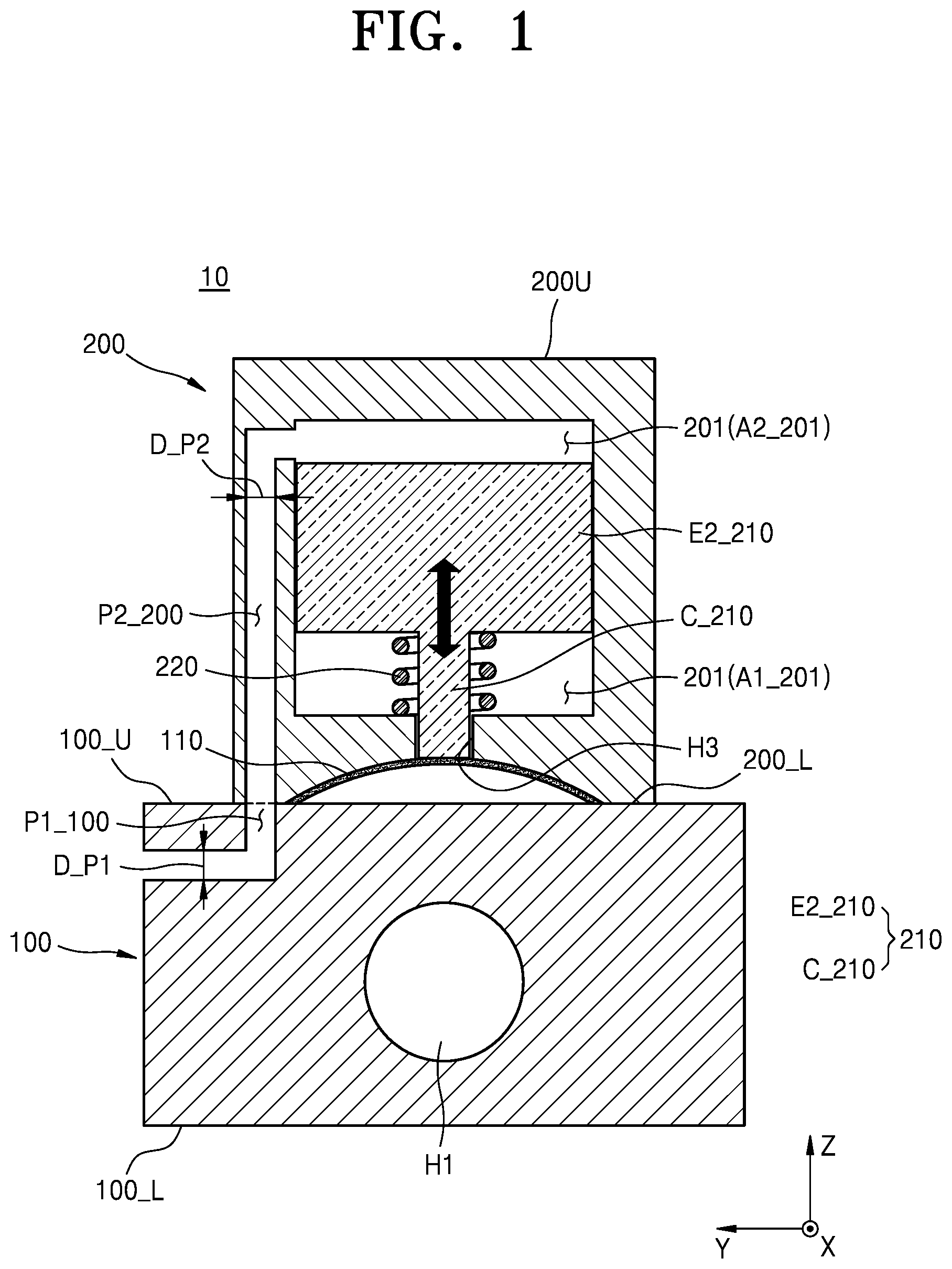
is a side cross-sectional view schematically illustrating a fluid control device according to an embodiment. is a side cross-sectional view schematically illustrating the fluid control device of . are side cross-sectional views viewed from different directions.
Referring to , a fluid control device 10 may include a fluid block 100 and a valve 200 .
The fluid block 100 of the fluid control device 10 may provide a passage through which process fluid may flow. The fluid block 100 may have a first channel H 1 extending through the fluid block 100 from one side or a first side 100 _S 1 to the other side or a second side 100 _S 2 (e.g., opposite the first side 100 _S 1 ). The fluid block 100 may have a second channel H 2 therein extending from the first channel H 1 to an upper surface 100 _U of the fluid block 100 . The fluid block 100 may include a bending cover or bendable cover 110 covering the second channel H 2 . The fluid block 100 may include a guide plate E 1 _ 100 protruding from or extending from the sidewall forming the first channel H 1 toward the upper surface 100 _U. The guide plate E 1 _ 100 may be positioned under the bending cover 110 .
In some embodiments, the bending cover 110 may comprise elastic material. In some embodiments, the bending cover 110 is resilient. That is, the bending cover 110 may be deformed when an external force is applied thereto, and the bending cover 110 may return to its original shape due to its resilience when the external force is removed. In some embodiments, the bending cover 110 may be bent upward when the external force is removed, and the bending cover 110 may be bent downward when the external force is applied thereto. That is, a lower surface of the bending cover 110 may be spaced apart from an upper surface or upper portion of the second channel H 2 . In other words, there may be an empty space, extending from the second channel H 2 , under the bending cover 110 . In some embodiments, the bending cover 110 may be a diaphragm.
In some embodiments, the first channel H 1 may have a circular cross-section in a direction perpendicular to the direction in which the first channel H 1 extends. That is, the first channel H 1 may have a circular cross-section in the YZ plane. In other words, the first channel H 1 may have a cylindrical shape.
In some embodiments, the second channel H 2 may have a circular cross-section in a direction perpendicular to the direction in which the second channel H 2 extends. That is, the second channel H 2 may have a circular cross-section in the XY plane. In other words, the second channel H 2 may have a cylindrical shape.
In some embodiments, an end of the first channel H 1 exposed to or at one side 100 _S 1 of the fluid block 100 is an inlet through which the process fluid flows in, and an end of the first channel H 1 exposed to or at the other side 100 _S 2 of the fluid block 100 is an outlet through which the process fluid flows out, wherein the process fluid may flow in from one side 100 _S 1 of the fluid block 100 and flow out to the other side 100 _S 2 of the fluid block 100 . That is, the process fluid may flow inside the fluid block 100 through the first channel H 1 of the fluid block 100 as a passage.
In some embodiments, the guide plate E 1 _ 100 may extend to the upper surface 100 _U of the fluid block 100 , so that the upper surface of the guide plate E 1 _ 100 and the upper surface 100 _U of the fluid block 100 may be on the same plane or coplanar. In other words, the guide plate E 1 _ 100 may be positioned in the second channel H 2 . That is, the guide plate E 1 _ 100 may extend to the upper surface or upper portion of the second channel H 2 across the first channel H 1 .
In some embodiments, the process fluid may move from one side 100 _S 1 to the other side 100 _S 2 of the fluid block 100 through the first channel H 1 and the second channel H 2 . The guide plate E 1 _ 100 protruding from the sidewall forming the first channel H 1 may hinder the flow of the process fluid.
That is, when the process fluid passes through the first channel H 1 , the guide plate E 1 _ 100 positioned in the first channel H 1 may guide the movement of the process fluid to the second channel H 2 . The process fluid guided by the guide plate E 1 _ 100 in the first channel H 1 may move to the second channel H 2 connected to the first channel H 1 . The bending cover 110 covering the second channel H 2 may cause the process fluid that has moved to the second channel H 2 to flow over the guide plate E 1 _ 100 . The process fluid that has passed the guide plate E 1 _ 100 may flow back into the first channel H 1 and flow out to the other side 100 _S 2 of the fluid block 100 .
That is, the process fluid passing through the fluid block 100 may be guided along a preset flow path by the guide plate E 1 _ 100 located inside the first channel H 1 and the second channel H 2 . The flow-guided process fluid may pass under the bending cover 110 covering the second channel H 2 and flow out to the other side 100 _S 2 of the fluid block 100 . In other words, the process fluid may be routed by the guide plate E 1 _ 100 to pass through the first channel H 1 and the second channel H 2 , and the process fluid may flow in from one side 100 _S 1 of the fluid block 100 and flow out to the other side 100 _S 2 of the fluid block 100 .
In some embodiments, the bending cover 110 may contact the guide plate E 1 _ 100 when the bending cover 110 a in subjected to an external force is bent downward. That is, when an external force is applied to the bending cover 110 , an empty space, extending from the second channel H 2 , under the bending cover 110 may be removed.
When the bending cover 110 is in contact with the guide plate E 1 _ 100 , the process fluid which flows in from one side 100 _S 1 of the fluid block 100 may not flow out to the other side 100 _S 2 of the fluid block 100 because the path of the process fluid is blocked by the bending cover 110 and the guide plate E 1 _ 100 . That is, the movement path of the process fluid may be blocked by applying an external force to the bending cover 110 .
Specifically, the process fluid may flow in from one side 100 _S 1 of the fluid block 100 , and the flow of the process fluid may be guided by the guide plate E_ 100 while moving through the first channel H 1 . The process fluid, the flow of which is guided by the guide plate E 1 _ 100 , may move to the second channel H 2 . The flow of the process fluid that has moved to the second channel H 2 is restricted by the bending cover 110 and the guide plate E 1 _ 100 . The process fluid, the flow of which is restricted by the bending cover 110 and the guide plate E 1 _ 100 , may not flow out to the other side 100 _S 2 of the fluid block 100 . In other words, when the bending cover 110 is in contact with the guide plate E 1 _ 100 , the process fluid may not be supplied.
The fluid block 100 may include a first passage P 1 _ 100 . The first passage P 1 _ 100 may provide a path along which control gas or control fluid flows in from the outside of the fluid block 100 and flows out to the upper surface 100 _U of the fluid block 100 . In some embodiments, the first passage P 1 _ 100 may extend from one side 100 _S 1 of the fluid block 100 to the upper surface 100 _U of the fluid block 100 . In , the first passage P 1 _ 100 is formed perpendicular to the first channel H 1 at the end of the fluid block 100 , but is not limited thereto, and may include an area extending parallel to the first channel H 1 .
A cross-section of the first passage P 1 _ 100 in a direction perpendicular to the direction in which the first passage P 1 _ 100 extends may have a circular shape. That is, the first passage P 1 _ 100 may have a cylindrical shape. In some embodiments, the diameter D_P 1 of the first passage P 1 _ 100 may be about 1 millimeter (mm) to about 4 mm.
The valve 200 of the fluid control device 10 may pressurize the bending cover 110 . The valve 200 may have a hollow portion 201 and a first hole H 3 . The first hole H 3 connected to the hollow portion 201 may extend from a lower surface 200 _L of the valve 200 to the hollow portion 201 . The valve 200 may include a piston 210 and an elastic body or elastic member 220 . The piston 210 and the elastic body 220 may be located in the hollow portion 201 .
The piston 210 may have a central portion C_ 210 and a first protruding portion E 2 _ 210 . The first protruding portion E 2 _ 210 may protrude or extend outward from the outer surface of the central portion C_ 210 .
At least a part of the central portion C_ 210 of the piston 210 may pass through the first hole H 3 to come into contact with the bending cover 110 and apply an external force to the bending cover 110 . That is, at least a part of the central portion C_ 210 may protrude from or extend from the lower surface 200 _L of the valve 200 and come into contact with the bending cover 110 .
The first protruding portion E 2 _ 210 of the piston 210 may come into contact with a sidewall forming or at least partially defining the hollow portion 201 . That is, an end or side of the first protruding portion E 2 _ 210 may come into contact with a sidewall forming the hollow portion 201 . In other words, the hollow portion 201 may be divided into a first area A 1 _ 201 and a second area A 2 _ 201 by the first protruding portion E 2 _ 210 , wherein the first area A 1 _ 201 may be separated from the second area A 2 _ 201 by the first protruding portion E 2 _ 210 so that fluid does not move therebetween. That is, the first protruding portion E 2 _ 210 may separate the first area A 1 _ 201 and the second area A 2 _ 201 to block the communication between the first area A 1 _ 201 and the second area A 2 _ 201 .
The elastic body 220 of the valve 200 may have a spring shape. The elastic body 220 of the valve 200 may elastically support the piston 210 . The elastic body 220 of the valve 200 may be resilient. That is, the elastic body 220 may return to its original length when extended or contracted. In some embodiments, the elastic body 220 may be positioned between the first protruding portion E 2 _ 210 of the piston 210 and the lower surface forming the hollow portion 201 . That is, when the piston 210 moves downward after an external force is applied thereto, the length of the elastic body 220 may be reduced. When the external force applied to the piston 210 is removed, the elastic body 220 may return to its original length, thereby moving the piston 210 upward. only shows the elastic body is positioned under the first protruding portion E 2 _ 210 , but is not limited thereto, and may be positioned above the first protruding portion E 2 _ 210 .
The valve 200 may include a second passage P 2 _ 200 in communication with each of the first passage P 1 _ 100 and the hollow portion 201 . The second passage P 2 _ 200 may connect the first passage P 1 _ 100 to the hollow portion 201 . That is, the second passage P 2 _ 200 may provide a path along which the control gas having flowed out from the first passage P 1 _ 100 flows into the hollow portion 201 . In other words, the control gas may flow into the hollow portion 201 through the first passage P 1 _ 100 and the second passage P 2 _ 200 . In some embodiments, the control gas may flow in from the lower surface 200 _L of the valve 200 and may flow out to the hollow portion 201 through the second passage P 2 _ 200 .
A cross-section of the second passage P 2 _ 200 in a direction perpendicular to the direction in which the second passage P 2 _ 200 extends may have a circular shape. That is, the second passage P 2 _ 200 may have a cylindrical shape. In some embodiments, the diameter D_P 2 of the second passage P 2 _ 200 may be about 1 mm to about 4 mm.
In some embodiments, an area of a cross-section of the first passage P 1 _ 100 in a direction perpendicular to the direction in which the first passage P 1 _ 100 extends may be a first area. An area of a cross-section of the second passage P 2 _ 200 in a direction perpendicular to the direction in which the second passage P 2 _ 200 extends may be a second area. The first area may be the same as the second area. In other words, the diameter D_P 1 of the first passage P 1 _ 100 may be the same as the diameter D_P 2 of the second passage P 2 _ 200 . shows that the diameter D_P 1 of the first passage P 1 _ 100 is the same as the diameter D_P 2 of the second passage P 2 _ 200 , but is not limited thereto, and the diameter D_P 2 of the second passage P 2 _ 200 may be greater than the diameter D_P 1 of the first passage P 1 _ 100 .
In some embodiments, the hollow portion 201 may be divided into the first area A 1 _ 201 and the second area A 2 _ 201 by the first protruding portion E 2 _ 210 as a boundary therebetween. The first area A 1 _ 201 may be an area where the elastic body 220 is located, and the second area A 2 _ 201 may be an area in communication with the second passage P 2 _ 200 . That is, the hollow portion 201 is divided into multiple areas, and the area where the elastic body 220 is located may be different from the area in communication with the second passage P 2 _ 200 .
In some embodiments, the first area A 1 _ 201 may be connected to the first hole H 3 of the valve 200 , and the second area A 2 _ 201 may be connected to the second passage P 2 _ 200 . In other words, the first area A 1 _ 201 may be located below the second area A 2 _ 201 . That is, the first area A 1 _ 201 where the elastic body 220 is located may be located below the second area A 2 _ 201 .
When the control gas flows into the second area A 2 _ 201 , the pressure in the second area A 2 _ 201 may increase to apply an external force to the piston 210 in a direction from the second area A 2 _ 201 toward the first area A 1 _ 201 . The piston 210 subjected to an external force may be positioned adjacent to the lower surface forming the hollow portion 201 . That is, the piston 210 may move downward, and the central portion C_ 210 of the piston 210 may be positioned adjacent to the guide plate E 1 _ 100 . In other words, when the control gas flows into the second area A 2 _ 201 , the piston 210 may move downward to increase the volume of the second area A 2 _ 201 and decrease the volume of the first area A 1 _ 201 .
In the fluid control device 10 of the inventive concept, the first passage P 1 _ 100 and the second passage P 2 _ 200 through which the control gas is supplied may be located inside the fluid control device 10 . Since the first passage P 1 _ 100 and the second passage P 2 _ 200 through which the control gas is supplied are located inside the fluid control device 10 , damage, hardening, and deformation of the first passage P 1 _ 100 and the second passage P 2 _ 200 through which the control gas is supplied may be reduced during preventive maintenance (PM) or breakdown maintenance (BM). In addition, in the fluid control device 10 , the supply of the process fluid may be constant due to the reduction of damage, hardening, and deformation of the first passage P 1 _ 100 and the second passage P 2 _ 200 through which the control gas is supplied. For a substrate processing apparatus to which process fluid is constantly supplied, a high-quality substrate process may be performed.
is a side cross-sectional view schematically illustrating a state in which control gas flows into the fluid control device 10 of . is a side cross-sectional view schematically illustrating a state in which control gas flows into the fluid control device 10 of . are the side cross-sectional views viewed from different directions.
Referring to , an operation of the fluid control device 10 when the control gas flows into the fluid control device 10 is described. In , the path along which the control gas moves is indicated by dashed-arrows.
In some embodiments, before the control gas flows into the second area A 2 _ 201 , the elastic body 220 may have its original length, and the bending cover 110 may be spaced apart from the guide plate E 1 _ 100 . That is, before the control gas flows into the hollow portion 201 , the process fluid may move from one side 100 _S 1 to the other side 100 _S 2 of the fluid block 100 through the first channel H 1 and the second channel H 2 .
When the control gas flows into the second area A 2 _ 201 , the pressure in the second area A 2 _ 201 may increase to move the piston 210 in a direction from the second area A 2 _ 201 toward the first area A 1 _ 201 . When the piston 210 moves, the central portion C_ 210 of the piston 210 may move toward the guide plate E 1 _ 100 through the first channel H 1 and the second channel H 2 . When the central portion C_ 210 moves toward the guide plate E 1 _ 100 to apply an external force to a bending cover 110 a , the bending cover 110 a may contact the guide plate E 1 _ 100 . When the bending cover 110 a subjected to an external force contacts the guide plate E 1 _ 100 , the movement of the process fluid from one side 100 _S 1 to the other side 100 _S 2 of the fluid block 100 may be restricted.
In some embodiments, when the control gas flows into the second area A 2 _ 201 , the bending cover 110 a may contact the guide plate E 1 _ 100 . That is, when the control gas flows into the second area A 2 _ 201 , the piston 210 may move downward to apply an external force to the bending cover 110 a . The bending cover 110 a subjected to an external force by the piston 210 may be bent downward. The bending cover 110 a subjected to an external force may be bent downward to contact the guide plate E 1 _ 100 . That is, when the control gas flows into the second area A 2 _ 201 located adjacent to the upper surface 200 _U of the valve 200 , second area A 2 _ 201 may increase to move the piston 210 downward and the bending cover 110 a may contact the guide plate E 1 _ 100 .
In some embodiments, when the control gas flows into the second area A 2 _ 201 , the second area A 2 _ 201 may increase to compress or contract the elastic body 220 positioned between the lower surface of the first protruding portion E 2 _ 210 and the lower wall forming the hollow portion 201 . In other words, as the second area A 2 _ 201 increases, the first area A 1 _ 201 may decrease to contract the elastic body 220 positioned in the first area A 1 _ 201 . That is, when the control gas flows into the hollow portion 201 , the fluid control device 10 may be closed since the piston 210 moves toward the lower surface 200 _L and the bending cover 110 contacts the guide plate E 1 _ 100 .
When the inflow of the control gas into the second area A 2 _ 201 is stopped, the pressure in the second area A 2 _ 201 becomes equal to the pressure in the first area A 1 _ 201 and the elastic body 220 may relax or expand. In other words, when the pressure in the second area A 2 _ 201 decreases, the elastic body 220 may return to its original length and the second area A 2 _ 201 may decrease. That is, when the inflow of the control gas into the hollow portion 201 is stopped, the fluid control device 10 may be open since the piston 210 moves toward the upper surface 200 _U of the valve 200 and the bending cover 110 is spaced apart from the guide plate E 1 _ 100 .
In some embodiments, before the control gas flows into the hollow portion 201 , the process fluid may be supplied while the fluid control device 10 is open. After the control gas flows into the hollow portion 201 , the process fluid may be blocked while the fluid control device 10 is closed. That is, the fluid control device 10 may be open by default.
is a side cross-sectional view schematically illustrating a fluid control device 10 according to an embodiment.
Hereinafter, in the interest of brevity, descriptions that are substantially the same between the fluid control device 10 a of and the fluid control device 10 of may be omitted and differences therebetween are described.
Referring to , the fluid control device 10 a may further include a sealing portion or sealing member 300 . The sealing portion 300 may be located in an area where the first passage P 1 _ 100 is connected to the second passage P 2 _ 200 . The sealing portion 300 may suppress an outflow of the control gas in the area where the first passage P 1 _ 100 is connected to the second passage P 2 _ 200 . That is, the sealing portion 300 may be located in an area where the fluid block 100 including the first passage P 1 _ 100 comes into contact with the valve 200 including the second passage P 2 _ 200 . In some embodiments, the sealing portion 300 may include gasket sealing.
In the fluid control device 10 a of the inventive concept, the sealing portion 300 may prevent the control gas from flowing between the first passage P 1 _ 100 and the second passage P 2 _ 200 . That is, the sealing portion 300 may suppress the outflow of the control gas to keep the pressure in the second area A 2 _ 201 constant.
is a side cross-sectional view schematically illustrating a fluid control device according to an embodiment. is a side cross-sectional view schematically illustrating the fluid control device of . are side cross-sectional views viewed from different directions.
Referring to , a fluid control device 10 b may include the fluid block 100 and a valve 200 a . Hereinafter, in the interest of brevity, descriptions that are substantially the same between the fluid control device 10 b of and the fluid control device 10 of may be omitted and differences therebetween are described.
The fluid block 100 of the fluid control device 10 b may serve as a passage through which the process fluid flows. The fluid block 100 may have the first channel H 1 extending from one side 100 _S 1 to the other side 100 _S 2 through the fluid block 100 . The fluid block 100 may have the second channel H 2 therein extending from the first channel H 1 to the upper surface 100 _U of the fluid block 100 . The fluid block 100 may include the bending cover 110 a covering the second channel H 2 . The fluid block 100 may include the guide plate E 1 _ 100 protruding from the sidewall forming the first channel H 1 toward the upper surface 100 _U. The guide plate E 1 _ 100 may be located below the bending cover 110 a . In some embodiments, the fluid block 100 may include the fluid block 100 of .
The valve 200 a of the fluid control device 10 b may pressurize the bending cover 110 a . The valve 200 a may have the hollow portion 201 a and the first hole H 3 . The first hole H 3 connected to the hollow portion 201 a may extend from the lower surface 200 a _L of the valve 200 a to the hollow portion 201 a . The valve 200 a may include the piston 210 and the elastic body 220 .
The piston 210 and the elastic body 220 may be located in the hollow portion 201 a . The piston 210 may have the central portion C_ 210 and the first protruding portion E 2 _ 210 . The first protruding portion E 2 _ 210 may protrude outward from the outer surface of the central portion C_ 210 .
In some embodiments, the hollow portion 201 a may be divided into the first area A 1 _ 201 a and the second area A 2 _ 201 a by the first protruding portion E 2 _ 210 as a boundary therebetween. The first area A 1 _ 201 a may be an area where the elastic body 220 is located, and the second area A 2 _ 201 a may be an area where the second passage P 2 _ 200 a is located. That is, the hollow portion 201 a is divided into multiple areas, and the area where the elastic body 220 is located may be different from the area connected to the second passage P 2 _ 200 a.
In some embodiments, the second area A 2 _ 201 a may be connected to the first hole H 3 and the second passage P 2 _ 200 a of the valve 200 a , and the first area A 1 _ 201 a may be adjacent to the upper surface 200 a _U of the valve 200 a . In other words, the first area A 1 _ 201 a may be positioned above the second area A 2 _ 201 a . That is, the first area A 1 _ 201 a where the elastic body 220 is located may be positioned above the second area A 2 _ 201 a.
Since the elastic body 220 is positioned above the piston 210 , the piston 210 may pressurize the bending cover 110 a before an external force is applied to the piston 210 . The bending cover 110 a subjected to an external force may be bent downward. That is, the bending cover 110 a subjected to an external force may be bent downward to come into contact with the guide plate E 1 _ 100 . When the bending cover 110 a subjected to an external force contacts the guide plate E 1 _ 100 , the process fluid may not move from one side 100 _S 1 to the other side 100 _S 2 of the fluid block 100 .
In other words, before the control gas flows into the second area A 2 _ 201 a of the hollow portion 201 a , the fluid control device 10 b may be closed so that the movement of the process fluid is blocked. Before the control gas flows into the second area A 2 _ 201 a , the bending cover 110 a may contact the guide plate E 1 _ 100 .
In some embodiments, when the control gas flows into the second area A 2 _ 201 a , the bending cover 110 a may be spaced apart from the guide plate E 1 _ 100 . That is, when the control gas flows into the second area A 2 _ 201 a , the pressure in the second area A 2 _ 201 a increases so that the piston 210 may move in a direction from the second area A 2 _ 201 a toward the first area A 1 _ 201 a . In other words, the piston 210 may move toward the upper surface 200 a _U of the valve 200 a . When the piston 210 moves toward the upper surface 200 a _U of the valve 200 a , the external force applied to the bending cover 110 a may be removed, and the bending cover 110 a may be bent upward.
is a side cross-sectional view schematically illustrating a state in which control gas flows into the fluid control device 10 b of . is a side cross-sectional view schematically illustrating a state in which control gas flows into the fluid control device of . are the side cross-sectional views viewed from different directions.
Referring to , an operation of the fluid control device 10 b when the control gas flows into the fluid control device 10 b is described. In , the path along which the control gas moves is indicated by dashed-arrows.
When the control gas flows into the second area A 2 _ 201 a , the pressure in the second area A 2 _ 201 a may increase to move the piston 210 in a direction from the second area A 2 _ 201 a toward the first area A 1 _ 201 a . When the piston 210 moves, the central portion C_ 210 of the piston 210 may move toward the upper surface 200 a _U of the valve 200 a . When the central portion C_ 210 moves toward the upper surface 200 a _U of the valve 200 a , the external force applied to the bending cover 110 may be removed to separate the bending cover 110 from the guide plate E 1 _ 100 . When the bending cover 110 is spaced apart from the guide plate E 1 _ 100 , the process fluid may move from one side 100 _S 1 to the other side 100 _S 2 of the fluid block 100 .
In some embodiments, when the control gas flows into the second area A 2 _ 201 a , the bending cover 110 may be spaced apart from the guide plate E 1 _ 100 . That is, when the control gas flows into the second area A 2 _ 201 a , the external force applied to the bending cover 110 may be removed while the piston 210 moves upward. When the external force applied to the bending cover 110 is removed, the bending cover 110 may be bent upward. When the external force applied to the bending cover 110 is removed, the bending cover 110 may be bent upward and spaced apart from the guide plate E 1 _ 100 . That is, when the control gas flows into the second area A 2 _ 201 a located adjacent to the lower surface 200 a _L of the valve 200 a , the second area A 2 _ 201 a may increase and the piston 210 may move upward to separate the bending cover 110 from the guide plate E 1 _ 100 .
In some embodiments, as the control gas flows into the second area A 2 _ 201 a , the second area A 2 _ 201 a may increase and the elastic body 220 positioned between the upper surface of the first protruding portion E 2 _ 210 and the upper wall forming the hollow portion 201 may compress or contract. In other words, as the second area A 2 _ 201 a increases, the first area A 1 _ 201 a may decrease to contract the elastic body 220 positioned in the first area A 1 _ 201 a . That is, when the control gas flows into the second area A 2 _ 201 a , the fluid control device 10 b may be open since the piston 210 moves toward the upper surface 200 a _U of the valve 200 a and the bending cover 110 is spaced apart from the guide plate E 1 _ 100 .
When the inflow of the control gas into the second area A 2 _ 201 a is stopped, the pressure in the second area A 2 _ 201 a becomes equal to the pressure in the first area A 1 _ 201 a and the elastic body 220 may relax or expand. In other words, when the pressure in the second area A 2 _ 201 a decreases, the elastic body 220 a may return to its original length and the second area A 2 _ 201 a may decrease. That is, when the inflow of the control gas into the hollow portion 201 a is stopped, the fluid control device 10 may be closed since the piston 210 moves toward the lower surface 200 a _L of the valve 200 a and the bending cover 110 a contacts the guide plate E 1 _ 100 .
In some embodiments, before the control gas flows into the hollow portion 201 a , the process fluid may be blocked while the fluid control device 10 b is closed. That is, the fluid control device 10 b may be closed by default.
The first passage P 1 _ 100 and the second passage P 2 _ 200 a through which the control gas is supplied to the valve 200 a may be located inside the fluid control device 10 b of the inventive concept. Since the first passage P 1 _ 100 and the second passage P 2 _ 200 a through which the control gas is supplied are located inside the fluid control device 10 b , damage, hardening, and deformation of the first passage P 1 _ 100 and the second passage P 2 _ 200 a through which the control gas is supplied may be reduced during PM or BM.
is a side cross-sectional view schematically illustrating a fluid control device according to an embodiment.
Referring to , a fluid control device 10 c may include the fluid block 100 and a valve 200 b . Hereinafter, in the interest of brevity, descriptions that are substantially the same between the fluid control device 10 c of and the fluid control device 10 of may be omitted and differences therebetween are described.
In some embodiments, the fluid block 100 may be or include the fluid block 100 of .
The valve 200 b of the fluid control device 10 c may pressurize the bending cover 110 . The valve 200 b may have the hollow portion 201 b and the first hole H 3 . The first hole H 3 may be connected to the hollow portion 201 b and may extend from the lower surface 200 b _L of the valve 200 b to the hollow portion 201 b . The valve 200 b may include the piston 210 b and the elastic body 220 .
The piston 210 b and the elastic body 220 may be located in the hollow portion 201 b . The piston 210 b may include the central portion C_ 210 b , the first protruding portion E 2 _ 210 b , and a second protruding portion E 3 _ 210 b . The first protruding portion E 2 _ 210 b may protrude outward from the outer surface of the central portion C_ 210 b . The second protruding portion E 3 _ 210 b may protrude outward from the outer surface of the central portion C_ 210 b.
The first protruding portion E 2 _ 210 b may be spaced apart from the second protruding portion E 3 _ 210 b . In some embodiments, the second protruding portion E 3 _ 210 b may be closer to the upper surface 200 b _U of the valve 200 b than the first protruding portion E 2 _ 210 b.
At least a part of the central portion C_ 210 b of the piston 210 b may pass through the first hole H 3 and come into contact with the bending cover 110 . That is, at least a part of the central portion C_ 210 b may protrude from the lower surface 200 b _L of the valve 200 b and come into contact with the bending cover 110 .
The first protruding portion E 2 _ 210 b of the piston 210 b may come into contact with the sidewall forming the hollow portion 201 b . That is, the end or side of the first protruding portion E 2 _ 210 b may come into contact with the sidewall forming the hollow portion 201 b.
The second protruding portion E 3 _ 210 b of the piston 210 b may come into contact with the sidewall forming the hollow portion 201 b . That is, the end or side of the second protruding portion E 3 _ 210 b may come into contact with the sidewall forming the hollow portion 201 b.
The hollow portion 201 b may be divided into the first area A 1 _ 201 b , the second area A 2 _ 201 b , and a third area A 3 _ 201 b by the first protruding portion E 2 _ 210 b and the second protruding portion E 3 _ 210 b as boundaries therebetween. That is, the first protruding portion E 2 _ 210 b and the second protruding portion E 3 _ 210 b may divide the hollow portion 201 b into three areas. The first area A 1 _ 201 b may be an area where the elastic body 220 is located, the third area A 3 _ 201 b may be connected to the second passage P 2 _ 200 b , and the second area A 2 _ 201 b may be positioned between the first area A 1 _ 201 b and the third area A 3 _ 201 b.
In some embodiments, the first area A 1 _ 201 b and the second area A 2 _ 201 b may be separated by the first protruding portion E 2 _ 210 b so that fluid does not move therebetween. The second area A 2 _ 201 b and the third area A 3 _ 201 b may be separated by the second protruding portion E 3 _ 210 b.
The central portion C_ 210 b of the piston 210 b may include a third passage P 3 _ 210 b connecting the second area A 2 _ 201 b and the third area A 3 _ 201 b . That is, the control gas may move from the third area A 3 _ 201 b to the second area A 2 _ 201 b through the third passage P 3 _ 210 b . In other words, when the control gas flows into the third area A 3 _ 201 b , the control gas may move to the second area A 2 _ 201 b through the third passage P 3 _ 210 b.
In some embodiments, the first area A 1 _ 201 b may be connected to the first hole H 3 , and the third area A 3 _ 201 b may be connected to the second passage P 2 _ 200 b . That is, the first area A 1 _ 201 b may be adjacent to the lower surface 200 b _L of the valve 200 b , and the third area A 3 _ 201 b may be adjacent to the upper surface 200 b _U of the valve 200 b.
When the control gas flows into the third area A 3 _ 201 b through the second passage P 2 _ 200 b , the control gas may flow into the second area A 2 _ 201 b through the third passage P 3 _ 210 b . That is, when the control gas flows into the hollow portion 201 b , the pressure in the second area A 2 _ 201 b and the third area A 3 _ 201 b may be higher than that of the first area A 1 _ 201 b . When the pressure in the second area A 2 _ 201 b and the third area A 3 _ 201 b increases, the piston 210 b may move in a direction from the second area A 2 _ 201 b toward the first area A 1 _ 201 b.
In other words, when the control gas flows into the third area A 3 _ 201 b , the piston 210 b may come closer to the guide plate E 1 _ 100 in . That is, when the control gas flows into the third area A 3 _ 201 b , the movement of the process fluid may be blocked since the piston 210 b moves closer to the guide plate E 1 _ 100 and an external force is applied to the bending cover 110 to contact the guide plate E 1 _ 100 .
When the control gas does not flow into the hollow portion 201 b , the pressure in the second area A 2 _ 201 b and the third area A 3 _ 201 b may decrease and the elastic body 220 located in the first area A 1 _ 201 b may relax or expand. When the elastic body 220 is relaxed, the first area A 1 _ 201 b may increase and the piston 210 b may move in a direction from the first area A 1 _ 201 b toward the second area A 2 _ 201 b.
That is, when the control gas does not flow into the third area A 3 _ 201 b , the first area A 1 _ 201 b may increase and the bending cover 110 may be spaced apart from the guide plate E 1 _ 100 in . In other words, when the control gas does not flow into the third area A 3 _ 201 b , the bending cover 110 may be spaced apart from the guide plate E 1 _ 100 and the process fluid may move from one end to the other end of the fluid block 100 .
is a side cross-sectional view schematically illustrating a fluid control device according to an embodiment.
Hereinafter, in the interest of brevity, descriptions that are substantially the same between the fluid control device 10 d of and the fluid control device 10 b of may be omitted and differences therebetween are described.
Referring to , the fluid control device 10 d may include the fluid block 100 and a valve 200 c . In some embodiments, the fluid block 100 may be or include the fluid block 100 of .
The valve 200 c of the fluid control device 10 d may pressurize the bending cover 110 a . The valve 200 c may have the hollow portion 201 c and the first hole H 3 . The first hole H 3 may be connected to the hollow portion 201 c and may extend from the lower surface 200 c _L of the valve 200 c to the hollow portion 201 c . The valve 200 c may include a piston 210 c and the elastic body 220 .
The piston 210 c and the elastic body 220 may be located in the hollow portion 201 c . The piston 210 c may include the central portion C_ 210 c , the first protruding portion E 2 _ 210 c , and the second protruding portion E 3 _ 210 c . The first protruding portion E 2 _ 210 c may protrude or extend outward from the outer surface of the central portion C_ 210 c . The second protruding portion E 3 _ 210 c may protrude or extend outward from the outer surface of the central portion C_ 210 c.
In some embodiments, the first protruding portion E 2 _ 210 c and the second protruding portion E 3 _ 210 c may be or include the first protruding portion E 2 _ 210 b of and the second protruding portion E 3 _ 210 b of described with reference to .
The hollow portion 201 c may be divided into the first area A 1 _ 201 c , the second area A 2 _ 201 c , and the third area A 3 _ 201 c by the first protruding portion E 2 _ 210 c and the second protruding portion E 3 _ 210 c as boundaries therebetween. That is, the first protruding portion E 2 _ 210 c and the second protruding portion E 3 _ 210 c may divide the hollow portion 201 c into three areas. The first area A 1 _ 201 c may be an area where the elastic body 220 is located, the third area A 3 _ 201 c may be connected to the second passage P 2 _ 200 c , and the second area A 2 _ 201 c may be positioned between the first area A 1 _ 201 c and the third area A 3 _ 201 c.
In some embodiments, the first area A 1 _ 201 c and the second area A 2 _ 201 c may be separated by the second protruding portion E 3 _ 210 c so that fluid does not move therebetween. The second area A 2 _ 201 c and the third area A 3 _ 201 c may be separated by the first protruding portion E 2 _ 210 c.
The central portion C_ 210 c of the piston 210 c may include the third passage P 3 _ 210 c connecting the second area A 2 _ 201 c to the third area A 3 _ 201 c . That is, the control gas may move from the third area A 3 _ 201 c to the second area A 2 _ 201 c through the third passage P 3 _ 210 c . In other words, when the control gas flows into the third area A 3 _ 201 c , the control gas may move to the second area A 2 _ 201 c through the third passage P 3 _ 210 c.
In some embodiments, the first area A 1 _ 201 c may be located on the upper surface of the second protruding portion E 3 _ 210 c , and the third area A 3 _ 201 c may be connected to the first hole H 3 and the second passage P 2 _ 200 c . That is, the first area A 1 _ 201 c may be adjacent to the upper surface 200 c _U of the valve 200 c , and the third area A 3 _ 201 c may be adjacent to the lower surface 200 c _L of the valve 200 c.
When the control gas flows into the third area A 3 _ 201 c through the second passage P 2 _ 200 c , the control gas may flow into the second area A 2 _ 201 c through the third passage P 3 _ 210 c . That is, when the control gas flows into the hollow portion 201 c , the pressure in the second area A 2 _ 201 c and the third area A 3 _ 201 c may be higher than that of the first area A 1 _ 201 c . When the pressure in the second area A 2 _ 201 c and the third area A 3 _ 201 c increases, the piston 210 c may move in a direction from the second area A 2 _ 201 c toward the first area A 1 _ 201 c.
In other words, when the control gas flows into the third area A 3 _ 201 c , the piston 210 c may be spaced apart from the guide plate E 1 _ 100 in . That is, when the control gas flows into the third area A 3 _ 210 c , the bending cover 110 a from which the external force is removed may be spaced apart from the guide plate E 1 _ 100 as the piston 210 c is spaced apart from the guide plate E 1 _ 100 , and the process fluid may move from one end to the other end of the fluid block 100 .
When the control gas does not flow into the hollow portion 201 c , the pressure in the second area A 2 _ 201 c and the third area A 3 _ 201 c may decrease and the elastic body 220 located in the first area A 1 _ 201 c may relax or expand. When the elastic body 220 is relaxed, the first area A 1 _ 201 c may increase and the piston 210 c may move in a direction from the first area A 1 _ 201 c toward the second area A 2 _ 201 c.
That is, when the control gas does not flow into the third area A 3 _ 201 c , the first area A 1 _ 201 c may increase and the bending cover 110 a may contact the guide plate E 1 _ 100 in . In other words, when the control gas does not flow into the third area A 3 _ 201 c , the bending cover 110 a may contact the guide plate E 1 _ 100 and the flow of the process fluid may be restricted.
is a conceptual diagram schematically illustrating a substrate processing apparatus according to an embodiment.
Referring to , a substrate processing apparatus 1 may include a fluid supplier or fluid supply 20 , a first fluid control device 10 , and a chamber 30 .
The fluid supplier 20 of the substrate processing apparatus 1 may supply the process fluid 21 to the chamber 30 . The fluid supplier 20 may supply the process fluid 21 to the chamber 30 through the first fluid control device 10 . That is, the first fluid control device 10 may be arranged between the fluid supplier 20 and the chamber 30 .
In some embodiments, the process fluid 21 may include one of AsH 3 , PH 3 , H 2 Se, SiH 4 , and H 2 S. That is, the fluid supplier 20 may supply the process fluid required during the deposition process on substrates.
In some embodiments, the process fluid 21 may include at least one of N 2 , O 2 , H 2 , Ar, and He. That is, the fluid supplier 20 may supply the process fluid required during the purge process on substrates.
In some embodiments, the process fluid 21 may include at least one of Cl 2 , HCl, CHF 3 , CH 2 F 2 , CH 3 F, H 2 , BCL 3 , SiCl 4 , Br 2 , HBr, NF 3 , CF 4 , C 2 F 6 , C 4 F 8 , SF 6 , O 2 , SO 2 and COS. That is, the fluid supplier 20 may supply the etchant gas required during the dry etching process on substrates.
The first fluid control device 10 of the substrate processing apparatus 1 may adjust the flow rate of the process fluid 21 . When the first fluid control device 10 is open, the process fluid 21 may flow from the fluid supplier 20 to the chamber 30 . When the first fluid control device 10 is closed, the process fluid 21 may not flow from the fluid supplier 20 to the chamber 30 .
In some embodiments, the first fluid control device 10 may include the fluid block 100 in and the valve 200 in . The first fluid control device 10 may include the fluid control devices 10 , 10 a , 10 b , 10 c , and 10 d described above with reference to to 11 .
In some embodiments, the process fluid 21 may flow into the chamber 30 through the first channel H 1 in of the first fluid control device 10 . That is, the process fluid 21 supplied from the fluid supplier 20 may flow into the chamber 30 through the first channel H 1 in and the second channel H 2 in of the fluid block 100 in .
The process fluid 21 may flow into the chamber 30 of the substrate processing apparatus 1 . A space in which substrates are processed may be provided inside the chamber 30 . That is, substrates may be positioned in the space of the chamber 30 and the process fluid may flow thereinto. In some embodiments, at least one substrate processing process of a thin film deposition process, a wet etching process, a dry etching process, and a cleaning process may be performed in the chamber 30 .
In the substrate processing apparatus 1 of the inventive concept, the control gas 11 for controlling the first fluid control device 10 may be supplied to the hollow portion of the first fluid control device 10 through the first passage and the second passage located inside the first fluid control device 10 . Since the first passage and the second passage through which the control gas 11 is supplied are located inside the fluid control device 10 , damage, hardening, and deformation of the first passage and the second passage through which the control gas is supplied may be reduced during PM or BM. In addition, in the fluid control device 10 , the supply of the process fluid 21 may be constant due to the reduction of damage, hardening, and deformation of the passages through which the control gas is supplied. In the substrate processing apparatus 1 to which the process fluid 21 is constantly supplied, a high-quality substrate process may be performed.
is a conceptual diagram schematically illustrating a substrate processing apparatus according to an embodiment.
Hereinafter, in the interest of brevity, descriptions that are substantially the same between the substrate processing apparatus of and the substrate processing apparatus of may be omitted, and differences therebetween are described.
Referring to , a substrate processing apparatus 2 may further include a divert line or diversion line 40 and a second fluid control device 50 .
The divert line 40 of the substrate processing apparatus 2 may discharge residual process fluid remaining in the chamber 30 to the outside after the substrate processing process is completed. In some embodiments, the divert line 40 may be connected to a line connecting the first fluid control device 10 to the chamber 30 . In , the divert line 40 is connected to the line connecting the first fluid control device 10 to the chamber 30 , but is not limited thereto, and the divert line 40 may be directly connected to the chamber 30 .
The second fluid control device 50 of the substrate processing apparatus 2 may control the flow rate of the process fluid passing through the divert line 40 . After the substrate processing process is completed in the chamber 30 , the second fluid control device 50 may be open and the process fluid may flow out to the outside through the divert line 40 . When the substrate processing process is in progress in the chamber 30 , the second fluid control device 50 may be closed and the process fluid 21 may not flow out to the outside through the divert line 40 .
In other words, during the substrate process, the substrate processing apparatus 2 may close the second fluid control device 50 to prevent the process fluid from flowing out to the outside. After the substrate process is completed, the substrate processing apparatus 2 may open the second fluid control device 50 to discharge the process fluid remaining in the chamber 30 to the outside.
In some embodiments, the second fluid control device 50 may include the fluid block 100 in and the valve 200 in . The second fluid control device 50 may include the fluid control devices 10 , 10 a , 10 b , 10 c , and 10 d described above with reference to to 11 .
In the substrate processing apparatus 2 of the inventive concept, the control gas 51 for controlling the second fluid control device 50 may be supplied to the hollow portion of the second fluid control device 50 through the first and second passages positioned in the second fluid control device 50 . Since first passage and the second passage through which the control gas 51 is supplied are located inside the second fluid control device 50 , damage, hardening, and deformation of the first passage and the second passage through which the control gas 51 is supplied may be reduced during PM or BM. In addition, in the second fluid control device 50 , the discharge of the process fluid 21 through the divert line 40 may be constant due to the reduction of damage, hardening, and deformation of the passages through which the control gas 51 is supplied. A high-quality substrate process may be performed in the substrate processing apparatus 2 where the process fluid 21 efficiently flows out.
While the inventive concept has been particularly shown and described with reference to embodiments thereof, it will be understood that various changes in form and details may be made therein without departing from the spirit and scope of the following claims.
Figures (13)
Citations
This patent cites (22)
- US2367605
- US2427441
- US2748797
- US4452422
- US5002086
- US5469774
- US6619321
- US7658482
- US7771029
- US8152133
- US8607873
- US9568117
- US9599250
- US9982795
- US10738898
- US11162606
- US2007/0206050
- US2008/0099081
- US2016/0123491
- US4364036
- US101068705
- US101622754