Abstract
A playpen includes an upper frame assembly having an unfolded and a folded state, a standing leg rotatable relative to the upper frame assembly between a folded and an unfolded position, a first locking mechanism for locking the standing leg in the unfolded position, and a second locking mechanism for locking the upper frame assembly in the unfolded state. The upper frame assembly includes an unfoldable side frame portion including a corner joining part, and a foldable side frame portion including a coupling part pivotally connected to the corner joining part. The corner joining part includes a cavity delimited at least partially between two opposite sidewalls thereof, and the standing leg has an end pivotally connected to the corner joining part, the end of the standing leg being movable inside the cavity of the corner joining part as the standing leg rotates relative to the corner joining part.
Claims (20)
1. A playpen comprising: an upper frame assembly coupled to at least one standing leg, the upper frame assembly having an unfolded state and a folded state, the standing leg being rotatable relative to the upper frame assembly between a folded position and an unfolded position; and a first locking mechanism for locking the standing leg in the unfolded position, and a second locking mechanism for locking the upper frame assembly in the unfolded state; wherein the upper frame assembly comprises: an unfoldable first side frame portion including a corner joining part; and a foldable second side frame portion including a coupling part pivotally connected to the corner joining part; wherein the corner joining part includes a cavity delimited at least partially between two opposite sidewalls of the corner joining part, and the standing leg has an end pivotally connected to the corner joining part via a pivot connection, the end of the standing leg being movable inside the cavity between the two sidewalls of the corner joining part as the standing leg rotates relative to the corner joining part.
14. A playpen comprising: an upper frame assembly coupled to at least one standing leg and having an unfolded state and a folded state, the upper frame assembly having a side frame portion including two bars that are respectively connected pivotally to a middle joining part about two pivot axes, the two pivot axes extending substantially vertically when the playpen stands on a floor surface; and a locking mechanism including a latch movably connected to the middle joining part; wherein the latch is movable relative to the middle joining part between a locking position where the latch engages with the two bars for locking the upper frame assembly in the unfolded state, and an unlocking position where the latch is disengaged from the two bars for rotation of the two bars, the latch being held with the middle joining part and configured to move along with the middle joining part relative to the two bars as the two bars rotate between the unfolded state and the folded state.
Show 18 dependent claims
2. The playpen according to claim 1 , wherein the coupling part is pivotally connected to the corner joining part about a pivot axis, the pivot axis extending substantially vertically when the playpen stands on a floor surface.
3. The playpen according to claim 1 , wherein the coupling part is pivotally connected to the corner joining part above the pivot connection of the standing leg.
4. The playpen according to claim 1 , wherein the pivot connection of the standing leg is disposed adjacent to the two sidewalls of the corner joining part.
5. The playpen according to claim 1 , wherein the coupling part has a curved shape.
6. The playpen according to claim 1 , wherein the first side frame portion includes a first bar that is fixedly connected to the corner joining part, and the second side frame portion includes two second bars connected to a middle joining part, one of the two second bars being fixedly connected to the coupling part.
7. The playpen according to claim 6 , wherein the two sidewalls of the corner joining part extend downward from the first bar, and the first locking mechanism includes a first latch that is at least partially received in the cavity between the two sidewalls of the corner joining part.
8. The playpen according to claim 7 , wherein the first latch is coupled to the standing leg, and is movable along with the standing leg as the standing leg rotates relative to the corner joining part.
9. The playpen according to claim 6 , wherein the second locking mechanism is assembled with the middle joining part.
10. The playpen according to claim 9 , wherein the second locking mechanism includes a second latch movably connected to the middle joining part, the second latch being movable relative to the middle joining part to engage with and disengage from the two second bars.
11. The playpen according to claim 10 , wherein the two second bars are respectively connected pivotally to the middle joining part about two second pivot axes, and the second latch has a locking portion disposed in a gap between the two second pivot axes.
12. The playpen according to claim 11 , wherein each of the two second bars has an end coupling part provided with an extension in the gap between the two second pivot axes, the locking portion of the second latch being movable in the gap to engage with and disengage from the extension of the end coupling part of each of the two second bars.
13. The playpen according to claim 10 , wherein the second locking mechanism further includes a spring connected to the second latch, the spring being configured to bias the second latch for engagement with the two second bars.
15. The playpen according to claim 14 , wherein the latch has a locking portion disposed in a gap between the two pivot axes, and each of the two bars has an end coupling part provided with an extension in the gap between the two pivot axes, the locking portion of the latch being movable in the gap to engage with and disengage from the extension of the end coupling part of each of the two bars.
16. The playpen according to claim 14 , wherein the locking mechanism further includes a spring connected to the latch, the spring being configured to bias the latch for engagement with the two bars.
17. The playpen according to claim 14 , wherein the latch is movable vertically to engage with and disengage from the extension of the end coupling part of each of the two bars.
18. The playpen according to claim 14 , wherein the middle joining part includes a housing, and the latch has an actuating portion exposed through the housing for operation, the actuating portion being operable to cause the latch to move from the locking position to the unlocking position.
19. The playpen according to claim 18 , wherein the actuating portion is movable along with the middle joining part relative to the two bars when the upper frame assembly moves between the unfolded state and the folded state.
20. The playpen according to claim 18 , wherein the actuating portion is formed integrally with the latch.
Full Description
Show full text →
CROSS-REFERENCE TO RELATED APPLICATION(S)
This application is a continuation application of U.S. patent application Ser. No. 17/521,953 filed on Nov. 9, 2021, which is a continuation application of U.S. patent application Ser. No. 16/566,765 filed on Sep. 10, 2019, which claims priority to U.S. provisional application No. 62/729,721 filed on Sep. 11, 2018, the disclosures of which are hereby incorporated by reference as if set forth in their entireties herein.
BACKGROUND
1. Field of the Invention
The present invention relates to playpens for children.
2. Description of the Related Art
Most playpen frames currently available on the market include top rails that are connected with one another via four top rail corners, and four standing legs respectively connected with the top rail corners. Moreover, the standing legs may have foot portions respectively connected with a bottom center hub through multiple bar linkages. In use, the bottom center hub may be unlocked and pulled upward, which can move the standing legs close to one another for collapsing the playpen frame. This conventional construction has only one folding configuration that is typically used for storage of the playpen. Once it is folded, the playpen usually has to be lifted for transport, which may be cumbersome.
Therefore, there is a need for an improved playpen that is more convenient and flexible in use, and can address at least the foregoing issues.
SUMMARY
The present application describes a playpen for young children that can independently fold and unfold standing legs, and have multiple folding configurations to offer more flexibility for convenient transport and storage of the playpen.
According to one aspect, the playpen includes an upper frame assembly coupled to at least one standing leg, the upper frame assembly having an unfolded and a folded state, the standing leg being rotatable relative to the upper frame assembly between a folded position and an unfolded position, a first locking mechanism for locking the standing leg in the unfolded position, and a second locking mechanism for locking the upper frame assembly in the unfolded state. The upper frame assembly includes an unfoldable first side frame portion including a corner joining part, and a foldable second side frame portion including a coupling part pivotally connected to the corner joining part. The corner joining part includes a cavity delimited at least partially between two opposite sidewalls of the corner joining part, and the standing leg has an end pivotally connected to the corner joining part via a pivot connection, the end of the standing leg being movable inside the cavity between the two sidewalls of the corner joining part as the standing leg rotates relative to the corner joining part.
According to another aspect, the playpen includes an upper frame assembly and a locking mechanism. The upper frame assembly is coupled to at least one standing leg and has an unfolded state and a folded state, the upper frame assembly having a side frame portion including two bars that are respectively connected pivotally to a middle joining part about two pivot axes, the two pivot axes extending substantially vertically when the playpen stands on a floor surface. The locking mechanism includes a latch movably connected to the middle joining part, wherein the latch is movable relative to the middle joining part between a locking position where the latch engages with the two bars for locking the upper frame assembly in the unfolded state, and an unlocking position where the latch is disengaged from the two bars for rotation of the two bars, the latch further being movable along with the middle joining part relative to the two bars when the upper frame assembly moves between the unfolded state and the folded state.
BRIEF DESCRIPTION OF THE DRAWINGS
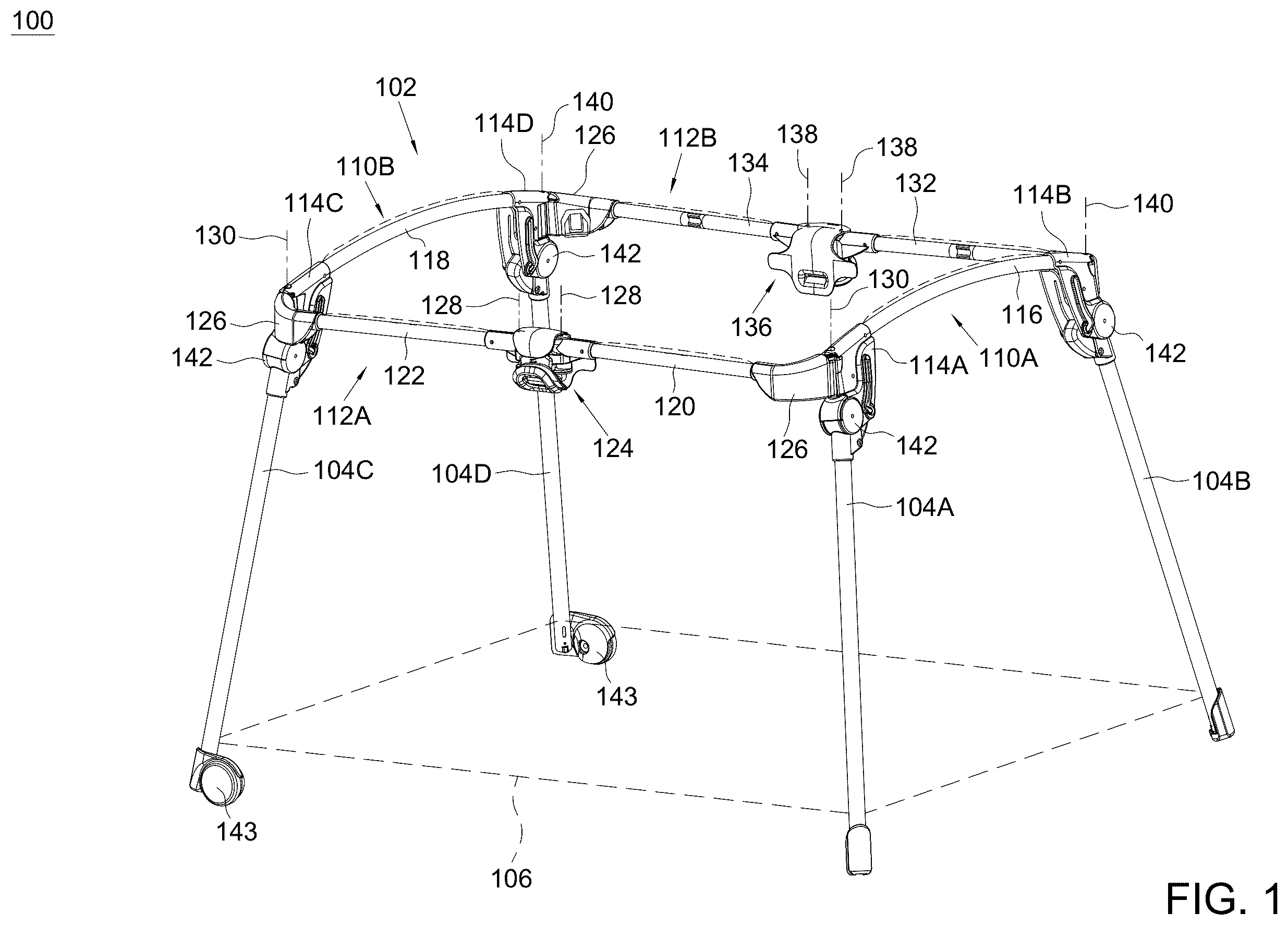
is a perspective view illustrating an embodiment of a playpen;
is a top view of the playpen;
is an enlarged view illustrating a middle joining part of a side frame portion in the playpen;
is a perspective view illustrating construction details of a locking mechanism assembled with the middle joining part for locking an upper frame assembly of the playpen in an unfolded state;
is a perspective view illustrating a latch of the locking mechanism shown in in an unlocking position;
is a perspective view illustrating a locking mechanism disposed adjacent to a corner joining part for locking a standing leg of the playpen in an unfolded position;
is a side view illustrating the locking mechanism for locking the standing leg in the unfolded position;
is a schematic view illustrating another construction of a locking mechanism disposed adjacent to a corner joining part for locking a standing leg in the unfolded position;
are schematic views illustrating exemplary operation of the locking mechanism shown in for folding the standing leg;
is a schematic view illustrating another variant construction of a locking mechanism disposed adjacent to a corner joining part for locking a standing leg in the unfolded position;
is a schematic view illustrating another variant construction of a locking mechanism disposed adjacent to a corner joining part for locking a standing leg in the unfolded position; and
are schematic views illustrating exemplary operation of the locking mechanism shown in for folding the standing leg.
DETAILED DESCRIPTION OF THE EMBODIMENTS
is a schematic view illustrating an embodiment of a playpen 100 , and is a top view of the playpen 100 . Referring to , the playpen 100 can include an upper frame assembly 102 , and a plurality of standing legs 104 A, 104 B, 104 C and 104 D. The upper frame assembly 102 can be coupled with upper end portions of the standing legs 104 A, 104 B, 104 C and 104 D. An enclosure 106 (shown with phantom lines in ) can be stretched between the standing legs 104 A, 104 B, 104 C and 104 D to surround an inner space of the playpen 100 where a young child can be received. The enclosure 106 can be formed by the assembly of one or more fabric, and can have an upper end secured with the upper frame assembly 102 .
The upper frame assembly 102 can be formed by the assembly of multiple bars defining a closed shape. In one embodiment, the upper frame assembly 102 can include two side frame portions 110 A and 110 B opposite to each other and extending substantially parallel to each other along a first direction, two other side frame portions 112 A and 112 B opposite to each other and extending substantially parallel to each other along a second direction perpendicular to the first direction, and a plurality of corner joining parts 114 A, 114 B, 114 C and 114 D that connect the side frame portions 110 A and 110 B with the side frame portions 112 A and 112 B.
Referring to , the side frame portion 110 A can include a continuous bar 116 having two opposite ends respectively connected fixedly with two corner joining parts 114 A and 114 B. For example, the two opposite ends of the bar 116 can be fixedly attached in two openings respectively provided in the two corner joining parts 114 A and 114 B. Likewise, the side frame portion 110 B can include a continuous bar 118 having two opposite ends respectively connected fixedly with two other corner joining parts 114 C and 114 D. According to an example of construction, each of the corner joining parts 114 A, 114 B, 114 C and 114 D may be integrally formed as a unitary part.
The side frame portion 112 A is disposed between the two side frame portions 110 A and 110 B, and includes two bars 120 and 122 that are respectively connected pivotally with a middle joining part 124 at a middle of the side frame portion 112 A. Moreover, the two bars 120 and 122 can be respectively connected pivotally with the two corner joining parts 114 A and 114 C at two opposite ends of the side frame portion 112 A. For example, each of the two bars 120 and 122 can be respectively connected fixedly with a coupling part 126 having a curved shape that is pivotally connected with the corresponding corner joining part 114 A or 114 C. The two bars 120 and 122 can be respectively connected pivotally with the middle joining part 124 about two generally parallel pivot axes 128 , and the two coupling parts 126 of the bars 120 and 122 can be respectively connected pivotally with the two corner joining parts 114 A and 114 C about two generally parallel pivot axes 130 . The pivot axes 128 and 130 can extend substantially vertically when the playpen 100 stands on a floor surface.
The side frame portion 112 B is disposed between the two side frame portions 110 A and 110 B opposite to the side frame portion 112 A, and likewise includes two bars 132 and 134 that are respectively connected pivotally with a middle joining part 136 at a middle of the side frame portion 112 B. The two bars 132 and 134 can be respectively connected pivotally with the two other corner joining parts 114 B and 114 D at two opposite ends of the side frame portion 112 B, e.g., via two coupling parts 126 like described previously. The two bars 132 and 134 can be respectively connected pivotally with the middle joining part 136 about two generally parallel pivot axes 138 , and the two coupling parts 126 of the bars 132 and 134 can be respectively connected pivotally with the two corner joining parts 114 B and 114 D about two generally parallel pivot axes 140 . The pivot axes 138 and 140 can extend substantially vertically when the playpen 100 stands on a floor surface.
The upper frame assembly 102 can thus have two sides defined by the two side frame portions 110 A and 110 B that are not foldable, and two sides defined by the two side frame portions 112 A and 112 B that are foldable. The two middle joining parts 124 and 136 of the side frame portions 112 A and 112 B can move toward each other for folding the upper frame assembly 102 and away from each other for unfolding the upper frame assembly 102 . When the upper frame assembly 102 is in the unfolded state as shown in , the two side frame portions 112 A and 112 B can be generally parallel to each other with the two middle joining parts 124 and 136 spaced apart from each other by a distance, the side frame portions 112 A and 112 B being longer than the side frame portions 110 A and 110 B, i.e., the side frame portions 112 A and 112 B respectively define two longer sides of the playpen 100 and the side frame portions 110 A and 110 B respectively define two shorter sides of the playpen 100 . When the upper frame assembly 102 is in the folded state, the two side frame portions 112 A and 112 B are folded about the two middle joining parts 124 and 136 which are displaced closer to each other, thereby reducing a distance between the two side frame portions 110 A and 110 B.
Referring again to , the standing legs 104 A, 104 B, 104 C and 104 D can be respectively connected pivotally with the corner joining parts 114 A, 114 B, 114 C and 114 D via a plurality of pivot connections 142 . The standing legs 104 C and 104 D may respectively have wheels 143 for facilitating transport of the playpen 100 . Each of the standing legs 104 A, 104 B, 104 C and 104 D can rotate independently relative to the corner joining part 114 A, 114 B, 114 C and 114 D between an unfolded position where the standing leg is deployed for providing standing support on a floor surface (as shown in ) and a folded position where the standing leg is folded toward the upper frame assembly 102 . More specifically, each of the standing legs 104 A and 104 B can project downward from the side frame portion 110 A for providing standing support in the unfolded position, and can be folded toward the side frame portion 110 A in the folded position. Likewise, each of the standing legs 104 C and 104 D can project downward from the side frame portion 110 B for providing standing support in the unfolded position, and can be folded toward the side frame portion 110 B in the folded position. The standing legs 104 A, 104 B, 104 C and 104 D may be folded and unfolded while the upper frame assembly 102 remains in the folded or unfolded state.
With the aforementioned construction, the playpen 100 can have two independent folding configurations: a first folding configuration can reduce a distance between the two side frame portions 110 A and 110 B by folding the upper frame assembly 102 about the two middle joining parts 124 and 136 , and a second folding configuration can reduce a height of the playpen 100 by folding the standing legs 104 A, 104 B, 104 C and 104 D. When only the upper frame assembly 102 is folded while the standing legs 104 A, 104 B, 104 C and 104 D remain unfolded, the playpen 100 may be able to stand upright on the standing legs 104 A, 104 B, 104 C. This may facilitate transport of the playpen 100 , e.g., from one room to another inside a house. For a more compact storage, the standing legs 104 A, 104 B, 104 C and 104 D can further be folded toward the side frame portions 110 A and 110 B at the shorter sides of the upper frame assembly 102 .
In conjunction with , is an enlarged view illustrating the middle joining part 124 of the side frame portion 112 A, and is a perspective view illustrating a locking mechanism 144 assembled with the middle joining part 124 for locking the upper frame assembly 102 in the unfolded state. Referring to , the locking mechanism 144 can include a latch 146 and a spring 148 assembled with the middle joining part 124 . According to an example of construction, the middle joining part 124 can include a bracket 150 and a housing 152 fixedly connected with each other, and the latch 146 can be movably connected with the housing 152 . The latch 146 is movable between a locking position where the latch 146 can engage with the two bars 120 and 122 of the side frame portion 112 A for locking the upper frame assembly 102 in the unfolded state, and an unlocking position where the latch 146 can disengage from the two bars 120 and 122 for adjustment of the upper frame assembly 102 between the unfolded state and the folded state.
According to an exemplary embodiment, the two bars 120 and 122 can respectively have two end coupling parts 154 and 156 that are fixedly attached to the respective ends of the bars 120 and 122 and respectively have extensions 154 A and 156 A for engagement with the latch 146 . The extensions 154 A and 156 A are respectively connected fixedly with the end coupling parts 154 and 156 , e.g., the end coupling part 154 and the extension 154 A may be formed integrally as a single part, and the end coupling part 156 and the extension 156 A may be formed integrally as a single part. The end coupling parts 154 and 156 can be respectively connected pivotally with the bracket 150 of the middle joining part 124 about the two pivot axes 128 so that the end coupling parts 154 and 156 are respectively rotatable along with the bars 120 and 122 about the pivot axes 128 , and the extensions 154 A and 156 A can extend into a gap between the two pivot axes 128 .
The latch 146 can have a locking portion 146 A disposed in the gap between the pivot axes 128 , and is movable to engage and disengage the locking portion 146 A with respect to the extensions 154 A and 156 A of the end coupling parts 154 and 156 . More specifically, the locking portion 146 A of the latch 146 can engage with the extensions 154 A and 156 A in the locking position, and disengage from the extensions 154 A and 156 A in the unlocking position. According to an example of construction, the latch 146 may be slidably assembled with the middle joining part 124 , and can slide in a first direction to engage with the extensions 154 A and 156 A and in a second direction opposite to the first direction to disengage from the extensions 154 A and 156 A. illustrates the latch 146 in the locking position, and illustrates the latch 146 in the unlocking position.
Referring to , the spring 148 is respectively connected with the latch 146 and the middle joining part 124 , and is configured to bias the latch 146 toward the locking position. For example, the spring 148 can have two opposite ends respectively connected with the middle joining part 124 and the locking portion 146 A of the latch 146 .
Referring to , the latch 146 may further have an actuating portion 146 B exposed through the housing 152 of the middle joining part 124 for operation. According to an example of construction, the latch 146 and the actuating portion 146 B can be formed integrally as a single part. A caregiver can press the actuating portion 146 B to cause the latch 146 to move against the biasing force of the spring 148 from the locking position to the unlocking position.
According to an embodiment, the same locking mechanism 144 described previously may be provided in the middle joining part 136 of the side frame portion 112 B for locking the upper frame assembly 102 in the unfolded state.
In conjunction with , are respectively a perspective and a side view illustrating a locking mechanism 158 disposed adjacent to the corner joining part 114 B for locking the standing leg 104 B in the unfolded position. Referring to , the locking mechanism 158 can include a latch 160 and a spring 162 (shown with phantom lines in ). The latch 160 is movably connected with the standing leg 104 B, and is operable to lock the standing leg 104 B in the unfolded position and to unlock the standing leg 104 B for rotation of the standing leg 104 B between the unfolded position and the folded position.
According to an example of construction, the corner joining part 114 B can include a cavity 164 delimited at least partially between two opposite sidewalls 166 of the corner joining part 114 B, and a locking slot portion 168 and a channel 170 symmetrically provided on the two sidewalls 166 . The locking slot portion 168 is connected with the channel 170 , and forms a bend from the channel 170 . The latch 160 can engage with the locking slot portion 168 to lock the standing leg 104 B in the unfolded position, and can disengage from the locking slot portion 168 for rotation of the standing leg 104 B between the unfolded position and the folded position. For example, the latch 160 is fixedly connected with a pin 172 , and is movable relative to the standing leg 104 B to engage and disengage the pin 172 with respect to the locking slot portion 168 . The standing leg 104 B can be locked in the unfolded position when the pin 172 is engaged with the locking slot portion 168 and unlocked when the pin 172 is disengaged from the locking slot portion 168 . According to an example of construction, the latch 160 can be pivotally connected with the standing leg 104 B, whereby the latch 160 can rotate relative to the standing leg 104 B to engage with and disengage from the locking slot portion 168 .
Once the latch 160 is disengaged from the locking slot portion 168 , the latch 160 is movable along with the standing leg 104 B during rotation of the standing leg 104 B relative to the corner joining part 114 B. For example, the pin 172 of the latch 160 can enter the channel 170 when the latch 160 is disengaged from the locking slot portion 168 , and can then slide along the channel 170 during rotation of the standing leg 104 B between the unfolded position and the folded position. The pin 172 can slide along the channel 170 toward an end 170 A of the channel 170 opposite to the locking slot portion 168 when the standing leg 104 B is folded toward the upper frame assembly 102 , and can slide along the channel 170 toward the locking slot portion 168 when the standing leg 104 B is unfolded for use. The latch 160 can be at least partially received in the cavity 164 of the corner joining part 114 B during rotation of the standing leg 104 B.
Referring to , the spring 162 can be respectively connected with the latch 160 and the standing leg 104 B. The spring 162 can bias the latch 160 toward a locking position where the pin 172 is engaged with the locking slot portion 168 for locking the standing leg 104 B in the unfolded position. According to an example of construction, the spring 162 may be a torsion spring assembled around the pivot connection of the latch 160 .
According to an example of construction, the latch 160 can have an actuating portion 160 A exposed for operation. The actuating portion 160 A may be formed integrally with the latch 160 . A caregiver can press the actuating portion 160 A to cause the latch 160 to move to the unlocking position and disengage from the locking slot portion 168 for unlocking the standing leg 104 B.
is a schematic view illustrating another construction of a locking mechanism 258 disposed adjacent to the corner joining part 114 B for locking the standing leg 104 B in the unfolded position. Referring to , the standing leg 104 B can be pivotally connected with the corner joining part 114 B like previously described, and the locking mechanism 258 can include a latch 260 and a spring 262 (shown with phantom lines). The latch 260 can be pivotally connected with the standing leg 104 B via a pivot connection 264 , and can rotate relative to the standing leg 104 B and the corner joining part 114 B to engage and disengage a locking slot portion 268 (shown with phantom lines) provided inside the corner joining part 114 B. For example, the locking slot portion 268 can be at least partially delimited by a sidewall 270 , and the latch 260 can have a protrusion 260 A that engages through the locking slot portion 268 and contacts with the sidewall 270 to prevent a folding rotation of the standing leg 104 B, which can be thereby locked in the unfolded position. The protrusion 260 A can be provided on the latch 260 distant from the pivot connection 264 .
The spring 262 can be respectively connected with the latch 260 and the standing leg 104 B, and can bias the latch 260 toward a locking position engaged with the locking slot portion 268 . According to an example of construction, the spring 262 may have one end connected with the standing leg 104 B and another end connected with the latch 260 at a location adjacent to the protrusion 260 A, as shown in . According to another example of construction, the spring 262 may be replaced with a torsion spring assembled around the pivot connection 264 .
Referring to , the latch 260 can have an actuating portion 260 B exposed for operation. The actuating portion 260 B may be formed integrally with the latch 260 , or fixedly fastened to the latch 260 . According to an example of construction, the latch 260 may have a generally L-shape, and the protrusion 260 A and the actuating portion 260 B can be respectively located adjacent to two opposite ends of the latch 260 . Referring to , a caregiver can press the actuating portion 260 B to cause the latch 160 to rotate and disengage the protrusion 260 A from the locking slot portion 268 for unlocking the standing leg 104 B. Once the latch 260 is disengaged from the locking slot portion 268 , the latch 260 is movable along with the standing leg 104 B during rotation of the standing leg 104 B relative to the corner joining part 114 B.
is a schematic view illustrating another variant construction of a locking mechanism 358 disposed adjacent to the corner joining part 114 B for locking the standing leg 104 B in the unfolded position. Referring to , the locking mechanism 358 can include a latch 360 and a spring 362 (shown with phantom lines). The latch 360 can be slidably connected with the standing leg 104 B, and can slide along the standing leg 104 B to engage with and disengage from a locking slot portion 368 (shown with phantom lines) provided in the corner joining part 114 B. For example, the latch 360 can slide upward relative to the standing leg 104 B to engage a rib 360 A of the latch 360 with the locking slot portion 368 for locking the standing leg 104 B in the unfolded state, and can slide downward relative to the standing leg 104 B to disengage from the locking slot portion 368 for unlocking the standing leg 104 B.
The spring 362 can be respectively connected with the latch 360 and the standing leg 104 B. The spring 362 can bias the latch 360 toward the locking position engaged with the locking slot portion 368 .
Referring to , the latch 360 can have an actuating portion 360 B exposed for operation. According to an example of construction, the actuating portion 360 B may be formed integrally with the latch 360 . A caregiver can press the actuating portion 360 B to cause the latch 360 to move to the unlocking position and disengage from the locking slot portion 368 for unlocking the standing leg 104 B. Once the latch 360 is disengaged from the locking slot portion 368 , the latch 360 is movable along with the standing leg 104 B during rotation of the standing leg 104 B relative to the corner joining part 114 B.
is schematic view illustrating another construction of a locking mechanism 458 disposed adjacent to the corner joining part 114 B for locking the standing leg 104 B in the unfolded position. Referring to , the locking mechanism 458 can include a latch 460 , a linking part 462 and a spring 464 (shown with phantom lines).
The latch 460 can be pivotally connected with the standing leg 104 B via a pivot connection 466 , and the linking part 462 can be respectively connected pivotally with the latch 460 and the corner joining part 114 B via two pivot connections 468 and 470 . Each of the pivot connections 466 , 468 and 470 may exemplary include a shaft portion disposed through corresponding holes provided in the pivotally coupled elements. This assembly can rotationally couple the standing leg 104 B, the latch 460 and the linking part 462 , wherein the latch 460 and the linking part 462 can rotate relative to each other and relative to the standing leg 104 B and the corner joining part 114 B during rotation of the standing leg 104 B relative to the corner joining part 114 B. Moreover, each of the latch 460 and the linking part 462 can have a stop surface that is radially distant from the pivot axis of the pivot connection 468 , i.e., stop surface 474 for the latch 460 and stop surface 476 for the linking part 462 . The stop surface 474 may be provided on a protrusion of the latch 460 , and may move away or toward the stop surface 476 of the linking part 462 depending on the direction of rotation of the latch 460 .
Referring to , the spring 464 can be connected with the latch 460 , and can bias the latch 460 to rotate for protruding outside the corner joining part 114 B, which corresponds to a direction of rotation that moves the stop surface 474 of the latch 460 and the stop surface 476 of the linking part 462 toward each other. According to an example of construction, the spring 464 may be a torsion spring assembled around the pivot connection 466 .
When the standing leg 104 B is in the unfolded state, the pivot connections 466 , 468 and 470 can respectively define three distinct apexes of a triangle, and the stop surface 474 of the latch 460 can contact with the stop surface 476 of the linking part 462 . Moreover, the biasing force applied by the spring 464 can keep the apex of the pivot connection 468 offset from a line joining the respective apexes of the pivot connections 466 and 470 . The standing leg 104 B can be thereby locked in the unfolded position, and the latch 460 can have an actuating portion 460 A exposed in the unfolded position.
Referring to , for folding the standing leg 104 B, a caregiver can press the actuating portion 460 A so that the latch 460 rotates toward an interior of the corner joining part 114 B, which causes the stop surface 474 of the latch 460 to move away from the stop surface 476 of the linking part 462 . The standing leg 104 B can be thereby unlocked, and can then rotate in the folding direction. During rotation of the standing leg 104 B, the latch 460 and the linking part 462 can move along with the standing leg 104 B. Once the standing leg 104 B is fully folded, the latch 460 and the linking part 462 can be entirely received inside the corner joining part 114 B.
When the standing leg 104 B is to be deployed, the standing leg 104 B can be rotated in the unfolding direction, which causes the stop surface 474 of the latch 460 to move toward the stop surface 476 of the linking part 462 . Once the standing leg 104 B reaches the unfolded position, the stop surface 474 of the latch 460 can contact with the stop surface 476 of the linking part 462 , which can lock the standing leg 104 B in the unfolded position.
Since each of the standing legs 104 A, 104 B, 104 C and 104 D of the playpen 100 shown in is folded and unfolded independently, any of the locking mechanisms 158 , 258 , 358 and 458 described herein can be provided adjacent to each of the corner joining parts 114 A, 114 B, 114 C and 114 D for locking the corresponding standing leg in the unfolded position.
Advantages of the structures described herein include the ability to provide a playpen that can independently fold and unfold standing legs, and have multiple folding configurations that may be set independently from one another, which can offer more flexibility for convenient transport and storage of the playpen. Moreover, because the playpen described herein has no bottom linkage, the weight of the playpen can be advantageously reduced.
Realization of the playpen has been described in the context of particular embodiments. These embodiments are meant to be illustrative and not limiting. Many variations, modifications, additions, and improvements are possible. These and other variations, modifications, additions, and improvements may fall within the scope of the inventions as defined in the claims that follow.
Figures (14)
Citations
This patent cites (37)
- US2132988
- US4376318
- US4491992
- US5241716
- US5593046
- US5881789
- US5937457
- US5991944
- US6363550
- US7748798
- US2008/0127412
- US2009/0289473
- US2012/0248394
- US2013/0047335
- US2013/0074257
- US2013/0240815
- US2013/0326808
- US2014/0061563
- US2014/0075670
- US2016/0183698
- US2016/0270557
- US2016/0309914
- US2017/0065100
- US2017/0172311
- US2017/0290444
- US2018/0008056
- US2018/0146796
- US2018/0168365
- US2018/0220809
- US2019/0142183
- US2019/0350378
- US2020/0352342
- US2024/0090682
- USH05338539
- USH11290135
- US2005287835
- US2008154752