Abstract
A hinge mounted cabinet capable of being broken down into multiple sections to reduce the height, width, and length of the disassembled cabinet for shipping.
Claims (1)
1. A cabinet that is mountable to hinges having hinge pins used to hang a door hung in a door jam so that said cabinet can be pivoted upon the hinge pins independently of the door, said cabinet comprising: a main body having an interior side panel having an interior surface and an exterior surface, an exterior side panel having an interior surface and an exterior surface and a rear panel having an interior surface and an exterior surface; said main body having a top section and a bottom section each having an open storage area for placing one or more shelves that extend across the cabinet from the interior side panel to the exterior side panel; said top section and said bottom section being attached to each other by a locking shelf wherein the locking shelf comprises a horizontal panel having a front vertical plate located on a front edge of the horizontal panel and a back vertical plate located on a rear edge of the horizontal panel; and a top dado and a bottom dado located between the back vertical plate and the horizontal panel; said locking shelf having top screw holes and bottom screw holes located on each end of the horizontal panel.
Full Description
Show full text →
FIELD OF THE INVENTION
This invention relates to storage devices and, more particularly, to a cabinet that is mountable to one or more existing hinges and hinge pins of a door.
BACKGROUND OF THE INVENTION
Additional storage has always been a desirable commodity in homes and other structures where space is at a premium. One overlooked area in the past has been the space located behind doors. Storage devices have been developed in the past that hang over the upper edge of doors on hooks and/or attach directly to a rear surface of a door with screws, bolts and/or adhesives. However, these devices may damage the door's finish, damage the structural integrity of the door and/or make it difficult for the door to close by interfering with the door jam.
An additional problem with conventional door mounted cabinets is the size and weight of the devices, which make shipping and transportation expensive costs to end users.
Therefore, a need exists for a hinge mounted cabinet that is mountable to one or more existing hinges and hinge pins of a door wherein the cabinet may be broken down into a compact configuration for shipping.
SUMMARY OF THE INVENTION
The primary object of the present invention is to provide a hinge mounted cabinet that is capable of being broken down into multiple disassembled pieces to reduce the height, width, and length of the disassembled cabinet for shipping.
The present invention fulfills the above and other objects by providing a cabinet that is split into a top section and a bottom section that are secured together using plurality of internal support channels that are locked together using a locking shelf that also provides a shelf surface within the cabinet when assembled.
One or more wall anchors may also be provided with the cabinet to allow the cabinet to be mounted to a wall, rather than hinges. The wall anchor provides at least one doughnut-shaped positioning spacer having a top lip or plate that allows the spacer to be seated in one or more pilot holes drilled into a wall. Toggle bolts may then be placed through the spacers, which hold the toggle bolts in a fixed and centered position in the pilot holes.
The above and other objects, features and advantages of the present invention should become even more readily apparent to those skilled in the art upon a reading of the following detailed description in conjunction with the drawings wherein there is shown and described illustrative embodiments of the invention.
BRIEF DESCRIPTION OF THE DRAWINGS
In the following detailed description, reference will be made to the attached drawings in which:
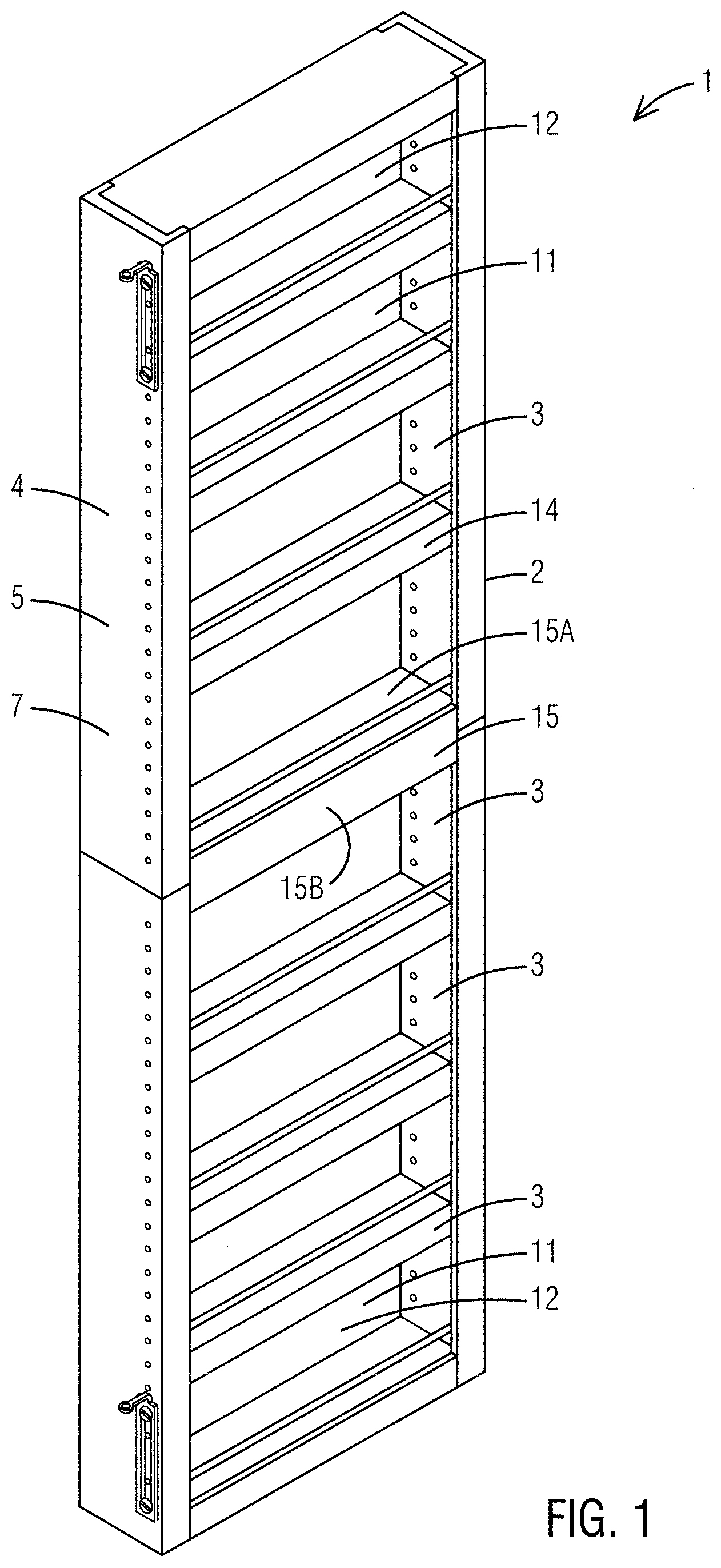
is a perspective interior side view of an assembled cabinet of the present invention;
A- 2 C are perspective exploded views of cabinet of the present invention showing a top section and a bottom section thereof being secured together using a locking shelf of the present invention;
is a sectional view of a locking shelf along lines 3 - 3 of A ; and
is a perspective exploded view of a wall anchor of the present invention.
is a perspective side view of a hinge hanging bracket of the cabinet of the present invention;
is a top view of a hinge hanging bracket of the cabinet of the present invention;
A is a front plan view of a cabinet of the present invention being installed on a wall instead of a pair of hinges; and
B is a front view of a wall hanging bracket of the present invention.
DESCRIPTION OF THE PREFERRED EMBODIMENTS
For purposes of describing the preferred embodiment, the terminology used in reference to the numbered components in the drawings is as follows:
•
• 1 . cabinet, generally • 2 . main body • 2 A. top section of main body • 2 B. bottom section of main body • 3 . interior surface of cabinet • 4 . exterior surface of cabinet • 5 . interior side panel of main body • 6 . interior surface of interior side panel • 7 . exterior surface of interior side panel • 8 . exterior side panel of main body • 9 . interior surface of exterior side panel • 10 . exterior surface of exterior side panel • 11 . rear panel • 12 . interior surface of rear panel • 13 . exterior surface of rear panel • 14 . shelf • 15 . locking shelf • 15 A. horizontal panel • 15 B. front vertical plate • 15 C. back vertical plate • 15 D. top dado • 15 E. bottom dado • 15 F. top screw hole • 15 G. bottom screw hole • 16 . wall anchor • 16 A. plate • 16 B. tubular-shaped spacer • 16 C. toggle bolt • 17 . hinge hanging bracket • 18 . rectangular plate • 19 . top of rectangular plate • 20 . bottom of rectangular plate • 21 . side of rectangular plate • 22 . aperture on rectangular plate • 23 . arm • 24 . proximal end of arm • 25 . distal end of arm • 26 . ring • 27 . ring aperture • 28 . wall hanging bracket • 29 . bolt • 30 . wall • 31 . wall hanging bracket aperture
With reference to , the cabinet 1 of the present invention comprises a top section 2 A and a bottom section 2 B, each having an interior surface 3 and an exterior surface 4 , an interior side panel 5 having an interior surface 6 and an exterior surface 7 , an exterior side panel 8 having an interior surface 9 and an exterior surface 10 and a rear panel 11 having an interior surface 12 and an exterior surface 13 . The top section 2 A and a bottom section 2 B each house an open storage area for placing one or more shelves 14 that extend across the top section 2 A and bottom section 2 B from the interior side panel 5 to the exterior side panel 8 of each section, respectively. The rear panels 11 may be a flat opaque material, mirrors, pegboard, white boards, chalk boards, cork board, and so forth that fit in dados within the main body 2 .
As illustrated in B , the locking shelf 15 allows a user to easily swap out a top rear panel 11 A and/or a bottom rear panel 11 B by only removing a top exterior side panel 8 A and/or a bottom side exterior panel 8 B while the rest of the main body 2 remains mounted to a pair of hinges. For example, a user may swap out an opaque rear panel 11 with a rear panel that is a mirror.
As illustrated in A-C , the top section 2 A and bottom section 2 B may be attached to each other using a locking shelf 15 wherein the locking shelf 15 comprises an elongated horizontal panel 15 A having a front vertical plate 15 B and back vertical plate 15 C one a front edge and rear edge of the horizontal shelf 15 A, respectively, wherein a top dado 15 D and a bottom dado 15 E are located between the back vertical plate 15 C to allow top and bottom rear panels 11 to be inserted in position on the cabinet 1 , as illustrated in .
In addition, the locking shelf 15 comprises top screw holes 15 F and bottom screw holes 15 G located on each end of the horizontal panel 15 A, wherein the top screw holes 15 F are capable of receiving an attachment means such as screws, bolts, studs, and so forth to secure the locking shelf 15 to the top section 2 A of the cabinet 1 . Likewise, the bottom screw holes 15 G are capable of receiving an attachment means such as screws, bolts, studs, and so forth to secure the locking shelf 15 to the bottom section 2 B of the cabinet 1 .
With reference to , a perspective exploded view of a wall anchor 16 of the present invention is illustrated. One or more wall anchors 16 may also be provided with the cabinet 1 to allow the cabinet 1 to be mounted directly to a wall. The wall anchor 16 provides a plate 16 A having at least one tubular-shaped spacer 16 B extending perpendicularly from the plate 16 A. A toggle bolt 16 C may be placed though the tubular-shaped spacer 16 B so the toggle bole 16 C is supported within a pilot hole drilled in the wall while being installed.
With reference to , a perspective side view of a hinge hanging bracket 17 of the present invention and a perspective top view of a hinge hanging bracket 17 of the present invention, respectively, are illustrated. The hinge hanging bracket 17 comprises a substantially rectangular-shaped plate 18 having a top 19 , bottom 20 , and sides 21 . At least one aperture 22 is located on the substantially rectangular-shaped plate 18 . An arm 23 having a proximal end 24 and distal end 25 extends from the top of the substantially rectangular-shaped plate 18 . A ring 26 and aperture 27 are located on the distal end 25 of the arm 23 . An additional feature of the hinge hanging bracket 17 , is that the arm 23 has a width that is less than a diameter of ring 26 and the distal end 25 of the arm 23 . The width of the arm 23 provides clearance from obstructions, such as hinge plates, molding and so forth, so the hinge hanging bracket 17 can be swung back and forth a full 180 degrees in relation to a closed door and a parallel wall.
With reference to A and 7 B , a front plan view of a cabinet 1 of the present invention being installed on a wall 30 is illustrated. The hinge hanging bracket 17 may also be used with a wall hanging bracket 28 instead of a door hinge. The wall hanging bracket 28 is an L-shaped bracket that attaches to a flat surface, such as a wall 18 or a door face, using screws and/or bolts. A stud or bolt 29 is used to connect the ring 26 and the distal end 25 of the arm 23 to the wall hanging bracket 28 , which has an aperture 31 located thereon for receiving the stud or bolt 29 .
It is to be understood that while a preferred embodiment of the invention is illustrated, it is not to be limited to the specific form or arrangement of parts herein described and shown. It will be apparent to those skilled in the art that various changes may be made without departing from the scope of the invention and the invention is not to be considered limited to what is shown and described in the specification and drawings.
Figures (7)
Citations
This patent cites (11)
- US773161
- US2557630
- US2962334
- US3518728
- US4301636
- US8777339
- US9198324
- US9609947
- US2008/0302279
- US2012/0328392
- US2020/0069048