Optical System, Image Projection Apparatus, and Imaging Apparatus
Abstract
The present disclosure is directed to an optical system internally having an intermediate imaging position that is conjugated to a magnification conjugate point on a magnification side and a reduction conjugate point on a reduction side, respectively, the optical system comprising: a magnification optical system positioned on the magnification side with respect to the intermediate imaging position; and a relay optical system positioned on the reduction side with respect to the intermediate imaging position; the relay optical system including: a first lens group positioned closest to the magnification side; two lens groups positioned on the reduction side with respect to the first lens group; and a negative lens group interposed between the two lens groups, wherein during zooming the negative lens is fixed, while the two lens groups are displaced.
Claims (20)
1. An optical system internally having an intermediate imaging position that is conjugated to a magnification conjugate point on a magnification side and a reduction conjugate point on a reduction side, respectively, the optical system comprising: a magnification optical system positioned on the magnification side with respect to the intermediate imaging position; and a relay optical system positioned on the reduction side with respect to the intermediate imaging position, the relay optical system including: a first lens group positioned closest to the magnification side; two lens groups positioned on the reduction side with respect to the first lens group; a first negative lens group interposed between the two lens groups; and a second negative lens group, wherein the second negative lens group has a negative power smaller than that of the first negative lens group, and wherein during zooming the first negative lens group is fixed, while the two lens groups are displaced.
19. An optical system internally having an intermediate imaging position that is conjugated to a magnification conjugate point on a magnification side and a reduction conjugate point on a reduction side, respectively, the optical system comprising: a magnification optical system positioned on the magnification side with respect to the intermediate imaging position; and a relay optical system positioned on the reduction side with respect to the intermediate imaging position, the relay optical system including: a first lens group positioned closest to the magnification side; two lens groups positioned on the reduction side with respect to the first lens group; and a negative lens group interposed between the two lens groups, wherein the following condition (6) is satisfied: 0.8< Tp/Tr< 1.0 (6) where Tp is a distance from a surface closest to the magnification side within the magnification optical system to the intermediate imaging position, and Tr is a distance from the intermediate imaging position to a surface closest to the reduction side within the relay optical system at a wide-angle end.
20. An optical system internally having an intermediate imaging position at which an intermediate image is formed, the intermediate imaging position being conjugated to a magnification conjugate point on a magnification side and a reduction conjugate point on a reduction side, respectively, the optical system comprising: a magnification optical system having a plurality of lens elements, the magnification optical system being positioned on the magnification side with respect to the intermediate imaging position; and a relay optical system having a plurality of lens elements, the relay optical system being positioned on the reduction side with respect to the intermediate imaging position, the plurality of lens elements of the relay optical system including: a first lens group positioned closest to the magnification side; two lens groups positioned on the reduction side with respect to the first lens group; and a negative lens group interposed between the two lens groups, wherein during zooming the negative lens group is fixed, while the two lens groups are displaced, and wherein the following condition (1) is satisfied: 0.1< fp/fr< 0.5 (1) where fp is a focal length of the magnification optical system, and fr is a focal length of the relay optical system at a wide-angle end.
Show 17 dependent claims
2. The optical system according to claim 1 , wherein the first negative lens group has an aperture.
3. The optical system according to claim 1 , wherein a lens positioned closest to the reduction side within the plurality of lens elements of the magnification optical system is a negative lens.
4. The optical system according to claim 1 , wherein a lens positioned closest to the magnification side within the plurality of lens elements of the relay optical system is a positive lens.
5. The optical system according to claim 1 , wherein the following condition (1) is satisfied: 0.1< fp/fr< 0.5 (1) where fp is a focal length of the magnification optical system, and fr is a focal length of the relay optical system at a wide-angle end.
6. The optical system according to claim 1 , wherein the following condition (2) is satisfied: 100<| fr 1/ fw|< 1000 (2) where fr1 is a focal length of the first lens group, and fw is a focal length of the entire optical system at a wide-angle end.
7. The optical system according to claim 1 , wherein the following condition (3) is satisfied: 5< frn/fw< 50 (3) where frn is a focal length of the first negative lens group, and fw is a focal length of the entire optical system at a wide-angle end.
8. The optical system according to claim 1 , wherein the magnification optical system has a longest air distance among a plurality of air distances within the magnification optical system, and the plurality of lens elements of the magnification optical system includes a magnification optical system front group positioned on the magnification side with respect to the longest air distance and a magnification optical system rear group positioned on the reduction side with respect to the longest air distance, and the optical system satisfies the following conditions (4) and (5): 6.5<| Ts/fw|< 12.0 (4) 3.0<| Tpr/fw|< 8.0 (5) where Ts is the longest air distance within the magnification optical system, fw is a focal length of the entire optical system, and Tpr is a distance from a surface closest to the magnification side within the magnification optical system rear group to the intermediate imaging position.
9. The optical system according to claim 1 , wherein the magnification optical system has a longest air distance among a plurality of air distances within the magnification optical system, and the plurality of lens elements of the magnification optical system includes a magnification optical system front group positioned on the magnification side with respect to the longest air distance and a magnification optical system rear group positioned on the reduction side with respect to the longest air distance, and the optical system satisfies the following condition (7): 7<| fpr/fw|< 12 (7) where fpr is a focal length of the magnification optical system rear group.
10. The optical system according to claim 1 , wherein the magnification optical system has a longest air distance among a plurality of air distances within the magnification optical system, and the plurality of lens elements of the magnification optical system includes a magnification optical system front group positioned on the magnification side with respect to the longest air distance and a magnification optical system rear group positioned on the reduction side with respect to the longest air distance, and the optical system satisfies the following condition (8): 2<| fpf/fw|< 5 (8) where fpf is a focal length of the magnification optical system front group.
11. The optical system according to claim 1 , wherein the plurality of lens elements of the magnification optical system includes a first lens element which is arranged closest to the magnification side within the magnification optical system, and the first lens element has a first lens magnification side aspherical surface facing the magnification side and a first lens reduction side aspherical surface facing the reduction side, and the first lens magnification side surface and the first lens reduction side surface satisfy the following condition (9) within a range above zero (r>0) to an effective diameter: dZ ( r )/ dr> 0 (9) where r is a distance (r>0) from a vertex of a surface as measured along a plane perpendicular to the optical axis of the optical system, and Z(r) is an amount of sag of the surface (assuming that Z=0 at the vertex (r=0), where Z has a sign + for reduction side displacement with respect to the vertex, and a sign − for magnification side displacement).
12. The optical system according to claim 1 , wherein the plurality of lens elements of the magnification optical system includes a first lens element that is arranged closest to the magnification side within the magnification optical system, and the first lens element is made of synthetic resin.
13. The optical system according to claim 1 , wherein among the plurality of lens elements of the magnification optical system and the plurality of lens elements of the relay optical system, all lens elements that satisfy the following condition (10) also satisfy the following condition (11), and one lens element does not satisfy both of the conditions (10) and (11): | ym /( fw ·tan(ω m ))|<3.0 (10) Tg> 300° C. (11) where for each lens element, om is a maximum half angle of view at a wide-angle end, ym is a height at a telephoto end at which the most off-axis main ray passes through a surface of the lens element, and Tg is a glass transition point of a lens material of the lens element.
14. The optical system according to claim 1 , wherein the following condition (12) is satisfied: ω m> 65° (12) where ωm is a maximum half angle of view at a wide-angle end.
15. The optical system according to claim 1 , wherein the plurality of lens elements of the magnification optical system includes a first lens element that is arranged closest to the magnification side within the magnification optical system, and the following condition (13) is satisfied: −1.5<( L 1 R 1+ L 1 R 2)/( L 1 R 2− L 1 R 1)<−0.9 (13) where L1R1 is a radius of curvature at a center of a lens magnification side surface of the first lens element, and L1R2 is a radius of curvature at a center of a lens reduction side surface of the first lens element.
16. An image projection apparatus comprising: the optical system according to claim 1 ; and an image forming element that generates an image to be projected through the optical system onto a screen.
17. An imaging apparatus comprising: the optical system according to claim 1 ; and an imaging element that receives an optical image formed by the optical system to convert the optical image into an electrical image signal.
18. The optical system according to claim 1 , wherein the first lens group has a positive power, and the first lens group and the magnification optical system are fixed during zooming.
Full Description
Show full text →
CROSS-REFERENCE OF RELATED APPLICATIONS
This application is a continuation of International Patent Application No. PCT/JP2020/042935, filed on Nov. 18, 2020, which claims the benefit of Japanese Patent Application No. 2020-032016, filed on Feb. 27, 2020, the contents all of which are incorporated herein by reference.
TECHNICAL FIELD
The present disclosure relates to an optical system that forms an intermediate image. The present disclosure also relates to an image projection apparatus and an imaging apparatus using such an optical system.
BACKGROUND
Intermediate imaging-based optical systems have an advantage of achieving wide-angle projection with a short focal length and a wide screen, while the total length of the optical system tends to be increased, thereby rendering the optical system heavier. When attaching a portion of the optical system to an outside of a hosing of an image projection apparatus body, a moment acting on the center of gravity may cause the optical system to tilt relative to the apparatus body, thereby possibly degrading the optical performance.
In order to reduce a weight of the optical system, it may be conceived that a lens made of a synthetic resin is used in lieu of a lens made of glass. Such a synthetic resin has a smaller specific gravity, a smaller thermal conductivity and a larger coefficient of linear expansion as compared to glass. Thus, the optical system can be lightweight. However if local temperature elevation and thermal deformation take place, some optical aberrations, in particular, chromatic aberration tends to be increased. This tendency is more remarkable in case of high-intensity projection.
Patent Document 1 discloses a wide-angle imaging optical system, wherein the first lens L1a positioned closest to the magnification conjugate point has the largest diameter. The first lens L1a has aspherical double surfaces with quite complicated shapes, hence, it could be imagined to use a synthetic resin lens. However, such complicated aspherical shapes tend to be sensitive to thermal deformation. Therefore, it is expected that optical aberrations may be significantly degraded due to temperature elevation.
PATENT DOCUMENT
•
• [Patent Document 1] JP 2019-174633 A
The present disclosure provides an optical system that can reduce a moment acting on the center of gravity and mitigate thermal effect. The present disclosure also provides an image projection apparatus and an imaging apparatus using such an optical system.
One aspect of the present disclosure is directed to an optical system internally having an intermediate imaging position that is conjugated to a magnification conjugate point on a magnification side and a reduction conjugate point on a reduction side, respectively, the optical system comprising:
•
• a magnification optical system positioned on the magnification side with respect to the intermediate imaging position; and • a relay optical system positioned on the reduction side with respect to the intermediate imaging position; • the relay optical system including:
• a first lens group positioned closest to the magnification side; • two lens groups positioned on the reduction side with respect to the first lens group; and • a negative lens group interposed between the two lens groups, • wherein during zooming the negative lens is fixed, while the two lens groups are displaced.
Further, an image projection apparatus according to the present disclosure includes the above-described optical system and an image forming element that generates an image to be projected through the optical system onto a screen.
Still further, an imaging apparatus according to the present disclosure includes the above-described optical system and an imaging element that receives an optical image formed by the optical system to convert the optical image into an electrical image signal.
The optical system according to the present disclosure can reduce a moment acting on the center of gravity and mitigate thermal effect. Therefore, stable optical performance can be kept in case of high intensity light passing through the lens, for example, high-intensity projection.
BRIEF DESCRIPTION OF THE DRAWINGS
is a layout diagram showing an optical path at a wide-angle end in a zoom lens system of example 1 for an object distance of 1065.7157 mm.
A- 2 C are layout diagrams of the zoom lens system of example 1 for an object distance of 1065.7157 mm.
A- 3 C are longitudinal aberrations diagram of the zoom lens system of example 1 for an object distance of 1065.7157 mm.
is a layout diagram showing an optical path at a wide-angle end in a zoom lens system of example 2 for an object distance of 1065.7157 mm.
A- 5 C are layout diagrams of the zoom lens system of example 2 for an object distance of 1065.7157 mm.
A- 6 C are longitudinal aberrations diagram of the zoom lens system of example 2 for an object distance of 1065.7157 mm.
is a layout diagram showing an optical path at a wide-angle end in a zoom lens system of example 3 for an object distance of 1065.7157 mm.
A- 8 C are layout diagrams of the zoom lens system of example 3 for an object distance of 1065.7157 mm.
A- 9 C are longitudinal aberrations diagram of the zoom lens system of example 3 for an object distance of 1065.7157 mm.
is a layout diagram showing an optical path at a wide-angle end in a zoom lens system of example 4 for an object distance of 1065.7157 mm.
A- 11 C are layout diagrams of the zoom lens system of example 4 for an object distance of 1065.7157 mm.
A- 12 C are longitudinal aberrations diagram of the zoom lens system of example 4 for an object distance of 1065.7157 mm.
is a layout diagram showing an optical path at a wide-angle end in a zoom lens system of example 5 for an object distance of 1065.7157 mm.
A- 14 C are layout diagrams of the zoom lens system of example 5 for an object distance of 1065.7157 mm.
A- 15 C are longitudinal aberrations diagram of the zoom lens system of example 5 for an object distance of 1065.7157 mm.
is a layout diagram showing an optical path at a wide-angle end in a zoom lens system of example 6 for an object distance of 1065.7157 mm.
A- 17 C are layout diagrams of the zoom lens system of example 6 for an object distance of 1065.7157 mm.
A- 18 C are longitudinal aberrations diagram of the zoom lens system of example 6 for an object distance of 1065.7157 mm.
is a block diagram showing an example of an image projection apparatus according to the present disclosure.
is a block diagram showing an example of an imaging apparatus according to the present disclosure.
DESCRIPTION OF EMBODIMENT
Hereinafter, embodiments are described in detail with reference to the drawings as appropriate. However, unnecessarily detailed descriptions may be omitted. For example, detailed descriptions of well-known items or redundant descriptions of substantially the same configurations may be omitted. This is to prevent the following description from being unnecessarily redundant and to facilitate understanding by those skilled in the art.
It should be noted that the applicant provides the accompanying drawings and the following description for those skilled in the art to fully understand the present disclosure, and it is not intended to limit the subject matter described in the claims thereby.
Each example of an optical system according to the present disclosure is described below. In each example, described is an example in which the optical system is used in a projector (an example of an image projection apparatus) that projects onto a screen image light of an original image S obtained by spatially modulating incident light using an image forming element, such as liquid crystal or digital micromirror device (DMD), based on an image signal. In other words, the optical system according to the present disclosure can be used for magnifying the original image S on the image forming element arranged on the reduction side to project the image onto the screen (not shown), which is arranged on an extension line on the magnification side.
Further, the optical system according to the present disclosure can also be used for collecting light emitted from an object located on the extension line on the magnification side to form an optical image of the object on an imaging surface of an imaging element arranged on the reduction side.
First Embodiment
Hereinafter, a first embodiment of the present disclosure is described with reference to to 15 . Here, a zoom lens system is described as an example of the optical system.
, 4 , 7 , 10 , 13 and 16 are layout diagrams each showing an optical path at a wide-angle end in a zoom lens system according to any of examples 1 to 6 for an object distance of 1065.7157 mm. A- 2 C, 5 A- 5 C, 8 A- 8 C, 11 A- 11 C, 14 A- 14 C and 17 A- 17 C are layout drawings of the zoom lens system according to examples 1 to 6 for an object distance of 1065.7157 mm. A, 5 A, 8 A, 11 A, 14 A and 17 A are lens arrangement diagrams at the wide-angle end in the zoom lens system. B, 5 B, 8 B, 11 B, 14 B and 17 B are lens arrangement diagrams at an intermediate position in the zoom lens system. C, 5 C, 8 C, 11 C, 14 C and 17 C are lens arrangement diagrams at a telephoto end in the zoom lens system.
The wide-angle end is defined as the shortest focal length state in which the entire optical system has the shortest focal length fw. The intermediate position is defined as an intermediate focal length state between the wide-angle end and the telephoto end. The telephoto end is defined as the longest focal length state in which the entire optical system has the longest focal length ft. By using the focal length fw at the wide-angle end and the focal length ft at the telephoto end, the focal length fm at the intermediate position can be defined as fm=√(fw×ft) (√: square root).
The zoom lens system according to example 1 includes a magnification optical system Op, a relay optical system Ol and an optical element P. The relay optical system Ol includes a first lens group G 1 to a fourth lens group G 4 . The magnification optical system Op is constituted of a first lens element L 1 to a 12th lens element L 12 , including a surface 1 to a surface 24 (see the numerical examples described later). The relay optical system Ol is constituted of a 13th lens element L 13 to a 25th lens element L 25 , including a surface 25 to a surface 51 . The first lens group G 1 having a positive power is constituted of a 13th lens element L 13 to a 15th lens element L 15 , including a surface 25 to a surface 30 . The second lens group G 2 having a positive power is constituted of a 16th lens element L 16 to an 18th lens element L 18 , including a surface 31 to a surface 36 . The third lens group G 3 having a negative power is constituted of a 19th lens element L 19 to a 22nd lens element L 22 , including a surface 37 to a surface 45 . The fourth lens group G 4 having a positive power is constituted of a 23rd lens element L 23 to a 25th lens element L 25 , including a surface 46 to a surface 51 . The optical element P includes a surface 52 to a surface 53 .
The zoom lens system according to example 2 includes a magnification optical system Op, a relay optical system Ol and an optical element P. The relay optical system Ol includes a first lens group G 1 to a fifth lens group G 5 . The magnification optical system Op is constituted of a first lens element L 1 to a 12th lens element L 12 , including a surface 1 to a surface 24 (see the numerical examples described later). The relay optical system Ol is constituted of a 13th lens element L 13 to a 25th lens element L 25 , including a surface 25 to a surface 51 . The first lens group G 1 having a positive power is constituted of a 13th lens element L 13 to a 15th lens element L 15 , including a surface 25 to a surface 30 . The second lens group G 2 having a positive power is constituted of a 16th lens element L 16 to an 18th lens element L 18 , including a surface 31 to a surface 36 . The third lens group G 3 having a negative power is constituted of a 19th lens element L 19 to a 22nd lens element L 22 , including a surface 37 to a surface 45 . The fourth lens group G 4 having a positive power is constituted of a 23rd lens element L 23 , including a surface 46 to a surface 47 . The fifth lens group G 5 having a positive power is constituted of a 24th lens element L 24 to a 25th lens element L 25 , including a surface 48 to a surface 51 . The optical element P includes a surface 52 to a surface 53 .
The zoom lens system according to example 3 includes a magnification optical system Op, a relay optical system Ol and an optical element P. The relay optical system Ol includes a first lens group G 1 to a sixth lens group G 6 . The magnification optical system Op is constituted of a first lens element L 1 to a 12th lens element L 12 , including a surface 1 to a surface 24 (see the numerical examples described later). The relay optical system Ol is constituted of a 13th lens element L 13 to a 25th lens element L 25 , including a surface 25 to a surface 51 . The first lens group G 1 having a positive power is constituted of a 13th lens element L 13 to a 15th lens element L 15 , including a surface 25 to a surface 30 . The second lens group G 2 having a positive power is constituted of a 16th lens element L 16 to an 18th lens element L 18 , including a surface 31 to a surface 36 . The third lens group G 3 having a negative power is constituted of a 19th lens element L 19 to a 22nd lens element L 22 , including a surface 37 to a surface 45 . The fourth lens group G 4 having a positive power is constituted of a 23rd lens element L 23 , including a surface 46 to a surface 47 . The fifth lens group G 5 having a negative power is constituted of a 24th lens element L 24 , including a surface 48 to a surface 49 . The sixth lens group G 6 having a positive power is constituted of a 25th lens element L 25 , including a surface 50 to a surface 51 . The optical element P includes a surface 52 to a surface 53 .
The zoom lens system according to example 4 includes a magnification optical system Op, a relay optical system Ol and an optical element P. The relay optical system Ol includes a first lens group G 1 to a sixth lens group G 6 . The magnification optical system Op is constituted of a first lens element L 1 to a 12th lens element L 12 , including a surface 1 to a surface 24 (see the numerical examples described later). The relay optical system Ol is constituted of a 13th lens element L 13 to a 25th lens element L 25 , including a surface 25 to a surface 51 . The first lens group G 1 having a positive power is constituted of a 13th lens element L 13 to a 15th lens element L 15 , including a surface 25 to a surface 30 . The second lens group G 2 having a positive power is constituted of a 16th lens element L 16 to a 17th lens element L 17 , including a surface 31 to a surface 34 . The third lens group G 3 having a positive power is constituted of an 18th lens element L 18 , including a surface 35 to a surface 36 . The fourth lens group G 4 having a negative power is constituted of a 19th lens element L 19 to a 22nd lens element L 22 , including a surface 37 to a surface 45 . The fifth lens group G 5 having a positive power is constituted of a 23rd lens element L 23 , including a surface 46 to a surface 47 . The sixth lens group G 6 having a positive power is constituted of a 25th lens element L 25 , including a surface 50 to a surface 51 . The optical element P includes a surface 52 to a surface 53 .
The zoom lens system according to example 5 includes a magnification optical system Op, a relay optical system Ol and an optical element P. The relay optical system Ol includes a first lens group G 1 to an eighth lens group G 8 . The magnification optical system Op is constituted of a first lens element L 1 to a 12th lens element L 12 , including a surface 1 to a surface 24 (see the numerical examples described later). The relay optical system Ol is constituted of a 13th lens element L 13 to a 25th lens element L 25 , including a surface 25 to a surface 51 . The first lens group G 1 having a positive power is constituted of a 13th lens element L 13 to a 15th lens element L 15 , including a surface 25 to a surface 30 . The second lens group G 2 having a positive power is constituted of a 16th lens element L 16 , including a surface 31 to a surface 32 . The third lens group G 3 having a negative power is constituted of to a 17th lens element L 17 , including a surface 33 to a surface 34 . The fourth lens group G 4 having a positive power is constituted of an 18th lens element L 18 , including a surface 35 to a surface 36 . The fifth lens group G 5 having a negative power is constituted of a 19th lens element L 19 to a 22nd lens element L 22 , including a surface 37 to a surface 45 . The sixth lens group G 6 having a positive power is constituted of a 23rd lens element L 23 , including a surface 46 to a surface 47 . The seventh lens group G 7 having a negative power is constituted of a 24th lens element L 24 , including a surface 48 to a surface 49 . The eighth lens group G 8 having a positive power is constituted of a 25th lens element L 25 , including a surface 50 to a surface 51 . The optical element P includes a surface 52 to a surface 53 .
The zoom lens system according to example 6 includes a magnification optical system Op, a relay optical system Ol and an optical element P. The relay optical system Ol includes a first lens group G 1 to a sixth lens group G 6 . The magnification optical system Op is constituted of a first lens element L 1 to a 12th lens element L 12 , including a surface 1 to a surface 24 (see the numerical examples described later). The relay optical system Ol is constituted of a 13th lens element L 13 to a 25th lens element L 25 , including a surface 25 to a surface 51 . The first lens group G 1 having a negative power is constituted of a 13th lens element L 13 to a 15th lens element L 15 , including a surface 25 to a surface 30 . The second lens group G 2 having a positive power is constituted of a 16th lens element L 16 to an 18th lens element L 18 , including a surface 31 to a surface 36 . The third lens group G 3 having a positive power is constituted of a 19th lens element L 19 , including a surface 37 to a surface 38 . The fourth lens group G 4 having a negative power is constituted of an aperture and a 20th lens element L 20 , including a surface 39 to a surface 41 . The fifth lens group G 5 having a negative power is constituted of a 21st lens element L 21 to a 22nd lens element L 22 , including a surface 42 to a surface 45 . The sixth lens group G 6 having a positive power is constituted of a 23rd lens element L 23 to a 25th lens element L 25 , including a surface 46 to a surface 51 . The optical element P includes a surface 52 to a surface 53 .
Polygonal line arrows shown in lower part of each of A, 5 A, 8 A, 11 A, 14 A and 17 A include straight lines obtained by connecting the positions of the first lens group G 1 to any one of the final lens group G 4 , G 5 , G 6 , G 8 , corresponding to each of the states of the wide-angle end, the intermediate position, and the telephoto end ranked in order from the top in the drawing. The wide-angle end and the intermediate position, and the intermediate position and the telephoto end are simply connected by a straight line, which is different from the actual movement of each of the lens groups G 1 to G 8 . The symbols (+) and (−) attached to the reference numerals of the respective lens groups G 1 to G 8 indicate the positive or negative power of each of the lens groups G 1 to G 8 .
The zoom lens systems according to examples 1 to 6 may include a focusing adjustment lens group that adjusts the focus when an object distance is changed, and a field curvature correction lens group that corrects the field curvature aberration after focus adjustment by the focusing adjustment lens group.
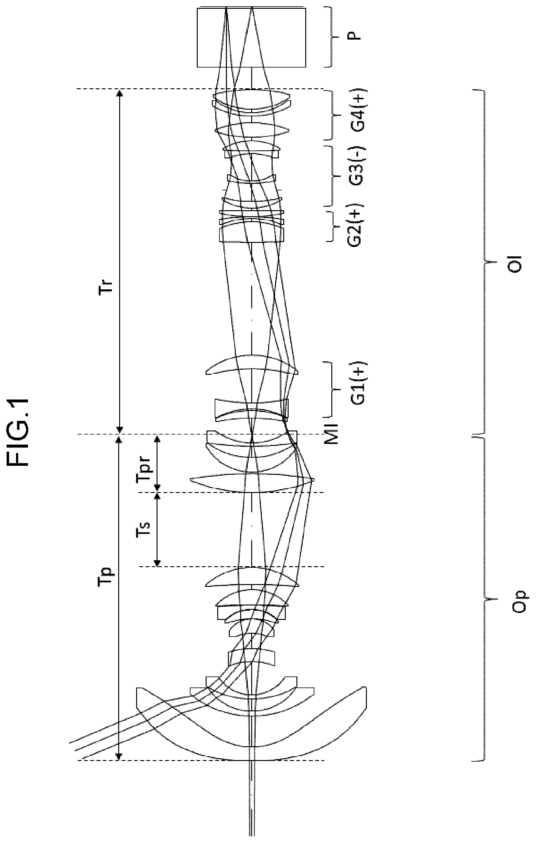
In each of the drawings, an imaging position on the magnification side (i.e., the magnification conjugate point) is located on the left side, and an imaging position on the reduction side (i.e., the reduction conjugate point) is located on the right side. Further, in each of the drawings, the straight line drawn closest to the reduction side represents a position of the original image S, and an optical element P is located on the magnification side of the original image S. The optical element P represents different optical elements, such as a prism for color separation and color synthesis, an optical filter, a flat-parallel glass plate, a crystal low-pass filter, and an infrared cut filter.
The zoom lens system according to each of examples 1 to 6 internally has an intermediate imaging position MI that is conjugated to the magnification conjugate point on the magnification side and the reduction conjugate point on the reduction side, respectively. Further, in each of the drawings, a magnification optical system Op is positioned on the magnification side with respect to the intermediate imaging position MI, and a relay optical system Ol is positioned on the reduction side with respect to the intermediate imaging position MI.
In the zoom lens system according to each of examples 1 to 6, there are a plurality of air distances among the first lens element L 1 to the 25th lens element L 25 and the optical element P. The magnification optical system Op has the longest air distance along an optical axis in the magnification optical system. For example, as shown in A, 5 A, 8 A, 11 A, 14 A and 17 A , there is the longest air distance between the ninth lens element L 9 and the 10th lens element L 10 . The magnification optical system Op includes a magnification optical system front group Opf positioned on the magnification side with respect to the longest air distance and a magnification optical system rear group Opr positioned on the reduction side with respect to the longest air distance. The front group Opf and the rear group Opr may have a single lens element or plural lens elements.
A- 3 C, 6 A- 6 C, 9 A- 9 C, 12 A- 12 C, 15 A- 15 C and 18 A- 18 C are longitudinal aberration diagrams of the zoom lens system according to examples 1 to 6 for an object distance of 1065.7157 mm. A, 6 A, 9 A, 12 A, 15 A and 18 A show longitudinal aberration diagrams at the wide-angle end of the zoom lens system, and B, 6 B, 9 B, 12 B, 15 B and 18 B show longitudinal aberration diagrams at the intermediate position, and C, 6 C, 9 C, 12 C, 15 C and 18 C show longitudinal aberration diagrams at the telephoto end.
Each of the longitudinal aberration diagrams shows spherical aberration (SA (mm)), astigmatism (AST (mm)), and distortion (DIS (%)) in order from the left side. In the spherical aberration diagram, the vertical axis represents a pupil height, and a solid line shows the characteristic of the d-line, a short dashed line shows the characteristic of the F-line, and a long dashed line shows the characteristic of the C-line. In the astigmatism diagram, the vertical axis represents an image height, and a solid line shows the characteristic of the sagittal plane (indicated by s in the drawing), and a dashed line shows the characteristic of the meridional plane (indicated by m in the drawing). In the distortion diagram, the vertical axis represents the image height. The distortion represents distortion with respect to equidistant projection.
Example 1
As shown in A- 2 C , the zoom lens system according to example 1 includes the magnification optical system Op and the relay optical system Ol. The magnification optical system Op is constituted of the first lens element L 1 to the 12th lens element L 12 . The magnification optical system Op includes the front group Opf and the rear group Opr.
The front group Opf of the magnification optical system Op is constituted of the first lens element L 1 to the ninth lens element L 9 in order from the magnification side to the reduction side. The first lens element L 1 has a negative meniscus shape with the convex surfaces facing the magnification side. The second lens element L 2 has a negative meniscus shape with the convex surfaces facing the magnification side. The third lens element L 3 has a negative meniscus shape with the convex surfaces facing the magnification side. The fourth lens element L 4 has a positive meniscus shape with the convex surfaces facing the reduction side. The fifth lens element L 5 has a positive meniscus shape with the convex surfaces facing the reduction side. The sixth lens element L 6 has a positive meniscus shape with the convex surfaces facing the reduction side. The seventh lens element L 7 has a negative meniscus shape with the convex surfaces facing the reduction side. The eighth lens element L 8 has a positive meniscus shape with the convex surfaces facing the reduction side. The ninth lens element L 9 has a positive meniscus shape with the convex surfaces facing the reduction side.
The rear group Opr of the magnification optical system Op is constituted of the 10th lens element L 10 to the 12th lens element L 12 in this order from the magnification side to the reduction side. The 10th lens element L 10 has a biconvex shape.
The 11th lens element L 11 has a positive meniscus shape with the convex surfaces facing the magnification side. The 12th lens element L 12 has a negative meniscus shape with the convex surfaces facing the magnification side.
The relay optical system Ol is constituted of the 13th lens element L 13 to the 25th lens element L 25 in order from the magnification side to the reduction side. The 13th lens element L 13 has a positive meniscus shape with the convex surfaces facing the reduction side. The 14th lens element L 14 has a biconcave shape. The 15th lens element L 15 has a positive meniscus shape with the convex surfaces facing the reduction side. The 16th lens element L 16 has a biconvex shape. The 17th lens element L 17 has a negative meniscus shape with the convex surfaces facing the reduction side. The 18th lens element L 18 has a biconvex shape. The 19th lens element L 19 has a positive meniscus shape with the convex surfaces facing the magnification side. The 20th lens element L 20 has a negative meniscus shape with the convex surfaces facing the magnification side. The 21st lens element L 21 has a biconcave shape. The 22nd lens element L 22 has a biconvex shape. The 23rd lens element L 23 has a biconvex shape. The 24th lens element L 24 has a negative meniscus shape with the convex surfaces facing the magnification side. The 25th lens element L 25 has a biconvex shape.
The relay optical system Ol is constituted of the first lens group (L 13 to L 15 ) having a positive power, the second lens group (L 16 to L 18 ) having a positive power, the third lens group (L 19 to L 22 ) having a negative power, and the fourth lens group (L 23 to L 25 ) having a positive power in order from the magnification side to the reduction side. During zooming the first lens group and the third lens group are fixed, while the second lens group and the fourth lens group are displaced along the optical axis, wherein during from the wide-angle end to the telephoto end, the second lens group and the fourth lens group are displaced toward the magnification side.
In other words, the relay optical system Ol has the first lens group (an example of the “first lens group” in claims) having a positive power positioned closest to the magnification side, the second lens group and the fourth lens group (an example of the “two lens groups” in claims) positioned on the reduction side with respect to the first lens group, and the third lens group (an example of the “negative lens groups” in claims) positioned between the second lens group and the fourth lens group. During zooming the third lens group is fixed, while the second lens group and the fourth lens group are displaced toward the magnification side.
The intermediate imaging position MI is located between the 12th lens element L 12 and the 13th lens element L 13 . Further, an aperture A is arranged between the 19th lens element L 19 and the 20th lens element L 20 . The optical element P having zero optical power is arranged on the reduction side of the relay optical system Ol.
Example 2
As shown in A- 5 C , the zoom lens system according to example 2 includes the magnification optical system Op and the relay optical system Ol. The magnification optical system Op is constituted of the first lens element L 1 to the 12th lens element L 12 . The magnification optical system Op includes the front group Opf and the rear group Opr.
The front group Opf of the magnification optical system Op is constituted of the first lens element L 1 to the ninth lens element L 9 in order from the magnification side to the reduction side. The first lens element L 1 has a negative meniscus shape with the convex surfaces facing the magnification side. The second lens element L 2 has a negative meniscus shape with the convex surfaces facing the magnification side. The third lens element L 3 has a negative meniscus shape with the convex surfaces facing the magnification side. The fourth lens element L 4 has a positive meniscus shape with the convex surfaces facing the reduction side. The fifth lens element L 5 has a positive meniscus shape with the convex surfaces facing the reduction side. The sixth lens element L 6 has a positive meniscus shape with the convex surfaces facing the reduction side. The seventh lens element L 7 has a negative meniscus shape with the convex surfaces facing the reduction side. The eighth lens element L 8 has a positive meniscus shape with the convex surfaces facing the reduction side. The ninth lens element L 9 has a positive meniscus shape with the convex surfaces facing the reduction side.
The rear group Opr of the magnification optical system Op is constituted of the 10th lens element L 10 to the 12th lens element L 12 in this order from the magnification side to the reduction side. The 10th lens element L 10 has a biconvex shape. The 11th lens element L 11 has a positive meniscus shape with the convex surfaces facing the magnification side. The 12th lens element L 12 has a negative meniscus shape with the convex surfaces facing the magnification side.
The relay optical system Ol is constituted of the 13th lens element L 13 to the 25th lens element L 25 in order from the magnification side to the reduction side. The 13th lens element L 13 has a positive meniscus shape with the convex surfaces facing the reduction side. The 14th lens element L 14 has a biconcave shape. The 15th lens element L 15 has a positive meniscus shape with the convex surfaces facing the reduction side. The 16th lens element L 16 has a biconvex shape. The 17th lens element L 17 has a negative meniscus shape with the convex surfaces facing the reduction side. The 18th lens element L 18 has a biconvex shape. The 19th lens element L 19 has a positive meniscus shape with the convex surfaces facing the magnification side. The 20th lens element L 20 has a negative meniscus shape with the convex surfaces facing the magnification side. The 21st lens element L 21 has a biconcave shape. The 22nd lens element L 22 has a biconvex shape. The 23rd lens element L 23 has a biconvex shape. The 24th lens element L 24 has a negative meniscus shape with the convex surfaces facing the magnification side. The 25th lens element L 25 has a biconvex shape.
The relay optical system Ol is constituted of the first lens group (L 13 to L 15 ) having a positive power, the second lens group (L 16 to L 18 ) having a positive power, the third lens group (L 19 to L 22 ) having a negative power, and the fourth lens group (L 23 ) having a positive power in order from the magnification side to the reduction side. During zooming the first lens group and the third lens group are fixed, while the second lens group and the fourth lens group are displaced along the optical axis, wherein during from the wide-angle end to the telephoto end, the second lens group and the fourth lens group are displaced toward the magnification side.
In other words, the relay optical system Ol has the first lens group (an example of the “first lens group” in claims) having a positive power positioned closest to the magnification side, the second lens group and the fourth lens group (an example of the “two lens groups” in claims) positioned on the reduction side with respect to the first lens group, and the third lens group (an example of the “negative lens groups” in claims) positioned between the second lens group and the fourth lens group. During zooming the third lens group is fixed, while the second lens group and the fourth lens group are displaced toward the magnification side.
The intermediate imaging position MI is located between the 12th lens element L 12 and the 13th lens element L 13 . Further, an aperture A is arranged between the 19th lens element L 19 and the 20th lens element L 20 . The optical element P having zero optical power is arranged on the reduction side of the relay optical system Ol.
Example 3
As shown in A- 8 C , the zoom lens system according to example 3 includes the magnification optical system Op and the relay optical system Ol. The magnification optical system Op is constituted of the first lens element L 1 to the 12th lens element L 12 . The magnification optical system Op includes the front group Opf and the rear group Opr.
The front group Opf of the magnification optical system Op is constituted of the first lens element L 1 to the ninth lens element L 9 in order from the magnification side to the reduction side. The first lens element L 1 has a negative meniscus shape with the convex surfaces facing the magnification side. The second lens element L 2 has a negative meniscus shape with the convex surfaces facing the magnification side. The third lens element L 3 has a negative meniscus shape with the convex surfaces facing the magnification side. The fourth lens element L 4 has a positive meniscus shape with the convex surfaces facing the magnification side. The fifth lens element L 5 has a negative meniscus shape with the convex surfaces facing the reduction side. The sixth lens element L 6 has a positive meniscus shape with the convex surfaces facing the reduction side. The seventh lens element L 7 has a negative meniscus shape with the convex surfaces facing the reduction side. The eighth lens element L 8 has a positive meniscus shape with the convex surfaces facing the reduction side. The ninth lens element L 9 has a positive meniscus shape with the convex surfaces facing the reduction side.
The rear group Opr of the magnification optical system Op is constituted of the 10th lens element L 10 to the 12th lens element L 12 in this order from the magnification side to the reduction side. The 10th lens element L 10 has a biconvex shape. The 11th lens element L 11 has a positive meniscus shape with the convex surfaces facing the magnification side. The 12th lens element L 12 has a negative meniscus shape with the convex surfaces facing the magnification side.
The relay optical system Ol is constituted of the 13th lens element L 13 to the 25th lens element L 25 in order from the magnification side to the reduction side. The 13th lens element L 13 has a positive meniscus shape with the convex surfaces facing the reduction side. The 14th lens element L 14 has a biconcave shape. The 15th lens element L 15 has a positive meniscus shape with the convex surfaces facing the reduction side. The 16th lens element L 16 has a biconvex shape. The 17th lens element L 17 has a negative meniscus shape with the convex surfaces facing the reduction side. The 18th lens element L 18 has a biconvex shape. The 19th lens element L 19 has a positive meniscus shape with the convex surfaces facing the magnification side. The 20th lens element L 20 has a negative meniscus shape with the convex surfaces facing the magnification side. The 21st lens element L 21 has a biconcave shape. The 22nd lens element L 22 has a biconvex shape. The 23rd lens element L 23 has a biconvex shape. The 24th lens element L 24 has a negative meniscus shape with the convex surfaces facing the magnification side. The 25th lens element L 25 has a biconvex shape.
The relay optical system Ol is constituted of the first lens group (L 13 to L 15 ) having a positive power, the second lens group (L 16 to L 18 ) having a positive power, the third lens group (L 19 to L 22 ) having a negative power, the fourth lens group (L 23 ) having a positive power, the fifth lens group (L 24 ) having a negative power, and the sixth lens group (L 26 ) having a positive power in order from the magnification side to the reduction side. During zooming the first lens group, the third lens group and the sixth lens group are fixed, while the second lens group, the fourth lens group and the fifth lens group are displaced along the optical axis, wherein during from the wide-angle end to the telephoto end, the second lens group, the fourth lens group and the fifth lens group are displaced toward the magnification side.
In other words, the relay optical system Ol has the first lens group (an example of the “first lens group” in claims) having a positive power positioned closest to the magnification side, the second lens group and the fourth lens group (an example of the “two lens groups” in claims) positioned on the reduction side with respect to the first lens group, and the third lens group (an example of the “negative lens groups” in claims) positioned between the second lens group and the fourth lens group. During zooming the third lens group is fixed, while the second lens group and the fourth lens group are displaced toward the magnification side. The relay optical system Ol further includes the fifth lens group (an example of the “another negative lens groups” in claims), wherein the third lens group has a negative power smaller than that of the fifth lens group.
The intermediate imaging position MI is located between the 12th lens element L 12 and the 13th lens element L 13 . Further, an aperture A is arranged between the 19th lens element L 19 and the 20th lens element L 20 . The optical element P having zero optical power is arranged on the reduction side of the relay optical system Ol.
Example 4
As shown in A- 11 C , the zoom lens system according to example 4 includes the magnification optical system Op and the relay optical system Ol. The magnification optical system Op is constituted of the first lens element L 1 to the 12th lens element L 12 . The magnification optical system Op includes the front group Opf and the rear group Opr.
The front group Opf of the magnification optical system Op is constituted of the first lens element L 1 to the ninth lens element L 9 in order from the magnification side to the reduction side. The first lens element L 1 has a negative meniscus shape with the convex surfaces facing the magnification side. The second lens element L 2 has a negative meniscus shape with the convex surfaces facing the magnification side. The third lens element L 3 has a negative meniscus shape with the convex surfaces facing the magnification side. The fourth lens element L 4 has a positive meniscus shape with the convex surfaces facing the reduction side. The fifth lens element L 5 has a positive meniscus shape with the convex surfaces facing the reduction side. The sixth lens element L 6 has a positive meniscus shape with the convex surfaces facing the reduction side. The seventh lens element L 7 has a biconcave shape. The eighth lens element L 8 has a biconvex shape. The ninth lens element L 9 has a positive meniscus shape with the convex surfaces facing the reduction side.
The rear group Opr of the magnification optical system Op is constituted of the 10th lens element L 10 to the 12th lens element L 12 in this order from the magnification side to the reduction side. The 10th lens element L 10 has a biconvex shape. The 11th lens element L 11 has a positive meniscus shape with the convex surfaces facing the magnification side. The 12th lens element L 12 has a negative meniscus shape with the convex surfaces facing the magnification side.
The relay optical system Ol is constituted of the 13th lens element L 13 to the 25th lens element L 25 in order from the magnification side to the reduction side. The 13th lens element L 13 has a positive meniscus shape with the convex surfaces facing the reduction side. The 14th lens element L 14 has a biconcave shape. The 15th lens element L 15 has a positive meniscus shape with the convex surfaces facing the reduction side. The 16th lens element L 16 has a biconvex shape. The 17th lens element L 17 has a negative meniscus shape with the convex surfaces facing the reduction side. The 18th lens element L 18 has a biconvex shape. The 19th lens element L 19 has a positive meniscus shape with the convex surfaces facing the magnification side. The 20th lens element L 20 has a negative meniscus shape with the convex surfaces facing the magnification side. The 21st lens element L 21 has a biconcave shape. The 22nd lens element L 22 has a biconvex shape. The 23rd lens element L 23 has a biconvex shape. The 24th lens element L 24 has a negative meniscus shape with the convex surfaces facing the magnification side. The 25th lens element L 25 has a biconvex shape.
The relay optical system Ol is constituted of the first lens group (L 13 to L 15 ) having a positive power, the second lens group (L 16 to L 17 ) having a positive power, the third lens group (L 18 ) having a positive power, the fourth lens group (L 19 to L 22 ) having a negative power, the fifth lens group (L 23 ) having a positive power, and the sixth lens group (L 24 to L 25 ) having a positive power in order from the magnification side to the reduction side. During zooming the first lens group, the fourth lens group and the sixth lens group are fixed, while the second lens group, the third lens group and the fifth lens group are displaced along the optical axis, wherein during from the wide-angle end to the telephoto end, the second lens group, the third lens group and the fifth lens group are displaced toward the magnification side.
In other words, the relay optical system Ol has the first lens group (an example of the “first lens group” in claims) having a positive power positioned closest to the magnification side, the third lens group and the fifth lens group (an example of the “two lens groups” in claims) positioned on the reduction side with respect to the first lens group, and the fourth lens group (an example of the “negative lens groups” in claims) positioned between the third lens group and the fifth lens group. During zooming the fourth lens group is fixed, while the third lens group and the fifth lens group are displaced toward the magnification side.
The intermediate imaging position MI is located between the 12th lens element L 12 and the 13th lens element L 13 . Further, an aperture A is arranged between the 19th lens element L 19 and the 20th lens element L 20 . The optical element P having zero optical power is arranged on the reduction side of the relay optical system Ol.
Example 5
As shown in A- 14 C , the zoom lens system according to example 5 includes the magnification optical system Op and the relay optical system Ol. The magnification optical system Op is constituted of the first lens element L 1 to the 12th lens element L 12 . The magnification optical system Op includes the front group Opf and the rear group Opr.
The front group Opf of the magnification optical system Op is constituted of the first lens element L 1 to the ninth lens element L 9 in order from the magnification side to the reduction side. The first lens element L 1 has a negative meniscus shape with the convex surfaces facing the magnification side. The second lens element L 2 has a negative meniscus shape with the convex surfaces facing the magnification side. The third lens element L 3 has a negative meniscus shape with the convex surfaces facing the magnification side. The fourth lens element L 4 has a positive meniscus shape with the convex surfaces facing the reduction side. The fifth lens element L 5 has a positive meniscus shape with the convex surfaces facing the reduction side. The sixth lens element L 6 has a positive meniscus shape with the convex surfaces facing the reduction side. The seventh lens element L 7 has a biconcave shape. The eighth lens element L 8 has a positive meniscus shape with the convex surfaces facing the reduction side. The ninth lens element L 9 has a biconvex shape.
The rear group Opr of the magnification optical system Op is constituted of the 10th lens element L 10 to the 12th lens element L 12 in this order from the magnification side to the reduction side. The 10th lens element L 10 has a biconvex shape. The 11th lens element L 11 has a positive meniscus shape with the convex surfaces facing the magnification side. The 12th lens element L 12 has a negative meniscus shape with the convex surfaces facing the magnification side.
The relay optical system Ol is constituted of the 13th lens element L 13 to the 25th lens element L 25 in order from the magnification side to the reduction side. The 13th lens element L 13 has a positive meniscus shape with the convex surfaces facing the reduction side. The 14th lens element L 14 has a biconcave shape. The 15th lens element L 15 has a positive meniscus shape with the convex surfaces facing the reduction side. The 16th lens element L 16 has a biconvex shape. The 17th lens element L 17 has a negative meniscus shape with the convex surfaces facing the reduction side. The 18th lens element L 18 has a biconvex shape. The 19th lens element L 19 has a positive meniscus shape with the convex surfaces facing the magnification side. The 20th lens element L 20 has a negative meniscus shape with the convex surfaces facing the magnification side. The 21st lens element L 21 has a biconcave shape. The 22nd lens element L 22 has a biconvex shape. The 23rd lens element L 23 has a biconvex shape. The 24th lens element L 24 has a negative meniscus shape with the convex surfaces facing the magnification side. The 25th lens element L 25 has a biconvex shape.
The relay optical system Ol is constituted of the first lens group (L 13 to L 15 ) having a positive power, the second lens group (L 16 ) having a positive power, the third lens group (L 17 ) having a negative power, the fourth lens group (L 18 ) having a positive power, the fifth lens group (L 19 to L 22 ) having a negative power, the sixth lens group (L 23 ) having a positive power, the seventh lens group (L 24 ) having a negative power, and the eighth lens group (L 25 ) having a positive power in order from the magnification side to the reduction side. During zooming the first lens group, the fifth lens group and the eighth lens group are fixed, while the second lens group, the third lens group, the fourth lens group, the sixth lens group and the seventh lens group are displaced along the optical axis, wherein during from the wide-angle end to the telephoto end, the second lens group, the third lens group, the fourth lens group and the sixth lens group and the seventh lens group are displaced toward the magnification side.
In other words, the relay optical system Ol has the first lens group (an example of the “first lens group” in claims) having a positive power positioned closest to the magnification side, the fourth lens group and the sixth lens group (an example of the “two lens groups” in claims) positioned on the reduction side with respect to the first lens group, and the fifth lens group (an example of the “negative lens groups” in claims) positioned between the fourth lens group and the sixth lens group. During zooming the fifth lens group is fixed, while the fourth lens group and the sixth lens group are displaced toward the magnification side. The relay optical system Ol further includes the third lens group and the seventh lens group (an example of the “another negative lens groups” in claims), wherein the fifth lens group has a negative power smaller than those of the third lens group and the seventh lens group.
The intermediate imaging position MI is located between the 12th lens element L 12 and the 13th lens element L 13 . Further, an aperture A is arranged between the 19th lens element L 19 and the 20th lens element L 20 . The optical element P having zero optical power is arranged on the reduction side of the relay optical system Ol.
Example 6
As shown in A- 17 C , the zoom lens system according to example 6 includes the magnification optical system Op and the relay optical system Ol. The magnification optical system Op is constituted of the first lens element L 1 to the 12th lens element L 12 . The magnification optical system Op includes the front group Opf and the rear group Opr.
The front group Opf of the magnification optical system Op is constituted of the first lens element L 1 to the ninth lens element L 9 in order from the magnification side to the reduction side. The first lens element L 1 has a negative meniscus shape with the convex surfaces facing the magnification side. The second lens element L 2 has a negative meniscus shape with the convex surfaces facing the magnification side. The third lens element L 3 has a negative meniscus shape with the convex surfaces facing the magnification side. The fourth lens element L 4 has a positive meniscus shape with the convex surfaces facing the reduction side. The fifth lens element L 5 has a positive meniscus shape with the convex surfaces facing the reduction side. The sixth lens element L 6 has a positive meniscus shape with the convex surfaces facing the reduction side. The seventh lens element L 7 has a biconcave shape. The eighth lens element L 8 has a positive meniscus shape with the convex surfaces facing the reduction side. The ninth lens element L 9 has a biconvex shape.
The rear group Opr of the magnification optical system Op is constituted of the 10th lens element L 10 to the 12th lens element L 12 in this order from the magnification side to the reduction side. The 10th lens element L 10 has a biconvex shape. The 11th lens element L 11 has a positive meniscus shape with the convex surfaces facing the magnification side. The 12th lens element L 12 has a negative meniscus shape with the convex surfaces facing the magnification side.
The relay optical system Ol is constituted of the 13th lens element L 13 to the 25th lens element L 25 in order from the magnification side to the reduction side. The 13th lens element L 13 has a positive meniscus shape with the convex surfaces facing the reduction side. The 14th lens element L 14 has a biconcave shape. The 15th lens element L 15 has a positive meniscus shape with the convex surfaces facing the reduction side. The 16th lens element L 16 has a biconvex shape. The 17th lens element L 17 has a negative meniscus shape with the convex surfaces facing the reduction side. The 18th lens element L 18 has a biconvex shape. The 19th lens element L 19 has a positive meniscus shape with the convex surfaces facing the magnification side. The 20th lens element L 20 has a negative meniscus shape with the convex surfaces facing the magnification side. The 21st lens element L 21 has a biconcave shape. The 22nd lens element L 22 has a biconvex shape. The 23rd lens element L 23 has a biconvex shape. The 24th lens element L 24 has a negative meniscus shape with the convex surfaces facing the magnification side. The 25th lens element L 25 has a biconvex shape.
The relay optical system Ol is constituted of the first lens group (L 13 to L 15 ) having a negative power, the second lens group (L 16 to L 18 ) having a positive power, the third lens group (L 19 ) having a positive power, the fourth lens group (L 20 ) having a negative power, the fifth lens group (L 21 to L 22 ) having a negative power, and the sixth lens group (L 23 to L 25 ) having a positive power in order from the magnification side to the reduction side. During zooming the first lens group and the fourth lens group are fixed, while the second lens group, the third lens group, the fifth lens group and the sixth lens group are displaced along the optical axis, wherein during from the wide-angle end to the telephoto end, the second lens group, the fifth lens group and the sixth lens group displaced toward the magnification side and the third lens group are displaced toward the reduction side.
In other words, the relay optical system Ol has the first lens group (an example of the “first lens group” in claims) having a negative power positioned closest to the magnification side, the third lens group and the fifth lens group (an example of the “two lens groups” in claims) positioned on the reduction side with respect to the first lens group, and the fourth lens group (an example of the “negative lens groups” in claims) positioned between the third lens group and the fifth lens group. During zooming the fourth lens group is fixed, while the third lens group and the fifth lens group are displaced toward the magnification side. The relay optical system Ol further includes the fourth lens group and the fifth lens group (an example of the “another negative lens groups” in claims), wherein the fourth lens group has a negative power smaller than that of the fifth lens group.
The intermediate imaging position MI is located between the 12th lens element L 12 and the 13th lens element L 13 . Further, an aperture A is arranged between the 19th lens element L 19 and the 20th lens element L 20 . The optical element P having zero optical power is arranged on the reduction side of the relay optical system Ol.
The zoom lens system according to each of examples 1 to 6 may include not only lens elements having an optical power but also elements having zero or substantially zero optical power, such as mirrors, apertures, masks, cover glasses, filters, prisms, wave plates, and polarizing elements.
Next, conditions which the zoom lens system according to each of examples 1 to 6 can satisfy are described below. Although a plurality of the conditions are defined for the zoom lens system according to each of the examples, all of these plurality of conditions may be satisfied, or the individual conditions may be satisfied to obtain the corresponding effects.
The zoom lens system according to each of examples 1 to 6 internally has an intermediate imaging position that is conjugated to a magnification conjugate point on a magnification side and a reduction conjugate point on a reduction side, respectively. The zoom lens system includes a magnification optical system positioned on the magnification side with respect to the intermediate imaging position and a relay optical system positioned on the reduction side with respect to the intermediate imaging position. The relay optical system includes a first lens group having a positive power that is positioned closest to the magnification side, two lens groups positioned on the reduction side with respect to the first lens group, and a negative lens group interposed between the two lens groups, wherein during zooming the negative lens is fixed, while the two lens groups are displaced.
According to this configuration, even when the lens is made wider in angle, the lens can be made small in effective diameter and light in weight. Further the zoom actuation mechanism can be made simple, so that mechanical components thereof as well as the entire lens can be made light in weight.
In the zoom lens system according to each of examples 1 to 6, the first lens group and the magnification optical system may be fixed during zooming.
According to this configuration, arrangement of a zoom mechanism closer to the reduction side with respect to the intermediate imaging position allows a zoom operation mechanism, such as, cam, motor, to be implemented on the reduction side. Therefore, the center of gravity of a lens barrel can be brought closer to the reduction side.
Further, in the zoom lens system according to each of examples 1 to 6, the relay optical system may further include an another negative lens group, wherein said negative lens group may have a negative power smaller than that of said another negative lens group.
According to this configuration, during zooming variation in aberration can be made smaller, resulting in good performance over the entire zoom range.
Further, in the zoom lens system according to each of examples 1 to 6, said negative lens group may have an aperture.
According to this configuration, during zooming variation in aberration can be made smaller, resulting in good performance over the entire zoom range.
Further, in the zoom lens system according to each of examples 1 to 6, a lens positioned closest to the reduction side within the magnification optical system may be a negative lens.
According to this configuration, the lens close to the intermediate imaging position can be made small in effective diameter and light in weight.
In the zoom lens system according to each of examples 1 to 6, a lens positioned closest to the magnification side within the relay optical system may be a positive lens.
According to this configuration, the lens close to the intermediate imaging position can be made small in effective diameter and light in weight.
Further, the zoom lens system according to each of examples 1 to 6 may satisfy the following condition (1): 0.1< fp/fr< 0.5 (1)
where fp is a focal length of the magnification optical system, and fr is a focal length of the relay optical system at the wide-angle end.
The condition (4) is a conditional expression for defining the relationship between the composite focal lengths of the magnification optical system and the relay optical system. When satisfying this, an optical system having a wide angle and a small lens diameter can be realized. If falling below the lower limit value of the condition (4), the effective diameter of the positive power lens element which is located on the magnification side with respect to the intermediate imaging position and second-closest to the intermediate imaging position becomes too large, and the lens becomes heavier. On the other hand, if exceeding the upper limit value, the effective diameter of the lens located closest to the magnification side becomes too large, and the lens becomes heavier.
In addition to the condition (1), more advantageous effects can be obtained by further satisfying the following condition (1A): 0.15< fp/fr< 0.30 (1A)
Further, the zoom lens system according to each of examples 1 to 6 may satisfy the following condition (2): 100<| fr 1/ fw|< 1000 (2)
where fr1 is a focal length of the first lens group, and fw is a focal length of the entire optical system at the wide-angle end.
The condition (2) is a conditional expression for defining the relationship between the focal length of the first lens group and the focal length of the entire optical system at the wide-angle end. When satisfying this, an optical system having a wide angle and a small lens diameter can be realized. If exceeding the upper limit of the condition (2), the diameter of the first lens group becomes too large, and the lens becomes heavier accordingly. On the other hand, if falling below the lower limit, the diameter of the rear group of the magnification optical system becomes too large, and the lens becomes heavier accordingly.
In addition to the condition (2), more advantageous effects can be obtained by further satisfying the following condition (2A): 150<| fr 1/ fw|< 700 (2A)
Further, the zoom lens system according to each of examples 1 to 6 may satisfy the following condition (3): 5< frn/fw< 50 (3)
where frn is a focal length of the negative lens group, and fw is a focal length of the entire optical system at the wide-angle end.
The condition (3) is a conditional expression for defining the relationship between the focal length of the negative lens group and the focal length of the entire optical system at the wide-angle end. When satisfying this, an optical system having a wide angle and a small lens diameter can be realized. If exceeding the upper limit of the condition (3), the diameter of the negative lens group becomes too large, and the lens becomes heavier accordingly. On the other hand, if falling below the lower limit, the diameter of the lens group positioned on the reduction side with respect to the negative lens group becomes too large, and the lens becomes heavier accordingly.
In addition to the condition (3), more advantageous effects can be obtained by further satisfying the following condition (3A): 8< frn/fw< 30 (3A)
Further, in the zoom lens system according to each of examples 1 to 6, the magnification optical system may have the longest air distance, and include a magnification optical system front group positioned on the magnification side with respect to the longest air distance and a magnification optical system rear group positioned on the reduction side with respect to the longest air distance, and the zoom lens system may satisfy the following conditions (4) and (5): 6.5<| Ts/fw|< 12.0 (4) 3.0<| Tpr/fw|< 8.0 (5)
where Ts is the longest air distance within the magnification optical system, fw is a focal length of the entire optical system, and Tpr is a distance from a surface closest to the magnification side within the magnification optical system rear group to the intermediate imaging position.
The condition (4) is a conditional expression for defining the relationship between the longest air distance within the magnification optical system and the focal length of the entire optical system at the wide-angle end. When satisfying the condition (4), the optical system can achieve a wider angle. If falling below the lower limit of the condition (4), the lens of the magnification optical system front group becomes heavier. If exceeding the upper limit of the condition (4), the center of gravity of the entire optical system is moved to the magnification side. The condition (5) is a conditional expression for defining the relationship between the distance from the surface on the magnification side within the magnification optical system rear group to the intermediate imaging position and the focal length of the entire optical system at the wide-angle end. When satisfying the condition (5), the effect of the condition (4) can be exhibited.
In addition to the conditions (4) and (5), more advantageous effects can be obtained by further satisfying the following conditions (4A) and (5A): 6.5<| Ts/fw|< 10.0 (4A) 5.0<| Tpr/fw|< 6.5 (5A)
The zoom lens system according to each of examples 1 to 6 may satisfy the following conditional expression (6): 0.8< Tp/Tr< 1.0 (6)
where Tp is a distance from a surface closest to the magnification side within the magnification optical system to the intermediate imaging position, and Tr is a distance from the intermediate imaging position to a surface closest to the reduction side within the relay optical system at the wide-angle end.
The condition (6) is a conditional expression for defining the relationship between the distance from the surface closest to the magnification side within the magnification optical system to the intermediate imaging position and the distance from the intermediate imaging position to the surface closest to the reduction side within the relay optical system at the wide-angle end. If exceeding the upper limit of the condition (6), it becomes difficult to correct the field curvature. If falling below the lower limit of the condition (6), the center of gravity is moved toward the magnification side.
In addition to the condition (6), more advantageous effects can be obtained by further satisfying the following condition (6A): 0.9< Tp/Tr< 1.0 (6A)
In the zoom lens system according to each of examples 1 to 6, the magnification optical system may have the longest air distance, and include a magnification optical system front group positioned on the magnification side with respect to the longest air distance and a magnification optical system rear group positioned on the reduction side with respect to the longest air distance, and the zoom lens system may satisfy the following conditional expression (7): 7<| fpr/fw|< 12 (7)
where fpr is a focal length of the magnification optical system rear group.
The condition (7) is a conditional expression for defining the relationship between the focal length of the magnification optical system rear group and the focal length of the entire optical system at the wide-angle end. If exceeding the upper limit of the condition (7), the diameter of the magnification optical system rear group becomes too large, and the lens becomes heavier accordingly. If falling below the lower limit of the condition (7), the diameter of the magnification optical system front group becomes too large, and the lens becomes heavier accordingly.
In addition to the condition (7), more advantageous effects can be obtained by further satisfying the following condition (7A): 9<| fpr/fw|< 10 (7A)
In the zoom lens system according to each of examples 1 to 6, the magnification optical system may have the longest air distance, and include a magnification optical system front group positioned on the magnification side with respect to the longest air distance and a magnification optical system rear group positioned on the reduction side with respect to the longest air distance, and the zoom lens system may satisfy the following conditional expression (8): 2<| fpf/fw|< 5 (8)
where fpf is a focal length of the magnification optical system front group.
The condition (8) is a conditional expression for defining the relationship between the focal length of the magnification optical system front group and the focal length of the entire optical system at the wide-angle end. If exceeding the upper limit of the condition (8), the diameter of the magnification optical system front group becomes too large, and the lens becomes heavier accordingly. If falling below the lower limit of the condition (8), the diameter of the magnification optical system rear group becomes too large, and the lens becomes heavier accordingly.
In addition to the condition (8), more advantageous effects can be obtained by further satisfying the following condition (8A): 3<| fpf/fw|< 4 (8A)
Further, in the zoom lens system according to each of examples 1 to 6, the first lens element may be arranged closest to the magnification side within the magnification optical system, and the first lens element may have a first lens magnification side aspherical surface facing the magnification side and a first lens reduction side aspherical surface facing the reduction side, and
the first lens magnification side surface and the first lens reduction side surface may satisfy the following condition (9) within a range above zero (r>0) to an effective diameter: dZ ( r )/ dr> 0 (9)
where r is a distance (r>0) from a vertex of a surface as measured along a plane perpendicular to the optical axis of the optical system, and Z(r) is an amount of sag of the surface (assuming that Z=0 at the vertex (r=0), where Z has a sign + for reduction side displacement with respect to the vertex, and a sign − for magnification side displacement).
The condition (14) is a conditional expression for defining that the first derivative dZ(r)/dr of the amount of sag Z(r) of the surface is positive. When satisfying the condition (14), even when local heat is generated in the first lens element, a change in shape due to thermal expansion take places likewise in both the magnification side surface and the reduction side surface of the first lens element. As a result, the occurrence of field curvature and astigmatism can be suppressed.
In addition, in the zoom lens system according to each of examples 1 to 6, the first lens element may be made of synthetic resin.
According to this configuration, the first lens element is easily made large in diameter, and the weight of the lens can be reduced by using the synthetic resin.
In the zoom lens system according to each of examples 1 to 6, all the lens elements that satisfy the condition (10) among the plurality of lens elements may satisfy the condition (11), and one lens element among the plurality of lens elements may not satisfy both of the conditions (10) and (11): | ym /( fw ·tan(ω m ))|<3.0 (10) Tg> 300° C. (11)
where ωm is a maximum half angle of view at the wide-angle end, ym is a height at the telephoto end at which the most off-axis main ray passes through the lens surface, and Tg is a glass transition point of lens material.
The condition (10) is a conditional expression for defining the relationship among the height at the telephoto end at which the most off-axis main ray passes through the lens surface, the focal length of the entire optical system at the wide-angle end, and the maximum half angle of view at the wide-angle end. The condition (11) is a conditional expression for defining the glass transition point of the lens material. When satisfying both of the conditions (10) and (11), deterioration of the lens can be prevented when high intensity light passes through the lens. Note that ym is calculated as a lower one out of a height of the light passing through the surface on the magnification side and a height of the light passing through the surface on the reduction side of the lens. Further, in a case of not satisfying the condition (10), a material not satisfying the glass transition point Tg of the lens material may be selected in order to expand the scope of selection of a glass material that is less susceptible to heat. This allows a material having a low glass transition point Tg, such as resin, to be selected and thus allows reduction in weight.
Further, the zoom lens system according to each of examples 1 to 6 may satisfy the following conditional expression (12): ω m> 65° (12)
where ωm is a maximum half angle of view at the wide-angle end.
The condition (12) is a conditional expression for defining the maximum half angle of view at the wide-angle end. When satisfying the condition (12) is satisfied, a working distance can be shortened.
Further, the zoom lens system according to each of examples 1 to 6 may satisfy the following conditional expression (13): −1.5<( L 1 R 1+ L 1 R 2)/( L 1 R 2− L 1 R 1)<−0.9 (13)
where L1R1 is a radius of curvature at the center of the lens magnification side surface closest to the magnification side, and L1R2 is a radius of curvature at the center of the lens reduction side surface closest to the magnification side.
The condition (13) is a conditional expression for defining the shaping factor of the first lens element positioned closest to the magnification side within the magnification optical system. When satisfying the condition (13), the effective diameter of the lens can be reduced while correcting field curvature and distortion aberration. If falling below the lower limit of the condition (13), field curvature and distortion aberration cannot be sufficiently corrected. Further, if exceeding the upper limit, the effective diameter of the lens positioned on the reduction side becomes larger.
In addition to the condition (13), more advantageous effects can be obtained by further satisfying the following condition (13A): −1.2<( L 1 R 1+ L 1 R 2)/( L 1 R 2− L 1 R 1)<−1.07 (13A)
In the zoom optical system according to each of examples 1 to 6, the group positioned closest to the magnification side within the rear group may have a positive power and may be displaced toward the magnification side during zooming from the wide-angle end to the telephoto end.
According to this configuration, during zooming variation in aberration can be made smaller.
In the zoom optical system according to each of examples 1 to 6, the group positioned adjacent to the front group positioned on the magnification side may have a positive power, and the group positioned adjacent to the reduction side may have a positive power.
According to this configuration, during zooming variation in aberration can be made smaller.
As described above, some examples have been described to exemplify the technology disclosed in the present application. The technology of the present disclosure, however, is not limited only to these examples, but also can be applied to other embodiments appropriately devised through modification, substitution, addition, omission and so on.
Hereinafter, numerical examples of the zoom lens system according to examples 1 to 6 are described. In each of the numerical examples, in the table, the unit of length is all “mm”, and the unit of angle of view is all “°” (degree). Further, in each of the numerical examples, r is a radius of curvature, d is a surface interval, nd is a refractive index for d line, and vd is an Abbe number for d line. Further, in each of the numerical examples, a surface marked with “*” is aspherical, and the aspherical shape is defined by the following formula.
Z = h 2 / r 1 + 1 - ( 1 + κ ) ( h / r ) 2 + ∑ A n h n [ Mathematical Formula 1 ]
where Z is a distance from a point located on an aspherical surface at a height “h” from the optical axis, to the tangent plane of the aspherical vertex, h is a height from the optical axis, r is a radius of curvature of the vertex, κ is a cone constant, and An is a nth-order aspherical coefficient.
Numerical Example 1
Regarding the zoom lens system of numerical example 1 (corresponding to example 1), Table 1 shows surface data, Table 2 shows various data, and Table 3 shows single lens data (unit: mm).
TABLE 1
Surface data
SURFACE NUMBER r d nd vd
Object plane ∞ (infinity)
1* 1559.72740 10.00000 1.50940 56.5
2* 49.93020 21.30460
3 62.81020 3.50000 1.80420 46.5
4 34.70010 8.90130
5 56.73020 2.50000 1.80420 46.5
6 26.07540 23.46460
7 −45.65000 9.58260 1.80420 46.5
8 −43.96980 10.59440
9* −26.79370 9.98320 1.51633 64.1
10* −17.01960 0.20000
11 −48.20740 6.63870 1.49700 81.6
12 −23.22440 0.20000
13 −24.11240 2.50000 1.86966 20.0
14 −390.21520 0.27550
15 −310.33810 10.92670 1.49700 81.6
16 −32.54250 3.54050
17 −327.98450 12.31470 1.49700 81.6
18 −44.92820 52.72720
19 112.99220 12.93660 1.92286 20.9
20 −242.56180 1.07700
21 34.64080 10.20050 1.92286 20.9
22 47.22600 7.87550
23 175.26870 2.64100 1.80420 46.5
24 40.67200 17.69210
25 −99.40430 5.09720 1.73800 32.3
26 −58.46020 1.18700
27 −48.52090 4.00000 1.75500 52.3
28 112.52870 24.31600
29 −103.32630 9.73590 1.86966 20.0
30 −46.35090 variable
31 628.18950 14.57510 1.59282 68.6
32 −52.01000 1.93020
33 −50.20170 1.50000 1.59270 35.4
34 −118 . 85930 0.20000
35 119.34120 4.06280 1.49700 81.6
36 −609.80110 variable
37 39.15350 4.63700 1.59270 35.4
38 78.94450 7.47190
39 (Aperture) ∞ 5.06950
40 83.20610 1.50000 1.51680 64.2
41 25.33360 19.56830
42 −35.31920 1.50000 1.73800 32.3
43 314.02180 0.23590
44 317.72160 6.90320 1.43700 95.1
45 −39.10950 variable
46 77.92810 10.14880 1.49700 81.6
47 −66.68800 4.58920
48 52.73130 2.50000 1.67300 38.3
49 38.05440 2.43570
50 43.58200 13.94890 1.43700 95.1
51 −89.60580 variable
52 ∞ 41.77900 1.51680 64.2
53 ∞ BF
Image plane ∞
Aspherical data
1st surface
K = 0.00000E+00, A3 = l.28353E−04, A4 = −2.64195E−07,
A5 = −6.74969E−08, A6 = 1.81712E−09, A7 = −1.58164E−11,
A8 = −6.22311E−14, A9 = 2.06740E−15, A10 = −l.04375E−17
2nd surface
K = −8.26520E−01, A3 = 1.67017E−04, A4 = −3.90151E−06,
A5 = 4.01101E−09, A6 = 8.36718E−11, A7 = −1.92652E−12,
A8 = 3.11135E−14, A9 = 6.71471E− 16, A10 = −8.69102E− 18
9th surface
K = 0.00000E+00, A3 = 0.00 000E+00, A4 = −2.79259E−05,
A5 = 0.00000E+00, A6 = −9.86305E−08, A7 = 0.00000E+00,
A8 = −4.35015E−11, A9 = 0.00000E+00, A10 = −3.54848E−12
10th surface
K = 0.00000E+00, A3 = 0.00000E+00, A4 = 6.83358E−06,
A5 = 0.00000E+00, A6 = 5.05887E−09, A7 = 0.00000E+00,
A8 = 4.34142E−12, A9 = 0.00000E+00, A10 = 0. 00000E+00
TABLE 2
Various data
Zoom ratio 1.07169
WIDE-ANGLE INTERMEDIATE TELEPHOTO
Focal length −7.2471 −7.4853 −7.7666
F number −1.89825 −1.89923 −1.90119
Angle of view −66.7864 −66.1339 −65.3643
Image height 17.2650 17.2650 17.2650
Total length of lens 531.0070 531.0195 531.0251
BF 1.00700 1.01971 1.02522
d30 79.3276 76.2376 72.7297
d36 2.0000 5.0899 8.5979
d45 2.8841 2.8449 2.7430
d51 15.3200 15.3591 15.4610
Position of 39.4726 39.4868 39.5064
entrance pupil
Position of −629.6533 −622.9628 −606.2384
exit pupil
Position of front 32.1422 31.9117 31.6404
principal point
Position of rear 538.2065 538.4541 538.7371
principal point
TABLE 3
Single lens data
Lens element First surface Focal length
1 1 −101.4864
2 3 −102.0782
3 5 −62.2680
4 7 419.3768
5 9 67.0430
6 11 82.8595
7 13 −29.6464
8 15 72.2058
9 17 103.2565
10 19 85.0120
11 21 101.4077
12 23 −66.4382
13 25 182.6611
14 27 −44.4293
15 29 89.5395
16 31 81.6757
17 33 −147.8329
18 35 201.1947
19 37 125.6127
20 40 −71.1068
21 42 −42.9411
22 44 80.1579
23 46 74.0303
24 48 −218.0976
25 50 69.3032
Numerical Example 2
Regarding the zoom lens system of numerical example 2 (corresponding to example 2), Table 4 shows surface data, Table 5 shows various data, and Table 6 shows single lens data (unit: mm).
TABLE 4
Surface data
SURFACE NUMBER r d nd vd
Object plane ∞ (infinity)
1* 1285.52270 10.00000 1.50940 56.5
2* 49.83060 21.21070
3 62.02650 3.50000 1.80420 46.5
4 35.06940 9.10900
5 58.54560 2.50000 1.80420 46.5
6 26.12090 23.74190
7 −46.72130 9.61280 1.80420 46.5
8 −44.15830 10.24780
9* −26.01750 9.90630 1.51633 64.1
10* −16.98380 0.20000
11 −50.16140 6.68810 1.49700 81.6
12 −23.53440 0.20000
13 −24.64730 2.50000 1.86966 20.0
14 −585.53890 0.31100
15 −393.42380 10.84330 1.49700 81.6
16 −33.35970 3.25760
17 −343.11560 12.47360 1.49700 81.6
18 −44.66860 52.40130
19 112.65940 13.18500 1.92286 20.9
20 −240.04370 1.20910
21 34.70690 10.27630 1.92286 20.9
22 47.35520 7.94350
23 175.99540 2.70280 1.80420 46.5
24 40.79770 17.83980
25 −100.33770 4.78040 1.73800 32.3
26 −61.87190 1.14400
27 −51.03120 4.00000 1.75500 52.3
28 106.39920 25.02820
29 −107.82800 9.69950 1.86966 20.0
30 −46.86680 variable
31 980.24220 13.42940 1.59282 68.6
32 −49.21610 1.38190
33 −47.83950 1.50000 1.59270 35.4
34 −112.14390 0.20000
35 114.93620 4.06190 1.49700 81.6
36 −836.92110 variable
37 39.04630 4.71460 1.59270 35.4
38 80.21340 6.84850
39 (Aperture) ∞ 4.96320
40 87.23480 1.50000 1.51680 64.2
41 25.40700 20.30400
42 −35.83100 1.50000 1.73800 32.3
43 333.80130 0.62340
44 184.10960 7.84820 1.43700 95.1
45 −39.54110 variable
46 78.61340 10.04780 1.49700 81.6
47 −72.77470 variable
48 53.01230 2.50000 1.67300 38.3
49 36.50730 2.16040
50 40.36680 13.98580 1.43700 95.1
51 −111.29940 15.32000
52 ∞ 41.77900 1.51680 64.2
53 ∞ BF
Image plane ∞
Aspherical data
1st surface
K = 0.00000E+00, A3 = 1.28839E−04, A4 = −3.08330E−07,
A5 = −6.71661E−08, A6 = 1.82141E−09, A7 = −1.58537E−11,
A8 = −6.25886E−14, A9 = 2.06822E−15, A10 = −l.04113E−17
2nd surface
K = −8.31900E−01, A3 = 1.67819E−04, A4 = −3.91209E−06,
A5 = 3.98957E−09, A6 = 8.43543E−11, A7 = −1.91614E−12,
A8 = 3.12599E−14, A9 = 6.71655E−16, A10 = −8.70014E−18
9th surface
K = 0.00000E+00, A3 = 0.00000E+00, A4 = −2.77656E−05,
A5 = 0.00000E+00, A6 = −1.04848E−07, A7 = 0.00000E+00,
A8 = −1.16343E−11, A9 = 0.00000E+00, A10 = −3.81206E−12
10th surface
K = 0.00000E+00, A3 = 0.00000E+00, A4 = 6.68590E−06,
A5 = 0.00000E+00, A6 = 4.30475E−09, A7 = 0.00000E+00,
A8 = 5.04148E−12, A9 = 0.00000E+00, A10 = 0.00000E+00
TABLE 5
Various data
Zoom ratio 1.07164
WIDE-ANGLE INTERMEDIATE TELEPHOTO
Focal length −7.2472 −7.4856 −7.7664
F number −1.89804 −1.89866 −1.90299
Angle of view −66.7815 −66.1287 −65.3536
Image height 17.2650 17.2650 17.2650
Total length of lens 531.0056 531.0189 531.0223
BF 1.00567 1.01918 1.02245
d30 79.4673 76.3678 73.0056
d36 2.0000 5.0994 8.4617
d45 2.9239 2.9156 2.7065
d47 4.4286 4.4368 4.6460
Position of 39.6338 39.6469 39.6642
entrance pupil
Position of −629.4376 −628.4604 −604.9882
exit pupil
Position of front 32.3032 32.0722 31.7983
principal point
Position of rear 538.2053 538.4538 538.7342
principal point
TABLE 6
Single lens data
Lens element First surface Focal length
1 1 −102.0460
2 3 −106.5025
3 5 −60.7339
4 7 374.6402
5 9 68.9777
6 11 82.3402
7 13 −29.6481
8 15 72.6153
9 17 101.9147
10 19 84.6010
11 21 101.3027
12 23 −66.6334
13 25 207.7268
14 27 −45.1874
15 29 88.7533
16 31 79.4364
17 33 −141.9943
18 35 203.6251
19 37 123.1158
20 40 −69.9428
21 42 −43.7696
22 44 75.2891
23 46 77.7513
24 48 −185.5362
25 50 69.7427
Numerical Example 3
Regarding the zoom lens system of numerical example 3 (corresponding to example 3), Table 7 shows surface data, Table 8 shows various data, and Table 9 shows single lens data (unit: mm).
TABLE 7
Surface data
SURFACE NUMBER r d nd vd
Object plane ∞ (infinity)
1* 1542.85870 10.00000 1.50940 56.5
2* 49.55880 20.91510
3 61.91000 3.50000 1.80420 46.5
4 35.40450 8.98610
5 58.86560 2.50000 1.80420 46.5
6 26.15990 23.55990
7 −48.39100 9.60620 1.80420 46.5
8 −45.50060 10.68200
9* −24.82700 9.90660 1.51633 64.1
10* −17.27930 0.20000
11 −60.90260 7.18860 1.49700 81.6
12 −24.17250 0.20000
13 −25.60320 2.50000 1.86966 20.0
14 −12790.35690 0.38630
15 −810.61200 10.98140 1.49700 81.6
16 −34.93840 2.31620
17 −470.05300 12.87300 1.49700 81.6
18 −45.09980 52.14650
19 112.57610 13.51480 1.92286 20.9
20 −235.92950 1.04610
21 34.81750 10.34860 1.92286 20.9
22 46.77120 7.98380
23 167.00960 2.74570 1.80420 46.5
24 40.71110 17.82940
25 −99.89220 4.66260 1.73800 32.3
26 −63.60960 1.09750
27 −52.56980 4.00000 1.75500 52.3
28 104.66390 25.76170
29 −110.86560 9.51860 1.86966 20.0
30 −47.59640 variable
31 1141.93590 12.21660 1.59282 68.6
32 −49.36050 1.41000
33 −47.97660 1.50000 1.59270 35.4
34 −114.67330 0.20000
35 112.51030 4.14990 1.49700 81.6
36 −772.27450 variable
37 39.35990 4.81790 1.59270 35.4
38 84.40660 6.27310
39 (Aperture) ∞ 4.75130
40 91.49710 1.50000 1.51680 64.2
41 25.98720 19.85740
42 −38.54720 1.50000 1.73800 32.3
43 190.47750 0.81730
44 123.82590 8.05450 1.43700 95.1
45 −41.18570 variable
46 75.00430 8.96430 1.49700 81.6
47 −89.90820 variable
48 49.67100 2.50000 1.67300 38.3
49 36.65610 variable
50 43.77010 13.46000 1.43700 95.1
51 −103.12930 15.32000
52 ∞ 41.77900 1.51680 64.2
53 ∞ BF
Image plane ∞
Aspherical data
1st surface
K = 0.00000E+00, A3 = 1.27352E−04, A4 = −2.46395E−07,
A5 = −6.78194E−08, A6 = 1.82353E−09, A7 = −1.58698E−11,
A8 = −6.23368E−14, A9 = 2.06906E−15, A10 = −l.04258E−17
2nd surface
K = −8.34168E−01, A3 = 1.66154E−04, A4 = −3.92942E−06,
A5 = 3.98305E−09, A6 = 8.75484E−11, A7 = −1.87356E−12,
A8 = 3.13986E−14, A9 = 6.69332E−16, Al0 = −8.78444E−18
9th surface
K = 0.00000E+00, A3 = 0.00000E+00, A4 = −2.59408E−05,
A5 = 0.00000E+00, A6 = −1.01204E−07, A7 = 0.00000E+00,
A8 = 1.03376E−11, A9 = 0.00000E+00, A10 = −3.68227E−12
10th surface
K = 0.00000E+00, A3 = 0.00000E+00, A4 = 6.01465E−06,
A5 = 0.00000E+00, A6 = 4.28522E−09, A7 = 0.00000E+00,
A8 = 4.82571E−12, A9 = 0.00000E+00, A10 = 0.00000E+00
TABLE 8
Various data
Zoom ratio 1.07195
WIDE-ANGLE INTERMEDIATE TELEPHOTO
Focal length −7.2462 −7.4855 −7.7676
F number −1.89833 −1.89996 −1.90470
Angle of view −66.7849 −66.1367 −65.3666
Image height 17.2650 17.2650 17.2650
Total length of 531.0064 531.0187 531.0213
lens
BF 1.00665 1.01903 1.02147
d30 80.2537 77.1802 73.8099
d36 2.0130 5.0864 8.4567
d45 3.0000 2.9143 2.6517
d47 4.3983 4.3721 4.5535
d49 4.3068 4.4187 4.5000
Position of 39.3613 39.3735 39.3900
entrance pupil
Position of −624.4664 −620.0128 −597.7090
exit pupil
Position of front 32.0311 31.7978 31.5217
principal point
Position of rear 538.2052 538.4535 538.7343
principal point
TABLE 9
Single lens data
Lens element First surface Focal length
1 1 −100.7454
2 3 −109.2611
3 5 −60.6131
4 7 381.7367
5 9 76.0781
6 11 75.7254
7 13 −29.5021
8 15 73.1217
9 17 99.3757
10 19 84.1477
11 21 104.2867
12 23 −67.5962
13 25 225.0220
14 27 −45.8473
15 29 89.6298
16 31 80.1192
17 33 −140.3461
18 35 197.9015
19 37 119.6685
20 40 −70.7848
21 42 −43.3203
22 44 71.7887
23 46 83.7890
24 48 −225.2782
25 50 72.3320
Numerical Example 4
Regarding the zoom lens system of numerical example 4 (corresponding to example 4), Table 10 shows surface data, Table 11 shows various data, and Table 12 shows single lens data (unit: mm).
TABLE 10
Surface data
SURFACE
NUMBER r d nd vd
Object plane ∞ (infinity)
1* 853.38660 10.00000 1.50940 56.5
2* 48.21640 20.70550
3 60.33030 3.50000 1.80420 46.5
4 35.47130 9.18140
5 59.13110 2.50000 1.80420 46.5
6 26.22800 21.79970
7 −52.13020 9.56340 1.80420 46.5
8 −50.05870 12.81450
9* −24.44800 9.66160 1.51633 64.1
10* −18.38320 0.20000
11 −86.40890 8.16710 1.49700 81.6
12 −24.81670 0.20000
13 −27.15970 2.50000 1.86966 20.0
14 547.94120 0.56170
15 16222.81880 11.25620 1.49700 81.6
16 −37.40970 0.96000
17 −1502.05520 13.82660 1.49700 81.6
18 −46.36270 51.66830
19 114.83090 13.86910 1.92286 20.9
20 −243.40280 2.17470
21 34.79770 10.67800 1.92286 20.9
22 46.85510 8.21000
23 161.92410 2.91920 1.80420 46.5
24 40.25020 17.86250
25 −104.95000 4.80810 1.73800 32.3
26 −63.25580 0.87980
27 −54.39110 4.00000 1.75500 52.3
28 95.33210 26.73890
29 −112.94140 8.84110 1.86966 20.0
30 −48.78270 variable
31 884.85040 8.40570 1.59282 68.6
32 −49.78970 1.34100
33 −48.57320 1.50000 1.59270 35.4
34 −118.65630 variable
35 124.78890 4.21320 1.49700 81.6
36 −452.70770 variable
37 37.96760 5.04490 1.59270 35.4
38 82.24760 4.80510
39 (Aperture) ∞ 5.85310
40 75.39660 1.50000 1.51680 64.2
41 24.99980 18.91870
42 −39.01370 1.50000 1.73800 32.3
43 127.29270 0.70010
44 120.82030 7.63430 1.43700 95.1
45 −41.82490 variable
46 68.42550 9.25900 1.49700 81.6
47 −93.00100 variable
48 54.80590 2.50000 1.67300 38.3
49 37.59050 3.35980
50 44.24510 14.52660 1.43700 95.1
51 −76.05600 15.32000
52 ∞ 41.77900 1.51680 64.2
53 ∞ BF
Image plane ∞
Aspherical data
1st surface
K = 0.00000E+00, A3 = 1.23207E−04, A4 = −2.64346E−07, A5 =
−6.70631E−08, A6 = 1.82466E−09, A7= −1.59622E−11, A8 =
−6.20200E−14, A9 = 2.06858E−15, A10 = −l.04117E−17
2nd surface
K = −8 .53791E−01, A3 = 1.65320E−04, A4 = −4.01450E−06,
A5 = 4.12521E−09, A6 = 9.64433E−11, A7 = −1.78094E−12,
A8 = 3.16260E−14, A9 = 6.61916E−16, A10 = −8.92584E−18
9th surface
K = 0.00000E+00, A3 = 0.00000E+00, A4 = −2.10717E−05,
A5 = 0.00000E+00, A6 = −6.55977E−08, A7 = 0.00000E+00, A8 =
−1.66719E−11, A9 = 0.00000E+00, A10 = −2.25629E−12
10th surface
K = 0.00000E+00, A3 = 0.00000E+00, A4 = 4.94270E−06,
A5 = 0.00000E+00, A6 = 4.28518E−09, A7 = 0.00000E+00,
A8 = 1.37239E−11, A9 = 0.00000E+00, A10 = 0.00000E+00
TABLE 11
Various data
Zoom ratio 1.07176
WIDE-ANGLE INTERMEDIATE TELEPHOTO
Focal length −7.2505 7.4890 −7.7708
F number −1.89769 −1.89966 −1.90218
Angle of view −66.7723 −66.1145 −65.3417
Image height 17.2650 17.2650 17.2650
Total length of 531.0044 531.0164 531.0251
lens
BF 1.00464 1.01668 1.02526
d30 80.1300 77.1041 73.7905
d34 2.4064 2.3383 2.0000
d36 2.0000 5.0939 8.7459
d45 2.9859 2.9042 2.7968
d47 4.2696 4.3513 4.4587
Position of 39.5645 39.5759 39.5918
entrance pupil
Position of −634.2339 −625.3536 −614.0913
exit pupil
Position of front 32.2313 31.9973 31.7228
principal point
Position of rear 538.2074 538.4547 538.7412
principal point
TABLE 12
Single lens data
Lens element First surface Focal length
1 1 −100.7441
2 3 −114.2125
3 5 −60.6659
4 7 512.2830
5 9 93.0480
6 11 67.0985
7 13 −29.6952
8 15 75.1155
9 17 95.9541
10 19 86.1445
11 21 102.8235
12 23 −67.3269
13 25 205.6785
14 27 −45.3490
15 29 92.7964
16 31 79.7802
17 33 −139.8653
18 35 197.3075
19 37 114.1453
20 40 −73.1124
21 42 −40.3084
22 44 72.1265
23 46 80.8587
24 48 −188.8490
25 50 66.4500
Numerical Example 5
Regarding the zoom lens system of numerical example 5 (corresponding to example 5), Table 13 shows surface data, Table 14 shows various data, and Table 15 shows single lens data (unit: mm).
TABLE 13
Surface data
SURFACE
NUMBER r d nd vd
Object plane ∞ (infinity)
1* 689.85100 10.00000 1.50940 56.5
2* 47.67700 21.86350
3 64.31700 3.50000 1.80420 46.5
4 34.75590 8.13040
5 53.64940 2.50000 1.80420 46.5
6 26.31140 22.13420
7 −51.65890 9.56070 1.80420 46.5
8 −49.64180 12.98510
9* −26.25180 9.33550 1.51633 64.1
10* −18.86710 0.20000
11 −72.14340 8.82740 1.49700 81.6
12 −23.27540 0.20000
13 −26.11700 2.50000 1.86966 20.0
14 778.49390 0.61230
15 −1722.01300 11.44520 1.49700 81.6
16 −37.94710 0.20000
17 3317.56040 14.48620 1.49700 81.6
18 −48.06360 50.74300
19 120.75180 14.00000 1.92286 20.9
20 −239.77770 3.13130
21 35.09390 11.02300 1.92286 20.9
22 47.26840 8.37230
23 157.56200 3.14730 1.80420 46.5
24 39.82520 16.97740
25 −103.58400 4.82360 1.73800 32.3
26 −63.27830 0.70490
27 −56.53210 4.00000 1.75500 52.3
28 89.06880 27.26760
29 −117.80840 9.17600 1.86966 20.0
30 −49.09390 variable
31 450.02090 7.92050 1.59282 68.6
32 −55.86800 variable
33 −54.84200 1.50000 1.59270 35.4
34 −154.22020 variable
35 154.83850 4.19470 1.49700 81.6
36 −218.56910 variable
37 34.89000 5.42970 1.59270 35.4
38 91.06230 2.30800
39 (Aperture) ∞ 5.54400
40 93.13560 1.50000 1.51680 64.2
41 23.67250 16.44500
42 −35.51570 1.50000 1.73800 32.3
43 120.09350 0.22440
44 122.77130 7.34710 1.43700 95.1
45 −37.72510 variable
46 65.47640 11.04450 1.49700 81.6
47 −86.74310 variable
48 53.44180 2.50000 1.67300 38.3
49 37.63000 variable
50 46.31700 14.75210 1.43700 95.1
51 −67.97830 15.32000
52 ∞ 41.77900 1.51680 64.2
53 ∞ BF
Image plane ∞
Aspherical data
1st surface
K = 0.00000E+00, A3 = 1.17463E−04, A4 = −2.31628E−07, A5 =
−6.59395E−08, A6 = 1.81310E−09, A7 = −1.60936E−11, A8 =
−6.10381E−14, A9 = 2.09440E−15, A10 = −l.06332E−17
2nd surface
K = −8.25922E−01, A3 = 1.59536E−04, A4 = −4.03112E−06,
A5 = 5.08423E−09, A6 = 1.00553E−10, A7 = −1.90015E−12,
A8 = 2.91500E−14, A9 = 6.51056E−16, A10 = −8.49456E−18
9th surface
K = 0.00000E+00, A3 = 0.00000E+00, A4 = −2.18898E−05,
A5 = 0.00000E+00, A6 = −7.41292E−08, A7 = 0.00000E+00,
A8 = 4.43382E−11, A9 = 0.00000E+00, A10 = −2.46623E−12
10th surface
K = 0.00000E+00, A3 = 0.00000E+00, A4 = 3.98821E−06,
A5 = 0.00000E+00, A6 = 2.26149E−09, A7 = 0.00000E+00,
A8 = 2.47661E−13, A9 = 0.00000E+00, A10 = 0.00000E+00
TABLE 14
Various data
Zoom ratio 1.07178
WIDE-ANGLE INTERMEDIATE TELEPHOTO
Focal length −7.2794 −7.5189 −7.8019
F number −1.89789 −1.89986 −1.90209
Angle of view −66.7679 −66.1108 −65.3409
Image height 17.2650 17.2650 17.2650
Total length of 531.0025 531.0103 531.0183
lens
BF 1.00289 1.01065 1.01871
d30 79.7849 76.8891 73.7081
d32 2.3452 2.1673 2.0000
d34 3.0465 2.6569 2.0000
d36 2.0000 5.4633 9.4686
d45 3.1570 3.0692 2.9663
d47 4.5101 4.5175 4.5349
d49 4.0000 4.0804 4.1658
Position of 39.6022 39.6132 39.6290
entrance pupil
Position of −636.8964 −630.5474 −622.9057
exit pupil
Position of front 32.2397 32.0048 31.7296
principal point
Position of rear 538.2340 538.4780 538.7651
principal point
TABLE 15
Single lens data
Lens element First surface Focal length
1 1 −101.0747
2 3 −99.2699
3 5 −66.9349
4 7 507.8820
5 9 90.8085
6 11 65.2261
7 13 −29.0145
8 15 77.8974
9 17 95.4633
10 19 88.6740
11 21 102.9202
12 23 −67.0718
13 25 209.6995
14 27 −45.2696
15 29 91.1241
16 31 84.3243
17 33 −144.4018
18 35 183.0431
19 37 92.1154
20 40 −61.8717
21 42 −36.9891
22 44 66.9681
23 46 76.9281
24 48 −201.8175
25 50 65.6130
Numerical Example 6
Regarding the zoom lens system of numerical example 6 (corresponding to example 6), Table 16 shows surface data, Table 17 shows various data, and Table 18 shows single lens data (unit: mm).
TABLE 16
Surface data
SURFACE
NUMBER r d nd vd
Object plane ∞ (infinity)
1* 470.37890 10.00000 1.50940 56.5
2* 46.40080 22.24280
3 62.86240 3.50000 1.80420 46.5
4 35.04850 8.23400
5 54.25150 2.50000 1.80420 46.5
6 26.46800 20.45790
7 −58.23820 9.59530 1.80420 46.5
8 −54.97430 13.48880
9* −21.83380 8.92100 1.51633 64.1
10* −19.16310 0.20000
11 −170.52590 8.82520 1.49700 81.6
12 −25.34350 0.20000
13 −27.52730 2.50000 1.86966 20.0
14 547.77300 0.66240
15 −2910.64330 12.01970 1.49700 81.6
16 −34.94790 0.20000
17 569.05770 13.00120 1.49700 81.6
18 −54.03350 52.43390
19 113.08890 14.00000 1.92286 20.9
20 −255.91160 0.20000
21 35.51020 11.53020 1.92286 20.9
22 48.89210 8.57230
23 149.63270 3.11540 1.80420 46.5
24 39.72700 18.68680
25 −81.98070 4.41450 1.73800 32.3
26 −58.08410 0.47880
27 −54.41030 4.00000 1.75500 52.3
28 102.14640 28.87440
29 −123.11250 8.14390 1.86966 20.0
30 −51.51400 variable
31 459.44430 6.60460 1.59282 68.6
32 −51.60860 0.20000
33 −52.25720 1.50000 1.59270 35.4
34 −166.77410 0.20000
35 131.99520 4.04930 1.49700 81.6
36 −805.29130 variable
37 35.88770 5.95330 1.59270 35.4
38 87.80370 variable
39 (Aperture) ∞ 2.91650
40 64.62000 1.50000 1.51680 64.2
41 25.27360 variable
42 −37.75460 1.50000 1.73800 32.3
43 79.16160 0.45350
44 91.44850 7.76440 1.43700 95.1
45 −42.41670 variable
46 70.67940 9.55270 1.49700 81.6
47 −80.50330 8.02360
48 57.64490 2.50000 1.67300 38.3
49 38.89870 1.10570
50 42.03140 14.81530 1.43700 95.1
51 −78.93860 variable
52 ∞ 41.77900 1.51680 64.2
53 ∞ BF
Image plane ∞
Aspherical data
1st surface
K = 0.00000E+00, A3 = 1.21277E−04, A4 = −5.82244E−07, A5 =
−5.95006E−08, A6 = 1.77842E−09, A7 = −1.63746E−11, A8 =
−5.85060E−14, A9 = 2.11902E−15, A10 = −1.08872E−17
2nd surface
K = −8.11394E−01, A3 = 1.65003E−04, A4 = −4.20440E−06,
A5 = 3.97809E−09, A6 = 1.14779E−10, A7 = −1.71713E−12,
A8 = 2.91519E−14, A9 = 6.24786E−16, A10 = −8.50847E−18
9th surface
K = 0.00000E+00, A3 = 0.00000E+00, A4 = −1.13910E−05,
A5 = 0.00000E+00, A6 = −2.46711E−08, A7 = 0.00000E+00, A8 =
−1.20244E−11, A9 = 0.00000E+00, A10 = −l.67140E−12
10th surface
K = 0.00000E+00, A3 = 0.00000E+00, A4 = 5.61069E−06,
A5 = 0.00000E+00, A6 = 9.40124E−09, A7 = 0.00000E+00,
A8 = 3.22652E−11, A9 = 0.00000E+00, A10 = 0.00000E+00
TABLE 17
Various data
Zoom ratio 1.07206
WIDE-ANGLE INTERMEDIATE TELEPHOTO
Focal length −7.2526 −7.4921 −7.7752
F number −1.89660 −1.89323 −1.89545
Angle of view −66.7640 −66.1128 −65.3466
Image height 17.2650 17.2650 17.2650
Total length of 531.0076 531.0105 531.0083
lens
BF 1.00778 1.01095 1.00847
d30 80.0082 76.0752 71.4986
d36 2.0000 6.0639 10.7992
d38 5.2896 5.1586 5.0000
d41 23.0156 22.5850 21.9978
d45 2.9500 2.8961 2.8254
d51 15.3200 15.8044 16.4624
Position of 40.2672 40.2788 40.2965
entrance pupil
Position of −723.7475 −660.0698 −589.7112
exit pupil
Position of front 32.9420 32.7017 32.4189
principal point
Position of rear 538.2126 538.4519 538.7288
principal point
TABLE 18
Single lens data
Lens element First surface Focal length
1 1 −101.8693
2 3 −104.3530
3 5 −66.9515
4 7 527.9376
5 9 141.9555
6 11 58.7099
7 13 −30.0775
8 15 71.0740
9 17 99.9845
10 19 86.5622
11 21 99.4565
12 23 −68.1163
13 25 250.3683
14 27 −46.5091
15 29 96.7347
16 31 78.6425
17 33 −129.0298
18 35 228.5115
19 37 98.2136
20 40 −81.3741
21 42 −34.4504
22 44 67.4982
23 46 77.3496
24 48 −187.8082
25 50 65.1909
Table 19 below shows values of the variables of the respective conditions (1) to (13) in the respective numerical examples.
TABLE 19
Cond. Ex. 1 Ex. 2 Ex. 3 Ex. 4 Ex. 5 Ex. 6
(1) 0.20 0.21 0.21 0.21 0.22 0.22
(2) 198.73 178.09 207.65 614.34 240.96 312.80
(3) 11.32 12.68 13.68 12.85 11.89 11.22
(4) 7.28 7.23 7.20 7.12 6.97 7.23
(5) 5.52 5.58 5.63 5.87 6.23 5.70
(6) 0.94 0.94 0.94 0.96 0.98 0.95
(7) 9.62 9.51 9.53 9.51 9.65 9.03
(8) 3.28 3.32 3.33 3.43 3.62 3.45
(9) >0 >0 >0 >0 >0 >0
(10) See (10), (11) in Tables 21A-B and 22A-B
(11)
(12) 66.79 66.78 66.78 66.77 66.77 66.76
(13) −1.07 −1.08 −1.07 −1.12 −1.15 −1.22
Table 20 below shows values of the variables of the respective conditions (1) to (13) in the respective numerical examples.
TABLE 20
Var. Ex. 1 Ex. 2 Ex. 3 Ex. 4 Ex. 5 Ex. 6
fp 10.76 10.76 10.76 10.77 10.86 10.78
fr 52.55 51.57 50.88 50.15 48.64 48.04
fw −7.25 −7.25 −7.25 −7.25 −7.28 −7.25
fr1 1440.19 1290.64 1504.69 4456.25 1754.05 −2268.64
frn −82.07 −91.91 −99.12 −93.19 −86.54 −81.37
Ts 52.73 52.40 52.15 51.67 50.74 52.43
Tpr 40.03 40.47 40.79 42.56 45.33 41.34
Tp 229.18 229.18 229.24 231.63 234.56 230.32
Tr 243.72 243.73 243.66 241.24 238.35 242.58
fpr 69.75 68.90 69.04 68.95 70.24 65.50
fpf 23.74 24.07 24.10 24.90 26.32 25.06
ωm 66.79 66.78 66.78 66.77 66.77 66.76
L1R1 1559.73 1285.52 1542.86 853.39 689.85 470.38
L1R2 49.93 49.83 49.56 48.22 47.68 46.40
fr2 95.90 95.92 96.38 182.78 84.32 107.44
fr3 −82.07 −91.91 −99.12 197.31 −144.40 98.21
fr4 46.88 77.75 83.79 -93.19 183.04 −81.37
fr5 110.50 -225.28 80.86 −86.52 −82.30
fr6 72.33 99.47 76.93 48.50
fr7 −201.818
fr8 65.613
•
• fp is a focal length of the magnification optical system, • fr is a focal length of the relay optical system at the wide-angle end, • fw is a focal length of the entire optical system at the wide-angle end, • fr1 is a focal length of the first lens group, • frn is a focal length of the negative lens group, • Ts is the longest air distance within the magnification optical system, • Tpr is a distance from a surface closest to the magnification side within the magnification optical system rear group to the intermediate imaging position, • Tp is a distance from a surface closest to the magnification side within the magnification optical system to the intermediate imaging position, • Tr is a distance from the intermediate imaging position to a surface closest to the reduction side within the relay optical system at the wide-angle end. • fpr is a focal length of the magnification optical system rear group, • fpf is a focal length of the magnification optical system front group, • ωm is a maximum half angle of view at the wide-angle end, • ym is a height at the telephoto end at which the most off-axis main ray passes through the lens surface, • L1R1 is a radius of curvature at the center of the lens magnification side surface closest to the magnification side, • L1R2 is a radius of curvature at the center of the lens reduction side surface closest to the magnification side. • fr2 is a focal length of the second lens group, • fr3 is a focal length of the third lens group, • fr4 is a focal length of the fourth lens group, • fr5 is a focal length of the fifth lens group, • fr6 is a focal length of the sixth lens group, • fr7 is a focal length of the seventh lens group, and • fr8 is a focal length of the eighth lens group.
Tables 21A-21B and 22A-22B below show values of |ym/(fw·tan(ωm))| in the condition (10) and Tg in the condition (11) in the respective numerical examples. Note that the lens material, Z330R, is the product name of cyclo-olefin polymers (COP) (ZEON). The lens element L 1 can be also made of various synthetic resins, resulting in a lightweight lens. The remaining lens elements L 2 to L 25 can be also made of various synthetic resins, resulting in lightweight lenses.
TABLE 21A
Example 1 Example 2
Lens material (10) (11) Lens material (10) (11)
LI Z330R 3.022 123 Z330R 3.021 123
L2 TAF3D 1.573 692 TAF3D 1.584 692
L3 TAF3D 1.124 692 TAF3D 1.123 692
L4 TAF3D 0.297 692 TAF3D 0.273 692
L5 L-BSL7 0.133 498 L-BSL7 0.143 498
L6 FCD1 0.388 457 FCD1 0.400 457
L7 FDS20-W 0.506 589 FDS20-W 0.518 589
L8 FCD1 0.598 457 FCD1 0.613 457
L9 FCD1 0.973 457 FCD1 0.983 457
L10 E-FDS1-W 1.920 666 E-FDS1-W 1.936 666
L11 E-FDS1-W 1.573 666 E-FDS1-W 1.579 666
L12 TAF3D 1.324 692 TAF3D 1.325 692
L13 S-NBH53V 1.185 538 S-NBH53V 1.177 538
L14 TAC 6 1.172 675 TAC6 1.161 675
L15 FDS20-W 1.330 589 FDS20-W 1.317 589
L16 FCD515 0.417 540 FCD515 0.391 540
L17 FF5 0.370 515 FF5 0.354 515
L18 FCD1 0.324 457 FCD1 0.307 457
L19 FF5 0.133 515 FF5 0.120 515
L20 BSC7 0.091 556 BSC7 0.088 556
L21 S-NBH53V 0.477 538 S-NBH53V 0.483 538
L22 FCD100 0.529 404 FCD100 0.552 404
L23 FCD1 0.771 457 FCD1 0.800 457
L24 S-NBH52V 0.941 497 S-NBH52V 0.950 497
L25 FCD100 0.980 404 FCD100 0.987 404
TABLE 21B
Example 3
Lens material (10) (11)
L1 Z330R 3.017 123
L2 TAF3D 1.591 692
L3 TAF3D 1.127 692
L4 TAF3D 0.278 692
L5 L-BSL7 0.161 498
L6 FCD1 0.428 457
L7 FDS20-W 0.552 589
L8 FCD1 0.656 457
L9 FCD1 1.012 457
L10 E-FDSl-W 1.961 666
L11 E-FDSl-W 1.585 666
L12 TAF3D 1.329 692
L13 S-NBH53V 1.177 538
L14 TAC6 1.158 675
L15 FDS20-W 1.309 589
L16 FCD515 0.378 540
L17 FF5 0.341 515
L18 FCD1 0.295 457
L19 FF5 0.109 515
L20 BSC7 0.083 556
L21 S-NBH53V 0.465 538
L22 FCD100 0.538 404
L23 FCD1 0.776 457
L24 S-NBH52V 0.917 497
L25 FCD100 0.990 404
TABLE 22A
Example 4 Example 5
Lens material (10) (11) Lens material (10) (11)
LI Z330R 3.018 123 Z330R 3.001 123
L2 TAF3D 1.606 692 TAF3D 1.551 692
L3 TAF3D 1.133 692 TAF3D 1.127 692
L4 TAF3D 0.371 692 TAF3D 0.341 692
L5 L-BSL7 0.174 498 L-BSL7 0.204 498
L6 FCD1 0.447 457 FCD1 0.468 457
L7 FDS20-W 0.588 589 FDS20-W 0.622 589
L8 FCD1 0.704 457 FCD1 0.749 457
L9 FCD1 1.045 457 FCD1 1.090 457
L10 E-FDS1-W 2.002 666 E-FDS1-W 2.038 666
Lil E-FDS1-W 1.603 666 E-FDS1-W 1.622 666
L12 TAF3D 1.330 692 TAF3D 1.334 692
L13 S-NBH53V 1.167 538 S-NBH53V 1.190 538
L14 TAC 6 1.137 675 TAC 6 1.157 675
L15 FDS20-W 1.262 589 FDS20-W 1.292 589
L16 FCD515 0.373 540 FCD515 0.362 540
L17 FF5 0.337 515 FF5 0.314 515
L18 FCD1 0.268 457 FCD1 0.245 457
L19 FF5 0.081 515 FF5 0.039 515
L20 BSC7 0.099 556 BSC7 0.095 556
L21 S-NBH53V 0.456 538 S-NBH53V 0.415 538
L22 FCD100 0.522 404 FCD100 0.463 404
L23 FCD1 0.764 457 FCD1 0.708 457
L24 S-NBH52V 0.911 497 S-NBH52V 0.886 497
L25 FCD100 0.970 404 FCD100 0.959 404
TABLE 22B
Example 6
Lens material (10) (11)
L1 Z330R 3.040 123
L2 TAF3D 1.581 692
L3 TAF3D 1.148 692
L4 TAF3D 0.448 692
L5 L-BSL7 0.158 498
L6 FCD1 0.426 457
L7 FDS20-W 0.583 589
L8 FCD1 0.704 457
L9 FCD1 1.061 457
L10 E-FDS1-W 2.027 666
L11 E-FDS1-W 1.638 666
L12 TAF3D 1.323 692
L13 S-NBH53V 1.138 538
L14 TAC6 1.107 675
L15 FDS20-W 1.202 589
L16 FCD515 0.362 540
L17 FF5 0.346 515
L18 FCD1 0.303 457
L19 FF5 0.083 515
L20 BSC7 0.048 556
L21 S-NBH53V 0.439 538
L22 FCD100 0.495 404
L23 FCD1 0.740 457
L24 S-NBH52V 0.939 497
L25 FCD100 0.957 404
Second Embodiment
Hereinafter, a second embodiment of the present disclosure is described with reference to . is a block diagram showing an example of the image projection apparatus according to the present disclosure. The image projection apparatus 100 includes such an optical system 1 as disclosed in the first embodiment, an image forming element 101 , a light source 102 , a control unit 110 , and others. The image forming element 101 is constituted of, for example, liquid crystal or DMD, for generating an image to be projected through the optical system 1 onto a screen SR. The light source 102 is constituted of such as a light emitting diode (LED) or a laser, and supplies light to the image forming element 101 . The control unit 110 is constituted of, for example, central processing unit (CPU) or micro-processing unit (MPU), for controlling the entire apparatus and respective components. The optical system 1 may be configured as an interchangeable lens that can be detachably attached to the image projection apparatus 100 . In this case, an apparatus in which the optical system 1 is removed from the image projection apparatus 100 is an example of a main body apparatus.
The image projection apparatus 100 described above can realize a wide-angle zoom function while reducing a moment acting on the center of gravity and mitigating thermal effect by employing the optical system 1 according to the first embodiment.
Third Embodiment
Hereinafter, a third embodiment of the present disclosure is described with reference to . is a block diagram showing an example of the imaging apparatus according to the present disclosure. The imaging apparatus 200 includes such an optical system 1 as disclosed in the first embodiment, an imaging element 201 , a control unit 210 , and others. The imaging element 201 is constituted of, for example, charge coupled device (CCD) image sensor or complementary metal oxide semiconductor (CMOS) image sensor, for receiving an optical image of an object OBJ formed by the optical system 1 to convert the image into an electrical image signal. The control unit 110 is constituted of, for example, CPU or MPU, for controlling the entire apparatus and respective components. The optical system 1 may be configured as an interchangeable lens that can be detachably attached to the imaging apparatus 200 . In this case, an apparatus in which the optical system 1 is removed from the imaging apparatus 200 is an example of a main body apparatus.
The imaging apparatus 200 described above can realize a wide-angle zoom function while reducing a moment acting on the center of gravity and mitigating thermal effect by employing the optical system 1 according to the first embodiment.
As described above, the embodiments have been described to disclose the technology in the present disclosure. To that end, the accompanying drawings and detailed description are provided.
Therefore, among the components described in the accompanying drawings and the detailed description, not only the components that are essential for solving the problem, but also the components that are not essential for solving the problem may also be included in order to exemplify the above-described technology. Therefore, it should not be directly appreciated that the above non-essential components are essential based on the fact that the non-essential components are described in the accompanying drawings and the detailed description.
Further, the above-described embodiments have been described to exemplify the technology in the present disclosure. Thus, various modification, substitution, addition, omission and so on can be made within the scope of the claims or equivalents thereof.
INDUSTRIAL APPLICABILITY
The present disclosure can be applied to image projection apparatuses such as projectors and head-up displays, and imaging apparatuses such as digital still cameras, digital video cameras, surveillance cameras in surveillance systems, web cameras, and onboard cameras. In particular, the present disclosure can be applied to optical systems that require a high image quality, such as projectors, digital still camera systems, and digital video camera systems.
Figures (19)
Citations
This patent cites (8)
- US2010/0128234
- US2015/0103403
- US2018/0059380
- US2018/0059393
- US2019/0166329
- US2019/0306390
- US2010-122573
- US2019-174633