Abstract
A method of testing a display device includes obtaining a photographed image by photographing a target substrate, where the target substrate includes patterns arranged in a first direction and a second direction, obtaining grayscale values of the patterns by grayscaling the photographed image, determining an inspection target pattern from among the patterns, obtaining a first comparison value by comparing a grayscale value of the inspection target pattern with a grayscale value of a first vertically adjacent pattern adjacent in the first direction, obtaining a second comparison value by comparing the grayscale value of the inspection target pattern with a grayscale value of a first diagonally adjacent pattern adjacent in a third direction crossing the first and second directions, obtaining a compensated comparison value by compensating the first comparison value based on the second comparison value, and determining a defect of the inspection target pattern based on the compensated comparison value.
Claims (20)
1. A method of testing a display device, the method comprising: obtaining a photographed image by photographing a target substrate, wherein the target substrate comprises a plurality of patterns arranged in a first direction and a second direction perpendicular to the first direction; obtaining grayscale values of the plurality of patterns by grayscaling the photographed image; determining an inspection target pattern from among the plurality of patterns; obtaining a first comparison value by comparing a grayscale value of the inspection target pattern with a grayscale value of a first vertically adjacent pattern adjacent to the inspection target pattern in the first direction; obtaining a second comparison value by comparing the grayscale value of the inspection target pattern with a grayscale value of a first diagonally adjacent pattern adjacent to the inspection target pattern in a third direction crossing the first direction and the second direction; obtaining a compensated comparison value by compensating the first comparison value based on the second comparison value; and determining a defect of the inspection target pattern based on the compensated comparison value.
14. A method of testing a display device, the method comprising: obtaining a photographed image by photographing a target substrate, wherein the target substrate comprises a plurality of patterns arranged in a first direction and a second direction perpendicular to the first direction; obtaining grayscale values of the plurality of patterns by grayscaling the photographed image; determining an inspection target pattern from among the plurality of patterns; obtaining a first comparison value by comparing a grayscale value of the inspection target pattern with a grayscale value of a first vertically adjacent pattern adjacent to the inspection target pattern in the first direction and a grayscale value of a first horizontally adjacent pattern adjacent to the inspection target pattern in the second direction; obtaining a second comparison value by comparing the grayscale value of the inspection target pattern with a grayscale value of a first diagonally adjacent pattern adjacent to the inspection target pattern in a third direction crossing the first direction and the second direction; obtaining a compensated comparison value by compensating the first comparison value based on the second comparison value; and determining a defect of the inspection target pattern based on the compensated comparison value.
Show 18 dependent claims
2. The method of claim 1 , wherein the obtaining the first comparison value comprises: obtaining a first vertical difference value by obtaining a difference between the grayscale value of the inspection target pattern and the grayscale value of the first vertically adjacent pattern; and determining the first vertical difference value as the first comparison value when the first vertical difference value is greater than a first reference value.
3. The method of claim 2 , wherein the obtaining the second comparison value comprises: obtaining a first diagonal difference value by obtaining a difference between the grayscale value of the inspection target pattern and the grayscale value of the first diagonally adjacent pattern; and determining the first diagonal difference value as the second comparison value when the first diagonal difference value is greater than a second reference value.
4. The method of claim 3 , wherein the first reference value and the second reference value are different from each other.
5. The method of claim 4 , wherein the first reference value is greater than the second reference value.
6. The method of claim 1 , wherein an angle between the first direction and the third direction is greater than 0° and smaller than 90°.
7. The method of claim 1 , wherein the obtaining the compensated comparison value comprises: obtaining a comparison difference value by obtaining a difference between the first comparison value and the second comparison value; and determining the first comparison value as the compensated comparison value when the comparison difference value is equal to or less than a third reference value.
8. The method of claim 1 , wherein the obtaining the first comparison value further comprises: comparing the grayscale value of the inspection target pattern with a grayscale value of a second vertically adjacent pattern adjacent to the inspection target pattern in a direction opposite to the first direction.
9. The method of claim 8 , wherein the obtaining the first comparison value further comprises: obtaining a first vertical difference value by obtaining a difference between the grayscale value of the inspection target pattern and the grayscale value of the first vertically adjacent pattern; obtaining a second vertical difference value by obtaining a difference between the grayscale value of the inspection target pattern and the grayscale value of the second vertically adjacent pattern; obtaining an interpolated value by interpolating the first vertical difference value and the second vertical difference value; and determining the interpolated value as the first comparison value when the interpolated value is greater than a first reference value.
10. The method of claim 9 , wherein the interpolated value is an average of the first vertical difference value and the second vertical difference value.
11. The method of claim 1 , wherein the obtaining the second comparison value further comprises: comparing the grayscale value of the inspection target pattern with a grayscale value of a second diagonally adjacent pattern adjacent to the inspection target pattern in a direction opposite to the third direction.
12. The method of claim 1 , wherein obtaining the second comparison value further comprises: comparing the grayscale value of the inspection target pattern with a grayscale value of a third diagonally adjacent pattern adjacent to the inspection target pattern in a fourth direction crossing the first direction and the second direction.
13. The method of claim 12 , wherein the obtaining the second comparison value further comprises: comparing the grayscale value of the inspection target pattern with a grayscale value of a fourth diagonally adjacent pattern adjacent to the inspection target pattern in a direction opposite to the fourth direction.
15. The method of claim 14 , wherein the obtaining the first comparison value comprises: obtaining a first vertical difference value by obtaining a difference between the grayscale value of the inspection target pattern and the grayscale value of the first vertically adjacent pattern; obtaining a first horizontal difference value by obtaining a difference between the grayscale value of the inspection target pattern and the grayscale value of the first horizontally adjacent pattern; obtaining an interpolated value by interpolating the first vertical difference value and the first horizontal difference value; and determining the interpolated value as the first comparison value when interpolated value is greater than a first reference value.
16. The method of claim 15 , wherein the interpolated value is an average of the first vertical difference value and the first horizontal difference value.
17. The method of claim 15 , wherein the obtaining the second comparison value comprises: obtaining a first diagonal difference value by obtaining a difference between the grayscale value of the inspection target pattern and the grayscale value of the first diagonally adjacent pattern; and determining the first diagonal difference value as the second comparison value when the first diagonal difference value is greater than a second reference value.
18. The method of claim 17 , wherein the first reference value and the second reference value are different from each other.
19. The method of claim 14 , wherein an angle between the first direction and the third direction is greater than 0° and smaller than 90°.
20. The method of claim 14 , wherein the obtaining the compensated comparison value comprises: obtaining a comparison difference value by obtaining a difference between the first comparison value and the second comparison value; and determining the first comparison value as the compensated comparison value when the comparison difference value is equal to or less than a third reference value.
Full Description
Show full text →
This application claims priority to Korean Patent Application No. 10-2021-0141852, filed on Oct. 22, 2021, and all the benefits accruing therefrom under 35 U.S.C. § 119, the content of which in its entirety is herein incorporated by reference.
BACKGROUND
1. Field
Embodiments relate to a method of testing a display device using a grayscale difference.
2. Description of the Related Art
A display device is a device that displays an image. The display device may include a display panel including a plurality of pixels and a driving part.
In a manufacturing process of a display device, a plurality of display panels may be simultaneously manufactured. For example, a plurality of display panels may be manufactured on one mother substrate. In this case, a defect may occur in one of the plurality of display panels. If the defect is not detected early, a display performance of a display device including a display panel may be deteriorated.
SUMMARY
Embodiments provide a method of testing a display device to detect a defect in the display device.
An embodiment of a method of testing a display device includes obtaining a photographed image by photographing a target substrate, where the target substrate includes a plurality of patterns arranged in a first direction and a second direction perpendicular to the first direction, obtaining grayscale values of the plurality of patterns by grayscaling the photographed image, determining an inspection target pattern from among the plurality of patterns, obtaining a first comparison value by comparing a grayscale value of the inspection target pattern with a grayscale value of a first vertically adjacent pattern adjacent to the inspection target pattern in the first direction, obtaining a second comparison value by comparing the grayscale value of the inspection target pattern with a grayscale value of a first diagonally adjacent pattern adjacent to the inspection target pattern in a third direction crossing the first direction and the second direction, obtaining a compensated comparison value by compensating the first comparison value based on the second comparison value, and determining a defect of the inspection target pattern based on the compensated comparison value.
In an embodiment, the obtaining the first comparison value may include obtaining a first vertical difference value by obtaining a difference between the grayscale value of the inspection target pattern and the grayscale value of the first vertically adjacent pattern, and determining the first vertical difference value as the first comparison value when the first vertical difference value is greater than a first reference value.
In an embodiment, the obtaining the second comparison value may include obtaining a first diagonal difference value by obtaining a difference between the grayscale value of the inspection target pattern and the grayscale value of the first diagonally adjacent pattern, and determining the first diagonal difference value as the second comparison value when the first diagonal difference value is greater than a second reference value.
In an embodiment, the first reference value and the second reference value may be different from each other.
In an embodiment, the first reference value may be greater than the second reference value.
In an embodiment, an angle between the first direction and the third direction may be greater than 0° and smaller than 90°.
In an embodiment, the obtaining the compensated comparison value may include obtaining a comparison difference value by obtaining a difference between the first comparison value and the second comparison value, and determining the first comparison value as the compensated comparison value when the comparison difference value is equal to or less than a third reference value.
In an embodiment, the obtaining the first comparison value may further include comparing the grayscale value of the inspection target pattern with a grayscale value of a second vertically adjacent pattern adjacent to the inspection target pattern in a direction opposite to the first direction.
In an embodiment, the obtaining the first comparison value may further include obtaining a first vertical difference value by obtaining a difference between the grayscale value of the inspection target pattern and the grayscale value of the first vertically adjacent pattern, obtaining a second vertical difference value by obtaining a difference between the grayscale value of the inspection target pattern and the grayscale value of the second vertically adjacent pattern, obtaining an interpolated value by interpolating the first vertical difference value and the second vertical difference value, and determining the interpolated value as the first comparison value when the interpolated value is greater than a first reference value.
In an embodiment, the interpolated value may be an average of the first vertical difference value and the second vertical difference value.
In an embodiment, the obtaining the second comparison value may further include comparing the grayscale value of the inspection target pattern with a grayscale value of a second diagonally adjacent pattern adjacent to the inspection target pattern in a direction opposite to the third direction.
In an embodiment, the obtaining the second comparison value may further include comparing the grayscale value of the inspection target pattern with a grayscale value of a third diagonally adjacent pattern adjacent to the inspection target pattern in a fourth direction crossing the first direction and the second direction.
In an embodiment, the obtaining the second comparison value may further include comparing the grayscale value of the inspection target pattern with a grayscale value of a fourth diagonally adjacent pattern adjacent to the inspection target pattern in a direction opposite to the fourth direction.
An embodiment of a method of testing a display device includes obtaining a photographed image by photographing a target substrate, where the target substrate includes a plurality of patterns arranged in a first direction and a second direction perpendicular to the first direction, obtaining grayscale values of the plurality of patterns by grayscaling the photographed image, determining an inspection target pattern from among the plurality of patterns, obtaining a first comparison value by comparing a grayscale value of the inspection target pattern with a grayscale value of a first vertically adjacent pattern adjacent to the inspection target pattern in the first direction and a grayscale value of a first horizontally adjacent pattern adjacent to the inspection target pattern in the second direction, obtaining a second comparison value by comparing the grayscale value of the inspection target pattern with a grayscale value of a first diagonally adjacent pattern adjacent to the inspection target pattern in a third direction crossing the first direction and the second direction, obtaining a compensated comparison value by compensating the first comparison value based on the second comparison value, and determining a defect of the inspection target pattern based on the compensated comparison value.
In an embodiment, the obtaining the first comparison value may include obtaining a first vertical difference value by obtaining a difference between the grayscale value of the inspection target pattern and the grayscale value of the first vertically adjacent pattern, obtaining a first horizontal difference value by obtaining a difference between the grayscale value of the inspection target pattern and the grayscale value of the first horizontally adjacent pattern, obtaining an interpolated value by interpolating the first vertical difference value and the first horizontal difference value, and determining the interpolated value as the first comparison value when interpolated value is greater than a first reference value.
In an embodiment, the interpolated value may be an average of the first vertical difference value and the first horizontal difference value.
In an embodiment, the obtaining the second comparison value may include obtaining a first diagonal difference value by obtaining a difference between the grayscale value of the inspection target pattern and the grayscale value of the first diagonally adjacent pattern, and determining the first diagonal difference value as the second comparison value when the first diagonal difference value is greater than a second reference value.
In an embodiment, the first reference value and the second reference value may be different from each other.
In an embodiment, an angle between the first direction and the third direction may be greater than 0° and smaller than 90°.
In an embodiment, the obtaining the compensated comparison value may include obtaining a comparison difference value by obtaining a difference between the first comparison value and the second comparison value, and determining the first comparison value as the compensated comparison value when the comparison difference value is equal to or less than a third reference value.
In embodiments, a method of testing a display device may include obtaining a first comparison value by comparing a gradation value of an inspection target pattern and a gradation value of a first vertically adjacent pattern, obtaining a second comparison value by comparing the gradation value of an inspection target pattern and a gradation value of a first diagonally adjacent pattern, and obtaining a compensated comparison value by compensating the first comparison value based on the second comparison value. Accordingly, defect detection accuracy may be improved.
BRIEF DESCRIPTION OF THE DRAWINGS
The accompanying drawings, which are included to provide a further understanding of the invention and are incorporated in and constitute a part of this specification, illustrate embodiments of the invention, and together with the description serve to explain the embodiments.
is a diagram illustrating a display device inspection system according to an embodiment.
is a plan view illustrating an embodiment of a target substrate of .
to are diagrams illustrating a method of testing a display device according to an embodiment.
and are diagrams illustrating a method of testing a display device according to an alternative embodiment.
DETAILED DESCRIPTION
The invention now will be described more fully hereinafter with reference to the accompanying drawings, in which various embodiments are shown. This invention may, however, be embodied in many different forms, and should not be construed as limited to the embodiments set forth herein. Rather, these embodiments are provided so that this disclosure will be thorough and complete, and will fully convey the scope of the invention to those skilled in the art. Like reference numerals refer to like elements throughout. Like reference numerals refer to like elements throughout.
As used herein, a reference number may indicate a singular element or a plurality of the element. For example, a reference number labeling a singular form of an element within the drawing figures may be used to reference a plurality of the singular element within the text of specification.
It will be understood that when an element is referred to as being “on” another element, it can be directly on the other element or intervening elements may be present therebetween. In contrast, when an element is referred to as being “directly on” another element, there are no intervening elements present.
It will be understood that, although the terms “first,” “second,” “third” etc. may be used herein to describe various elements, components, regions, layers and/or sections, these elements, components, regions, layers and/or sections should not be limited by these terms. These terms are only used to distinguish one element, component, region, layer or section from another element, component, region, layer or section. Thus, “a first element,” “component,” “region,” “layer” or “section” discussed below could be termed a second element, component, region, layer or section without departing from the teachings herein.
The terminology used herein is for the purpose of describing particular embodiments only and is not intended to be limiting. As used herein, “a”, “an,” “the,” and “at least one” do not denote a limitation of quantity, and are intended to include both the singular and plural, unless the context clearly indicates otherwise. For example, “an element” has the same meaning as “at least one element,” unless the context clearly indicates otherwise. “At least one” is not to be construed as limiting “a” or “an.” “Or” means “and/or.” As used herein, the term “and/or” includes any and all combinations of one or more of the associated listed items. It will be further understood that the terms “comprises” and/or “comprising,” or “includes” and/or “including” when used in this specification, specify the presence of stated features, regions, integers, steps, operations, elements, and/or components, but do not preclude the presence or addition of one or more other features, regions, integers, steps, operations, elements, components, and/or groups thereof.
Furthermore, relative terms, such as “lower” or “bottom” and “upper” or “top,” may be used herein to describe one element's relationship to another element as illustrated in the Figures. It will be understood that relative terms are intended to encompass different orientations of the device in addition to the orientation depicted in the Figures. For example, if the device in one of the figures is turned over, elements described as being on the “lower” side of other elements would then be oriented on “upper” sides of the other elements. The term “lower,” can therefore, encompasses both an orientation of “lower” and “upper,” depending on the particular orientation of the figure. Similarly, if the device in one of the figures is turned over, elements described as “below” or “beneath” other elements would then be oriented “above” the other elements. The terms “below” or “beneath” can, therefore, encompass both an orientation of above and below.
“About” or “approximately” as used herein is inclusive of the stated value and means within an acceptable range of deviation for the particular value as determined by one of ordinary skill in the art, considering the measurement in question and the error associated with measurement of the particular quantity (i.e., the limitations of the measurement system). For example, “about” can mean within one or more standard deviations, or within ±30%, 20%, 10% or 5% of the stated value.
Unless otherwise defined, all terms (including technical and scientific terms) used herein have the same meaning as commonly understood by one of ordinary skill in the art to which this disclosure belongs. It will be further understood that terms, such as those defined in commonly used dictionaries, should be interpreted as having a meaning that is consistent with their meaning in the context of the relevant art and the present disclosure, and will not be interpreted in an idealized or overly formal sense unless expressly so defined herein.
Embodiments are described herein with reference to cross section illustrations that are schematic illustrations of idealized embodiments. As such, variations from the shapes of the illustrations as a result, for example, of manufacturing techniques and/or tolerances, are to be expected. Thus, embodiments described herein should not be construed as limited to the particular shapes of regions as illustrated herein but are to include deviations in shapes that result, for example, from manufacturing. For example, a region illustrated or described as flat may, typically, have rough and/or nonlinear features. Moreover, sharp angles that are illustrated may be rounded. Thus, the regions illustrated in the figures are schematic in nature and their shapes are not intended to illustrate the precise shape of a region and are not intended to limit the scope of the present claims.
Hereinafter, embodiments of the invention will be described in detail with the accompanying drawings.
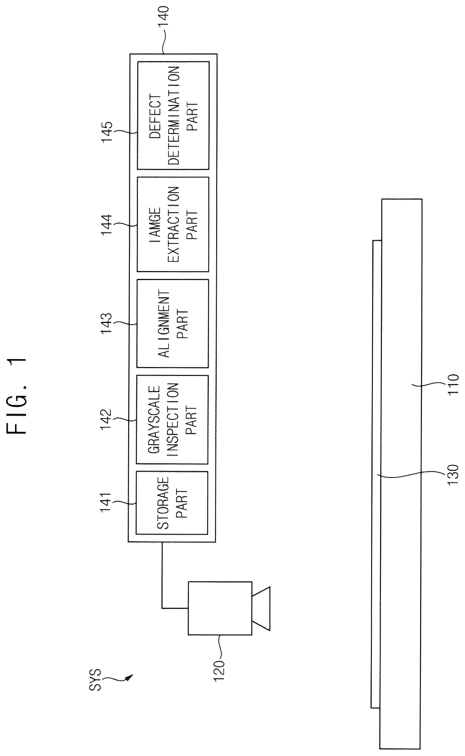
is a diagram illustrating a display device inspection system according to an embodiment.
Referring to , an embodiment of a display device inspection system SYS may include a stage 110 , on which a target substrate 130 is disposed, a camera 120 , and a processing part (or a processor) 140 . The processing part 140 may include a storage part 141 , a grayscale inspection part 142 , an alignment part 143 , an image extraction part 144 , and a defect determination part 145 .
The target substrate 130 may be disposed on the stage 110 .
The camera 120 may photograph the target substrate 130 disposed on the stage 110 . Accordingly, the camera 120 may acquire an photographed image of the target substrate 130 .
The storage part 141 may store the photographed image obtained by the camera 120 .
The grayscale inspection part 142 may obtain grayscale value of the photographed image. In an embodiment, for example, the grayscale inspection part 142 may generate grayscale value by converting the photographed image acquired by the camera 120 into grayscale values. In an embodiment, the grayscale inspection part 142 may generate the grayscale value having a value of 0 to 255 by detecting a grayscale of the photographed image.
The alignment part 143 may align the photographed image. In an embodiment, the photographed image may be acquired by photographing the target substrate 130 with the camera 120 while changing position of the camera 120 with respect to the target substrate 130 . In such an embodiment, the photographed image may have an alignment error. The alignment part 143 may correct the alignment error of the photographed image.
The image extraction part 144 may extract an inspection target image and at least one comparison image corresponding to or matching the inspection target image from the photographed image.
The defect determination part 145 may determine whether a defect occurs in the photographed image. In an embodiment, for example, the defect determination part 145 may compare the inspection target image with the comparison image to determine whether a defect occurs in an area where the inspection target image is captured.
is a plan view illustrating an embodiment of the target substrate of .
Referring to , an embodiment of the target substrate 130 may be a mother substrate including a plurality of patterns PN. In an embodiment, each of the plurality of patterns PN may be one display panel. But, the invention is not limited thereto. In an alternative embodiment, for example, the target substrate 130 may be various types of substrate on which repeating patterns (e.g., devices or wirings) are disposed or formed.
shows an embodiment in which the plurality of patterns PN includes first to ninth patterns PN 1 , PN 2 , PN 3 , PN 4 , PN 5 , PN 6 , PN 7 , PN 8 , and PN 9 for convenience of description. The first to ninth patterns PN 1 , PN 2 , PN 3 , PN 4 , PN 5 , PN 6 , PN 7 , PN 8 , and PN 9 may be arranged in a first direction D 1 and a second direction D 2 perpendicular to the first direction D 1 .
to are diagrams illustrating a method of testing a display device according to an embodiment.
is a flowchart illustrating a method of testing a display device according to an embodiment.
Referring to , an embodiment of a method S 1000 of testing a display device may include obtaining a photographed image by photographing the target substrate 130 including the plurality of patterns PN (S 100 ), obtaining grayscale values of the plurality of patterns PN by grayscaling the photographed image (S 200 ), determining an inspection target pattern from among the plurality of patterns PN (S 300 ), obtaining a first comparison value by comparing a grayscale value of the inspection target pattern with a grayscale value of a first vertically adjacent pattern (S 400 ), obtaining a second comparison value by comparing the grayscale value of the inspection target pattern with a grayscale value of a first diagonally adjacent pattern (S 500 ), obtaining a compensated comparison value by compensating the first comparison value based on the second comparison value (S 600 ), and determining a defect of the inspection target pattern based on the compensated comparison value (S 700 ).
The obtaining the photographed image (S 100 ) may include photographing the target substrate 130 with the camera 120 and storing the photographed image.
The obtaining the grayscale value (S 200 ) may include generating the grayscale value by identifying a grayscale of the photographed image. In an embodiment, the grayscale value may have a value of 0 to 255.
In determining the inspection target pattern (S 300 ), any one of the first to ninth patterns PN 1 , PN 2 , PN 3 , PN 4 , PN 5 , PN 6 , PN 7 , PN 8 , and PN 9 may be set as the inspection target pattern. Hereinafter, for convenience of description, an embodiment in which the fifth pattern PN 5 is the inspection target pattern will be described.
The eight pattern PN 8 adjacent to the inspection target pattern PN 5 in the first direction D 1 may be referred to as the first vertically adjacent pattern. The ninth pattern PN 9 adjacent to the inspection target pattern PN 5 in a third direction D 3 crossing the first direction D 1 and the second direction D 2 may be referred to as the first diagonally adjacent pattern. In such an embodiment, an angle formed by the first direction D 1 and the second direction D 3 may be greater than 0° and less than 90°. In an embodiment, for example, the angle formed by the first direction D 1 and the third direction D 3 may be greater than about 35° and smaller than about 55°.
, , , , and are diagrams illustrating the obtaining the first comparison value (S 400 ) and the obtaining the second comparison value (S 500 ) of .
Referring to , , and , the obtaining the first comparison value CV 1 (S 400 ) may include obtaining a first vertical difference value DV 1 by obtaining a difference between the grayscale value GV_PN 5 of the inspection target pattern PN 5 and a grayscale value GV_PN 8 of the first vertically adjacent pattern PN 8 (S 410 ) and determining the first vertical difference value DV 1 as the first comparison value CV 1 when the first vertical difference value DV 1 is greater than a first reference value RV 1 (S 420 ).
The first vertical difference value DV 1 may be an absolute value of a value obtained by subtracting the grayscale value GV_PN 5 of the inspection target pattern PN 5 from the grayscale value GV_PN 8 of the first vertically adjacent pattern PN 8 . In an embodiment, for example, as shown in , each of the grayscale value GV_PN 5 of the inspection target pattern PN 5 and the grayscale value GV_PN 8 of the first vertically adjacent pattern PN 8 may include grayscale values of 0 to 255. In such an embodiment, as shown in , the absolute value of the difference between the grayscale value GV_PN 5 of the inspection target pattern PN 5 and the grayscale value GV_PN 8 of the first vertically adjacent pattern PN 8 may be the first vertical difference value DV 1 including values of 0 to 255.
The first comparison value CV 1 may be a value obtained by extracting a value greater than the first reference value RV 1 from the first vertical difference value DV 1 . The first reference value RV 1 may be an arbitrarily set value. In an embodiment, for example, as shown in , the first reference value RV 1 may be set to 15. In such an embodiment, a value greater than 15 among the values included in the first vertical difference value DV 1 may be extracted and defined as the first comparison value CV 1 .
Referring to , , and , the obtaining the second comparison value CV 2 (S 500 ) may include obtaining a first diagonal difference value DV 2 by obtaining a difference between the grayscale value GV_PN 5 of the inspection target pattern PN 5 and the grayscale value GV_PN 9 of the first diagonally adjacent pattern PN 9 (S 510 ) and determining the first diagonal difference value DV 2 as the second comparison value CV 2 when the first diagonal difference value DV 2 is greater than a second reference value RV 2 (S 520 ).
The first diagonal difference value DV 2 may be an absolute value of a value obtained by subtracting the grayscale value GV_PN 5 of the inspection target pattern PN 5 from the grayscale value GV_PN 9 of the first diagonally adjacent pattern PN 9 . In an embodiment, for example, as shown in , each of the grayscale value GV_PN 5 of the inspection target pattern PN 5 and the grayscale value GV_PN 9 of the first diagonally adjacent pattern PN 9 may include grayscale values of 0 to 255. In such an embodiment, as shown in , the absolute value of the difference between the grayscale value GV_PN 5 of the inspection target pattern PN 5 and the grayscale value GV_PN 9 of the first diagonally adjacent pattern PN 9 may be the first diagonal difference value DV 2 .
The second comparison value CV 2 may be a value obtained by extracting a value greater than the second reference value RV 2 from the first diagonal difference value DV 2 . The second reference value RV 2 may be an arbitrarily set value. In an embodiment, for example, as shown in , the second reference value RV 2 may be set to 10. In such an embodiment, a value greater than 10 among the values included in the first diagonal difference value DV 2 may be extracted and defined as the second comparison value CV 2 .
In an embodiment, the first reference value RV 1 and the second reference value RV 2 may be different from each other. In an embodiment, for example, the first reference value RV 1 may be greater than the second reference value RV 2 .
, , and are diagrams illustrating the obtaining the compensated comparison value (S 600 ) of .
Referring to , , and , the obtaining the compensated comparison value CCV (S 600 ) may include obtaining a comparison difference value CDV by obtaining a difference between the first comparison value CV 1 and the second comparison value CV 2 (S 610 ) and determining the first comparison value CV 1 as the compensated comparison value CCV when the comparison difference value CDV is equal to or less than a third reference value RV 3 (S 620 ).
The comparison difference value CDV may be an absolute value of a value obtained by subtracting the first comparison value CV 1 from second comparison value CV 2 . In an embodiment where the second comparison value CV 2 corresponding to the first comparison value CV 1 is not defined, the second comparison value CV 2 corresponding to the first comparison value CV 1 may be set to zero. In an embodiment where the first comparison value CV 1 corresponding to the second comparison value CV 2 is not defined, the first comparison value CV 1 corresponding to the second comparison value CV 2 may be set to zero.
Values having a value equal to or less than the third reference value RV 3 may be extracted from the comparison difference value CDV. The first comparison value CV 1 corresponding to the values having a value equal to or less than the third reference value RV 3 in the comparison difference value CDV may be set as the compensated comparison value CCV. The third reference value RV 3 may be an arbitrarily set value. In an embodiment, for example, when the third reference value RV 3 is set to 20, after values having a value of 20 or less are extracted from the comparison difference value CDV, the first comparison value CV 1 corresponding thereto may be set as the compensated comparison value CCV.
is a diagram illustrating determining a defect of the inspection target pattern (S 700 ) of .
Referring to , the defect DF of the inspection target pattern PN 5 may be detected from the compensated comparison value CCV.
The inspection target pattern PN 5 may include the defect DF such as being pressed or dented. The defect DF may be detected by a grayscale difference between the inspection target pattern PN 5 and patterns (e.g., PN 8 or PN 9 ) adjacent to the inspection target pattern PN 5 . In an embodiment of the method of testing the display device, the compensated comparison value CCV may represent the grayscale difference. Accordingly, position and size of the defect DF in the inspection target pattern PN 5 may be detected from or based on the compensated comparison value CCV.
, , and are diagrams illustrating the obtaining the first comparison value (S 400 ′) according to an embodiment.
Referring to , , and , in an embodiment, the obtaining the first comparison value CV 1 ′ (S 400 ′) may include obtaining a first vertical difference value V_DV 1 by obtaining a difference between the grayscale value GV_PN 5 of the inspection target pattern PN 5 and a grayscale value GV_PN 8 of the first vertically adjacent pattern PN 8 (S 410 ′), obtaining a second vertical difference value V_DV 2 by obtaining a difference between the grayscale value GV_PN 5 of the inspection target pattern PN 5 and a grayscale value of a second vertically adjacent pattern adjacent to the inspection target pattern PN 5 in a direction opposite to the first direction D 1 (S 420 ′), obtaining an interpolated value ITV by interpolating the first vertical difference value V_DV 1 and the second vertical difference value V_DV 2 (S 430 ′), and determining the interpolated value ITV as the first comparison value CV 1 ′ when interpolated value ITV is greater than the first reference value RV 1 (S 440 ′).
In such an embodiment, the obtaining the first vertical difference value V_DV 1 may be substantially the same as obtaining the first vertical difference value DV 1 described with reference , , and .
In such an embodiment, the obtaining the second vertical difference value V_DV 2 may be substantially the same as the obtaining the first vertical difference value DV 1 described with reference , , and except that the inspection target pattern PN 5 and the second vertically adjacent pattern PN 2 are compared.
In the obtaining the interpolated value ITV, the interpolated value ITV may be a value between the first vertical difference value V_DV 1 and the second vertical difference value V_DV 2 . In an embodiment, as show in and , the interpolated value ITV may be an average of the first vertical difference value V_DV 1 and the second vertical difference value V_DV 2 .
The first comparison value CV 1 ′ may be a value obtained by extracting a value greater than the first reference value RV 1 from the interpolated value ITV. The first reference value RV 1 may be an arbitrary set value. In an embodiment, for example, as shown in , the first reference value RV 1 may be set to 15. In such an embodiment, values having a value greater than 15 among values included in the interpolated value ITV may be extracted and may be defined as first comparison value CV 1 ′.
is a diagram illustrating the obtaining the second comparison value (S 500 ′) according to an embodiment.
Referring to and , in an embodiment, the obtaining the second comparison value (S 500 ′) may include obtaining a first diagonal difference value by obtaining a difference between the grayscale value of the inspection target pattern PN 5 and the grayscale value of the first diagonally adjacent pattern PN 9 (S 510 ′), obtaining a second diagonal difference value by obtaining a difference between the grayscale value of the inspection target pattern PN 5 and a grayscale value of the second diagonally adjacent pattern PN 1 adjacent to the inspection target pattern PN 5 in a direction opposite to the third direction D 3 (S 520 ′), obtaining a third diagonal difference value by obtaining a difference between the grayscale value of the inspection target pattern PN 5 and a grayscale value of the third diagonally adjacent pattern PN 7 adjacent to the inspection target pattern PN 5 in a fourth direction D 4 crossing the first direction D 1 and the second direction D 2 (S 530 ′), obtaining a fourth diagonal difference value by obtaining a difference between the grayscale value of the inspection target pattern PN 5 and a grayscale value of the fourth diagonally adjacent pattern PN 3 adjacent to the inspection target pattern PN 5 in a direction opposite to the fourth direction D 4 (S 540 ′), and obtaining the second comparison value from the first diagonal difference value, the second diagonal difference value, the third diagonal difference value, and the fourth diagonal difference value.
In such an embodiment, the obtaining the first diagonal difference value (S 510 ′) may be substantially the same as the obtaining the first diagonal difference value DV 2 (S 510 ) described with reference to , , and .
In such an embodiment, the obtaining the second diagonal difference value (S 520 ′) may be substantially the same as the obtaining the first diagonal difference value DV 2 (S 510 ) described with reference to , , and except that the inspection target pattern PN 5 and the second diagonally adjacent pattern PN 1 are compared.
In such an embodiment, the obtaining the third diagonal difference value (S 530 ′) may be substantially the same as the obtaining the first diagonal difference value DV 2 (S 510 ) described with reference to , , and except that the inspection target pattern PN 5 and the third diagonally adjacent pattern PN 7 are compared.
In such an embodiment, the obtaining the fourth diagonal difference value (S 540 ′) may be substantially the same as obtaining the first diagonal difference value DV 2 (S 510 ) described with reference to , , and except that the inspection target pattern PN 5 and the fourth diagonally adjacent pattern PN 3 are compared.
In such an embodiment, the obtaining the second comparison value (S 550 ′) may include obtaining an interpolated value by interpolating the first diagonal difference value, the second diagonal difference value, the third diagonal difference value, and the fourth diagonal difference value, and determining the interpolated value as the second comparison value when the interpolated value is greater than the second reference value.
is diagram illustrating a method of testing a display device according to an alternative embodiment.
Referring to , in an alternative embodiment of a method of testing a display device A 1000 may include obtaining a photographed image by photographing a target substrate 130 including a plurality of patterns PN (A 100 ), obtaining grayscale values of the plurality of patterns PN by grayscaling the photographed image (A 200 ), determining an inspection target pattern among the plurality of patterns PN (A 300 ), obtaining a first comparison value by comparing a grayscale value of the inspection target pattern with a grayscale value of a first vertically adjacent pattern and a grayscale value of a first horizontally adjacent pattern (A 400 ), obtaining a second comparison value by comparing the grayscale value of the inspection target pattern with a grayscale value of a first diagonally adjacent pattern (A 500 ), obtaining a compensated comparison value by compensating the first comparison value based on the second comparison value (A 600 ), and determining a defect of the inspection target pattern based on the compensated comparison value (A 700 ).
In such an embodiment, the obtaining the photographed image (A 100 ) may include photographing the target substrate 130 with the camera 120 and storing the photographed image.
In such an embodiment, the obtaining the grayscale value (A 200 ) may include generating the grayscale value by identifying a grayscale of the photographed image. In an embodiment, the grayscale value may have a value of 0 to 255.
In the determining the inspection target pattern (A 300 ), any one of the first to ninth patterns PN 1 , PN 2 , PN 3 , PN 4 , PN 5 , PN 6 , PN 7 , PN 8 , and PN 9 may be set as the inspection target pattern. Hereinafter, for convenience of description, an embodiment in which the fifth pattern PN 5 is the inspection target pattern will be described.
In such an embodiment, the eight pattern PN 8 adjacent to the inspection target pattern PN 5 in the first direction D 1 may be referred to as the first vertically adjacent pattern. The sixth pattern PN 6 adjacent to the inspection target pattern PN 5 in a second direction D 2 may be referred to as the horizontally adjacent pattern. The ninth pattern PN 9 adjacent to the inspection target pattern PN 5 in a third direction D 3 crossing the first direction D 1 and the second direction D 2 may be referred to as the diagonally adjacent pattern. In such an embodiment, an angle formed by the first direction D 1 and the second direction D 3 may be greater than about 0° and less than about 90°. In an embodiment, for example, the angle formed by the first direction D 1 and the third direction D 3 may be greater than about 35° and smaller than about 55°.
In such an embodiment, the obtaining the second comparison value (A 500 ), obtaining the compensated comparison value (A 600 ), and the determining the defect of the inspection target pattern (A 700 ) may be substantially the same as the obtaining the second comparison value (S 500 ), the obtaining the compensated comparison value (S 600 ), and the determining the defect of the inspection target pattern (S 700 ) described with reference to to .
is a diagram illustrating obtaining the first comparison value (A 400 ).
Referring to , the obtaining the first comparison value (A 400 ) may include obtaining a first vertical difference value by obtaining a difference between the grayscale value of the inspection target pattern PN 5 and the grayscale value of the first vertically adjacent pattern PN 8 (A 410 ), obtaining a first horizontal difference value by obtaining a difference between the grayscale value of the inspection target pattern PN 5 and the grayscale value of the first horizontally adjacent pattern PN 6 (A 420 ), obtaining an interpolated value by interpolating the first vertical difference value and the first horizontal difference value (A 430 ), and determining the interpolation value as the first comparison value when interpolated value is greater than a second reference value (A 440 ).
In an embodiment, the interpolated value may be a value between the first vertical difference value and the first horizontal difference value. In an embodiment, for example, the interpolated value may be an average of the first vertical difference value and the first horizontal difference value.
In an embodiment, the obtaining the first comparison value (A 400 ) may further include obtaining a second vertical difference value by obtaining a difference between the grayscale value of the inspection target pattern PN 5 and a grayscale value of a second vertically adjacent pattern PN 2 adjacent to the inspection target pattern PN 5 in a direction opposite to the first direction D 1 . In such an embodiment, the obtaining the interpolated value (A 430 ) may include obtaining the interpolated value by interpolating the first vertical difference value, the second vertical difference value, and the first horizontal difference value.
In an embodiment, the obtaining the first comparison value (A 400 ) may further include obtaining a second horizontal difference value by obtaining a difference between the grayscale value of the inspection target pattern PN 5 and a grayscale value of a second horizontally adjacent pattern PN 4 adjacent to the inspection target pattern PN 5 in a direction opposite to the second direction D 2 . In such an embodiment, obtaining the interpolated value (A 430 ) may include obtaining the interpolated value by interpolating the first vertical difference value, the first horizontal difference value, and the second horizontal difference value.
According to embodiments of the invention, a method of testing a display device may include obtaining a first comparison value by comparing a gradation value of an inspection target pattern and a gradation value of a first vertically adjacent pattern, obtaining a second comparison value by comparing the gradation value of an inspection target pattern and a gradation value of a first diagonally adjacent pattern, and obtaining a compensated comparison value by compensating the first comparison value based on the second comparison value. Accordingly, defect detection accuracy may be improved.
The invention should not be construed as being limited to the embodiments set forth herein. Rather, these embodiments are provided so that this disclosure will be thorough and complete and will fully convey the concept of the invention to those skilled in the art.
While the invention has been particularly shown and described with reference to embodiments thereof, it will be understood by those of ordinary skill in the art that various changes in form and details may be made therein without departing from the spirit or scope of the invention as defined by the following claims.
Figures (14)
Citations
This patent cites (6)
- US2006/0067571
- US105205803
- US2004219291
- US2009122046
- US102172246
- USI693629