Cooling System and Control Method of Cooling System
Abstract
A cooling system and a control method of the cooling system are provided. The cooling system includes a display device, a temperature sensor, a cooling fan and a temperature controller. The display device includes a backlight module. The temperature sensor is configured in the backlight module. The temperature sensor senses a first temperature of the backlight module and a second temperature of the backlight module. The first temperature is higher than the second temperature. The cooling fan is configured in the backlight module. The cooling fan provides a cooling path. The temperature controller receives the first temperature and the second temperature from the temperature sensor, and controls the cooling fan to enable or disable.
Claims (17)
1. A cooling system, comprising: a display device, configured to display an image, wherein the display device comprises a backlight module; a temperature sensor, configured in the backlight module, and configured to sense a first temperature of the backlight module and a second temperature of the backlight module, wherein the first temperature is higher than the second temperature; a cooling fan, configured in the backlight module, and configured to provide a cooling path; and a temperature controller, configured to receive the first temperature and the second temperature from the temperature sensor, and control the cooling fan to enable or disable; wherein the backlight module is disabled after disabling the cooling fan.
10. A control method of a cooling system, wherein the cooling system comprises a display device, a temperature sensor and a cooling fan, wherein the control method comprises: detecting a status of a backlight module of the display device; controlling the temperature sensor to sense a temperature of the backlight module after the backlight module is started up; enabling the cooling fan when the temperature of the backlight module sensed by the temperature sensor is higher than a first temperature; disabling the cooling fan when the temperature is lower than a second temperature, wherein the first temperature is higher than the second temperature; and disabling the backlight module after disabling the cooling fan.
12. A cooling system, comprising: a power circuit, configured to provide a driving power; a temperature sensor, configured in a cockpit, and configured to sense a first temperature of the cockpit and a second temperature of the cockpit, wherein the first temperature is higher than the second temperature; a cooling fan, configured in the cockpit, and configured to provide a cooling path; a temperature controller, configured to receive the first temperature and the second temperature from the temperature sensor, and control the cooling fan to enable or disable; and a display device, configured to display an image, wherein the display device comprises a backlight module, and wherein the backlight module is started up when the cooling fan is disabled.
Show 14 dependent claims
2. The cooling system of claim 1 , further comprising: an air-conditioning system, electrically connected to the temperature controller, and configured to be turned on when the cooling fan is enabled.
3. The cooling system of claim 1 , further comprising: an air-conditioning system, electrically connected to the temperature controller, wherein the backlight module is enabled after the air-conditioning system is enabled.
4. The cooling system of claim 1 , wherein a driving power of the cooling fan is provided by a driving power of the backlight module.
5. The cooling system of claim 1 , wherein a driving power of the cooling fan is different from a driving power of the backlight module.
6. The cooling system of claim 1 , wherein when a temperature of the backlight module sensed by the temperature sensor is higher than the first temperature, the temperature controller enables the cooling fan.
7. The cooling system of claim 1 , wherein when a temperature of the backlight module sensed by the temperature sensor is lower than the second temperature, the temperature controller disables the cooling fan.
8. The cooling system of claim 1 , wherein the temperature sensor starts to sense a temperature of the backlight module after the backlight module is started up.
9. The cooling system of claim 8 , wherein the display device displays the temperature of the backlight module.
11. The cooling system of claim 10 , further comprising: disabling the backlight module before disabling the cooling fan.
13. The cooling system of claim 12 , further comprising: an air-conditioning system, electrically connected to the temperature controller, and configured to enable the cooling fan according to the first temperature.
14. The cooling system of claim 12 , further comprising: a car-machine system, electrically connected to the temperature controller, wherein the temperature controller is started up when the car-machine system is started up.
15. The cooling system of claim 14 , wherein the driving power of the cooling system is provided by the car-machine system.
16. The cooling system of claim 12 , wherein when a temperature sensed by the temperature sensor is higher than the first temperature, the temperature controller enables the cooling fan.
17. The cooling system of claim 12 , wherein when a temperature sensed by the temperature sensor is lower than the second temperature, the temperature controller disables the cooling fan.
Full Description
Show full text →
CROSS-REFERENCE TO RELATED APPLICATION
This application claims the priority benefit of U.S. Provisional application Ser. No. 63/433,760, filed on Dec. 20, 2022. The entirety of the above-mentioned patent application is hereby incorporated by reference herein and made a part of this specification.
BACKGROUND
Technical Field
The disclosure generally relates to a cooling system and a control method of the cooling system, and more particularly to a cooling system of a vehicle and a control method of the cooling system.
Description of Related Art
Generally, vehicles are used extensively as means of movement. In order to improve a riding comfort of the user, an air conditioning system may be provided within the vehicles. However, recent vehicles include electronic devices (for example, a display and/or an electronic dashboard). How to take into account the ride comfort in the vehicles and a cooling mechanism of the electronic devices are one of the research and development focuses of those skilled in the art.
SUMMARY
The disclosure is related to a cooling system and a control method of the cooling system.
The disclosure provides a cooling system. The cooling system includes a display device, a temperature sensor, a cooling fan and a temperature controller. The display device displays an image. The display device includes a backlight module. The temperature sensor is configured in the backlight module. The temperature sensor senses a first temperature of the backlight module and a second temperature of the backlight module. The first temperature is higher than the second temperature. The cooling fan is configured in the backlight module. The cooling fan provides a cooling path. The temperature controller receives the first temperature and the second temperature from the temperature sensor, and controls the cooling fan to enable or disable.
The disclosure provides a control method of a cooling system. The cooling system includes a display device, a temperature sensor and a cooling fan. The control method includes: detecting a status of a backlight module of the display device; controlling the temperature sensor to sense a temperature of the backlight module after the backlight module is started up; enabling the cooling fan when the temperature of the backlight module sensed by the temperature sensor is higher than a first temperature; and disabling the cooling fan when the temperature is lower than a second temperature. The wherein the first temperature is higher than the second temperature.
The disclosure provides another cooling system. The cooling system includes a driving power, a temperature sensor, a cooling fan and a temperature controller. The temperature sensor is configured in a cockpit. The temperature sensor senses a first temperature of the cockpit and a second temperature of the cockpit. The first temperature is higher than the second temperature. The cooling fan is configured in the cockpit. The cooling fan provides a cooling path. The temperature controller receives the first temperature and the second temperature from the temperature sensor, and controls the cooling fan to enable or disable.
To make the aforementioned more comprehensible, several embodiments accompanied with drawings are described in detail as follows.
BRIEF DESCRIPTION OF THE DRAWINGS
The accompanying drawings are included to provide a further understanding of the disclosure, and are incorporated in and constitute a part of this specification. The drawings illustrate exemplary embodiments of the disclosure and, together with the description, serve to explain the principles of the disclosure.
illustrates a schematic diagram of a cooling system according to an embodiment of the disclosure.
illustrates cooling modes of a cooling system according to an embodiment of the disclosure.
A illustrates a flow chart of a control method according to an embodiment of the disclosure.
B illustrates a flow chart of a control method according to an embodiment of the disclosure.
C illustrates a flow chart of a control method according to an embodiment of the disclosure.
A illustrates a flow chart of a control method according to an embodiment of the disclosure.
B illustrates a flow chart of a control method according to an embodiment of the disclosure.
A illustrates a flow chart of a control method according to an embodiment of the disclosure.
B illustrates a flow chart of a control method according to an embodiment of the disclosure.
illustrates a flow chart of a control method according to an embodiment of the disclosure.
A and B illustrate a flow chart of a control method according to an embodiment of the disclosure.
illustrates a flow chart of a control method according to an embodiment of the disclosure.
illustrates a flow chart of a control method according to an embodiment of the disclosure.
A and B illustrates a flow chart of a control method according to an embodiment of the disclosure.
illustrates a schematic diagram of a backlight module and a cooling fan according to an embodiment of the disclosure.
DESCRIPTION OF THE EMBODIMENTS
A disclosure may be understood by reference to the following detailed description, taken in conjunction with the drawings as described below. It is noted that, for purposes of illustrative clarity and being easily understood by the readers, various drawings of this disclosure show a portion of an electronic device, and certain elements in various drawings may not be drawn to scale. In addition, the number and dimension of each device shown in drawings are only illustrative and are not intended to limit the scope of a disclosure.
Certain terms are used throughout the description and following claims to refer to particular components. As one skilled in the art will understand, electronic equipment manufacturers may refer to a component by different names. This document does not intend to distinguish between components that differ in name but not function. In the following description and in the claims, the terms “include”, “comprise” and “have” are used in an open-ended fashion, and thus should be interpreted to mean “include, but not limited to . . . ”. Thus, when the terms “include”, “comprise” and/or “have” are used in the description of a disclosure, the corresponding features, areas, steps, operations and/or components would be pointed to existence, but not limited to the existence of one or a plurality of the corresponding features, areas, steps, operations and/or components.
It will be understood that when an element is referred to as being “coupled to”, “connected to”, or “conducted to” another element, it may be directly connected to the other element and established directly electrical connection, or intervening elements may be presented therebetween for relaying electrical connection (indirectly electrical connection). In contrast, when an element is referred to as being “directly coupled to”, “directly conducted to”, or “directly connected to” another element, there are no intervening elements presented.
Although terms such as first, second, third, etc., may be used to describe diverse constituent elements, such constituent elements are not limited by the terms. The terms are used only to discriminate a constituent element from other constituent elements in the specification. The claims may not use the same terms, but instead may use the terms first, second, third, etc. with respect to the order in which an element is claimed. Accordingly, in the following description, a first constituent element may be a second constituent element in a claim.
In a disclosure, the embodiments use “pixel” or “pixel unit” as a unit for describing a specific region including at least one functional circuit for at least one specific function. Describing “pixel with circuit” as “circuit” is available for a disclosure. For example, a “pixel with current source” may be described as a “current source”, or a “pixel with current sink” may be described as a “current sink”. The region of a “pixel” is depended on a unit for providing a specific function, adjacent pixels may share the same parts or wires, but may also include its own specific parts therein. For example, adjacent pixels may share a same scan line or a same data line, but the pixels may also have their own transistors or capacitance.
In a disclosure, a current source circuit is a circuit unit for outputting current, and a current sink is a circuit unit for draining current. The adjacent circuit units may share the same parts or wires and may also include its specific parts therein.
It should be noted that the technical features in different embodiments described in the following can be replaced, recombined, or mixed with one another to constitute another embodiment without departing from the spirit of a disclosure.
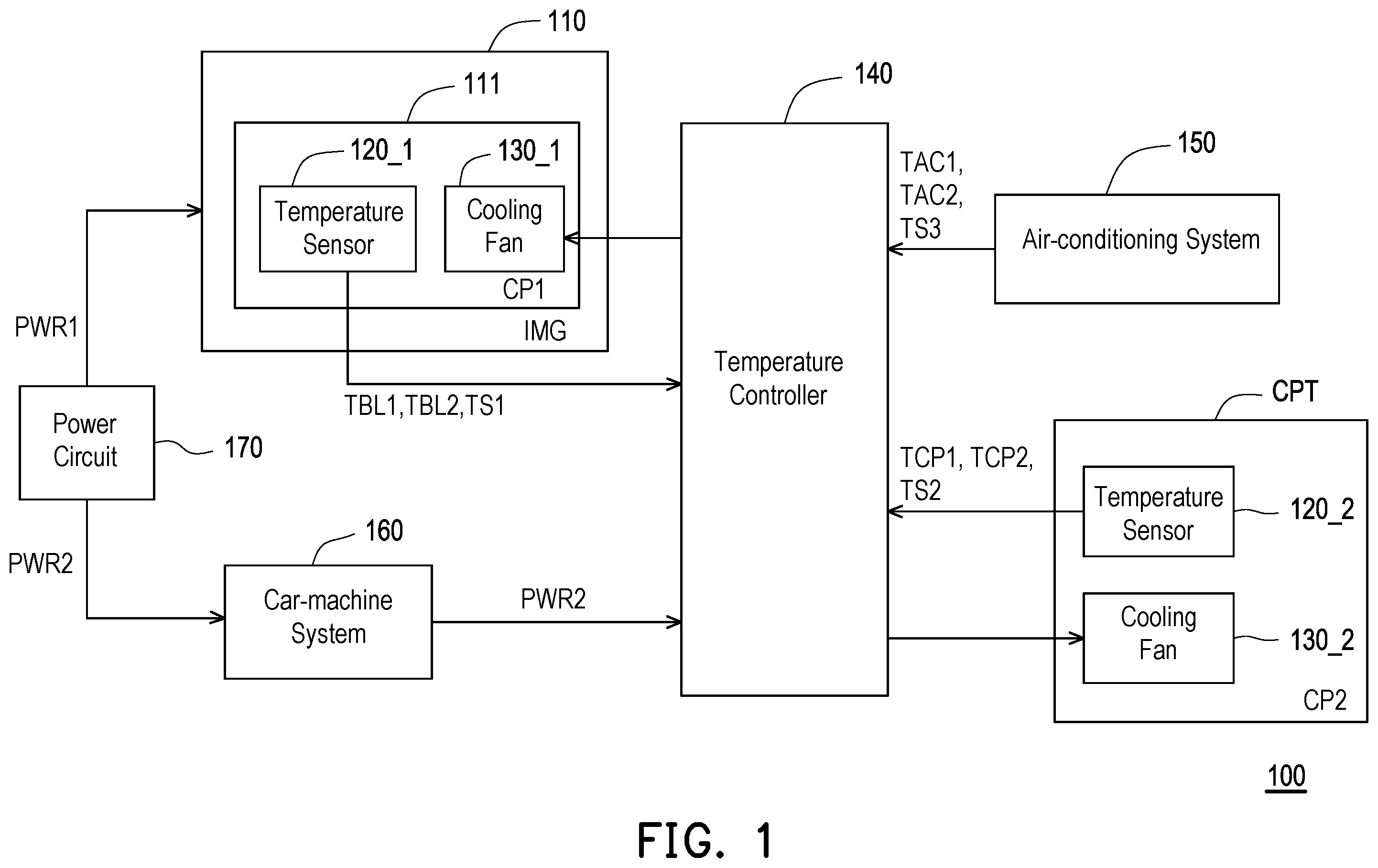
illustrates a schematic diagram of a cooling system according to an embodiment of the disclosure. Referring to , in the embodiment, a cooling system 100 is used for a vehicle. The cooling system 100 includes a display device 110 , temperature sensors 120 _ 1 , 120 _ 2 , a cooling fans 130 _ 1 , 130 _ 2 , a temperature controller 140 , an air-conditioning system 150 , a car-machine system 160 and a power circuit 170 . The display device 110 displays an image IMG.
The display device 110 includes a backlight module 111 . For example, the display device 110 may be an electronic dashboard, a navigation display device, an alarm display device and/or a status display device of the vehicle, but not be limited thereto.
In the embodiment, the temperature sensor 120 _ 1 is configured in the backlight module 111 . The temperature sensor 120 _ 1 senses a first temperature TBL 1 of the backlight module 111 and a second temperature TBL 2 of the backlight module 111 . The first temperature TBL 1 is higher than the second temperature TBL 2 . Both the first temperature TBL 1 and the second temperature TBL 2 are default temperatures for the backlight module 111 .
The cooling fan 130 _ 1 is configured in the backlight module 111 . The cooling fan 130 _ 1 provides a cooling path CP 1 in the backlight module 111 . The temperature controller 140 is electrically connected to the display device 110 , the temperature sensor 120 _ 1 , the cooling fans 130 _ 1 and the air-conditioning system 150 . In the embodiment, the temperature controller 140 receives the first temperature TBL 1 and the second temperature TBL 2 from the temperature sensor 120 _ 1 , and controls the cooling fan 130 _ 1 to enable or disable.
In the embodiment, the temperature sensor 120 _ 2 is configured in a cockpit CPT of the vehicle. The temperature sensor 120 _ 2 senses a first temperature TCP 1 of the cockpit CPT and a second temperature TCP 2 of the cockpit CPT. The first temperature TCP 1 is higher than the second temperature TCP 2 . Both the first temperature TCP 1 and the second temperature TCP 2 are default temperatures for the cockpit CPT. For example, the temperature sensor 120 _ 2 may be configured on a vehicle seat in the cockpit CPT or configured near the vehicle seat in the cockpit CPT, but not be limited thereto.
The cooling fan 130 _ 2 is configured in the cockpit CPT. The cooling fan 130 _ 2 provides a cooling path CP 2 . The temperature controller 140 is further electrically connected to the temperature sensor 120 _ 2 , the cooling fans 130 _ 2 . The temperature controller 140 receives the first temperature TCP 1 and the second temperature TCP 2 from the temperature sensor 120 _ 2 , and controls the cooling fan 130 _ 2 to enable or disable.
In the embodiment, the air-conditioning system 150 is electrically connected to the temperature controller. The air-conditioning system 150 is used to control the temperature inside the vehicle. In the embodiment, the car-machine system 160 is electrically connected to the temperature controller 140 . The car-machine system 160 is used to integrate and process an information of the vehicle, such as audio-visual entertainment, communication related to Internet of Vehicles technology and/or navigation, but not be limited thereto. In some embodiments, the car-machine system 160 is electrically connected to the display device 110 .
In the embodiment, the power circuit 170 provides driving powers PWR 1 , PWR 2 . The power circuit 170 provides the driving power PWR 1 to drive the display device 110 . The power circuit 170 provides the driving power PWR 2 to drive the car-machine system 160 . In an embodiment, the driving power PWR 1 may be equal to the driving power PWR 2 . In another embodiment, the driving power PWR 1 may be different from the driving power PWR 2 .
In the embodiment, a driving power of the cooling system 100 is provided by the car-machine system 160 . In the embodiment, at least the temperature controller 140 is driven by a driving power PWR 2 provided by the car-machine system 160 .
illustrates cooling modes of a cooling system according to an embodiment of the disclosure. Referring to and , in the embodiment, the cooling system 100 can operate in at least one of a first cooling mode CM 1 , a second cooling mode CM 2 and a third cooling mode CM 3 . In the first cooling mode CM 1 , the temperature controller 140 controls the cooling fan 130 _ 2 according to a temperature TS 2 in the cockpit CPT. In the second cooling mode CM 2 , the temperature controller 140 controls the air-conditioning system 150 according to a temperature TS 3 in the vehicle. In the third cooling mode CM 3 , the temperature controller 140 controls the cooling fan 130 _ 1 according to a temperature TS 1 in the backlight module 111 .
A illustrates a flow chart of a control method according to an embodiment of the disclosure Referring to and A , in the embodiment, a control method S 100 is used for the cooling system 100 . The control method S 100 includes steps S 101 to S 106 . After the car-machine system 160 is driven by the power circuit 170 , a cooling mode is started up. The temperature controller 140 is started up when the car-machine system 160 is started up. The temperature controller 140 receives the temperature TS 2 in the cockpit CPT from the temperature sensor 120 _ 2 in the step S 101 . The temperature controller 140 determines the temperature TS 2 in the step S 102 . When the temperature TS 2 is higher than the first temperature TCP 1 (for example, 28±3° C., but not be limited thereto), the temperature controller 140 judges that the temperature TS 2 exceeds a sensitive temperature range of a user in the cockpit CPT. Therefore, the temperature controller 140 enables the cooling fan 130 _ 2 in the step S 103 . In the step S 103 , the cooling fan 130 _ 2 operates to decrease the temperature TS 2 in the cockpit CPT. In the step S 104 , the temperature controller 140 determines the temperature TS 2 . When the temperature TS 2 is higher than or equal to the second temperature TCP 2 (for example, 22±3° C., but not be limited thereto), the temperature controller 140 operates in the step S 103 . On the other hand, when the temperature TS 2 is lower than the second temperature TCP 2 , the temperature controller 140 judges that the temperature TS 2 is in the sensitive temperature range of the user in the cockpit CPT. Therefore, the temperature controller 140 disables the cooling fan 130 _ 2 in the step S 105 .
In the step S 102 , when the temperature TS 2 is lower than or equal to the first temperature TCP 1 , the temperature controller 140 disables the cooling fan 130 _ 2 in the step S 105 .
In the step S 106 , the temperature controller 140 determines whether to continue the cooling mode. When the cooling mode continues to operate, the temperature controller 140 operates in the step S 102 . When the cooling mode is finished, the cooling system 100 finishes the control method S 100 .
The cooling mode of the control method S 100 is the first cooling mode CM 1 as shown in the . In some embodiment, based on the cooling mode of the control method S 100 , the cooling system 100 may be simplified. For example, the temperature sensor 120 _ 1 and the cooling fan 130 _ 1 can be omitted.
B illustrates a flow chart of a control method according to an embodiment of the disclosure. Referring to and B , in the embodiment, a control method S 200 is used for the cooling system 100 . The control method S 200 includes steps S 201 to S 209 . After the car-machine system 160 is driven by the power circuit 170 , a cooling mode is started up. The temperature controller 140 receives the temperature TS 2 in the cockpit CPT from the temperature sensor 120 _ 2 in the step S 201 . The temperature controller 140 determines the temperature TS 2 in the step S 202 . When the temperature TS 2 is higher than the first temperature TCP 1 , the temperature controller 140 enables the cooling fan 130 _ 2 in the step S 203 . In the step S 204 , the temperature controller 140 determines the temperature TS 2 . When the temperature TS 2 is higher than or equal to the second temperature TCP 2 , the temperature controller 140 operates in the step S 203 . On the other hand, when the temperature TS 2 is lower than the second temperature TCP 2 , the temperature controller 140 disables the cooling fan 130 _ 2 in the step S 205 .
After the cockpit CPT is cooled down in the step S 205 , the backlight module 111 is enabled in the step S 206 . In the embodiment, the display device 110 enables the backlight module 111 in the step S 206 and monitors a status of the backlight module 111 in the step S 207 . When the backlight module 111 does not start up, the display device 110 enables the backlight module 111 again in the step S 206 . When the backlight module 111 starts up, the temperature controller 140 determines whether to continue the cooling mode in the step S 208 . When the cooling mode continues to operate, the temperature controller 140 operates in the step S 202 . When the cooling mode is finished, the display device 110 disables the backlight module 111 in the step S 209 . After the step S 209 , the cooling system 100 finishes the control method S 200 .
The cooling mode of the control method S 200 is the first cooling mode CM 1 as shown in the . In some embodiment, based on the cooling mode of the control method S 200 , the cooling system 100 may be simplified. For example, the temperature sensor 120 _ 1 and the cooling fan 130 _ 1 can be omitted.
C illustrates a flow chart of a control method according to an embodiment of the disclosure. Referring to and C , in the embodiment, a control method S 300 is used for the cooling system 100 . The control method S 300 includes steps S 301 to S 310 . After the car-machine system 160 is driven by the power circuit 170 , a cooling mode is started up. The temperature controller 140 receives the temperature TS 2 in the cockpit CPT from the temperature sensor 120 _ 2 in the step S 301 . The cooling system 100 enables the air-conditioning system 150 in the step S 302 . For example, the air-conditioning system 150 may be enabled by the temperature controller 140 or the car-machine system 160 . The steps S 303 to S 310 is performed after the step S 302 . The steps S 303 to S 310 are similar to the steps S 202 to S 209 , so it will not be repeated here. In other words, the backlight module 111 is enabled after the air-conditioning system 150 is enabled.
Besides, in some embodiments, the air-conditioning system 150 may enable the cooling fan 130 _ 2 according to the first temperature TCP 1 . In the step S 303 , when the temperature TS 2 is higher than a first temperature TCP 1 , the air-conditioning system 150 enables the cooling fan 130 _ 2 according to the first temperature TCP 1 in the step S 304 .
A illustrates a flow chart of a control method according to an embodiment of the disclosure. Referring to and A , in the embodiment, a control method S 400 is used for the cooling system 100 . The control method S 400 includes steps S 401 to S 406 . After the air-conditioning system 150 and the car-machine system 160 is driven by the power circuit 170 , a cooling mode is started up. The temperature controller 140 receives the temperature TS 3 in the vehicle in the step S 401 . The temperature controller 140 determines the temperature TS 3 in the step S 402 . When the temperature TS 3 is higher than a first setting temperature TAC 1 (for example, 35±3° C., but not be limited thereto), the temperature controller 140 controls the air-conditioning system to decrease the temperature TS 3 in the step S 403 . In the step S 403 , the air-conditioning system 150 operates to decrease the temperature TS 3 in the vehicle. In the step S 404 , the temperature controller 140 determines the temperature TS 3 . When the temperature TS 3 is higher than or equal to a second setting temperature TAC 2 (for example, 25±3° C., but not be limited thereto), the temperature controller 140 operates in the step S 403 . On the other hand, when the temperature TS 3 is lower than the second setting temperature TAC 2 , the temperature controller 140 controls the air-conditioning system 150 to stop decreasing the temperature TS 3 in the step S 405 .
In the step S 402 , when the temperature TS 3 is lower than or equal to the first setting temperature TAC 1 , the temperature controller 140 controls the air-conditioning system 150 to stop decreasing the temperature TS 3 in the step S 405 .
In the step S 406 , the temperature controller 140 determines whether to continue the cooling mode. When the cooling mode continues to operate, the temperature controller 140 operates in the step S 402 . When the cooling mode is finished, the cooling system 100 finishes the control method S 400 .
The cooling mode of the control method S 400 is the second cooling mode CM 2 as shown in the . In some embodiment, based on the cooling mode of the control method S 400 , the cooling system 100 may be simplified. For example, the temperature sensors 120 _ 1 , 120 _ 2 and the cooling fan 130 _ 1 , 130 _ 3 can be omitted.
B illustrates a flow chart of a control method according to an embodiment of the disclosure Referring to and B , in the embodiment, a control method S 500 is used for the cooling system 100 . The control method S 500 includes steps S 501 to S 509 . After the air-conditioning system 150 and the car-machine system 160 is driven by the power circuit 170 , a cooling mode is started up. The temperature controller 140 receives the temperature TS 3 in the vehicle in the step S 501 . The temperature controller 140 determines the temperature TS 3 in the step S 502 . When the temperature TS 3 is higher than a first setting temperature TAC 1 , the temperature controller 140 controls the air-conditioning system 150 to decrease the temperature TS 3 in the step S 503 . In the step S 504 , the temperature controller 140 determines the temperature TS 3 . When the temperature TS 3 is higher than or equal to a second setting temperature TAC 2 , the temperature controller 140 operates in the step S 503 . On the other hand, when the temperature TS 3 is lower than the second setting temperature TAC 2 , the temperature controller 140 controls the air-conditioning system 150 to stop decreasing the temperature TS 3 in the step S 505 .
In the step S 502 , when the temperature TS 3 is lower than or equal to the first setting temperature TAC 1 , the temperature controller 140 controls the air-conditioning system 150 to stop decreasing the temperature TS 3 in the step S 505 .
After a compartment in the vehicle is cooled down in the step S 505 , the backlight module 111 is enabled in the step S 506 . The display device 110 enables the backlight module 111 in the step S 506 and monitors a status of the backlight module 111 in the step S 507 . When the backlight module 111 does not start up, the display device 110 enables the backlight module 111 again in the step S 506 . When the backlight module 111 starts up, the temperature controller 140 determines whether to continue the cooling mode in the step S 508 . When the cooling mode continues to operate, the temperature controller 140 operates in the step S 507 . When the cooling mode is finished, the display device 110 disables the backlight module 111 in the step S 509 . After the step S 509 , the cooling system 100 finishes the control method S 500 .
In some embodiment, when the cooling mode continues to operate, the temperature controller 140 operates in the step S 502 .
A illustrates a flow chart of a control method according to an embodiment of the disclosure. Referring to and A , in the embodiment, a control method S 600 is used for the cooling system 100 . The control method S 600 includes steps S 601 to S 609 . After the air-conditioning system 150 and the car-machine system 160 is driven by the power circuit 170 , a cooling mode is started up. The backlight module 111 is enabled in the step S 601 . The display device 110 enables the backlight module 111 in the step S 601 and monitors a status of the backlight module 111 in the step S 602 . When the backlight module 111 does not start up, the display device 110 enables the backlight module 111 again in the step S 601 .
When the backlight module 111 starts up, the temperature controller 140 starts receiving the temperature TS 3 in the vehicle in the step S 603 and determines the temperature TS 3 in the step S 604 . When the temperature TS 3 is higher than a first setting temperature TAC 1 , the temperature controller 140 controls the air-conditioning system to decrease the temperature TS 3 in the step S 605 . In the step S 606 , the temperature controller 140 determines the temperature TS 3 . When the temperature TS 3 is higher than or equal to a second setting temperature TAC 2 , the temperature controller 140 operates in the step S 605 . On the other hand, when the temperature TS 3 is lower than the second setting temperature TAC 2 , the temperature controller 140 controls the air-conditioning system 150 to stop decreasing the temperature TS 3 in the step S 607 .
In the step S 604 , when the temperature TS 3 is lower than or equal to the first setting temperature TAC 1 , the temperature controller 140 controls the air-conditioning system 150 to stop decreasing the temperature TS 3 in the step S 607 .
In the step S 608 , the temperature controller 140 determines whether to continue the cooling mode. When the cooling mode continues to operate, the temperature controller 140 operates in the step S 604 . When the cooling mode is finished, the display device 110 disables the backlight module 111 in the step S 609 and finishes the control method S 600 .
The cooling mode of the control method S 600 is the second cooling mode CM 2 as shown in the . In some embodiment, based on the cooling mode of the control method S 600 , the cooling system 100 may be simplified. For example, the temperature sensors 120 _ 1 , 120 _ 2 and the cooling fan 130 _ 1 , 130 _ 3 can be omitted.
B illustrates a flow chart of a control method according to an embodiment of the disclosure Referring to and B , in the embodiment, a control method S 700 is used for the cooling system 100 . The control method S 700 includes steps S 701 to S 709 . After the air-conditioning system 150 and the car-machine system 160 is driven by the power circuit 170 , a cooling mode is started up. The backlight module 111 is enabled in the step S 701 . The display device 110 enables the backlight module 111 in the step S 701 and monitors a status of the backlight module 111 in the step S 702 . When the backlight module 111 does not start up, the display device 110 enables the backlight module 111 again in the step S 701 .
When the backlight module 111 starts up, the temperature controller 140 receives the temperature TS 2 in the cockpit CPT from the temperature sensor 120 _ 2 in the step S 703 . The temperature controller 140 determines the temperature TS 2 in the step S 704 . When the temperature TS 2 is higher than the first temperature TCP 1 , the temperature controller 140 enables the cooling fan 130 _ 2 in the step S 705 . In the step S 706 , the temperature controller 140 determines the temperature TS 2 . When the temperature TS 2 is higher than or equal to the second temperature TCP 2 , the temperature controller 140 operates in the step S 705 . On the other hand, when the temperature TS 2 is lower than the second temperature TCP 2 , the temperature controller 140 disables the cooling fan 130 _ 2 in the step S 707 .
In the step S 704 , when the temperature TS 2 is lower than or equal to the first temperature TCP 1 , the temperature controller 140 disables the cooling fan 130 _ 2 in the step S 707 .
In the step S 708 , the temperature controller 140 determines whether to continue the cooling mode. When the cooling mode continues to operate, the temperature controller 140 operates in the step S 704 . When the cooling mode is finished, the display device 110 disables the backlight module 111 in the step S 709 and finishes the control method S 700 .
The cooling mode of the control method S 700 is the first cooling mode CM 1 as shown in the . In some embodiment, based on the cooling mode of the control method S 700 , the cooling system 100 may be simplified. For example, the temperature sensor 120 _ 1 and the cooling fan 130 _ 1 can be omitted.
illustrates a flow chart of a control method according to an embodiment of the disclosure. Referring to and , in the embodiment, a control method S 800 is used for the cooling system 100 . The control method S 800 includes steps S 801 to S 809 . The steps S 801 to S 807 are similar to the steps S 501 to S 507 , so it will not be repeated here. In the step S 808 , the temperature controller 140 determines whether to continue the cooling mode. when the cooling mode continues to operate, the temperature controller 140 operates in the step S 704 . When the cooling mode is finished, the display device 110 disables the backlight module 111 in the step S 809 and finishes the control method S 800 .
A and B illustrate a flow chart of a control method according to an embodiment of the disclosure. Referring to , A and B , in the embodiment, a control method S 900 is used for the cooling system 100 . The control method S 900 includes steps S 901 to S 913 . After the air-conditioning system 150 and the car-machine system 160 is driven by the power circuit 170 , a cooling mode is started up. The temperature controller 140 receives the temperature TS 1 in the backlight module 111 from the temperature sensor 120 _ 1 in the step S 901 . The temperature controller 140 determines the temperature TS 1 in the step S 902 . When the temperature TS 1 is higher than the first temperature TBL 1 (for example, 50±3° C., but not be limited thereto), the temperature controller 140 enables the cooling fan 130 _ 1 in the step S 903 .
In the step S 904 , the temperature controller 140 determines the temperature TS 1 . When the temperature TS 1 is higher than or equal to the second temperature TBL 2 (for example, 40±3° C., but not be limited thereto), the temperature controller 140 operates in the step S 903 . On the other hand, when the temperature TS 1 is lower than the second temperature TBL 2 , the temperature controller 140 disables the cooling fan 130 _ 1 in the step S 905 .
In the step S 902 , when the temperature TS 1 is lower than or equal to the first temperature TBL 1 , the temperature controller 140 disables the cooling fan 130 _ 1 in the step S 905 .
After the backlight module 111 is cooled down in the step S 905 , the backlight module 111 is enabled in the step S 906 . The display device 110 enables the backlight module 111 in the step S 906 and monitors a status of the backlight module 111 in the step S 907 . When the backlight module 111 does not start up, the display device 110 enables the backlight module 111 again in the step S 906 . When the backlight module 111 starts up, the temperature controller 140 determines whether to continue the cooling mode in the step S 908 . When the cooling mode continues to operate, the temperature controller 140 operates in the step S 910 . When the cooling mode is finished, the display device 110 disables the backlight module 111 in the step S 909 . After the step S 909 , the cooling system 100 finishes the control method S 900 .
In the step S 910 , the temperature controller 140 determines the temperature TS 3 . When the temperature TS 3 is higher than a first setting temperature TAC 1 , the temperature controller 140 controls the air-conditioning system to decrease the temperature TS 3 in the step S 911 . In the step S 912 , the temperature controller 140 determines the temperature TS 3 . When the temperature TS 3 is higher than or equal to a second setting temperature TAC 2 , the temperature controller 140 operates in the step S 911 . On the other hand, when the temperature TS 3 is lower than the second setting temperature TAC 2 , the temperature controller 140 controls the air-conditioning system 150 to stop decreasing the temperature TS 3 in the step S 913 . After the step S 913 , the backlight module 111 is enabled.
In the step S 910 , when the temperature TS 3 is lower than or equal to the first setting temperature TAC 1 , the temperature controller 140 controls the air-conditioning system 150 to stop decreasing the temperature TS 3 in the step S 913 .
The cooling mode of the control method S 900 includes the second cooling mode CM 2 and the third cooling mode CM 3 as shown in the . In some embodiment, based on the cooling mode of the control method S 900 , the cooling system 100 may be simplified. For example, the temperature sensor 120 _ 2 and the cooling fan 130 _ 2 can be omitted.
In the embodiment, the step S 910 is after the step S 908 . In some embodiments, the step S 910 is after one of the steps S 901 , S 902 and S 905 . Therefore, the air-conditioning system 150 is turned on when the cooling fan 130 _ 1 is enabled.
illustrates a flow chart of a control method according to an embodiment of the disclosure. Referring to and , in the embodiment, a control method S 1000 is used for the cooling system 100 . The control method S 1000 includes steps S 1001 to S 1009 . After the air-conditioning system 150 and the car-machine system 160 is driven by the power circuit 170 , a cooling mode is started up. The backlight module 111 is enabled in the step S 1001 . The display device 110 enables the backlight module 111 in the step S 1001 and monitors a status of the backlight module 111 in the step S 1002 . When the backlight module 111 does not start up, the display device 110 enables the backlight module 111 again in the step S 1001 .
When the backlight module 111 starts up, the temperature controller 140 controls the temperature sensor 120 _ 1 to sense the temperature TS 1 of the backlight module 111 in the step S 1003 . In other words, the temperature sensor 120 _ 1 starts to sense the temperature TS 1 of the backlight module 111 after the backlight module 11 is started up. Thus, the display device 110 displays the temperature TS 1 of the backlight module 111 . The user can obtain the temperature TS 1 displayed by the display device 110 . The temperature controller 140 determines the temperature TS 1 in the step S 1004 . When the temperature TS 1 is higher than the first temperature TBL 1 , the temperature controller 140 enables the cooling fan 130 _ 1 in the step S 1005 . In the step S 1006 , the temperature controller 140 determines the temperature TS 1 . When the temperature TS 1 is higher than or equal to the second temperature TBL 2 , the temperature controller 140 operates in the step S 1005 . On the other hand, when the temperature TS 1 is lower than the second temperature TBL 2 , the temperature controller 140 disables the cooling fan 130 _ 1 in the step S 1007 .
In the embodiment, the cooling fan 130 _ 1 is driven by the backlight module. For example, a driving power of the cooling fan 130 _ 1 is provided by the driving power PWR 1 of the backlight module 111 , but not be limited thereto. In some embodiments, the driving power of the cooling fan 130 _ 1 is different from the driving power PWR 1 of the backlight module 111 .
After the step S 1007 , the temperature controller 140 determines whether to continue the cooling mode in the step S 1008 . When the cooling mode continues to operate, the temperature controller 140 operates in the step S 1002 . When the cooling mode is finished, the display device 110 disables the backlight module 111 in the step S 1009 . After the step S 1009 , the cooling system 100 finishes the control method S 1000 .
The cooling mode of the control method S 900 is the third cooling mode CM 3 as shown in the . In some embodiment, based on the cooling mode of the control method S 900 , the cooling system 100 may be simplified. For example, the temperature sensor 120 _ 2 and the cooling fan 130 _ 2 can be omitted.
illustrates a flow chart of a control method according to an embodiment of the disclosure. Referring to and , in the embodiment, a control method S 1100 is used for the cooling system 100 . The control method S 1100 includes steps S 1101 to S 1109 . The control method S 1100 is an adjusted embodiment of the control method S 1000 . After the air-conditioning system 150 and the car-machine system 160 is driven by the power circuit 170 , a cooling mode is started up. The backlight module 111 is enabled in the step S 1101 . The display device 110 enables the backlight module 111 in the step S 1101 and monitors a status of the backlight module 111 in the step S 1102 . When the backlight module 111 does not start up, the display device 110 enables the backlight module 111 again in the step S 1101 .
When the backlight module 111 starts up, the temperature controller 140 receives the temperature TS 1 in the backlight module 111 from the temperature sensor 120 _ 1 in the step S 1103 . After the step S 1103 , the temperature controller 140 determines whether to continue the cooling mode in the step S 1104 . When the cooling mode continues to operate, the temperature controller 140 operates in the step S 1102 . When the cooling mode is finished, the display device 110 disables the backlight module 111 in the step S 1105 .
After the step S 1105 , the temperature controller 140 determines the temperature TS 1 in the step S 1006 . When the temperature TS 1 is higher than the first temperature TBL 1 , the temperature controller 140 enables the cooling fan 130 _ 1 in the step S 1107 . In the step S 1108 , the temperature controller 140 determines the temperature TS 1 . When the temperature TS 1 is higher than or equal to the second temperature TBL 2 , the temperature controller 140 operates in the step S 1107 . On the other hand, when the temperature TS 1 is lower than the second temperature TBL 2 , the temperature controller 140 disables the cooling fan 130 _ 1 in the step S 1109 . After the step S 1009 , the cooling system 100 finishes the control method S 1000 .
In the control method S 1000 , the backlight module 111 is disabled the backlight module after disabling the cooling fan. In the control method S 1100 , the backlight module 111 is disabled the backlight module before disabling the cooling fan.
A and B illustrate a flow chart of a control method according to an embodiment of the disclosure. Referring to , A and B , in the embodiment, a control method S 1200 is used for the cooling system 100 . The control method S 1200 includes steps S 1201 to S 1214 . After the air-conditioning system 150 and the car-machine system 160 is driven by the power circuit 170 , a cooling mode is started up. The temperature controller 140 receives the temperatures TS 1 , TS 2 and TS 3 in the step S 1201 . In the step S 1202 , the cooling system 100 enables the air-conditioning system 150 in the step S 1202 .
In the step S 1203 , the temperature controller 140 determines the temperature TS 2 . when the temperature TS 2 is lower than or equal to the first temperature TCP 1 (for example, 28±3° C., but not be limited thereto), the temperature controller 140 disables the cooling fan 130 _ 1 in the step S 1210 . When the temperature TS 2 is higher than the first temperature TCP 1 , the temperature controller 140 determines the temperature TS 3 in the step S 1204 . When the temperature TS 3 is higher than the first setting temperature TAC 1 (for example, 35±3° C., but not be limited thereto), the temperature controller 140 determines the temperature TS 1 in the step S 1205 . When the temperature TS 3 is lower than or equal to the first setting temperature TAC 1 , the temperature controller 140 compares the temperature TS 3 and the second setting temperature TAC 2 in the step S 1208 .
In the step S 1205 , when the temperature TS 1 is higher than the first temperature TBL 1 (for example, 50±3° C., but not be limited thereto), the temperature controller 140 enables the cooling fan 130 _ 1 in the step S 1206 . After the step S 1206 , the temperature controller 140 determines compares the temperature TS 1 and the second temperature TBL 2 in the step S 1207 . When the temperature TS 1 is higher than or equal to the second temperature TBL 2 (for example, 40±3° C., but not be limited thereto), the temperature controller 140 operates in the step S 1206 . On the other hand, when the temperature TS 1 is lower than the second temperature TBL 2 , the temperature controller 140 compares the temperature TS 3 and the second setting temperature TAC 2 in the step S 1208 .
In the step S 1208 , when the temperature TS 3 is higher than or equal to a second setting temperature TAC 2 (for example, 25±3° C., but not be limited thereto), the temperature controller 140 operates in the step S 1207 . On the other hand, when the temperature TS 3 is lower than the second setting temperature TAC 2 , the temperature controller 140 compares the temperature TS 2 and the second temperature TCP 2 in the step S 1209 .
In the step S 1209 , when the temperature TS 2 is higher than or equal to the second temperature TCP 2 (for example, 22±3° C., but not be limited thereto), the temperature controller 140 operates in the step S 1208 . On the other hand, when the temperature TS 2 is lower than the second temperature TCP 2 , the temperature controller 140 disables the cooling fan 130 _ 1 in the step S 1210 .
After the backlight module 111 is cooled down in the step S 1210 , the backlight module 111 is enabled in the step S 1211 . The display device 110 enables the backlight module 111 in the step S 1211 and monitors a status of the backlight module 111 in the step S 1212 . When the backlight module 111 does not start up, the display device 110 enables the backlight module 111 again in the step S 1211 . When the backlight module 111 starts up, the temperature controller 140 determines whether to continue the cooling mode in the step S 1213 . When the cooling mode continues to operate, the temperature controller 140 operates in the step S 1203 . When the cooling mode is finished, the display device 110 disables the backlight module 111 in the step S 1214 . After the step S 1214 , the cooling system 100 finishes the control method S 1200 .
The cooling mode of the control method S 1200 includes the first cooling mode CM 1 , the second cooling mode CM 2 and the third cooling mode CM 3 as shown in the .
In the embodiment, the mentioned operation of the control method S 1200 may comply with the following truth table, but not be limited thereto.
Truth table:
TS2 TS3 TS1 cooling fan 130_1
TS2 > TCP1 TS2 > TAC1 TS1 > TBL1 Enable
TS2 > TCP1 TS2 > TAC1 TS1 ≤ TBL1 Disable
TS2 > TCP1 TS2 ≤ TAC1 TS1 ≤ TBL1 Disable
TS2 > TCP1 TS2 ≤ TAC1 TS1 > TBL1 Enable
TS2 ≤ TCP1 TS2 > TAC1 TS1 > TBL1 Enable
TS2 ≤ TCP1 TS2 > TAC1 TS1 > TBL1 Enable
TS2 ≤ TCP1 TS2 ≤ TAC1 TS1 ≤ TBL1 Disable
TS2 ≤ TCP1 TS2 ≤ TAC1 TS1 ≤ TBL1 Disable
In some embodiments, when the temperature TS 2 is lower than or equal to the first temperature TCP 1 , the temperature controller 140 operates at least one of the steps S 1205 , S 1208 and S 1210 . In some embodiments, when the temperature TS 3 is lower than or equal to the first temperature TAC 1 , the temperature controller 140 operates at least one of the steps S 1205 , 1206 and S 1208 .
illustrates a schematic diagram of a backlight module and a cooling fan according to an embodiment of the disclosure. illustrates the backlight module 111 and the cooling fan 130 _ 1 . In the embodiment, the cooling fan 130 _ 1 is configured near an edge EG 1 of the backlight module 111 , but not be limited thereto. The cooling fan 130 _ 1 is acted as an air inlet of the backlight module 111 . An air outlet AO 1 of the backlight module 111 configured near a corner between the edge EG 1 and an edge EG 2 of the backlight module 111 . An air outlet AO 2 of the backlight module 111 configured near a corner between the edge EG 1 and an edge EG 3 of the backlight module 111 . When the cooling fan 130 _ 1 is enabled, the cooling fan 130 _ 1 provide air flow through the cooling path CP 1 . The cooling path CP 1 limits at least one flow direction of the air flow. Thus, a turbulence of the air flow could be decreased. In the embodiment, the backlight module 111 includes an airflow guiding structure AG for guiding the cooling path CP 1 , but not be limited thereto.
In summary, the cooling system and the control method take into account the ride comfort in the vehicles and a cooling mechanism of the devices (for example, the backlight module and/or the cockpit) in the vehicles.
It will be apparent to those skilled in the art that various modifications and variations can be made to the disclosed embodiments without departing from the scope or spirit of the disclosure. In view of the foregoing, it is intended that the disclosure covers modifications and variations provided that they fall within the scope of the following claims and their equivalents.
Figures (17)
Citations
This patent cites (2)
- US2022/0205626
- US2022/0342261