Lamp Unit for Vehicular Headlamp, and Vehicular Headlamp
Abstract
An object of the present invention is to provide a lamp unit for a vehicular headlamp and a vehicular headlamp, by which it is possible to diffuse left and right ends of a high-beam light distribution pattern further to the left and right. An inner reflecting surface reflects light from a first light-emitting element as reflected light onto a lens. The lens emits the reflected light in a diffused light distribution pattern toward a front of a vehicle. An edge of a diffused light distribution pattern on an outer side of the vehicle is located further to an outer side of the vehicle than an edge of a first partial light distribution pattern on the outer side of the vehicle. As a result, left and right ends of an overall high-beam light distribution pattern can be diffused further to the left and right.
Claims (10)
1. A lamp unit for a vehicular headlamp mounted on a front part of a vehicle, the lamp unit comprising: a light source including a plurality of light-emitting elements arrayed in a horizontal direction from left to right; a lens arranged in front of the light source; and an inner reflecting surface provided further on an inner side of the vehicle than the plurality of light-emitting elements, wherein the inner reflecting surface reflects light from an innermost light-emitting element located furthest to the inner side of the vehicle among the plurality of light-emitting elements, as reflected light onto the lens, and the lens emits light from the plurality of light-emitting elements toward a front of the vehicle in a plurality of partial light distribution patterns arrayed in the horizontal direction from left to right, and emits the reflected light from the inner reflecting surface toward the front of the vehicle as a diffused light distribution pattern, so that the diffused light distribution pattern is superimposed on an outermost partial light distribution pattern located furthest on an outer side of the vehicle among the plurality of partial light distribution patterns, and so that an edge of the diffused light distribution pattern on an outer side of the vehicle is located further on the outer side of the vehicle than an edge of the outermost partial light distribution pattern on the outer side of the vehicle, and an area of the diffused light distribution pattern is narrower than an area of the outermost partial light distribution pattern.
9. A lamp unit for a vehicular headlamp mounted on a front part of a vehicle, the lamp unit comprising: a light source including a plurality of light-emitting elements arrayed in a horizontal direction from left to right; a lens arranged in front of the light source; and an inner reflecting surface provided further on an inner side of the vehicle than the plurality of light-emitting elements, wherein the inner reflecting surface reflects light from an innermost light-emitting element located furthest to the inner side of the vehicle among the plurality of light-emitting elements, as reflected light onto the lens, and the lens emits light from the plurality of light-emitting elements toward a front of the vehicle in a plurality of partial light distribution patterns arrayed in the horizontal direction from left to right, and emits the reflected light from the inner reflecting surface toward the front of the vehicle as a diffused light distribution pattern, so that the diffused light distribution pattern is superimposed on an outermost partial light distribution pattern located furthest on an outer side of the vehicle among the plurality of partial light distribution patterns, and so that an edge of the diffused light distribution pattern on an outer side of the vehicle is located further on the outer side of the vehicle than an edge of the outermost partial light distribution pattern on the outer side of the vehicle, and the inner reflecting surface reflects light from a next innermost light-emitting element located adjacent to the innermost light-emitting element onto an area other than the lens.
Show 8 dependent claims
2. The lamp unit for a vehicular headlamp according to claim 1 , wherein the inner reflecting surface reflects light from a next innermost light-emitting element located adjacent to the innermost light-emitting element onto an area other than the lens.
3. The lamp unit for a vehicular headlamp according to claim 2 , wherein the inner reflecting surface is formed of a freeform surface, one or more curved surfaces, one or more flat surfaces, or any combination thereof, reflects light from the innermost light-emitting element onto an effective portion of the lens, the effective portion being located further to an inner side of the vehicle than an optical axis of the lens and above the optical axis of the lens, and reflects light from the next innermost light-emitting element onto an area other than the effective portion of the lens, the area being located above the optical axis of the lens.
4. The lamp unit for a vehicular headlamp according to claim 1 , the lamp unit comprising: an outer reflecting surface provided further on an outer side of the vehicle than the plurality of light-emitting elements, wherein the outer reflecting surface reflects light from an outermost light-emitting element located furthest to an outer side of the vehicle among the plurality of light-emitting elements, as reflected light onto the lens, and the lens emits the reflected light from the outer reflecting surface toward a front of the vehicle as an additional light distribution pattern, to add the reflected light to an innermost partial light distribution pattern located furthest to an inner side of the vehicle among the plurality of partial light distribution patterns.
5. The lamp unit for a vehicular headlamp according to claim 4 , wherein the outer reflecting surface is formed from an ellipsoidal surface in which a first focal point is located on the outermost light-emitting element and a second focal point is located on an incident surface of the lens, and reflects light from the outermost light-emitting element onto an effective portion of the lens, the effective portion being located further to an outer side of the vehicle than light from the innermost light-emitting element which is reflected light from the inner reflecting surface.
6. The lamp unit for a vehicular headlamp according to claim 4 , the lamp unit comprising: a reflector arranged between the light source and the lens, wherein the reflector includes a main reflecting surface that reflects light from each of the plurality of light-emitting elements onto the lens, and the lens superimposes the light from the plurality of light-emitting elements and light from the main reflecting surface and emits obtained light toward a front of the vehicle as a plurality of partial light distribution patterns.
7. The lamp unit for a vehicular headlamp according to claim 6 , wherein the reflector includes the main reflecting surface provided on a body of the reflector, the inner reflecting surface provided on a left side of the reflector, and the outer reflecting surface provided on a right side of the reflector.
8. A vehicular headlamp mounted on a left side and a right side of a front part of a vehicle, the vehicular headlamp comprising: a lamp housing and a lamp lens that form a lamp chamber, and the lamp unit for a vehicular headlamp according to claim 1 , being arranged in the lamp chamber.
10. The lamp unit for a vehicular headlamp according to claim 1 , wherein the lamp unit is an adaptive-driving-beam type lamp unit, each of the plurality of light-emitting elements is configured to be controlled for turning on/off or increasing/decreasing light intensity in response to a signal from a control device, and when the innermost light-emitting element is controlled, a high-beam light distribution pattern including the diffused light distribution pattern is dynamically changed in accordance with turning off or decreasing light intensity of the partial light distribution pattern.
Full Description
Show full text →
TECHNICAL FIELD
The present invention relates to a lamp unit for a vehicular headlamp (headlamp). The present invention also relates to a vehicular headlamp (headlamp).
BACKGROUND ART
For example, PTL 1 and 2 below describe examples of variable light distribution type lamp units that change a high-beam light distribution pattern (main beam light distribution pattern) in response to a vehicle in front such as an oncoming vehicle and a preceding vehicle, that is, so-called Adaptive Driving Beam (ADB) type lamp units and vehicular headlamps provided with such lamp units. PTL 1 and 2 will be described below.
The vehicular lighting unit of PTL 1 includes a projection lens and a light source unit. The light source unit includes a plurality of tubular portions arranged in a row in the horizontal direction and having an inner circumferential surface on which a reflecting surface is formed, and a plurality of semiconductor light-emitting elements each arranged at an incident opening at one end of each of the plurality of tubular portions.
The operation of the vehicular lighting unit of PTL 1 will be described below. Light from the plurality of semiconductor light-emitting elements enters the incident openings of the plurality of tubular portions, is reflected by the reflecting surfaces of the plurality of tubular portions, exits from emission openings at the other ends of the plurality of tubular portions, and is emitted from the projection lens toward the front of the vehicle as a light distribution pattern including a plurality of illumination areas. By performing control to individually turn on and off (decrease the light intensity of) the plurality of semiconductor light-emitting elements, a light distribution pattern including a plurality of illumination areas changes.
The vehicular lighting unit of PTL 1 uses the reflecting surfaces on the inner circumferential surfaces of the plurality of tubular portions to form a uniform or a specific luminous intensity distribution in a plurality of illumination areas. Further, in the vehicular lighting unit of PTL 1, it is possible to position the vertical edges of the emission openings of the plurality of tubular portions rearward (toward the plurality of semiconductor light-emitting elements) from the rear focal surface of the projection lens, and thus, prevent the formation of dark streaks (gap streaks) and bright streaks (light streaks) caused by the vertical edges between the plurality of illumination areas, and adjust and mitigate brightness unevenness (uneven light distribution).
The vehicular headlamp of PTL 2 includes a plurality of semiconductor light-emitting elements arrayed in the left-right direction, reflectors provided above, below, left and right on the side of the light-emitting surface of each of the plurality of semiconductor light-emitting elements, and a projection lens.
The operation of the vehicular headlamp of PTL 2 will be described below. Light from the plurality of semiconductor light-emitting elements is emitted in a plurality of light distribution portions, and the plurality of light distribution portions are synthesized to form a light distribution pattern, which is emitted from the projection lens toward the front of the vehicle. By performing control to individually turn on and off of the plurality of semiconductor light-emitting elements, the areas between the light distribution portions form dark portions (non-illuminated areas), and the light distribution pattern formed from the plurality of light distribution portions changes.
The vehicular headlamp of PTL 2 distributes light from the plurality of semiconductor light-emitting elements, that is, reflected light from the plurality of reflectors to boundary portions of light distribution areas of direct light, that is, boundary portions of the plurality of light distribution portions (light-free areas), and thus, eliminates unevenness from streaks in the vertical direction (dark portions in the vertical direction) to form an excellent light distribution pattern.
CITATION LIST
Patent Literature
•
• PTL 1: JP 2013-110068 A • PTL 2: JP 2014-120452 A
SUMMARY OF THE INVENTION
Problems to be Solved by the Invention
The above-described variable light distribution type lamp unit and a vehicular headlamp provided with the lamp unit improve the visibility by diffusing both left and right sides of a high-beam light distribution pattern (main beam light distribution pattern) and thus, can contribute to traffic safety.
In the vehicular lighting unit of PTL 1, a means is provided for suppressing the formation of dark streaks (gap streaks) and bright streaks (light streaks) caused by vertical edges between a plurality of illumination areas and adjusting and mitigating brightness unevenness (uneven light distribution). However, no means is provided for diffusing both the left and right sides of a high-beam light distribution pattern (main beam light distribution pattern).
Further, in the vehicular headlamp of PTL 2, a means is provided for distributing reflected light from a plurality of reflectors to boundary portions of light distribution areas of direct light, that is, boundary portions of the plurality of light distribution portions (light-free areas), and thus, eliminate unevenness from streaks in the vertical direction (dark portions in the vertical direction). However, no means is provided for diffusing both the left and right sides of the high-beam light distribution pattern (main beam light distribution pattern).
As a result, in the vehicular lighting unit of PTL 1 and the vehicular headlamp of PTL 2, it is not possible to diffuse the left and right ends of the high-beam light distribution pattern further to the left and right.
An object to be solved by the present invention is to provide a lamp unit for a vehicular headlamp and a vehicular headlamp, by which it is possible to diffuse the left and right ends of the high-beam light distribution pattern further to the left and right.
Means for Solving the Problem
A lamp unit for a vehicular headlamp according to the present invention is a lamp unit for a vehicular headlamp mounted on a front part of a vehicle and includes a light source including a plurality of light-emitting elements arrayed in a horizontal direction from left to right, a lens arranged in front of the light source, and an inner reflecting surface provided further on an inner side of a vehicle than the plurality of light-emitting elements, and in the lamp unit, the inner reflecting surface reflects light from an innermost light-emitting element located furthest to the inner side of the vehicle among the plurality of light-emitting elements, as reflected light onto the lens, and the lens emits light from the plurality of light-emitting elements toward a front of the vehicle in a plurality of partial light distribution patterns arrayed in the horizontal direction from left to right, and emits the reflected light from the inner reflecting surface toward a front of the vehicle as a diffused light distribution pattern, so that the diffused light distribution pattern is superimposed on an outermost partial light distribution pattern located furthest on an outer side of the vehicle among the partial light distribution patterns, and so that an edge of the diffused light distribution pattern on an outer side of the vehicle is located further on the outer side of the vehicle than an edge of the outermost partial light distribution pattern on the outer side of the vehicle.
In the lamp unit for a vehicular headlamp according to the present invention, it is preferable that an area of the diffused light distribution pattern is narrower than an area of the outermost partial light distribution pattern.
In the lamp unit for a vehicular headlamp according to the present invention, it is preferable that the inner reflecting surface reflects light from a next innermost light-emitting element located adjacent to the innermost light-emitting element onto an area other than the lens.
In the lamp unit for a vehicular headlamp according to the present invention, it is preferable that the inner reflecting surface is formed of any surface, reflects light from the innermost light-emitting element onto an effective portion of the lens, the effective portion being located further to an inner side of the vehicle than an optical axis of the lens and above the optical axis of the lens, and reflects the light from the next innermost light-emitting element onto an area other than the effective portion of the lens, the area being located above the optical axis of the lens.
In the lamp unit for a vehicular headlamp according to the present invention, the lamp unit includes an outer reflecting surface provided further on an outer side of the vehicle than the plurality of light-emitting elements, and it is preferable that the outer reflecting surface reflects light from an outermost light-emitting element located furthest to an outer side of the vehicle as reflected light onto the lens, and the lens emits the reflected light from the outer reflecting surface toward a front of the vehicle as an additional light distribution pattern, to add the reflected light to an innermost partial light distribution pattern located furthest to an inner side of the vehicle.
In the lamp unit for a vehicular headlamp according to the present invention, it is preferable that the outer reflecting surface is formed from an ellipsoidal surface in which a first focal point is located on the outermost light-emitting element and a second focal point is located on an incident surface of the lens, and reflects light from the outermost light-emitting element onto an effective portion of the lens, the effective portion being located further on the outer side of the vehicle than light from the innermost light-emitting element which is reflected light from the inner reflecting surface.
In the lamp unit for a vehicular headlamp according to the present invention, the lamp unit includes a reflector arranged between the light source and the lens, and it is preferable that the reflector includes a reflecting surface that reflects light from the plurality of light-emitting elements onto the lens, and the lens superimposes the light from the plurality of light-emitting elements and light from the reflecting surface and emits obtained light toward a front of the vehicle as a plurality of partial light distribution patterns.
In the lamp unit for a vehicular headlamp according to the present invention, it is preferable that the inner reflecting surface and the outer reflecting surface are provided on the reflector.
A vehicular headlamp according to the present invention is a vehicular headlamp mounted on each of a left side and a right side of a front part of a vehicle, and includes a lamp housing and a lamp lens that form a lamp chamber, and the lamp unit for a vehicular headlamp according to the present invention.
Effect of the Invention
The lamp unit for a vehicular headlamp and the vehicular headlamp according to the present invention can diffuse left and right ends of a high-beam light distribution pattern further to the left and right.
BRIEF DESCRIPTION OF THE DRAWINGS
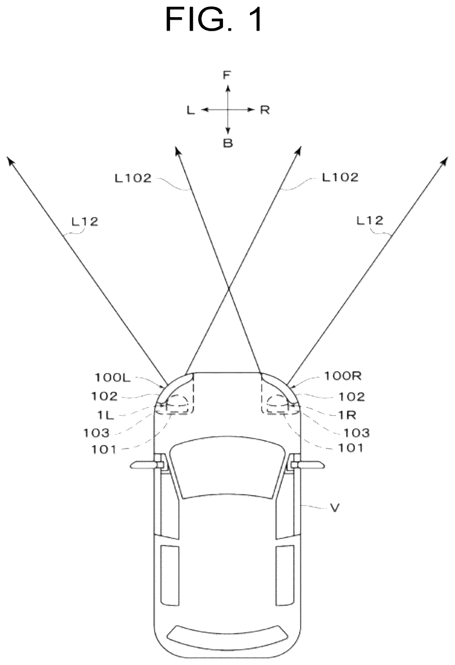
is a plan view illustrating an embodiment of a lamp unit for a vehicular headlamp and a vehicular headlamp according to the present invention in a usage state (in a state of being mounted on a vehicle).
is a traverse sectional view (a horizontal sectional view, a view taken along line II-II marked by arrows in , and a view taken along line II-II marked by arrows in ) illustrating a lamp unit of a right vehicular headlamp.
is a longitudinal sectional view (a vertical sectional view, a sectional view taken along line III-III in , and a sectional view taken along line III-III in ) illustrating the lamp unit of the right vehicular headlamp.
is a front view illustrating the lamp unit of the right vehicular headlamp in a state where a lens is removed (a view taken along line IV-IV marked by arrows in , and a view taken along line IV-IV marked by arrows in ).
is an explanatory diagram illustrating an outermost partial light distribution pattern (a first partial light distribution pattern) formed by the lamp unit of the right vehicular headlamp. A is an explanatory diagram illustrating the outermost partial light distribution pattern (the first partial light distribution pattern) on which a diffused light distribution pattern is superimposed. B is an explanatory diagram illustrating the outermost partial light distribution pattern (the first partial light distribution pattern) on which the diffused light distribution pattern is not superimposed.
C is an explanatory diagram illustrating the diffused light distribution pattern.
is an explanatory diagram illustrating a next outermost partial light distribution pattern (a second partial light distribution pattern) formed by the lamp unit of the right vehicular headlamp. A and 6 B are explanatory diagrams illustrating the next outermost partial light distribution pattern (the second partial light distribution pattern). C is an explanatory diagram illustrating a state where the light distribution pattern is not formed.
is an explanatory diagram illustrating an innermost partial light distribution pattern (a tenth partial light distribution pattern) formed by the lamp unit of the right vehicular headlamp. A is an explanatory diagram illustrating the innermost partial light distribution pattern (the tenth partial light distribution pattern) to which an additional light distribution pattern is added. B is an explanatory diagram illustrating the innermost partial light distribution pattern (the tenth partial light distribution pattern) to which the additional light distribution pattern is not added. C is an explanatory diagram illustrating the additional light distribution pattern.
is an explanatory diagram illustrating a next innermost partial light distribution pattern (a ninth partial light distribution pattern) formed by the lamp unit of the right vehicular headlamp. A and 8 B are explanatory diagrams illustrating the next innermost partial light distribution pattern (the ninth partial light distribution pattern). C is an explanatory diagram illustrating a state where the light distribution pattern is not formed.
is an explanatory diagram illustrating a high-beam light distribution pattern emitted from the lamp unit of the vehicular headlamp. A is an explanatory diagram illustrating a left high-beam light distribution pattern emitted from a lamp unit of a left vehicular headlamp. B is an explanatory diagram illustrating a right high-beam light distribution pattern emitted from the lamp unit of the right vehicular headlamp.
is an explanatory diagram illustrating an overall high-beam light distribution pattern synthesized by superimposing the left high-beam light distribution pattern (see A ) emitted from the lamp unit of the left vehicular headlamp and the right high-beam light distribution pattern (see B ) emitted from the lamp unit of the right vehicular headlamp.
is an explanatory diagram illustrating an overall high-beam light distribution pattern when an oncoming vehicle is present.
is an explanatory diagram illustrating an overall high-beam light distribution pattern when a preceding vehicle is present.
MODE FOR CARRYING OUT THE INVENTION
An example of an embodiment (example) of a lamp unit for a vehicular headlamp and a vehicular headlamp according to the present invention will be described in detail below with reference to the drawings. In the present specification and the appended claims, front, rear, up, down, left, and right refer to front, rear, up, down, left, and right when the lamp unit for a vehicular headlamp and the vehicular headlamp according to the present invention are mounted on a vehicle. In the present specification and the appended claims, an inner side of the vehicle refers to a center side in a left-right direction of the vehicle, and an outer side of the vehicle refers to a left side and a right side of the vehicle with respect to the center in the left-right direction of the vehicle.
The drawings are schematic diagrams, and thus, only main components are illustrated, and components other than the main components are not illustrated, and a part of the hatching is omitted. In to 4 , reference numeral “F” refers to “front”, reference numeral “B” refers to “rear”, reference numeral “U” refers to “up”, reference numeral “D” refers to “down”, reference numeral “L” refers to “left”, and reference numeral “R” refers to “right”. Further, in the longitudinal sectional view of , reference numerals “ 30 R”, “ 31 R”, and “LED 6 to LED 10 ” of components that are not illustrated are mentioned for the sake of convenience. Moreover, in to 12 , reference numeral “VU-VD” indicates a vertical line from top to bottom in a screen, and reference numeral “HL-HR” indicates a horizontal line from left to right in the screen. Further, in the iso-luminosity lines in to 8 , the luminosity value of the iso-luminosity line in the center is high, and the luminosity value of the iso-luminosity lines decreases toward the outside (outer periphery).
Description of Configuration of Embodiment
Configurations of lamp units 1 L and 1 R of a vehicular headlamp according to the present embodiment (hereinafter, referred to as “lamp units 1 L and 1 R”) and vehicular headlamps 100 L and 100 R of the present embodiment (hereinafter, referred to as “vehicular headlamps 100 L and 100 R”) will be described below.
(Description of Vehicular Headlamps 100 L and 100 R)
As illustrated in , a left vehicular headlamp 100 L is mounted on the left side of a front part of a vehicle V, and a right vehicular headlamp 100 R is mounted on the right side of the front part of the vehicle V.
As illustrated in , the vehicular headlamps 100 L and 100 R each include a lamp housing 101 , a lamp lens 102 , the lamp unit 1 L or 1 R, and a control device (not illustrated).
The lamp housing 101 is formed of a light-impermeable resin material. The lamp lens 102 is formed of a light-transmitting resin material. The lamp lens 102 serves as an outer lens or an outer cover. As illustrated in , the shape of the surface of the lamp lens 102 (a surface opposite to the surface on the side of a lamp chamber 103 described below) in a plan view is a slanted shape that gradually recedes from the front to the rear of the vehicle V from the inner side of the vehicle to the outer side of the vehicle, along the design surface of the vehicle V. The lamp housing 101 and the lamp lens 102 form the lamp chamber 103 . The lamp units 1 L and 1 R are arranged in the lamp chamber 103 .
(Description of Control Device)
The control device is not illustrated, but is mounted in the vehicle V. The control device includes a detection portion, a detection control portion, and a light on/off control portion.
For example, the detection portion includes an imaging device (camera) arranged in the center of an upper edge of a front windshield of the vehicle V, a millimeter wave radar arranged in the center of a front grille of the vehicle V, and the like.
The imaging device captures an image including an oncoming vehicle V 1 and a preceding vehicle V 2 relative to a host vehicle V (using the same reference numeral “V” as the vehicle). The millimeter wave radar measures the distance to the oncoming vehicle V 1 and the preceding vehicle V 2 from the host vehicle V. The detection portion outputs a detection signal to the detection control portion via an interface.
The detection control portion is an electronic control unit (ECU) for detection control, and includes an arithmetic control electronic device such as a micro-processing unit (MPU) and a central processing unit (CPU), and a storage electronic device such as a random access memory (RAM) and a read-only memory (ROM). The detection control portion calculates the position and the distance of the oncoming vehicle V 1 and the preceding vehicle V 2 , based on the detection signal from the detection portion by causing the arithmetic control electronic device to execute a predetermined program stored in the storage electronic device, and outputs a calculation signal to the light on/off control portion via the interface.
The light on/off control portion is an ECU that executes control for turning the light on and off, and includes an arithmetic control electronic device such as an MPU and a CPU, and an electronic storage device such as a RAM and a ROM. The light on/off control portion causes the arithmetic control electronic device to execute a predetermined program stored in the storage electronic device, to perform control for turning on and off, and increasing or decreasing the light intensity of a plurality of light-emitting elements (in the present example, ten light-emitting elements LED 1 to LED 10 ) described later, based on the calculation signal from the detection control portion.
(Description of Lamp Units 1 L and 1 R)
The left lamp unit 1 L of the left vehicular headlamp 100 L emits a left high-beam light distribution pattern PL to the front of the vehicle V, as illustrated in A . The right lamp unit 1 R of the right vehicular headlamp 100 R emits a right high-beam light distribution pattern PR to the front of the vehicle V, as illustrated in B .
The left high-beam light distribution pattern PL and the right high-beam light distribution pattern PR are superimposed to form an overall high-beam light distribution pattern P, as illustrated in . In the present example, the overall high-beam light distribution pattern P is a wide high-beam light distribution pattern that illuminates a wide range from an area near the front of the vehicle V to an area far from the vehicle V with high luminous intensity.
The lamp units 1 L and 1 R are lamp units having variable light distribution, and are so-called Adaptive Driving Beam (ADB) type lamp units. When there is no vehicle such as the oncoming vehicle V 1 and the preceding vehicle V 2 in front, the lamp units 1 L and 1 R emit the overall high-beam light distribution pattern P illustrated in . On the other hand, when a vehicle is present in front, the lamp units 1 L and 1 R perform control so that an area in which the vehicle is present (an area illustrated by dashed lines in ) is darker than surrounding areas (areas illustrated by solid lines in ).
That is, the lamp units 1 L and 1 R cause the control device to perform control for turning on or off, and increasing or decreasing the light intensity of the light-emitting elements LED 1 to LED 10 of a light source 2 described below, to turn off or decrease the light intensity of a partial light distribution pattern described below in which a vehicle is present in front, to change the overall high-beam light distribution pattern P.
(Description of Right Lamp Unit 1 R)
The right lamp unit 1 R will be described below with reference to to 4 . Here, in the right lamp unit 1 R, the outer side of the vehicle is the right side of the vehicle V and the inner side of the vehicle is the left side of the vehicle V, and hereinafter, the “outer side of the vehicle” will be referred to as the “right side” and the “inner side of the vehicle” will be referred to as the “left side”. On the other hand, in the left lamp unit 1 L, the outer side of the vehicle is the left side of the vehicle V and the inner side of the vehicle is the right side of the vehicle V, and hereinafter, the “outer side of the vehicle” will be referred to as the “left side” and the “inner side of the vehicle” will be referred to as the “right side”.
The left lamp unit 1 L has a configuration that is substantially similar to the configuration of the right lamp unit 1 R, but in which the left side and the right side are reversed. Therefore, the description of the left lamp unit 1 L and illustrations similar to those in to 4 will be omitted. Further, the expressions “left and right sides”, “left side”, and “right side” will be omitted as appropriate.
The lamp unit 1 R includes a light source 2 , a reflector 3 , a lens 4 , a heat sink 5 , and a fan unit 6 . The light source 2 , the reflector 3 , the lens 4 , the heat sink 5 , and the fan unit 6 are attached to a frame member (not illustrated), and are also attached to the lamp housing 101 via a frame member and a bracket member (not illustrated).
(Description of Light Source 2 )
As illustrated in to 4 , the light source 2 includes a plurality of light-emitting elements, in the present example, ten light-emitting elements LED 1 , LED 2 , LED 3 , LED 4 , LED 5 , LED 6 , LED 7 , LED 8 , LED 9 , and LED 10 (hereinafter, referred to as “LED 1 to LED 10 ”), and a substrate 20 . Here, the ten light-emitting elements LED 1 to LED 10 are referred to as a first light-emitting element LED 1 to a tenth light-emitting element LED 10 from the left.
That is, among the ten light-emitting elements LED 1 to LED 10 , a light-emitting element located at a leftmost position (on the inner side of the vehicle) (an innermost light-emitting element described in the claims) is the first light-emitting element LED 1 . A light-emitting element located in an adjacent position to the right of the first light-emitting element LED 1 (a next innermost light-emitting element described in the claims) is a second light-emitting element LED 2 . Among the ten light-emitting elements LED 1 to LED 10 , a light-emitting element located at the rightmost position (on the outer side of the vehicle) (an outermost light-emitting element described in the claims) is the tenth light-emitting element LED 10 . The light-emitting element located in an adjacent position to the left of the tenth light-emitting element LED 10 (a next outermost light-emitting element described in the claims) is a ninth light-emitting element LED 9 .
In the present example, the ten light-emitting elements LED 1 to LED 10 form an LED array, and are arrayed in the horizontal direction from left to right on one surface (front surface) of the substrate 20 . The light-emitting surfaces of the ten light-emitting elements LED 1 to LED 10 each have a rectangular shape. The above-mentioned control device performs control for turning on or off, and increasing or decreasing the light intensity of the ten light-emitting elements LED 1 to LED 10 . The other surface (rear surface) of the substrate 20 is attached to an attachment portion 50 of the heat sink 5 .
The light (radiated light, emitted light) emitted from the light-emitting surfaces of the ten light-emitting elements LED 1 to LED 10 has a Lambertian shape. As a result, light from the light-emitting elements LED 1 to LED 10 is emitted to the front of the vehicle V in a wide range including upward, downward, left, and right.
As a result, a large part of the light from the light-emitting elements LED 1 to LED 10 is incident as direct light on a later-described incident surface 40 of the lens 4 . Further, light from a lower part of the light-emitting elements LED 1 to LED 10 is reflected by a later-described reflecting surface 30 of the reflector 3 and is incident as reflected light on the incident surface 40 of the lens 4 .
Further, light L 1 and L 2 from left parts of the first light-emitting element LED 1 and the second light-emitting element LED 2 are incident on a later-described inner reflecting surface 30 L of the reflector 3 , as illustrated in . Moreover, light (not illustrated) from left parts of the third light-emitting element LED 3 to the tenth light-emitting element LED 10 is also incident on the inner reflecting surface 30 L of the reflector 3 , which will be described later.
On the other hand, light L 9 and L 10 from right parts of the ninth light-emitting element LED 9 and the tenth light-emitting element LED 10 is incident on a later-described outer reflecting surface 30 R of the reflector 3 , as illustrated in . Further, light (not illustrated) from right parts of the first light-emitting element LED 1 to the eighth light-emitting element LED 8 is also incident on the outer reflecting surface 30 R of the reflector 3 , which will be described later.
(Description of Reflector 3 )
The reflector 3 is arranged between the light source 2 and the lens 4 . The reflector 3 includes a main body portion 31 and attachment portions 31 L and 31 R provided integrally on the left and right sides of the main body portion 31 . The main body portion 31 is arranged below the light-emitting elements LED 1 to LED 10 . The left attachment portion 31 L is arranged to the left of the light-emitting elements LED 1 to LED 10 . The right attachment portion 31 R is arranged to the right of the light-emitting elements LED 1 to LED 10 . The left and right attachment portions 31 L and 31 R are attached to the attachment portion 50 of the heat sink 5 .
The reflecting surface 30 is provided on an upper surface of the main body portion 31 . The reflecting surface 30 may be, for example, the reflecting surface described in JP 2017-195116 A. The reflecting surface 30 reflects the light from the lower part of the light-emitting elements LED 1 to LED 10 that is not incident on an effective portion of the incident surface 40 of the lens 4 , onto the incident surface 40 of the lens 4 , to irradiate the incident surface 40 with the light. Thus, the light from the light-emitting elements LED 1 to LED 10 can be utilized effectively.
(Description of Inner Reflecting Surface 30 L)
The inner reflecting surface 30 L is provided as a side reflector at an upper end part of the left attachment portion 31 L. The inner reflecting surface 30 L is provided to the left from the ten light-emitting elements LED 1 to LED 10 . That is, the inner reflecting surface 30 L is provided to the left (to the inner side of the vehicle) from the first light-emitting element LED 1 . The inner reflecting surface 30 L is provided in front of the light-emitting elements LED 1 to LED 10 . Further, in the present example, the inner reflecting surface 30 L is formed by any surface, such as a freeform surface, a plurality of curved surfaces, one curved surface, a plurality of flat surfaces, and one flat surface.
As indicated by a solid arrow in , among the light from the first light-emitting element LED 1 , the light L 1 from the left part of the first light-emitting element LED 1 is incident on the inner reflecting surface 30 L. As indicated by a solid arrow in , the inner reflecting surface 30 L reflects the incident light L 1 from the first light-emitting element LED 1 as reflected light L 11 onto the incident surface 40 of the lens 4 . Among the incident surface 40 of the lens 4 , the reflected light L 11 is incident on an effective portion, which is left from an optical axis Z and above the optical axis Z. The reflected light L 11 that is incident on the lens 4 is irradiated from the lens 4 to the front of the vehicle V in diffused light distribution patterns PL 1 C and PR 1 C described below.
As indicated by a dashed arrow in , among the light from the second light-emitting element LED 2 , the light L 2 from the left part of the second light-emitting element LED 2 is incident on the inner reflecting surface 30 L. As indicated by a dashed arrow in , the inner reflecting surface 30 L reflects the incident light from the second light-emitting element LED 2 as reflected light L 21 to an area above the optical axis Z and outside the effective portion of the incident surface 40 , that is, outside a diagonally upper right side of the lens 4 . Therefore, the reflected light L 21 that is emitted from the second light-emitting element LED 2 and reflected by the inner reflecting surface 30 L is not incident on the lens 4 , and thus, does not affect a left vertical cutoff line CL 2 L and a right vertical cutoff line CL 2 R of second partial light distribution patterns PL 2 and PR 2 described later.
Further, light from left parts of the third light-emitting element LED 3 to the tenth light-emitting element LED 10 is also incident on the inner reflecting surface 30 L. However, the light from the third light-emitting element LED 3 to the tenth light-emitting element LED 10 is light from the second light-emitting element LED 2 and thus, is not incident on the lens 4 , similarly to the reflected light L 21 reflected by the inner reflecting surface 30 L. Moreover, the light from the third light-emitting element LED 3 to the tenth light-emitting element LED 10 is weak and thus, does not affect the left vertical cutoff line and the right vertical cutoff line of third partial light distribution patterns PL 3 and PR 3 to tenth partial light distribution patterns PL 10 and PL 10 described below. Therefore, even if the light from the third light-emitting element LED 3 to the tenth light-emitting element LED 10 is incident on the lens 4 , the light does not affect the left vertical cutoff line and the right vertical cutoff line.
(Description of Outer Reflecting Surface 30 R)
The outer reflecting surface 30 R is provided as a side reflector at the upper end part of the right attachment portion 31 R. The outer reflecting surface 30 R is provided to the right from the ten light-emitting elements LED 1 to LED 10 . That is, the outer reflecting surface 30 R is provided to the right (the outer side of the vehicle) from the tenth light-emitting element LED 10 . The outer reflecting surface 30 R is provided toward the front from the light-emitting elements LED 1 to LED 10 . Further, in the present example, the outer reflecting surface 30 R is formed by an ellipsoidal surface that extends in the up-down direction and in which a first focal point F 1 is located at the tenth light-emitting element LED 10 and a second focal point F 2 is located to the left of the optical axis Z on the incident surface 40 of the lens 4 .
As indicated by a solid arrow in , among the light from the tenth light-emitting element LED 10 , light L 10 from the right part of the tenth light-emitting element LED 10 is incident on the outer reflecting surface 30 R. As indicated by a solid arrow in , the outer reflecting surface 30 R reflects the incident light L 10 from the tenth light-emitting element LED 10 as reflected light L 101 onto the incident surface 40 of the lens 4 . Among the incident surface 40 of the lens 4 , the reflected light L 101 is mainly incident on an effective portion of the incident surface 40 of the lens 4 , which is located left from the optical axis Z and right from the reflected light L 11 from the inner reflecting surface 30 L formed by the light L 1 from the first light-emitting element LED 1 . The reflected light L 101 incident on the lens 4 is emitted from the lens 4 to the front of the vehicle V as additional light distribution patterns PL 10 C and PR 10 C described below.
As indicated by a dashed arrow in , among the light from the ninth light-emitting element LED 9 , light L 9 from a right part of the ninth light-emitting element LED 9 is incident on the outer reflecting surface 30 R. As indicated by a dashed arrow in , the outer reflecting surface 30 R reflects the light L 9 from the ninth light-emitting element LED 9 as reflected light L 91 to the left side to an area outside of the effective portion of the incident surface 40 , that is, outward to the left side of the lens 4 . Therefore, the reflected light L 91 that is emitted from the ninth light-emitting element LED 9 and reflected by the outer reflecting surface 30 R is not incident on the lens 4 , and thus, does not affect the overall high-beam light distribution pattern P.
Further, light from right parts of the first light-emitting element LED 1 to the eighth light-emitting element LED 8 is incident on the outer reflecting surface 30 R. However, the light from the right parts of the first light-emitting element LED 1 to the eighth light-emitting element LED 8 is weak and thus, does not affect the overall high-beam light distribution pattern P. Therefore, the light from the first light-emitting element LED 1 to the eighth light-emitting element LED 8 does not affect the overall high-beam light distribution pattern P.
(Description of Lens 4 )
As illustrated in , in the present example, the lens 4 is a projection lens, and is formed by an aspheric lens. The lens 4 includes the incident surface 40 , an emitting surface 41 , and the optical axis Z. In the present example, the optical axis Z passes at a position between the sixth light-emitting element LED 6 and the seventh light-emitting element LED 7 , as illustrated in .
The lens 4 controls the light from the ten light-emitting elements LED 1 to LED 10 for each of the ten light-emitting elements LED 1 to LED 10 , and emits the light to the front of the vehicle V in a plurality of partial light distribution patterns, in the example, ten partial light distribution patterns PL 1 to PL 10 and PR 1 to PR 10 (see ). Here, in the present example, the light from the ten light-emitting elements LED 1 to LED 10 includes direct light from the ten light-emitting elements LED 1 to LED 10 and reflected light that is light from the ten light-emitting elements LED 1 to LED 10 which is reflected by the reflecting surface 30 . The ten partial light distribution patterns PL 1 to PL 10 and PR 1 to PR 10 will be described in detail later.
The lens 4 controls the light L 1 from the first light-emitting element LED 1 , that is, the reflected light L 11 from the inner reflecting surface 30 L, and emits the reflected light L 11 toward the front of the vehicle V as emitted light L 12 (see the solid arrow in ), that is, as diffused light distribution patterns PL 1 C and PR 1 C (see C and 9 ). The diffused light distribution patterns PL 1 C and PR 1 C will be described in detail later, similarly to the ten partial light distribution patterns. The light L 2 from the second light-emitting element LED 2 , that is, the reflected light L 21 from the inner reflecting surface 30 L passes outside the lens 4 and thus, does not form a light distribution pattern as illustrated in C .
Further, the lens 4 controls the light L 10 from the tenth light-emitting element LED 10 , that is, the reflected light L 101 from the outer reflecting surface 30 R, and emits the reflected light L 101 toward the front of the vehicle V as emitted light L 102 (see the dashed arrow in ), that is, as the additional light distribution patterns PL 10 C and PR 10 C (see C and 9 ). The additional light distribution patterns PL 10 C and PR 10 C will be described in detail later, similarly to the ten partial light distribution patterns and the diffused light distribution patterns PL 1 C and PR 1 C. The light L 9 from the ninth light-emitting element LED 9 , that is, the reflected light L 91 from the outer reflecting surface 30 R passes outside the lens 4 and thus, does not form a light distribution pattern as illustrated in C .
The incident surface 40 is an aspheric surface, in the present example, an aspheric surface close to a plane, and controls the light from each of the ten light-emitting elements LED 1 to LED 10 within the lens 4 as incident light (not illustrated). The emitting surface 41 is an aspheric surface, in the present example, an aspheric surface close to a sphere, and controls the incident light from each of the ten light-emitting elements LED 1 to LED 10 that is incident on the incident surface 40 , to be emitted as emitted light (not illustrated) to the outside, that is, toward the front of the vehicle V.
As described above, the incident surface 40 and the emitting surface 41 of the lens 4 are designed and formed, based on the light distribution of the ten partial light distribution patterns PL 1 to PL 10 and PR 1 to PR 10 , the diffused light distribution pattern PR 1 C, and the additional light distribution pattern PR 10 C, which will be described below.
The front shape of the lens 4 (the front shape of the emitting surface 41 ) is a horizontally elongated shape that has a narrow vertical width (up-down width) and a wide horizontal width (left-right width). The thickness of the lens 4 is thicker at a center part and decreases gradually from the center part to a peripheral part. Further, the radius of curvature of the incident surface 40 is greater than the radius of curvature of the emitting surface 41 . That is, the lens 4 of the lamp units 1 L and 1 R of ADB type needs to cause light from the ten light-emitting elements LED 1 to LED 10 to be incident on the incident surface 40 and emitted toward the front of the vehicle V from the emitting surface 41 . Therefore, the radius of curvature of the incident surface 40 is large, and the radius of curvature of the emitting surface 41 is small.
(Description of Light Distribution Patterns)
The light distribution patterns emitted from the left and right lamp units 1 L and 1 R will be described below with reference to to 12 .
As illustrated in A , the left lamp unit 1 L of the left vehicular headlamp 100 L emits the ten partial light distribution patterns PL 1 to PL 10 (PL 1 , PL 2 , PL 3 , PL 4 , PL 5 , PL 6 , PL 7 , PL 8 , PL 9 , and PL 10 ), the diffused light distribution pattern PL 1 C, and the additional light distribution pattern PL 10 C as the left high-beam light distribution pattern PL toward the front of the vehicle V. Here, the ten partial light distribution patterns PL 1 to PL 10 are referred to as the first partial light distribution pattern PL 1 to the tenth partial light distribution pattern PL 10 , starting from the left side.
On the other hand, as illustrated in to 8 and 9 B , the right lamp unit 1 R of the right vehicular headlamp 100 R emits the ten partial light distribution patterns PR 1 to PR 10 (PR 1 , PR 2 , PR 3 , PR 4 , PR 5 , PR 6 , PR 7 , PR 8 , PR 9 , and PR 10 ), the diffused light distribution pattern PR 1 C, and the additional light distribution pattern PR 10 C as the right high-beam light distribution pattern PR toward the front of the vehicle V. Here, the ten partial light distribution patterns PR 1 to PR 10 are referred to as the first partial light distribution pattern PR 1 to the tenth partial light distribution pattern PR 10 , starting from the right side.
The left high-beam light distribution pattern PL and the right high-beam light distribution pattern PR emitted from the left and right lamp units 1 L and 1 R are superimposed to form the overall high-beam light distribution pattern P, as illustrated in to 12 . In the overall high-beam light distribution pattern P, the left part of the left high-beam light distribution pattern PL is diffused further left than the left part of the right high-beam light distribution pattern PR, and the right part of the right high-beam light distribution pattern PR is diffused further right than the right part of the left high-beam light distribution pattern PL.
Note that the shapes of the ten partial light distribution patterns PL 1 to PL 10 and PR 1 to PR 10 , the shapes of the diffused light distribution patterns PL 1 C and PR 1 C, and the shapes of the additional light distribution patterns PL 10 C and PR 10 C are not limited to the shapes illustrated in to 12 .
(Description of Ten Partial Light Distribution Patterns PL 1 to PL 10 and PR 1 to PR 10 )
As described above, the ten partial light distribution patterns PL 1 to PL 10 and PR 1 to PR 10 are formed by using the lens 4 to control the light from the ten light-emitting elements LED 1 to LED 10 (direct light from the ten light-emitting elements LED 1 to LED 10 and light from the ten light-emitting elements LED 1 to LED 10 ).
That is, the ten partial light distribution patterns PL 1 to PL 10 and PR 1 to PR 10 are formed from projected images of the light-emitting surfaces of the ten light-emitting elements LED 1 to LED 10 illuminated by the lens 4 , and correspond one-to-one to corresponding ones of the ten light-emitting elements LED 1 to LED 10 . The ten partial light distribution patterns PL 1 to PL 10 and PR 1 to PR 10 are arrayed in the horizontal direction from left to right.
The control for turning on or off, and increasing or decreasing the light intensity of the ten partial light distribution patterns PL 1 to PL 10 and PR 1 to PR 10 is performed based on the control for turning on or off, and increasing or decreasing the light intensity of each of the ten light-emitting elements LED 1 to LED 10 performed by the control device. Thus, the ten partial light distribution patterns PL 1 to PL 10 and PR 1 to PR 10 have high resolution in the overall high-beam light distribution pattern P.
(Description of Vertical Cutoff Line)
The left vertical cutoff line and the right vertical cutoff line are respectively formed at the left end and the right end of the ten partial light distribution patterns PL 1 to PL 10 and PR 1 to PR 10 . For example, as illustrated in B and 9 B , a left vertical cutoff line CL 1 L and a right vertical cutoff line CL 1 R are formed on the left and right ends of the first partial light distribution pattern PR 1 on the right side. As illustrated in A, 6 B, and 9 B , a left vertical cutoff line CL 2 L and a right vertical cutoff line CL 2 R are formed on the left and right ends of the second partial light distribution pattern PR 2 on the right side. Further, as illustrated in B and 9 B , a left vertical cutoff line CL 10 L and a right vertical cutoff line CL 10 R are formed on the left and right ends of the tenth partial light distribution pattern PR 10 on the right side. Moreover, as illustrated in A, 8 B, and 9 B , a left vertical cutoff line CL 9 L and a right vertical cutoff line CL 9 R are formed on the left and right ends of the ninth partial light distribution pattern PR 9 on the right side.
The left vertical cutoff lines and the right vertical cutoff lines are provided to prevent an adjacent bright area (the partial light distribution patterns PL 7 , PR 6 , and PR 1 illustrated by solid lines in , and the partial light distribution patterns PL 4 , PR 8 , PL 9 , and PR 4 illustrated by solid lines in ) from glaring onto a preceding vehicle when an area where the vehicle in front is present (the partial light distribution patterns PL 8 to PL 10 , PR 2 to PR 5 , and PL 10 C illustrated by dashed lines in , and the partial light distribution patterns PL 5 to PL 8 and PR 5 to PR 8 illustrated by dashed lines in ) is darker than the surrounding area (the partial light distribution patterns illustrated by solid lines in ). Thus, the left vertical cutoff lines and the right vertical cutoff lines of the ten partial light distribution patterns PL 1 to PL 10 and PR 1 to PR 10 are formed with high precision and controlled with high precision by the lens 4 .
(Description of Diffused Light Distribution Patterns PL 1 C and PR 1 C)
As illustrated in to 12 , the diffused light distribution patterns PL 1 C and PR 1 C are formed by using the lens 4 to control the light L 1 from the first light-emitting element LED 1 , that is, the reflected light L 11 reflected by the inner reflecting surface 30 L. The diffused light distribution patterns PL 1 C and PR 1 C are superimposed on the first partial light distribution patterns PL 1 and PR 1 on the outer side of the vehicle among the ten partial light distribution patterns PL 1 to PL 10 and PR 1 to PR 10 .
An edge of the diffused light distribution patterns PL 1 C and PR 1 C on the outer side of the vehicle, in the present example, a vertical cutoff line CL 1 RC on the outer side of the vehicle (see C and 9 B ), is located further to the outer side (the right side) of the vehicle than an edge of the first partial light distribution patterns PL 1 and PR 1 on the outer side of the vehicle, in the present example, the vertical cutoff line CL 1 R on the outer side of the vehicle (see C and 9 B ).
Thus, an edge on the outer side of the vehicle of the first partial light distribution patterns PL 1 A and PR 1 A onto which the diffused light distribution patterns PL 1 C and PR 1 C are superimposed (hereinafter, referred to as “superimposed first partial light distribution patterns PL 1 A and PR 1 A”), in the present example, the vertical cutoff line CL 1 RC on the outer side of the vehicle (see A and 9 B ), is located further to the outer side (the right side) of the vehicle than an edge on the outer side of the vehicle of the first partial light distribution patterns PL 1 and PR 1 onto which the diffused light distribution patterns PL 1 C and PR 1 C are not superimposed (hereinafter, referred to as “first partial light distribution patterns PL 1 and PR 1 before superposition”), in the present example, the vertical cutoff line CL 1 R on the outer side of the vehicle (see B and 9 B ).
Therefore, a portion of the superimposed first partial light distribution patterns PL 1 A and PR 1 A on the outer side of the vehicle (see A and 9 B ) is diffused further outward from the vehicle than a portion of the first partial light distribution patterns PL 1 and PR 1 before superposition on the outer side of the vehicle (see B and 9 B ).
The area of the diffused light distribution patterns PL 1 C and PR 1 C is narrower than the area of the first partial light distribution patterns PL 1 A and PR 1 A. Thus, an edge of the diffused light distribution patterns PL 1 C and PR 1 C on the inner side of the vehicle (see C and 9 B ), is located further to the outer side (the right side) of the vehicle than an edge of the first partial light distribution patterns PL 1 and PR 1 on the inner side of the vehicle, in the present example, the vertical cutoff line CL 1 L on the inner side of the vehicle (see B and 9 B ).
Therefore, the vertical cutoff line CL 1 L on the inner side of the vehicle of the superimposed first partial light distribution patterns PL 1 A and PR 1 A (see A and 9 B ) and the vertical cutoff line CL 1 L on the inner side of the vehicle of the first partial light distribution patterns PL 1 and PR 1 before superposition (see B and 9 B ) are identical or substantially identical.
(Description of Additional Light Distribution Patterns PL 10 C and PR 10 C)
As illustrated in to 12 , the additional light distribution patterns PL 10 C and PR 10 C are formed by using the lens 4 to control the light L 10 from the tenth light-emitting element LED 10 , that is, the reflected light L 101 reflected by the outer reflecting surface 30 R.
The additional light distribution patterns PL 10 C and PR 10 C are superimposed on the inner side of the vehicle of the tenth partial light distribution patterns PL 10 and PR 10 . That is, the additional light distribution pattern PL 10 C on the left side is superimposed on the right side, that is, the inner side of the vehicle of the tenth partial light distribution pattern PL 10 on the left side, as illustrated in A , and the additional light distribution pattern PR 10 C on the right side is superimposed on the left side, that is, the inner side of the vehicle, of the tenth partial light distribution pattern PR 10 on the right side, as illustrated in B .
Therefore, the luminous intensity of tenth partial light distribution patterns PL 10 A and PR 10 A onto which the additional light distribution patterns PL 10 C and PR 10 C are superimposed (hereinafter, referred to as “superimposed tenth partial light distribution patterns PL 10 A and PR 10 A”, see A ) is higher than the luminous intensity of the tenth partial light distribution patterns PL 10 and PR 10 onto which the additional light distribution patterns PL 10 C and PR 10 C are not superimposed (hereinafter, referred to as “tenth partial light distribution patterns PL 10 and PR 10 before superposition”, see B ).
Further, a vertical cutoff line CL 10 LC on the inner side of the vehicle of the additional light distribution patterns PL 10 C and PR 10 C (see C and 9 B ) is located slightly more to the inner side of the vehicle than the vertical cutoff line CL 10 L on the inner side of the vehicle of the tenth partial light distribution patterns PL 10 and PR 10 (see B and 9 B ). Thus, a portion of the additional light distribution patterns PL 10 C and PR 10 C on the inner side of the vehicle is located slightly more to the inner side of the vehicle than a portion of the tenth partial light distribution patterns PL 10 and PR 10 on the inner side of the vehicle. Therefore, a portion of the superimposed tenth partial light distribution patterns PL 10 A and PR 10 A on the inner side of the vehicle (see A and 9 B ) is slightly more diffused toward the inner side of the vehicle than a portion of the tenth partial light distribution patterns PL 10 and PR 10 before superposition on the inner side of the vehicle (see B and 9 B ).
The diffusion width of the part of the superimposed tenth partial light distribution patterns PL 10 A and PR 10 A on the inner side of the vehicle is narrower than the diffusion width of the part of the superimposed first partial light distribution patterns PL 1 A and PR 1 A on the outer side of the vehicle. Further, the vertical cutoff line CLIOR on the outer side of the vehicle of the superimposed tenth partial light distribution patterns PL 10 A and PR 10 A and the vertical cutoff line CLIOR on the outer side of the vehicle of the tenth partial light distribution patterns PL 10 and PR 10 before superposition are identical or substantially identical.
(Description of Heat Sink 5 )
The heat sink 5 is formed of a member having high thermal conductivity, in the present example, a member formed from aluminum by die-casting. As illustrated in to 4 , the heat sink 5 is formed by an integral structure including the attachment portion 50 having a plate shape and a heat dissipating portion 51 having a shape including fins.
The light-emitting elements LED 1 to LED 10 are attached via the substrate 20 to an attachment surface on the front surface of the attachment portion 50 , and the attachment portions 31 L and 31 R of the reflector 3 are also attached to the attachment portion 50 . The front surface of the heat dissipating portion 51 is integrally provided on the rear surface of the attachment portion 50 . The plurality of fins of the heat dissipating portion 51 are parallel or substantially parallel in the up-down direction.
(Description of Fan Unit 6 )
As illustrated in to 4 , the fan unit 6 is attached to the rear surface of the heat dissipating portion 51 of the heat sink 5 . The fan unit 6 forcibly and directly blows air onto the heat sink 5 , and thus, cools the heat sink 5 from the heat generated in the light-emitting elements LED 1 to LED 10 .
Description of Operation of Embodiment
The lamp units 1 L and 1 R according to the present embodiment and the vehicular headlamps 100 L and 100 R according to the present embodiment are configured as described above, and an operation of the lamp units 1 L and 1 R and the vehicular headlamps 100 L and 100 R will be described below.
(Description of Case without Vehicle in Front Such as Oncoming Vehicle V 1 and Preceding Vehicle V 2 )
As illustrated in , when there is no vehicle in front such as the oncoming vehicle V 1 and the preceding vehicle V 2 , the detection portion of the control device does not detect a vehicle in front such as the oncoming vehicle V 1 and the preceding vehicle V 2 . Thus, all of the ten left and right light-emitting elements LED 1 to LED 10 of the left and right lamp units 1 L and 1 R light up.
Subsequently, light from each of the ten light-emitting elements LED 1 to LED 10 of the left and right lamp units 1 L and 1 R is incident on the incident surface 40 of the lens 4 as direct light or as reflected light from the reflecting surface 30 . The light from each of the ten light-emitting elements LED 1 to LED 10 that is incident on the lens 4 passes through the emitting surface 41 of the lens 4 and is emitted toward the front of the vehicle V as the ten left and right partial light distribution patterns PL 1 to PL 10 and PR 1 to PR 10 , as illustrated in to 12 .
Further, a part of the light L 1 from the first light-emitting element LED 1 is reflected by the outer reflecting surface 30 R, and the reflected light L 11 passes through the lens 4 and is emitted. Subsequently, the emitted light L 12 is emitted toward the front of the vehicle V as the left and right diffused light distribution patterns PL 1 C and PR 1 C, as illustrated in to 12 .
Moreover, a part of the light L 10 from the tenth light-emitting element LED 10 is reflected by the inner reflecting surface 30 L, and the reflected light L 101 passes through the lens 4 and is emitted. Subsequently, the emitted light L 102 is emitted toward the front of the vehicle V as the left and right additional light distribution patterns PL 10 C and PR 10 C, as illustrated in to 12 .
The ten left and right partial light distribution patterns PL 1 to PL 10 and PR 1 to PR 10 , the left and right diffused light distribution patterns PL 1 C and PR 1 C, and the left and right additional light distribution patterns PL 10 C and PR 10 C are superimposed to form the left and right high-beam light distribution patterns PL and PR illustrated in to 12 . The left and right high-beam light distribution patterns PL and PR are superimposed on each other to form the overall high-beam light distribution pattern P illustrated in to 12 .
(Description of Case where Oncoming Vehicle V 1 is Present)
As illustrated in , when the oncoming vehicle V 1 is present, the detection portion of the control device detects the oncoming vehicle V 1 . Therefore, among the ten light-emitting elements LED 1 to LED 10 in the left and right lamp units 1 L and 1 R, the light-emitting elements that illuminate the area where the oncoming vehicle V 1 is present, in the present example, the light-emitting elements LED 8 to LED 10 of the left lamp unit 1 L and the light-emitting elements LED 2 to LED 5 of the right lamp unit 1 R, are turned off or decreased in light intensity by the control of the control device.
Subsequently, among the ten left and right partial light distribution patterns PL 1 to PL 10 and PR 1 to PR 10 , the left and right diffused light distribution patterns PL 1 C and PR 1 C, and the left and right additional light distribution patterns PL 10 C and PR 10 C, the left partial light distribution patterns PL 8 to PL 10 and PL 10 C and the right partial light distribution patterns PR 2 to PR 5 respectively corresponding to the light-emitting elements LED 8 to LED 10 of the turned-off left lamp unit 1 L and the light-emitting elements LED 2 to LED 5 of the turned-off right lamp unit 1 R are turned off or decreased in light intensity, as illustrated by the dashed lines in . As a result, in the overall high-beam light distribution pattern P illustrated in , the area where the oncoming vehicle V 1 is present is darker than surrounding areas thereof, and no dazzling light is emitted toward the oncoming vehicle V 1 .
(Description of Case where Preceding Vehicle V 2 is Present)
As illustrated in , when the preceding vehicle V 2 is present, the detection portion of the control device detects the preceding vehicle V 2 . Therefore, among the ten light-emitting elements LED 1 to LED 10 in the left and right lamp units 1 L and 1 R, the light-emitting elements that illuminate the area where the preceding vehicle V 2 is present, in the present example, the light-emitting elements LED 5 to LED 8 of the left lamp unit 1 L and the light-emitting elements LED 5 to LED 8 of the right lamp unit 1 R, are turned off or decreased in light intensity by the control of the control device.
Subsequently, among the ten left and right partial light distribution patterns PL 1 to PL 10 and PR 1 to PR 10 , the left and right diffused light distribution patterns PL 1 C and PR 1 C, and the left and right additional light distribution patterns PL 10 C and PR 10 C, the left partial light distribution patterns PL 5 to PL 8 and the right partial light distribution patterns PR 5 to PR 8 respectively corresponding to the light-emitting elements LED 5 to LED 8 of the turned-off left lamp unit 1 L and the light-emitting elements LED 5 to LED 8 of the turned-off right lamp unit 1 R, are turned off or decreased in light intensity, as illustrated by the dashed lines in . As a result, in the overall high-beam light distribution pattern P illustrated in , the area where the preceding vehicle V 2 is present is darker than surrounding areas thereof, and no dazzling light is emitted toward the preceding vehicle V 2 .
(Description of Cooling)
Heat generated in the light-emitting elements LED 1 to LED 10 is dissipated to the outside via the substrate 20 and the heat sink 5 that serves as an attachment member. The heat sink 5 is cooled by the fan unit 6 by using forced air cooling.
(Description of Effects of Embodiment)
The lamp units 1 L and 1 R according to the present embodiment and the vehicular headlamps 100 L and 100 R according to the present embodiment (hereinafter, referred to as “lamp systems 1 L, 1 R, 100 L, and 100 R”) have the above-described configuration and operation, and the effects thereof will be described below.
In the lamp systems 1 L, 1 R, 100 L, and 100 R, the light L 1 from the first light-emitting element LED 1 , which is located furthest to the inner side of the vehicle among the ten light-emitting elements LED 1 to LED 10 , is reflected onto the lens 4 as the reflected light L 11 by the inner reflecting surface 30 L, which is located further to the inner side of the vehicle than the ten light-emitting elements LED 1 to LED 10 .
Further, the lamp systems 1 L, 1 R, 100 L, and 100 R use the lens 4 arranged in front of the light source 2 including the ten light-emitting elements LED 1 to LED 10 to emit the light from the ten light-emitting elements LED 1 to LED 10 toward the front of the vehicle V as the ten partial light distribution patterns PL 1 to PL 10 and PR 1 to PR 10 arrayed in the horizontal direction from left to right.
Moreover, the lamp systems 1 L, 1 R, 100 L, and 100 R use the lens 4 to emit the reflected light L 11 from the inner reflecting surface 30 L toward the front of the vehicle V as the diffused light distribution patterns PL 1 C and PR 1 C, so that the diffused light distribution patterns PL 1 C and PR 1 C are superimposed on the first partial light distribution patterns PL 1 and PR 1 which are located furthest on the outer side of the vehicle among the ten partial light distribution patterns PL 1 to PL 10 and PR 1 to PR 10 , and so that an edge of the diffused light distribution patterns PL 1 C and PR 1 C on the outer side of the vehicle (the vertical cutoff line CL 1 RC on the outer side of the vehicle) is located further on the outer side of the vehicle than an edge of the first partial light distribution patterns PL 1 and PR 1 on the outer side of the vehicle (the vertical cutoff line CL 1 R on the outer side of the vehicle).
Thus, in the lamp systems 1 L, 1 R, 100 L, and 100 R, the edge of the superimposed first partial light distribution patterns PL 1 A and PR 1 A (the first partial light distribution patterns PL 1 A and PR 1 A onto which the diffused light distribution patterns PL 1 C and PR 1 C are superimposed) on the outer side of the vehicle (the vertical cutoff line CL 1 RC on the outer side of the vehicle), can be positioned further to the outer side of the vehicle than the edge of the first partial light distribution patterns PL 1 and PR 1 before superposition (the first partial light distribution patterns PL 1 and PR 1 onto which the diffused light distribution patterns PL 1 C and PR 1 C are not superimposed) on the outer side of the vehicle (the vertical cutoff line CL 1 R on the outer side of the vehicle).
Therefore, the lamp systems 1 L, 1 R, 100 L, and 100 R can diffuse a portion of the superimposed first partial light distribution patterns PL 1 A and PR 1 A on the outer side of the vehicle further to an outer side of the vehicle than a portion on the outer side of the vehicle of the first partial light distribution patterns PL 1 and PR 1 before superposition.
As described above, the lamp systems 1 L, 1 R, 100 L, and 100 R can diffuse the left and right sides of the overall high-beam light distribution pattern P on the outer side of the vehicle further to the left and right sides on the outer side of the vehicle, and thus, the visibility is improved.
In the lamp systems 1 L, 1 R, 100 L, and 100 R, the area of the diffused light distribution patterns PL 1 C and PR 1 C is narrower than the area of the first partial light distribution patterns PL 1 A and PR 1 A, and thus, the edge of the diffused light distribution patterns PL 1 C and PR 1 C on the inner side of the vehicle (see C ) can be positioned further on the outer side of the vehicle than the edge of the first partial light distribution patterns PL 1 and PR 1 on the inner side of the vehicle (the vertical cutoff line CL 1 L on the inner side of the vehicle, see B ).
Therefore, in the lamp systems 1 L, 1 R, 100 L, and 100 R, it is possible to align the vertical cutoff line CL 1 L on the inner side of the vehicle (see A ) of the superimposed first partial light distribution patterns PL 1 A and PR 1 A to be identical or substantially identical to the vertical cutoff line CL 1 L on the inner side of the vehicle of the first partial light distribution patterns PL 1 and PR 1 before superposition.
Thus, in the lamp systems 1 L, 1 R, 100 L, and 100 R, when the second partial light distribution patterns PL 2 and PR 2 located to the inner side of the vehicle from the superimposed first partial light distribution patterns PL 1 A and PR 1 A are turned off or decreased in light intensity, the vertical cutoff line CL 1 L on the inner side of the vehicle of the superimposed first partial light distribution patterns PL 1 A and PR 1 A that appear is identical to the vertical cutoff line CL 1 L on the inner side of the vehicle of the first partial light distribution patterns PL 1 and PR 1 before superposition, and thus, do not affect the vertical cutoff line CL 1 L on the inner side of the vehicle. That is, the light distribution of the portion of the superimposed first partial light distribution patterns PL 1 A and PR 1 A on the inner side of the vehicle affects the light distribution on the inner side of the vehicle less than the superimposed first partial light distribution patterns PL 1 A and PR 1 A.
As a result, the lamp systems 1 L, 1 R, 100 L, and 100 R do not glare onto a vehicle in front present in the area of the second partial light distribution patterns PL 2 and PR 2 . Here, a vehicle in front is in general more likely to be present in an area on an inner side of the vehicle in the overall high-beam light distribution pattern P than in an area on the outer side of the vehicle. Therefore, among the overall high-beam light distribution pattern P, a partial light distribution pattern in the area on the inner side of the vehicle is turned off or decreased in light intensity more frequently than a partial light distribution pattern in the area on the outer side of the vehicle. As a result, the lamp systems 1 L, 1 R, 100 L, and 100 R are suitable for the overall high-beam light distribution pattern P described above.
In the lamp systems 1 L, 1 R, 100 L, and 100 R, the light L 2 from the second light-emitting element LED 2 located adjacent to the first light-emitting element LED 1 is reflected by the inner reflecting surface 30 L as the reflected light L 21 onto an area other than the lens 4 . Therefore, in the lamp systems 1 L, 1 R, 100 L, and 100 R, the reflected light L 21 from the inner reflecting surface 30 L does not pass through the lens 4 to form a light distribution pattern, and thus, the reflected light L 21 from the inner reflecting surface 30 L does not affect the ten partial light distribution patterns PL 1 to PL 10 and PR 1 to PR 10 .
As a result, in the lamp systems 1 L, 1 R, 100 L, and 100 R, when the first partial light distribution patterns PL 1 A and PR 1 A, which are located furthest to the outer side of the vehicle, are turned off or decreased in light intensity, the second partial light distribution patterns PL 2 and PR 2 adjacent to the first partial light distribution patterns PL 1 A and PR 1 A are not diffused to the outer side of the vehicle, and do not glare onto a vehicle in front that is present in the area of the first partial light distribution patterns PL 1 A and PR 1 A.
In the lamp systems 1 L, 1 R, 100 L, and 100 R, the inner reflecting surface 30 L is formed of any surface and reflects the light L 1 from the first light-emitting element LED 1 onto an effective portion of the lens 4 that is further on the inner side of the vehicle than the optical axis Z and above the optical axis Z, and reflects the light L 2 from the second light-emitting element LED 2 onto an area above the optical axis Z other than the effective portion of the lens 4 .
As a result, in the lamp systems 1 L, 1 R, 100 L, and 100 R, the inner reflecting surface 30 L can form the light L 1 from the first light-emitting element LED 1 into the diffused light distribution patterns PL 1 C and PR 1 C with high precision, and it is possible to perform control with high precision. Moreover, in the lamp systems 1 L, 1 R, 100 L, and 100 R, it is possible to control the light L 2 from the second light-emitting element LED 2 with high precision, and thus, suppress an influence on the ten partial light distribution patterns PL 1 to PL 10 and PR 1 to PR 10 .
In the lamp systems 1 L, 1 R, 100 L, and 100 R, the outer reflecting surface 30 R, which is provided further on the outer side of the vehicle than the ten light-emitting elements LED 1 to LED 10 , reflects the light L 10 from the tenth light-emitting element LED 10 , which is located furthest on the outer side of the vehicle, onto the lens 4 as the reflected light L 101 . Further, in the lamp systems 1 L, 1 R, 100 L, and 100 R, the lens 4 emits the reflected light L 101 from the outer reflecting surface 30 R toward the front of the vehicle V as the additional light distribution patterns PL 10 C and PR 10 C, to add the reflected light L 101 to the tenth partial light distribution patterns PL 10 and PR 10 , which are located furthest to the inner side of the vehicle.
As a result, in the lamp systems 1 L, 1 R, 100 L, and 100 R, by using the tenth partial light distribution patterns PL 10 A and PR 10 A on which the additional light distribution patterns PL 10 C and PR 10 C are superimposed, it is possible to increase the luminous intensity of an area of the overall high-beam light distribution pattern P onto which the additional light distribution patterns PL 10 C and PR 10 C are superimposed.
In the lamp systems 1 L, 1 R, 100 L, and 100 R, the outer reflecting surface 30 R is formed from an ellipsoidal surface in which the first focal point F 1 is located on the tenth light-emitting element LED 10 and the second focal point F 2 is located on the incident surface 40 of the lens 4 .
As a result, in the lamp systems 1 L, 1 R, 100 L, and 100 R, the outer reflecting surface 30 R can reflect the light L 10 from the tenth light-emitting element LED 10 with high precision onto an effective portion of the lens 4 further on the outer side of the vehicle than the light L 1 from the first light-emitting element, that is, the reflected light L 11 from the inner reflecting surface 30 L, and can form the light L 10 into the additional light distribution patterns PL 10 C and PR 10 C with high precision and perform control with high precision.
The lamp systems 1 L, 1 R, 100 L, and 100 R include the reflector 3 arranged between the light source 2 and the lens 4 , use the reflecting surface 30 of the reflector 3 to reflect the light from the ten light-emitting elements LED 1 to LED 10 onto the lens 4 , and use the lens 4 to superimpose the light from the ten light-emitting elements LED 1 to LED 10 and the light from the reflecting surface 30 , to emit the obtained light as the ten partial light distribution patterns PL 1 to PL 10 and PR 1 to PR 10 toward the front of the vehicle V.
As a result, the lamp systems 1 L, 1 R, 100 L, and 100 R can effectively utilize the light from the ten light-emitting elements LED 1 to LED 10 , and thus, it is possible to increase the luminous intensity of the overall high-beam light distribution pattern P.
In the lamp systems 1 L, 1 R, 100 L, and 100 R, the inner reflecting surface 30 L and the outer reflecting surface 30 R are provided on the reflector 3 , and thus, it is possible to reduce the number of the components.
Further, in the lamp systems 1 L, 1 R, 100 L, and 100 R, it is possible to maintain the positions of the reflecting surface 30 , the inner reflecting surface 30 L, and the outer reflecting surface 30 R relative to each other with high precision via the reflector 3 , and thus, it is possible to maintain the positions of the ten partial light distribution patterns PL 1 to PL 10 and PR 1 to PR 10 , the diffused light distribution patterns PL 1 C and PR 1 C, and the additional light distribution patterns PL 10 C and PR 10 C relative to each other with high precision, which is preferable for the overall high-beam light distribution pattern P.
(Description of Examples Other than Embodiment)
In the above-described embodiment, ten partial light distribution patterns are formed by the ten light-emitting elements LED 1 to LED 10 . However, in the present invention, four partial light distribution patterns may be formed by at least four light-emitting elements LED 1 , LED 2 , LED 9 , and LED 10 . That is, it is preferable to form a high-beam light distribution pattern by using 10 to 14 light-emitting elements to form 10 to 14 partial light distribution patterns.
In the above-described embodiment, an example in which the lamp units 1 L and 1 R emitting a high-beam light distribution pattern are arranged in the lamp chamber 103 is described. However, in the present invention, in addition to the lamp units 1 L and 1 R emitting a high-beam light distribution pattern, for example, a lamp unit emitting a low-beam light distribution pattern or a daytime running lamp may be arranged in the lamp chamber 103 .
The present invention is not limited to the above-described embodiments.
DESCRIPTION OF REFERENCE NUMERALS
•
• 1 L Left lamp unit (lamp unit) • 1 R Right lamp unit (lamp unit) • 2 Light source • 20 Substrate • 3 Reflector • 30 Reflecting surface • 30 L Inner reflecting surface • 30 R Outer reflecting surface • 31 Main body portion • 31 L Left attachment portion • 31 R Right attachment portion • 4 Lens • 40 Incident surface • 41 Emitting surface • 5 Heat sink • 50 Attachment portion • 51 Heat dissipating portion • 6 Fan unit • 100 L Left vehicular headlamp (vehicular headlamp) • 100 R Right vehicular headlamp (vehicular headlamp) • 101 Lamp housing • 102 Lamp lens • 103 Lamp chamber • B Rear • CL 1 L Cutoff line • CL 1 R Cutoff line • CL 1 RC Cutoff line • CL 2 L Cutoff line • CL 2 R Cutoff line • CL 9 L Cutoff line • CL 9 R Cutoff line • CL 10 L Cutoff line • CL 10 L Cutoff line • CL 10 LC Cutoff line • D Down • F Front • F 1 First focal point • F 2 Second focal point • HL-HR Horizontal line from left to right in screen • L Left • L 1 Light • L 11 Reflected light • L 12 Emitted light • L 2 Light • L 21 Reflected light • L 9 Light • L 91 Reflected light • L 10 Light • L 101 Reflected light • L 102 Emitted light • LED 1 , LED 2 , LED 3 , LED 4 , LED 5 , LED 6 , LED 7 , LED 8 , LED 9 , LED 10 (LED 1 to LED 10 ) Ten light-emitting elements • P Overall high-beam light distribution pattern • PL Left high-beam light distribution pattern • PR Right high-beam light distribution pattern • PL 1 , PL 2 , PL 3 , PL 4 , PL 5 , PL 6 , PL 7 , PL 8 , PL 9 , PL 10 (PL 1 to PL 10 ) Ten partial light distribution patterns on left side • PL 1 A Superimposed first partial light distribution pattern on left side • PL 1 C Diffused light distribution pattern on left side • PL 10 A Superimposed tenth partial light distribution pattern on left side • PL 10 C Additional light distribution pattern on left side • PR 1 , PR 2 , PR 3 , PR 4 , PR 5 , PR 6 , PR 7 , PR 8 , PR 9 , PR 10 (PR 1 to PR 10 ) Ten partial light distribution patterns on right side • PR 1 A Superimposed first partial light distribution pattern on right side • PR 1 C Diffused light distribution pattern on right side • PR 10 A Superimposed tenth partial light distribution pattern on right side • PR 10 C Additional light distribution pattern on right side • R Right • U Up • V Vehicle (host vehicle) • V 1 Oncoming vehicle • V 2 Preceding vehicle • VU-VD Vertical line from top to bottom in screen • Z Optical axis
Figures (10)
Citations
This patent cites (14)
- US2013/0135885
- US2019/0145596
- US2020/0256534
- US113874653
- US2518393
- US2 543 927
- US2007-227228
- US2013-110068
- US2013-161577
- US2014-120452
- US5666882
- US2016-115641
- US6105919
- US2020-135924