Candle Light with Modular Design for Easy Transportation
Abstract
A candle light with a modular design for easy transportation includes a first light module, and a second light module in a shape substantially the same as the first light module, and each light module includes a base, a support tube, a simulated flame lighting module, and a sleeve. During storage, the first light module can be placed into the sleeve of the second light module as a whole, so that the light modules of different sizes that originally needed to be packaged separately can be packaged together to reduce volume and transportation costs.
Claims (10)
1. A candle light with a modular design for easy transportation, comprising a first light module, and a second light module in a shape substantially the same as the first light module wherein: the first light module comprises a first base having a battery, a first support tube, a first simulated flame lighting module assembled and electrically coupled to the battery, a first sleeve having an inner periphery, an outer periphery, a top, and a bottom, and a first installation space is defined by the top, the bottom and the inner periphery of the first sleeve for installing the first base, the first support tube and the first simulated flame lighting module, and the first base is assembled with the bottom, the first simulated flame lighting module is assembled with the top, the first support tube is assembled between the first simulated flame lighting module and the first base; the second light module comprises a second base provided with a battery, a second support tube, a second simulated flame lighting module assembled and electrically coupled to the battery, and a second sleeve having an inner periphery, an outer periphery, a top, and an open bottom, the inner periphery of the second sleeve is greater than the outer periphery of the first sleeve, and a second installation space is defined by the top, the bottom and the inner periphery of the second sleeve for installing the second base, the second support tube and the second simulated flame lighting module, such that the second base is detachably assembled with the bottom, the second simulated flame lighting module is detachably assembled with the top, and the second support tube is detachably assembled between the second simulated flame lighting module and the second base; the first base of the first light module has a top and a bottom, the bottom is substantially concave upward and provided with a first upper concave space; the second base of the second light module has a top and a bottom, the top is provided with a protruding second connecting tube for detachably assembling the second support tube; after the second simulated flame lighting module, the second support tube and the second base are disassembled from the second sleeve, the first light module can be stored in the second installation space, and then the second base is assembled with the bottom of the second sleeve, so that the second connecting tube is embedded into the first upper concave space at the bottom of the first base to conceal the first light module between the second sleeve and the second base, and the second simulated flame lighting module and the second support tube are stored outside the second sleeve, so as to allow the light modules of different sizes that originally need to be packaged separately to be packaged together and to reduce transportation volume.
Show 9 dependent claims
2. The candle light with a modular design for easy transportation according to claim 1 , further comprising a third light module in a shape substantially the same as the first light module, wherein: the third light module comprises a third base provided with a battery, a third support tube, a third simulated flame lighting module assembled and electrically coupled to the battery, and a third sleeve having an inner periphery, a top, and a bottom, the inner periphery of the third sleeve is greater than the outer periphery of the second sleeve, and the third sleeve has a third installation space defined between its top, bottom and inner periphery for installing the third base, the third support tube and the third simulated flame lighting module, the third base is detachably assembled with the bottom, the third simulated flame lighting module is detachably assembled with the top, and the third support tube is detachably assembled between the third simulated flame lighting module and the third base; the bottom of the second base of the second light module is concave upward and provided with a second upper concave space, the third base of the third light module has a top and a bottom, and the top is provided with a protruding third connecting tube for detachably assembling the third support tube; and after the third simulated flame lighting module, the third support tube and the third base are disassembled from the third sleeve, the second sleeve and the second base of the second light module can be stored in the third installation space, and then the third base can be assembled with the bottom of the third sleeve, so the third connecting tube is embedded in the second upper concave space at the bottom of the second base to conceal the second sleeve and the second base between the third sleeve and the third base, and the third simulated flame lighting module, the third support tube, the second simulated flame lighting module and the second support tube are stored outside the third sleeve.
3. The candle light with a modular design for easy transportation according to claim 2 , wherein the first upper concave space of the first base and the second upper concave space of the second base are provided with two force applying plates which are spaced apart from each other, and a positioning spacing is defined between every two force applying plates; When the first light module is stored in the second installation space, and the second base is assembled with the bottom of the second sleeve, the second connecting tube is embedded in the positioning spacing at the bottom of the first base; and When the second sleeve and the second base are stored outside the third installation space, and the third base is assembled with the bottom of the third sleeve, the third connecting tube is embedded in the positioning spacing at the bottom of the second base.
4. The candle light with a modular design for easy transportation according to claim 2 , wherein the first, second, and third sleeves have a through hole respectively formed their top and communicated with the corresponding first, second, third installation space, and each through hole is provided for positioning each corresponding first, second, and third simulated flame lighting modules.
5. The candle light with a modular design for easy transportation according to claim 4 , wherein the first, second, and third simulated flame lighting modules respectively comprise a base plate assembled with the corresponding first, second, and third support tubes, an outer frame component assembled with the top of the base plate and located under the corresponding through hole, a printed circuit board assembly (PCBA) fixed between the base plate and the outer frame component, a swinging part swingably installed on the outer frame component, and the base plate is provided with a perforation for electrically coupling a power cord between the corresponding battery and printed circuit board assembly, wherein: the swinging part comprises a simulated flame sheet protruding from the corresponding through hole, and a pendulum located under the simulated flame sheet; the printed circuit board assembly comprises a substrate fixed onto the base plate, a drive element arranged on the substrate, and an LED projecting light towards the simulated flame sheet, the drive element is located under the pendulum of the swinging part, and the drive element can directly or indirectly drive the pendulum of the swinging part to swing and move, so as to make the simulated flame sheet to produce a simulation of the flickering light of flames.
6. The candle light with a modular design for easy transportation according to claim 5 , wherein the top of the first base of the first light module is provided with a protruding first connecting tube for assembling the first support tube.
7. The candle light with a modular design for easy transportation according to claim 6 , wherein the first, second and third connecting tubes are respectively provided with an outer thread, and the outer threads of the first, second, and third connecting tube are provided and screwed with a packing nut for packing and positioning the first, second and third support tubes.
8. The candle light with a modular design for easy transportation according to claim 7 , wherein the center of the first, second and third bases respectively have a concave compartment for installing the corresponding battery, a cover is clamped around the compartment 18 from top to bottom or screwed tightly with the compartment, and the first, second and third connecting tube are arranged on the cover, and the first, second and third connecting tubes and the first, second and third support tubes are provided for passing through the corresponding power cord and electrically coupling the corresponding power cord between the corresponding printed circuit board assembly and battery.
9. The candle light with a modular design for easy transportation according to claim 8 , wherein each power cord is provided with an electrical connector for quickly and electrically coupling the corresponding printed circuit board assembly and battery.
10. The candle light with a modular design for easy transportation according to claim 5 , wherein the through holes of the first, second and third sleeves are respectively provided with a first circular wall, a second circular wall, and a third circular wall extending towards the corresponding first, second and third installation spaces; When the first, second and third sleeves are stacked on one another, the third circular wall is stacked on the top of the second sleeve, the second circular wall is stacked on the top of the first sleeve, and the three through holes are aligned and communicatee to the first installation space; the total height of the first, second and third circular walls is greater than or equal to the height of the simulated flame sheet of the first simulated flame lighting module.
Full Description
Show full text →
FIELD OF THE INVENTION
The present invention relates to an electronic candle light, and more particularly to an electronic light with a modular design of components for packaging at least two electronic candle lights of different sizes together to reduce volume and packaging and transportation costs.
BACKGROUND OF THE INVENTION
In general, the structure of related-art electronic candle lights has a through hole on the top of a candle-shaped casing, the casing is provided with a simulated flame sheet above the through hole, and an LED, an electronic drive device and a power supply module inside the casing. The electronic drive device drives the simulated flame sheet to flicker to the left and to the right above the through hole. When the light from the LED is projected onto the simulated flame sheet through the through hole, the simulated flame sheet can simulate the visual effect of a flickering candle.
In practice, based on the scale and location of the place of use, consumers have different needs for different sized electronic candle light. For example, a smaller sized electronic candle light can be used in indoor space to create atmosphere, and a larger sized electronic candle light can be used in outdoor space to lay out the environment. However, the electronic candle lights with the above structural design are packaged one by one for the purposes of transportation and sale, thereby making the packaging and transportation costs of the electronic candle light remain high.
In view of this problem, the present inventor envisioned that if at least two electronic candle lights of different sizes could be packaged with a modular design, it would not only provide consumers with a wide variety of choices of sizes and convenience, but also overcome the aforementioned problem of separate packaging that incurs a larger transportation volume and a higher transportation cost.
SUMMARY OF THE INVENTION
The purpose of the present invention is to provide a modular design to facilitate the packaging and transportation of candle lights.
To achieve the forementioned purpose, the present invention discloses a candle light including a first light module, and a second light module in a shape substantially the same as the first light module.
The first light module includes a first base provided with a battery, a first support tube, a first simulated flame lighting module electrically connected to the battery, and a first sleeve having an inner periphery, an outer periphery, a top, and a bottom. The first sleeve has a first installation space defined between its top, bottom and inner periphery for installing the first base, the first support tube and the first simulated flame lighting module. The first base is assembled with the bottom, the first simulated flame lighting module is assembled with the top, and the first support tube is assembled between the first simulated flame lighting module and the first base.
The second light module includes a second base provided with a battery, a second support tube, a second simulated flame lighting module electrically connected to the battery, and a second sleeve having an inner periphery, an outer periphery, a top, and an open bottom. The inner periphery of the second sleeve is greater than the outer periphery of the first sleeve, and the second sleeve has a second installation space defined between its top, bottom and inner periphery for installing the second base, the second support tube and the second simulated flame lighting module. The second base is detachably assembled with the bottom, the second simulated flame lighting module is detachably assembled with the top, and the second support tube is detachably assembled between the second simulated flame lighting module and the second base.
The first base of first light module has a top and a bottom, and the bottom is concave upward and provided with a first upper concave space. The second base of the second light module has a top and a bottom, and the top is provided with a protruding second connecting tube for detachably assembling the second support tube.
After the second simulated flame lighting module, the second support tube and the second base are disassembled from the second sleeve, the first light module can be stored in the second installation space, and then the second base is assembled with the bottom of the second sleeve, so that the second connecting tube is embedded into first upper concave space at the bottom of the first base to conceal the first light module between the second sleeve and the second base, and store the second simulated flame lighting module and the second support tube outside the second sleeve, thereby allowing the light modules of different sizes that originally needed to be packaged separately to be packaged together, thus reducing the transportation volume.
In one embodiment, the candle light further includes a third light module in a shape substantially the same as the first light module, wherein:
The third light module includes a third base provided with a battery, a third support tube, a third simulated flame lighting module assembled and electrically coupled to the battery, and a third sleeve. The third sleeve has an inner periphery, a top, and a bottom, the third sleeve has an inner periphery greater than the outer periphery of the second sleeve, and the third sleeve has a third installation space defined by its top, bottom and inner periphery for installing the third base, third support tube and the third simulated flame lighting module. The third base is detachably assembled with the bottom, the third simulated flame lighting module is detachably assembled with the top, and the third support tube is detachably assembled between the third simulated flame lighting module and the third base;
The bottom of the second base of the second light module is concave upward and provided with a second upper concave space; the third base of the third light module has a top and a bottom, the top is provided with a protruding third connecting tube detachably assembled with the third support tube.
After the third simulated flame lighting module, the third support tube and the third base are disassembled from the third sleeve, the second sleeve and the second base of the second light module can be stored in the third installation space, and then the third base is assembled with the bottom of the third sleeve, so that the third connecting tube is embedded in the second upper concave space at the bottom of the second base to conceal the second sleeve and the second base between the third sleeve and the third base, and the third simulated flame lighting module, the third support tube, the second simulated flame lighting module and the second support tube are stored outside the third sleeve.
Compared to the related art, the present invention integrates the base, the simulated flame lighting module and the sleeve of the candle light through a modular design, which allows at least two candle lights of different sizes to be integrated in a single package, not only providing consumers with a choice of sizes for use, but also reducing volume and packaging and transportation costs.
The technical characteristics of the present invention will become apparent with the detailed description of preferred embodiments accompanied with the illustration of related drawings.
BRIEF DESCRIPTION OF THE DRAWINGS
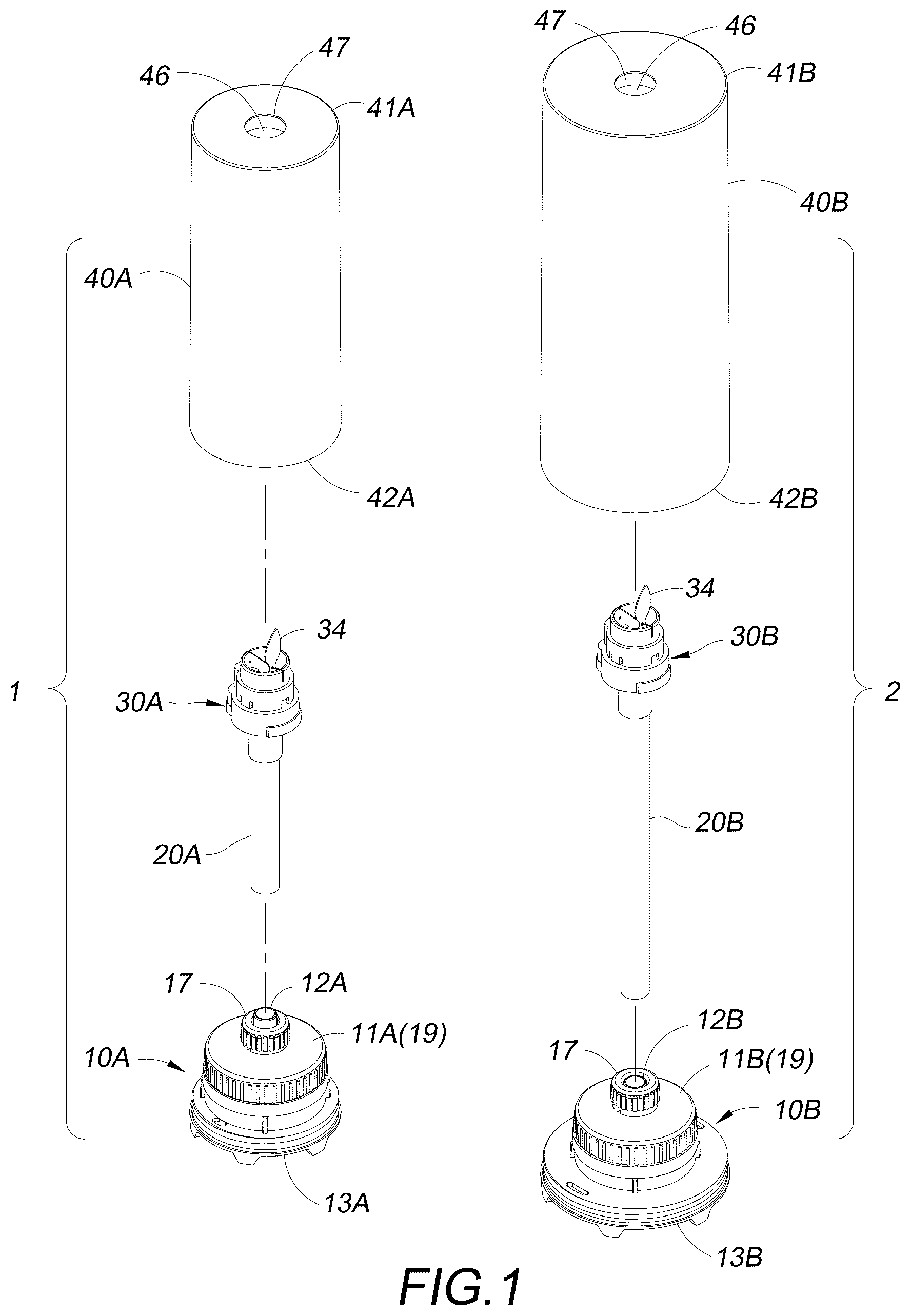
is an exploded view of a first light module and a second light module of the present invention;
is a perspective view of the first and second light modules of the present invention;
is a cross-sectional side view of the first light module of the present invention;
is a cross-sectional side view of the second light module of the present invention;
is a schematic view showing the assembly of the first and second light modules during packaging in accordance with the present invention;
is a cross-sectional side view of the first and second light modules during packaging in accordance with the present invention;
is a cross-sectional side view of a third light module in accordance with the present invention;
is a schematic view of the assembly of the first, second and third light modules during packaging in accordance with the present invention;
is a cross-sectional side view of the first, second and third light modules during packaging in accordance with the present invention; and
is a perspective view of the first, second and third light modules during packaging in accordance with the present invention.
DESCRIPTION OF THE PREFERRED EMBODIMENTS
With reference to to 4 for a candle light with a modular design that can facilitate the packaging and transportation in accordance with the present invention, the candle light includes a first light module 1 , and a second light module 2 in a shape substantially the same as the first light module 1 .
The first light module 1 includes a first base 10 A, a first support tube 20 A, a first simulated flame lighting module 30 A, and a first sleeve 40 A.
The first sleeve 40 A is in a substantially cylindrical shape, and has a first installation space 44 A defined between its top 41 A, bottom 42 A and inner periphery 43 A for installing the first base 10 A, the first support tube 20 A and the first simulated flame lighting module 30 A. The first base 10 A is assembled with the bottom 42 A, the first simulated flame lighting module 30 A is assembled with the top 41 A, and the first support tube 20 A is assembled between the first simulated flame lighting module 30 A and the first base 10 A.
The first base 10 A is provided with a battery 50 A, the battery 50 A is electrically connected to the first simulated flame lighting module 30 A for supplying electric power for the operation of the first light module 1 .
The second light module 2 includes a second base 10 B, a second support tube 20 B, a second simulated flame lighting module 30 B, and a second sleeve 40 B.
The second sleeve 40 B is in a substantially cylindrical shape, and has a second installation space 44 B defined between its top 41 B, bottom 42 B and inner periphery 43 B.
The inner periphery 43 B is greater than the outer periphery 45 A of the first sleeve 40 A, and the second installation space 44 B is provided for installing the second base 10 B, the second support tube 20 B, and the second simulated flame lighting module 30 B. The second base 10 B is detachably assembled with the bottom 42 B, the second simulated flame lighting module 30 B is detachably assembled with the top 41 B, and the second support tube 20 B is detachably assembled between the second simulated flame lighting module 30 B and the second base 10 B.
The second base 10 B is provided with a battery 50 B, the battery 50 B is electrically connected to the second simulated flame lighting module 30 B for supplying electric power for the operation of the second light module 2 .
The present invention is characterized in that the top 11 A of the first base 10 A is provided with a protruding first connecting tube 12 A for assembling and positioning the first support tube 20 A, and the bottom 13 A of the first base 10 A is concave upward and provided with a first upper concave space 14 A.
The top 11 B of the second base 10 B is provided with a protruding second connecting tube 12 B for detachably assembling and positioning the second support tube 20 B.
In , since the inner periphery 43 B of the second sleeve 40 B is greater than the outer periphery 45 A of the first sleeve 40 A, after the second simulated flame lighting module 30 B, the second support tube 20 B and the second base 10 B is disassembled from the second sleeve 40 B, the whole first light module 1 can be stored in the second installation space 44 B, and then the second base 10 B is assembled with the bottom 42 B of the second sleeve 40 B, so that the second connecting tube 12 B can be embedded in the first upper concave space 14 A of the first base 10 A.
After the second base 10 B is assembled with the bottom 42 B of the second sleeve 40 B, the first light module 1 is concealed between the second sleeve 40 B and the second base 10 B, and the second simulated flame lighting module 30 B and the second support tube 20 B are stored outside the second sleeve 40 B, so that the light modules of different sizes that originally needed to be packaged separately can be packaged together to reduce volume and transportation costs.
The modular design of the candle light is not limited to integrating and packaging two light modules together. In to 9 , the candle light further includes a third light module 3 in a shape substantially the same as the first light module 1 .
The third light module 3 includes a third base 10 C, a third support tube 20 C, a third simulated flame lighting module 30 C, and a third sleeve 40 C.
The third sleeve 40 C is in a substantially cylindrical shape and has a third installation space 44 C defined between its top 41 C, bottom 42 C and inner periphery 43 C, and the inner periphery 43 C is greater than the outer periphery 45 B of the second sleeve 40 B. The third installation space 44 C is provided for installing the third base 10 C, the third support tube 20 C and the third simulated flame lighting module 30 C. The third base 10 C is detachably assembled with the bottom 42 C, the third simulated flame lighting module 30 C is detachably assembled with the top 41 C, and the third support tube 20 C is detachably assembled between the third simulated flame lighting module 30 C and the third base 10 C.
The third base 10 C is provided with a battery 50 C, the battery 50 C is electrically connected to the third simulated flame lighting module 30 C for supplying electric power for the operation of the third light module 3 .
In the figures, the top 11 C of the third base 10 C is provided with a protruding third connecting tube 12 C for detachably assembling the third support tube 20 C; and the bottom 13 B of the second base 10 B is concave up with a second upper concave space 14 B.
After the third simulated flame lighting module 30 C, the third support tube 20 C and the third base 10 C are disassembled from the third sleeve 40 C, the second sleeve 40 B and the second base 10 B of the second light module 2 can be stored in the third installation space 44 C, and then the third base 10 C is assembled with the bottom 42 C of the third sleeve 40 C, so that the third connecting tube 12 C can be embedded in the second upper concave space 14 B of the second base 10 B.
After the third base 10 C is assembled with the bottom 42 C of the third sleeve 40 C, the second sleeve 40 B and the second base 10 B can be concealed between the third sleeve 40 C and the third base 10 C, and the third simulated flame lighting module 30 C, the third support tube 20 C, the second simulated flame lighting module 30 B and the second support tube 20 B are stored outside the third sleeve 40 C. As shown in , a packaging box 60 is provided for packaging to allow candle lights of different sizes to be packaged together, thereby reducing the volume and transportation cost of separate packaging of each light module.
Through the above structure, the present invention integrates the base, the simulated flame lighting module and the sleeve of the candle light through modular design, so that at least two candle lights of different sizes can be packaged together, not only providing consumers with various sizes to choose from, but also reducing volume and packaging and transportation costs.
The implementation of each light module is further described as follows:
With reference to for the first light module 1 taken as an example, the top 41 A of the first sleeve 40 A is provided with a through hole 46 connected to the first installation space 44 A, and the through hole 46 is used for positioning the first simulated flame lighting module 30 A.
The first simulated flame lighting module 30 A includes a base plate 31 assembled with the first support tube 20 A, an outer frame component 32 assembled with the top of the base plate 31 and located under the through hole 46 , and a printed circuit board assembly (PCBA) 33 fixed between the base plate 31 and the outer frame component 32 , and a swinging part 34 swingably installed on the outer frame component 32 . The base plate 31 is provided with a perforation 311 for electrically connecting a power cord 35 between the battery 50 A and the printed circuit board assembly 33 .
The swinging part 34 includes a simulated flame sheet 341 protruding from the corresponding through hole 46 , and a pendulum 342 located under the simulated flame sheet 341 .
The printed circuit board assembly 33 includes a substrate 331 fixed to the base plate 31 , a drive element 332 arranged on the substrate 331 , and an LED 333 projecting light towards the simulated flame sheet 341 . The drive element 332 is located under the pendulum 342 , and the drive element 332 can directly or indirectly drive the pendulum 342 of the swinging part 34 to swing and move. For example, driving means including as a motor and a transmission gear, or a motor and a transmission rod, or a magnetic drive can be used to produce the simulation of the flickering light of flames of the simulated flame sheet 341 .
Similarly, in , 4 and 7 , the second and third sleeves 40 B, 40 C and the second and third simulated flame lighting modules 30 B, 30 C have the same structure of the first sleeve 40 A and the first simulated flame lighting module 30 A. For example, the sleeve is provided with a through hole 46 , and the simulated flame lighting module includes a base plate 31 , an outer frame component 32 , a printed circuit board assembly 33 , a swinging part 34 , a power cord 35 , etc., and their structure and assembly will not be described here in detail.
In , in order to facilitate the removal of each base from the corresponding sleeve, the first upper concave space 14 A of the first base 10 A and the second upper concave space 14 B of the second base 10 B are provided with two force applying plates 15 separated from each other respectively, so that users may apply force through the two force applying plates 15 to remove the first base 10 A and the second base 10 B from the corresponding sleeve.
A positioning spacing 16 is defined between every two force applying plates 15 . When the first light module 1 is stored in the second installation space 44 B, and the second base 10 B is assembled with the bottom 42 B of the second sleeve 40 B, the second connecting tube 12 B is embedded in the positioning spacing 16 at the bottom 13 A of the first base 10 A.
When the second sleeve 40 B and the second base 10 B are stored in the third installation space 44 C, and the third base 10 C is assembled with the bottom 42 C of the third sleeve 40 C, the third connecting tube 12 C is embedded in positioning spacing 16 at the bottom 13 B of the second base 10 B. Similarly, the bottom 13 C of the third base 10 C is also provided with a force applying plate 15 to facilitate users to remove the third base 10 C.
In , the center of the first base 10 A is provided with a concave compartment 18 for installing a battery 50 A, a cover 19 is clamped around the compartment 18 from top to bottom or screwed tightly with the compartment, and the first connecting tube 12 A is arranged on the cover 19 .
The first connecting tube 12 A is provided with an outer thread, the outer thread is provided and screwed with a packing nut 17 , such that after the first support tube 20 A is assembled with the first connecting tube 12 A, the first support tube 20 A is packed and positioned through the packing nut 17 .
The power cord 35 can extend from the first connecting tube 12 A, and further extend inwardly upward in the first support tube 20 A to electrically connect the printed circuit board assembly 33 , and the power cord 35 is provided with an electrical connector 36 for quickly and electrically connect the printed circuit board assembly 33 and the battery 50 A.
Similarly, in , 4 , and 7 , the second, third base 10 B, 10 C has the same assembly and structure of the first base 10 A. For example, the base includes a compartment 18 , a cover 19 , a packing nut 17 , and a power cord 35 , and the assembly of the electrical connector 36 , etc. which will not be described in details here.
In , 4 , and 7 , the through holes 46 of the first, second, and third sleeves 40 A, 40 B, and 40 C are provided with a circular wall 47 extending toward the corresponding first, second, and third installation spaces 44 A, 44 B, and 44 C, respectively.
In , when the first, second, and third sleeves 40 A, 40 B, 40 C are stacked on each other, the circular wall 47 of the third sleeve 40 C is stacked on the top 41 B of the second sleeve 40 B, the circular wall 47 of the second sleeve 40 B is stacked on the top 41 A of the first sleeve 40 A, and three through holes 46 are aligned and communicated with the first installation space 44 A; the total length of the three circular walls 47 is greater than or equal to the height of the simulated flame sheet 341 of the first simulated flame lighting module 30 A to protect the simulated flame sheet 341 from being bent or damaged.
The above embodiments and drawings are only examples of preferred embodiments of the present invention, which are not intended to limit the scope of the present invention, numerous modifications and variations could be made thereto by those skilled in the art without departing from the scope and spirit of the invention as set forth in the claims, and any similarities with the purpose, structure, device, feature, etc. of the present invention shall fall within the patent scope of the present invention.
Figures (10)
Citations
This patent cites (4)
- US5921767
- US2018/0003352
- US2020/0217469
- US2025/0093003