Side Airbag Device and Airbag Folding Method
Abstract
The side airbag device includes an airbag in a folded state, including a pair of sheets provided facing each other, and an inflator including a supply port for supplying gas and configured to supply gas into the airbag. The airbag, with the pair of sheets deployed, includes a first portion including one end of the sheets in a first direction, a second portion including the other end, a third portion positioned between the first portion and the second portion, and a fourth portion positioned between the first portion and the third portion. The airbag is folded into a first state with the first portion and the fourth portion positioned between a pair of sheet parts corresponding to a part of the pair of sheets and included in the third portion, and further folded into a second state with a part of the pair of sheet parts arranged to sandwich the first portion and the fourth portion, folded with an accordion fold in a second direction perpendicular to the first direction. The supply port is arranged between another part of the pair of sheet parts.
Claims (7)
1. A side airbag device comprising: an airbag including a pair of sheets provided facing each other and connected to each other, the airbag folded; and an inflator including a supply port for supplying gas, the inflator configured to supply gas into the airbag, wherein when the airbag is viewed along a thickness direction of the pair of sheets, with the pair of sheets deployed in a flat shape, the airbag includes: a first portion including one end of the sheets in a first direction; a second portion including the other end of the sheets in the first direction; a third portion positioned between the first portion and the second portion in the first direction; and a fourth portion positioned between the first portion and the third portion in the first direction, wherein the airbag is folded into the following states: (i) a state with at least a part of the first portion and the fourth portion positioned between a pair of sheet parts corresponding to a part of the pair of sheets, the pair of sheet parts included in the third portion, and (ii) a state with a part of the pair of sheet parts arranged to sandwich the at least part of the first portion and the fourth portion, folded with an accordion fold in a second direction perpendicular to the first direction, together with the at least part of the first portion and the fourth portion, and the supply port is arranged between another part of the pair of sheet parts.
6. A method of folding an airbag included in a side airbag device, the airbag including a pair of sheets provided facing each other and connected to each other, wherein when the airbag is viewed along a thickness direction of the pair of sheets, with the pair of sheets deployed in a flat shape, the airbag includes: a first portion including one end of the sheets in a first direction; a second portion including the other end of the sheets in the first direction; a third portion positioned between the first portion and the second portion in the first direction; and a fourth portion positioned between the first portion and the third portion in the first direction, wherein the method comprising: (i) folding the airbag so that at least a part of the first portion and the fourth portion are positioned between a pair of sheet parts corresponding to a part of the pair of sheets, the pair of sheet parts included in the third portion; and (ii) folding, with an accordion fold, a part of the pair of sheet parts arranged to sandwich the at least part of the first portion and the fourth portion, together with the at least part of the first portion and the fourth portion in a second direction perpendicular to the first direction.
Show 5 dependent claims
2. The side airbag device according to claim 1 , wherein the pair of sheet parts includes a yet another part, when the pair of sheet parts deployed in a flat shape is viewed along the thickness direction, the another part, the part, and the yet another part are arranged sequentially in the second direction, and the airbag is folded, with the yet another part in a rolled-up state.
3. The side airbag device according to claim 1 , wherein in the airbag, a part including an edge part included in an end of the first portion in the second direction is folded toward a direction opposite to the second direction.
4. The side airbag device according to claim 1 , wherein the airbag includes a tag attached to the first portion so as to protrude in the first direction, and the airbag is folded so that the one end of the sheets in the first direction is positioned between the pair of sheet parts included in the third portion, and further so that at least a part of the tag is positioned outside the pair of sheet parts.
5. The side airbag device according to claim 1 , wherein when the airbag with the pair of sheets deployed in a flat shape is viewed along the thickness direction, a dimension of the airbag in the first direction is longer than a dimension of the airbag in the second direction.
7. The method of folding the airbag according to claim 6 , wherein the airbag includes a tag attached to the first portion so as to protrude in the first direction, the step (i) includes the steps of: folding the airbag so that the one end of the sheets in the first direction is positioned between the pair of sheet parts included in the third portion, and further so that at least a part of the tag is positioned outside the pair of sheet parts; and adjusting a position of the first portion positioned between the pair of sheet parts, based on a position and a length of the at least part of the tag positioned outside the pair of sheet parts.
Full Description
Show full text →
CROSS REFERENCE TO RELATED APPLICATIONS
The present application claims the priority based on Japanese Patent Application No. 2023-221088 filed on Dec. 27, 2023, the disclosure of which is hereby incorporated by reference in its entirety.
BACKGROUND
Field
The present disclosure relates to a side airbag device and an airbag folding method.
Related Art
A side airbag device installed in a seat of a vehicle has been known in the prior art. When the vehicle is subjected to an impact, the side airbag device deploys an airbag between an occupant seated in the seat and the closest side wall of the vehicle to the seat. With respect to the side airbag according to Japanese Patent Laid-Open Publication No. H11-59311, in the process of folding its airbag in the manufacturing stage of its side airbag device, the airbag is first folded with an accordion fold in the direction corresponding to the front-back direction of the vehicle. Thereafter, the upper end part of the airbag folded with the accordion fold is folded forward, and further folded downward. The lower end part of the airbag folded with the accordion fold is folded forward, and further folded upward. In the process of deployment of the airbag, first, the folded upper end part and the folded lower end part deploy upward and downward, respectively. Thereafter, the airbag folded with the accordion fold deploys toward the front of the vehicle. This allows the airbag to quickly cover the side part of the occupant in a vertical wide area. As a result, the occupant is surely restricted.
In the airbag according to Japanese Patent Laid-Open Publication No. H11-59311, first, the upper end part and the lower end part of the airbag deploy, and thereafter the airbag deploys forward. This causes a delay in the timing of the airbag deploying forward. The following problem also arises because the airbag deploys forward after having deployed in the up-down direction. Therefore, the upper arm of an occupant is pushed against the side part of the chest of the occupant via the airbag deployed in the up-down direction, due to the door or the wall deformed to the inside of the vehicle subjected to an external impact. As a result, the chest of the occupant is compressed by the upper arm of the occupant.
SUMMARY
The present disclosure may be embodied in the following aspects.
In one aspect of the present disclosure, a side airbag device is provided. The side airbag device includes an airbag in a folded state, including a pair of sheets provided facing each other and connected to each other, and an inflator including a supply port for supplying gas and configured to supply gas into the airbag. When the airbag is viewed along a thickness direction of the pair of sheets, with the pair of sheets deployed in a flat shape, the airbag includes a first portion including one end of the sheets in a first direction, a second portion including the other end of the sheets in the first direction, a third portion positioned between the first portion and the second portion in the first direction, and a fourth portion positioned between the first portion and the third portion in the first direction. The airbag is folded into the following states: (i) a state with at least a part of the first portion and the fourth portion positioned between a pair of sheet parts corresponding to a part of the pair of sheets and included in the third portion, and (ii) a state with a part of the pair of sheet parts arranged to sandwich the at least part of the first portion and the fourth portion, folded with an accordion fold in a second direction perpendicular to the first direction, together with the at least part of the first portion and the fourth portion. The supply port is arranged between another part of the pair of sheet parts.
BRIEF DESCRIPTION OF THE DRAWINGS
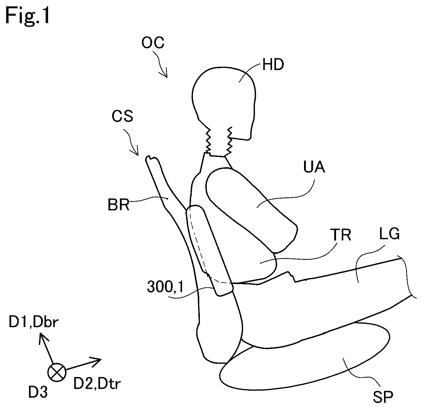
is an explanatory diagram illustrating the arrangement of a side airbag device 1 as an embodiment of the present disclosure.
is an explanatory diagram illustrating an airbag 100 when it is deployed.
is a flowchart describing the method of folding the airbag 100 .
shows the airbag 100 when viewed along a thickness direction D 3 of a pair of a sheet St 100 and a sheet St 200 .
is an explanatory diagram illustrating the airbag 100 when the processes in step S 320 have been completed.
is another explanatory diagram illustrating the airbag 100 when the processes in step S 320 have been completed.
is a schematic diagram corresponding to a cross-sectional view taken along a line VII-VII of .
is a schematic diagram corresponding to a cross-sectional view taken along a line VIII-VIII of .
is another schematic diagram corresponding to a cross-sectional view taken along the line VIII-VIII of .
is an explanatory diagram illustrating the process of step S 340 in .
is an explanatory diagram illustrating the airbag 100 when the process of step S 340 has been completed.
is an explanatory diagram schematically illustrating the process of step S 360 .
is an explanatory diagram illustrating the airbag 100 when the process of step S 360 has been completed.
is an explanatory diagram illustrating the side airbag device 1 before the airbag 100 deploys.
is an explanatory diagram illustrating the side airbag device 1 when the airbag 100 starts deploying in a second direction D 2 .
is an explanatory diagram illustrating the side airbag device 1 when the airbag 100 starts deploying also in a first direction D 1 in addition to the second direction D 2 .
is an explanatory diagram illustrating the side airbag device 1 when the airbag 100 is still deploying in the first direction D 1 while it has nearly fully deployed in the second direction D 2 .
is an explanatory diagram illustrating the side airbag device 1 when the airbag 100 is deployed.
is an explanatory diagram illustrating the airbag 100 in the process of deployment.
DETAILED DESCRIPTION
A. Embodiment
A1. Configuration of Side Airbag Device
is an explanatory diagram illustrating the arrangement of the side airbag device 1 as an embodiment of the present disclosure. The side airbag device 1 is installed in a seat CS of a vehicle (refer to the center part of the middle range in ). The side airbag device 1 is configured to deploy the airbag 100 , when the vehicle is subjected to an external impact, between an occupant OC seated in the seat CS of the vehicle and the closest side wall of the vehicle to the seat CS. The side airbag device 1 , in its unused state, has an elongated outer shape. The side airbag device 1 is installed in the side part of the seat CS of the vehicle so that an extending direction Dbr of a backrest BR of the seat CS of the vehicle from a seat base SP coincides with the longitudinal direction D 1 of the side airbag device 1 .
The direction, which is perpendicular to the direction Dbr and where a torso TR of the occupant OC seated in the seat CS is positioned with respect to the backrest BR, is defined as a direction Dtr. For the sake of ease of technical understanding, shows, as the occupant OC, a dummy of the occupant OC having a head HD, the torso TR, an upper arm UA, and a leg LG. shows only the outer shape of the skeletal part of the backrest BR of the seat CS, without its cushion part.
is an explanatory diagram illustrating the airbag 100 when it is deployed by the side airbag device 1 . The side airbag device 1 includes the airbag 100 , an inflator 200 , and a housing bag 300 . In , the airbag 100 and the inflator 200 are housed in the housing bag 300 . For the sake of ease of technical understanding, shows neither the inflator 200 nor the housing bag 300 .
The airbag 100 inflates and deploys when inflation gas is supplied from the inflator 200 (refer to ). The airbag 100 includes the pair of sheets St 100 , St 200 , which are provided facing each other and connected to each other. shows the pair of sheets St 100 , St 200 in a folded state.
The inflator 200 supplies gas into the airbag 100 . When gas is supplied by the inflator 200 , the airbag 100 then inflates in the direction Dtr where the torso TR is positioned with respect to the backrest BR and in the extending direction Dbr of the backrest BR (refer to ). The inflator 200 has a cylindrical shape. The inflator 200 includes a supply port 220 for supplying gas through it. The supply port 220 is provided on one end face of the cylindrical inflator 200 . A part of the inflator 200 including the one end on which the supply port 220 is provided is placed inside the airbag 100 . The longitudinal direction of the cylindrical inflator 200 coincides with the longitudinal direction D 1 of the side airbag device 1 before deployment. In the present specification, this direction is defined as the first direction D 1 . The side airbag device 1 is installed in the seat CS of the vehicle so that the supply port 220 of the inflator 200 is positioned lower than the expected position of the shoulder joint of the occupant OC (refer to ).
The housing bag 300 houses the folded airbag 100 , and the inflator 200 partially placed inside the airbag 100 (refer to the center part of the middle range in ). The housing bag 300 reduces the possibility of foreign matter entering the inside of the side airbag device 1 . When the airbag 100 deploys, the housing 300 tears. For the sake of ease of technical understanding, shows neither the torn housing bag 300 nor the inflator 200 .
is a flowchart describing the method of folding the airbag 100 included in the side airbag device 1 . In step S 100 , the airbag 100 , the inflator 200 , and the housing bag 300 are prepared.
In step S 200 , the inflator 200 is attached to the airbag 100 . More specifically, the inflator 200 is inserted into the airbag 100 through an insertion port 110 provided on the airbag 100 . Thereafter, the inflator 200 and the airbag 100 are fixed to each other. The inflator 200 is partially exposed to the outside through the insertion port 110 provided on the airbag 100 .
In step S 300 , the airbag 100 is folded.
shows the airbag 100 when viewed along the thickness direction D 3 of the pair of sheets St 100 , St 200 included in the airbag 100 in the state where the pair of sheets St 100 , St 200 is deployed in a flat shape. to are explanatory diagrams for explaining the method of folding the airbag 100 , while not showing the precise shape of the airbag 100 .
The sheets St 100 , St 200 have substantially the same shape. The sheets St 100 , St 200 are arranged to overlap, and their outer peripheries are sewn together. In , the sewn parts of the sheets St 100 , St 200 are illustrated with a two-dot line. In , the sheet St 100 is illustrated in a front side. In , the sheet St 200 is positioned behind the sheet St 100 .
The direction, which is perpendicular to the longitudinal direction of the inflator 200 attached to the airbag 100 , is defined as the second direction D 2 (refer to the right-side part of the lower range in ). The second direction D 2 and the first direction D 1 are perpendicular to each other. The second direction D 2 and the first direction D 1 are perpendicular to the third direction D 3 which is the thickness direction D 3 of the sheets St 100 , St 200 . The first direction D 1 , the second direction D 2 , and the third direction D 3 form a left-handed coordinate system.
The airbag 100 has a dimension Dm 1 in the first direction D 1 and a dimension Dm 2 in the second direction D 2 , where the dimension Dm 1 is longer than the dimension Dm 2 . The airbag 100 includes a first portion P 10 , a second portion P 20 , a third portion P 30 , a fourth portion P 40 , and a fifth portion P 50 .
The first portion P 10 is the portion including one end T 11 of the sheets St 100 , St 200 in the first direction D 1 (refer to the upper range in ). The first portion P 10 includes a tag TG 10 attached to it. The tag TG 10 is a rectangular sheet. The tag TG 10 has one end sewn to the first portion P 10 . The tag TG 10 has a dimension in the first direction D 1 shorter than the dimension Dm 1 of the airbag 100 . The tag TG 10 has a dimension in the second direction D 2 shorter than the dimension Dm 2 of the airbag 100 . The tag TG 10 protrudes from the first portion P 10 in the first direction D 1 .
The second portion P 20 is the portion including the other end T 12 of the sheets St 100 , St 200 in the first direction D 1 (refer to the lower range in ). The second portion P 20 includes a tag TG 20 attached to it. The tag TG 20 has the same configuration as the configuration of the tag TG 10 . The tag TG 20 protrudes from the second portion P 20 in the direction opposite to the first direction D 1 .
The third portion P 30 is a portion positioned between the first portion P 10 and the second portion P 20 in the first direction D 1 (refer to the right-side part of the middle range in ). The pair of sheet parts, which is a part of the pair of sheets St 100 , St 200 and is included in the third portion P 30 , is defined as sheet parts St 130 and St 230 .
The fourth portion P 40 is the portion positioned between the first portion P 10 and the third portion P 30 in the first direction D 1 (refer to the right-side part of the upper range in ). The fourth portion P 40 , when the airbag 100 deploys and inflates, is positioned to surround the first portion P 10 when viewed along the direction opposite to the first direction D 1 .
The fifth portion P 50 is the portion positioned between the second portion P 20 and the third portion P 30 in the first direction D 1 (refer to the right-side part of the lower range in ). The fifth portion P 50 , when the airbag 100 deploys and inflates, is positioned to surround the second portion P 20 when viewed along the first direction D 1 .
The second portion P 20 , the fifth portion P 50 , the third portion P 30 , the fourth portion P 40 , and the first portion P 10 are arranged in this order in the first direction D 1 .
Step S 300 in includes steps S 320 , S 340 , S 360 , and S 380 .
In step S 320 , the airbag 100 is folded so that the first portion P 10 and the fourth portion P 40 are positioned between the pair of sheet parts St 130 , St 230 included in the third portion P 30 . Similarly, the airbag 100 is folded so that the second portion P 20 and the fifth portion P 50 are positioned between the pair of sheet parts St 130 , St 230 included in the third portion P 30 . The method of folding the first portion P 10 and the fourth portion P 40 and the method of folding the second portion P 20 and the fifth portion P 50 are called “inward fold” or “tuck-in fold”.
Step S 320 in includes steps S 322 , S 324 , S 326 , and S 328 .
In step S 322 , the airbag 100 is folded so that the one end T 11 of the sheets St 100 , St 200 in the first direction D 1 is positioned between the pair of sheet parts St 130 , St 230 included in the third portion P 30 , and further so that at least a part of the tag TG 10 is positioned outside the pair of sheet parts St 130 , St 230 arranged to overlap. In this case of folding the airbag 100 , the fourth portion P 40 is also positioned between the pair of sheet parts St 130 , St 230 included in the third portion P 30 .
In step S 324 , the position of the first portion P 10 positioned between the pair of sheet parts St 130 , St 230 arranged to overlap is adjusted, based on the position and the length of the portion of the tag TG 10 positioned outside the pair of sheet parts St 130 , St 230 . More specifically, an operator adjusts the position of the first portion P 10 by holding the tag TG 10 to move the tag TG 10 . Moreover, an operator adjusts the position of the first portion P 10 by adjusting the portion subjected to a valley fold of the first portion P 10 or the fourth portion P 40 .
In step S 322 , the airbag 100 is folded so that at least a part of the tag TG 10 is positioned outside the pair of sheet parts St 130 , St 230 arranged to overlap. This allows, in step S 324 , control of the position and the length of at least a part of the tag TG 10 positioned outside the pair of sheet parts St 130 , St 230 included in the third portion P 30 , thereby controlling the position of the first portion P 10 folded between the pair of sheet parts St 130 , St 230 .
In step S 326 , the airbag 100 is folded so that the other end T 12 of the sheets St 100 , St 200 in the first direction D 1 is positioned between the pair of sheet parts St 130 , St 230 included in the third portion P 30 , and further so that at least a part of the tag TG 20 is positioned outside the pair of sheet parts St 130 , St 230 arranged to overlap. In this case of folding the airbag 100 , the fifth portion P 50 is also positioned between the pair of sheet parts St 130 , St 230 included in the third portion P 30 .
In step S 328 , the position of the second portion P 20 positioned between the pair of sheet parts St 130 , St 230 arranged to overlap is adjusted, based on the position and the length of the portion of the tag TG 20 positioned outside the pair of sheet parts St 130 , St 230 . The specific method of adjusting the position of the second portion P 20 is the same as the method of adjusting the position of the first portion P 10 in step S 324 .
The processes in steps S 326 and S 328 are executed to allow control of the position of the second portion P 20 folded between the pair of sheet parts St 130 , St 230 . The processes in step S 320 including steps S 322 to S 328 are executed, thereby allowing proper folding of the airbag 100 .
is an explanatory diagram illustrating the airbag 100 when the processes in step S 320 have been completed. shows the image of the first portion P 10 and the fourth portion P 40 in a folded state and the image of the second portion P 20 and the fifth portion P 50 in a folded state, both with dashed lines.
is another explanatory diagram illustrating the airbag 100 when the processes in step S 320 have been completed. shows the position of the one end T 11 and the position of the other end T 12 of the sheets St 100 , St 200 in the first direction D 1 , both with dashed lines. In and , the tag TG 10 and the tag TG 20 are partially positioned outside the pair of sheet parts St 130 , St 230 .
is a schematic diagram corresponding to a cross-sectional view taken along the line VII-VII of . In , the airbag 100 is folded in the following state. The first portion P 10 and the fourth portion P 40 are positioned between the pair of sheet parts St 130 , St 230 included in the third portion P 30 (refer to the center part of the upper range in ). The one end T 11 of the sheets St 100 , St 200 in the first direction D 1 is positioned between the pair of sheet parts St 130 , St 230 included in the third portion P 30 . At least a part of the tag TG 10 is positioned outside the pair of sheet parts St 130 , St 230 . The second portion P 20 and the fifth portion P 50 are positioned between the pair of sheet parts St 130 , St 230 included in the third portion P 30 (refer to the center part of the lower range in ). The other end T 12 of the sheets St 100 , St 200 in the first direction D 1 is positioned between the pair of sheet parts St 130 , St 230 included in the third portion P 30 . At least a part of the tag TG 20 is positioned outside the pair of sheet parts St 130 , St 230 .
is a schematic diagram corresponding to a cross-sectional view taken along the line VIII-VIII of . The first portion P 10 includes a part P 21 including the edge part included in the end of the first portion P 10 in the second direction D 2 . In step S 326 , the part P 21 is folded toward the direction opposite to the second direction D 2 (also refer to the part with the dashed lines of the first portion P 10 in ). The first portion P 10 includes a part P 22 including the edge part included in the end of the first portion P 10 in the direction opposite to the second direction D 2 . The part P 22 is folded toward the second direction D 2 . As a result, the first portion P 10 is folded into a trapezoidal shape.
In the present aspect, the first portion P 10 is folded into a small size and arranged between the pair of sheet parts St 130 , St 230 included in the third portion P 30 . The present aspect provides the following effect, compared to an aspect in which the part including the edge part included in the end of the first portion P 10 in the first direction D 1 is folded in the direction opposite to the first direction D 1 . The present aspect allows the gas, which is filled between the pair of sheet parts St 130 , St 230 included in the third portion P 30 , to smoothly flow toward the tip of the first portion P 10 in the first direction D 1 , that is, toward the one end T 11 of the airbag 100 in the first direction D 1 (refer to the part with the dashed lines of the first portion P 10 in ). This allows more reliable and rapid deployment of the first portion P 10 and the fourth portion P 40 in the first direction D 1 .
is a schematic diagram of another aspect corresponding to a cross-sectional view taken along the line VIII-VIII of . In , the parts P 21 , P 22 of the first portion P 10 are folded to the side opposite to the side shown in . The first portion P 10 may be folded as shown in , unlike the aspect in .
In step S 326 , the second portion P 20 is also folded in the same aspect as the first portion P 10 shown and . As a result, the second portion P 20 is folded into a trapezoidal shape. The present configuration allows more reliable and rapid deployment of the second portion P 20 and the fifth portion P 50 in the direction opposite to the first direction D 1 .
The pair of sheet parts St 130 , St 230 each has a part St 131 and a part St 231 , respectively, which are arranged to sandwich the first portion P 10 , the fourth portion P 40 , the second portion P 20 , and the fifth portion P 50 . In step S 340 , the parts St 131 , St 231 , together with the first portion P 10 , the fourth portion P 40 , the second portion P 20 , and the fifth portion P 50 , are folded with a so-called accordion fold in a zigzag pattern in the second direction D 2 perpendicular to the first direction D 1 . The meaning of being folded with an accordion fold in the second direction D 2 is that a target is folded with an accordion fold so that the dimension of the target in the second direction D 2 becomes smaller.
is an explanatory diagram illustrating the process of step S 340 in . In step S 340 , the part St 131 of the sheet part St 130 is folded three times with mountain folds along the first direction D 1 . The sheet part St 130 is folded twice with valley folds along the first direction D 1 . There are valley creases Fv and mountain folds Fm, where each of the valley creases Fv is positioned between mountain folds Fm. The part St 231 of the sheet part St 230 is also folded together with the sheet part St 131 of the sheet part St 130 . The first portion P 10 , the fourth portion P 40 , the second portion P 20 , and the fifth portion P 50 positioned between the sheet parts St 131 , St 231 of the sheet parts St 130 , St 230 are also folded together with the sheet part St 131 of the sheet part St 130 .
is an explanatory diagram illustrating the airbag 100 when the process of step S 340 has been completed. In the state shown in , the airbag 100 is folded as follows. The first portion P 10 , the fourth portion P 40 , the second portion P 20 , and the fifth portion P 50 in a folded state are positioned between the pair of sheet parts St 130 , St 230 included in the third portion P 30 . Moreover, in this state, the parts St 131 , St 231 of the pair of sheet parts St 130 , St 230 arranged to sandwich the first portion P 10 , the fourth portion P 40 , the second portion P 20 , and the fifth portion P 50 are folded with an accordion fold, together with the first portion P 10 , the fourth portion P 40 , the second portion P 20 , and the fifth portion P 50 , in the second direction D 2 perpendicular to the first direction D 1 .
In this state, the supply port 220 of the inflator 200 is arranged between another part St 132 and another part St 232 of the pair of sheet parts St 130 , St 230 (refer to the left-side part in ). The another parts St 132 , St 232 of the pair of sheet parts St 130 , St 230 are not folded with an accordion fold.
The pair of sheet parts St 130 , St 230 each has a yet another part St 133 and a yet another part St 233 , respectively, in addition to the parts St 131 , St 231 folded with an accordion fold, and the another parts St 132 , St 232 arranged with the supply port 220 of the inflator 200 (refer to the right-side part of the upper range in , and the right-side part of the upper range in ). The pair of sheet parts St 130 , St 230 each has the another parts St 132 , St 232 , the parts St 131 , St 231 , and the yet another parts St 133 , St 233 , respectively, which are arranged sequentially in the second direction D 2 . The yet another parts St 133 , St 233 of the pair of sheet parts St 130 , St 230 are not folded with an accordion fold.
is an explanatory diagram schematically illustrating the process of step S 360 . schematically shows the process of step S 360 of the airbag 100 in when viewed along the first direction D 1 . In step S 360 , the yet another parts St 133 , St 233 of the pair of sheet parts St 130 , St 230 arranged to sandwich the first portion P 10 , the fourth portion P 40 , the second portion P 20 , and the fifth portion P 50 are rolled up, together with the first portion P 10 , the fourth portion P 40 , the second portion P 20 , and the fifth portion P 50 , in the second direction D 2 . The meaning of being rolled up in the second direction D 2 is that a target is rolled up so that the dimension of the target in the second direction D 2 becomes smaller.
Specifically, when viewed along the first direction D 1 , the yet another parts St 133 , St 233 of the pair of sheet parts St 130 , St 230 are rolled up counterclockwise with a direction in parallel to the first direction D 1 as the axis of rotation. In other words, the yet another parts St 133 , St 233 of the pair of sheet parts St 130 , St 230 are rolled up so that the sheet facing the closest wall of the vehicle to the side airbag device 1 is wound inside.
is an explanatory diagram illustrating the airbag 100 when the process of step S 360 has been completed. In step S 380 of , the folded airbag 100 is wrapped around and held by a tape FT, so that the airbag 100 is fixed in a folded state. More specifically, the folded airbag 100 is wrapped around and held by the tape FT at two portions: in the vicinity of its upper end and in the vicinity of its lower end. In , the positions of the airbag 100 held by the tape FT are illustrated with dashed lines. As a result, a part including the end of the inflator 200 where the supply port 220 is not arranged is exposed to the outside through the insertion port 110 provided on the airbag 100 .
In step S 400 of , the folded airbag 100 and the inflator 200 arranged partially in the airbag 100 are housed in the housing bag 300 . The processes of the respective steps described above are executed, and thereby the side airbag device 1 is produced (refer to the center part of the middle range in ). In the produced side airbag device 1 , the supply port 220 of the inflator 200 is arranged between the another parts St 132 , St 232 of the pair of sheet parts St 130 , St 230 (refer to ). The airbag 100 is folded in the state where the yet another parts St 133 , St 233 of the pair of sheet parts St 130 , St 230 are rolled up (refer to and ).
The present configuration has the following advantage, compared to an aspect in which all other portions of the pair of sheet parts St 130 , St 230 included in the third portion P 30 are folded with an accordion fold except for the another parts St 132 , St 232 where the supply port 220 of the inflator 200 is positioned. The present configuration allows setting of the direction of deploying the airbag 100 when gas is supplied from the inflator 200 so that the direction includes a substantial component of the third direction D 3 , and does not significantly deviate from the second direction D 2 (refer to the right-side part of the lower range in ).
The present configuration further has the following advantage, compared to an aspect in which all other portions of the pair of sheet parts St 130 , St 230 are rolled up except for the another parts St 132 , St 232 where the supply port 220 of the inflator 200 is positioned. In the aspect in which all other portions are rolled up except for the another parts St 132 , St 232 where the supply port 220 of the inflator 200 is positioned, the rolled up portions of the airbag 100 during deploying inflate largely outward while loosening, and thereafter deploy in the second direction D 2 . Therefore, there is a risk that the airbag 100 during deploying may come into contact with other peripheral components, causing a delay in deployment.
In the present embodiment, however, since the parts St 131 , St 231 of the pair of sheet parts St 130 , St 230 are folded with an accordion fold, the airbag 100 during deploying passes through a smaller space. This reduces the risk that the airbag 100 during deploying may come into contact with other peripheral components, causing a delay in deployment.
A2. Deployment of Airbag
to are explanatory diagrams respectively illustrating the airbag 100 of the side airbag device 1 in the course of deployment. As gas is being supplied from the inflator 200 , the airbag 100 transitions step by step from the state shown in to the state shown in . For the sake of ease of technical understanding, in the airbag 100 shown in to , gas is not actually supplied from the inflator 200 . For the sake of ease of technical understanding, the airbag 100 not equipped with the housing bag 300 is illustrated.
The side airbag device shown in to is arranged in the vehicle, on the side opposite to the side where the side airbag device 1 shown in to is arranged. Specifically, the side airbag device shown in to is arranged in the left seat CS on its left side, in the vehicle. The side airbag device 1 shown in to is arranged, on the other hand, in the right seat CS on its right side, in the vehicle. Accordingly, in the side airbag device shown in to , the direction of rolling up the yet another parts St 133 , St 233 of the pair of sheet parts St 130 , St 230 is opposite to the direction of rolling up in the side airbag device 1 shown in to . However, the same airbag deploying method is used for both the side airbag devices respectively arranged on the left side and the right side in a vehicle. Therefore, the airbag deploying method for the side airbag device 1 is described by referring to to .
is an explanatory diagram illustrating the side airbag device 1 before the airbag 100 deploys. In , the folded airbag 100 is wrapped around and held by the tape FT at two portions: in the vicinity of its upper end and in the vicinity of its lower end (refer to the portions attached with FT in ). The part including the end of the inflator 200 where the supply port 220 of the inflator 200 is not arranged is exposed to the outside through the insertion port 110 provided on the airbag 100 (refer to the left-side part of the lower range in ).
is an explanatory diagram illustrating the side airbag device 1 in which gas starts being supplied into the airbag 100 from the inflator 200 and the airbag 100 then starts deploying in the second direction D 2 . When the airbag 100 starts deploying in the second direction D 2 , two pieces of the tape FT are then cut out (refer to the upper range and lower range in ). In , the first portion P 10 , the fourth portion P 40 , the second portion P 20 , and the fifth portion P 50 are positioned between the sheet parts St 130 , St 230 . In other words, neither the first portion P 10 nor the fourth portion P 40 protrudes from the sheet parts St 130 , St 230 in the first direction D 1 . Neither the second portion P 20 nor the fifth portion P 50 protrudes from the sheet parts St 130 , St 230 in the direction opposite to the first direction D 1 .
is an explanatory diagram illustrating the side airbag device 1 in which gas is further supplied into the airbag 100 and the airbag 100 then starts deploying also in the first direction D 1 in addition to the second direction D 2 . In , both the first portion P 10 and the fourth portion P 40 partially protrude from the parts St 131 , St 231 of the sheet parts St 130 , St 230 in the first direction D 1 . Both the second portion P 20 and the fifth portion P 50 partially protrude from the parts St 131 , St 231 of the sheet parts St 130 , St 230 in the direction opposite to the first direction D 1 .
is an explanatory diagram illustrating the side airbag device 1 in which gas is further supplied into the airbag 100 and the airbag 100 is still deploying in the first direction D 1 while it has nearly fully deployed in the direction D 2 . In , both the first portion P 10 and the fourth portion P 40 protrude longer from the sheet parts St 131 , St 231 of the sheet parts St 130 , St 230 in the first direction D 1 , compared to the state shown in . Both the second portion P 20 and the fifth portion P 50 protrude longer from the sheet parts St 131 , St 231 of the sheet parts St 130 , St 230 in the direction opposite to the first direction D 1 , compared to the state shown in .
is an explanatory diagram illustrating the side airbag device 1 in which gas is further supplied into the airbag 100 and the airbag 100 has fully deployed. The sheet part St 130 includes an exhaust port 120 . With respect to the first direction D 1 , a part of the exhaust port 120 is positioned to the third portion P 30 , and another part of the exhaust port 120 is positioned to the fifth portion P 50 . With respect to the second direction D 2 , the exhaust port 120 is arranged to the yet another part St 133 or the yet another part St 233 of the pair of sheet parts St 130 , St 230 , subjected to rolling up. The airbag 100 fully inflates by the gas supplied from the inflator 200 , and thereafter gradually deflates by exhausting the gas through the exhaust port 120 .
As shown in to , the folded airbag 100 deploys as follows. The gas supplied between the pair of sheet parts St 130 , St 230 through the supply port 220 of the inflator 200 first extends the parts St 131 , St 231 folded with an accordion fold, so that the airbag 100 deploys in the second direction D 2 (refer to and ). Thereafter, the gas filled between the pair of sheet parts St 130 , St 230 included in the third portion P 30 pushes out the first portion P 10 and the fourth portion P 40 in the first direction D 1 , so that the airbag 100 deploys in the first direction D 1 . Similarly, the gas pushes out the second portion P 20 and the fifth portion P 50 in the direction opposite to the first direction D 1 , so that the airbag 100 deploys also in the direction opposite to the first direction D 1 (refer to to ). The gas further extends the rolled parts St 133 , St 233 , so that the airbag 100 deploys in the second direction D 2 (refer to to ).
The airbag 100 deploys as follows, in the case where the side airbag device 1 is arranged so that the extending direction Dbr of the backrest BR of the seat CS of the vehicle from the seat base SP coincides with the first direction D 1 and further so that the direction Dtr where the torso TR of the occupant OC is positioned with respect to the backrest BR coincides with the second direction D 2 (refer to the left-side part of the middle range in ).
is an explanatory diagram illustrating the airbag 100 in the middle of deployment. shows the airbag 100 in an intermediate state between the state shown in and the state shown in . In the process of deployment of the airbag 100 , the airbag 100 first deploys in the direction Dtr where the torso TR of the occupant OC seated in the seat CS is positioned with respect to the backrest BR of the seat CS (refer to and ). The airbag 100 thereafter deploys in the extending direction Dbr of the backrest BR of the seat CS (refer to , and ). Therefore, the side airbag device 1 in the present embodiment allows the airbag 100 to deploy at an earlier timing in the direction Dtr where the torso TR of the occupant OC is positioned, compared to an aspect in which the airbag 100 fully deploys in the extending direction Dbr of the backrest BR and thereafter deploys in the direction Dtr where the torso TR is positioned (refer to and ). The side airbag device 1 in the present embodiment is particularly suitable for a vehicle having a small space between the occupant OC seated in the seat CS and the closest side wall of the vehicle to the seat CS.
In the present embodiment, the airbag 100 , in the state where the first portion P 10 and the fourth portion P 40 are substantially positioned between the pair of sheet parts St 130 , St 230 included in the third portion P 30 , deploys in the direction Dtr where the torso TR is positioned with respect to the backrest BR (refer to ). Therefore, the airbag 100 , during deploying, is able to push up the upper arm UA of the occupant OC from the posture of hanging down along the torso TR toward the posture of extending along the second direction D 2 (refer to and ). This reduces the risk that the chest of the occupant OC may be compressed by the upper arm UA of the occupant OC via the airbag 100 after deployment due to the door or the wall deformed inward into the vehicle subjected to an external impact. This also reduces the pushing force from the outside to the chest of the occupant OC. The side airbag device 1 is configured so that the airbag 100 , during deploying, comes into contact with the portion beyond the elbow and pushes up the upper arm UA, and is installed in the seat CS of the vehicle (refer to ).
In the present embodiment, the first portion P 10 and the fourth portion P 40 , and the second portion P 20 and the fifth portion P 50 are folded between the pair of sheet parts St 130 , St 230 included in the third portion P 30 (refer to to , and ). The present embodiment thus provides the following effect, compared to an aspect in which the first portion P 10 and the fourth portion P 40 , and the second portion P 20 and the fifth portion P 50 are folded back on either one of the pair of sheet parts St 130 , St 230 included in the third portion P 30 . The present embodiment allows the first portion P 10 and the fourth portion P 40 , and the second portion P 20 and the fifth portion P 50 to respectively deploy in the first direction D 1 and the direction opposite to the first direction D 1 in the process of deployment, without moving outside the third portion P 30 having inflated. This reduces the risk that the first portion P 10 and the fourth portion P 40 , during deploying, may come into contact with other peripheral components such as a side wall of the vehicle, causing a delay in deployment. The side airbag device 1 in the present embodiment is particularly suitable for a vehicle having a small space between the side airbag device 1 installed in the seat CS and the closest side wall of the vehicle to the seat CS.
In the side airbag device 1 in the present embodiment, when the airbag 100 with the pair of sheets St 100 , St 200 deployed in a flat shape is viewed along the thickness direction D 3 , the dimension Dm 1 of the airbag 100 in the first direction D 1 is longer than the dimension Dm 2 of the airbag 100 in the second direction D 2 (refer to ).
The present configuration allows protection of the occupant OC seated in the seat CS in a wide range, by deploying the airbag 100 in the second direction D 2 while pushing up the upper arm UA, and thereafter deploying the airbag 100 in the first direction D 1 (refer to , , and ).
The vehicle in the present embodiment is also called “moving body”.
B. Other Embodiments
B1. Other Embodiments 1
(1) In the embodiment described above, the backrest BR of the seat CS in which the side airbag device 1 is installed includes an independent skeleton (refer to , and ). Alternatively, the backrest BR of the seat CS in which the side airbag device 1 is installed may be provided integrally with a wall of a moving body, or may share its structure for withstanding external forces with a wall of a moving body.
(2) In the embodiment described above, the airbag 100 is folded so that at least a part of the tag TG 10 is positioned outside the pair of sheet parts St 130 , St 230 arranged to overlap (refer to to ). Alternatively, the airbag 100 may be folded so that the tag TG 10 is always positioned entirely outside the pair of sheet parts St 130 , St 230 arranged to overlap. Similarly, the airbag 100 may be folded so that the tag TG 20 is always positioned entirely outside the pair of sheet parts St 130 , St 230 arranged to overlap.
(3) In the embodiment described above, the airbag 100 is folded so that the first portion P 10 is positioned between the pair of sheet parts St 130 , St 230 included in the third portion P 30 (refer to to ). Alternatively, the airbag 100 may be folded so that the first portion P 10 is partially positioned outside the pair of sheet parts St 130 , St 230 . Similarly, the airbag 100 may be folded so that the second portion P 20 is partially positioned outside the pair of sheet parts St 130 , St 230 .
(4) In the embodiment described above, the airbag 100 includes the sheets St 100 , St 200 which are provided facing each other and connected to each other (refer to ). Alternatively, a pair of sheets included in an airbag may be two independent sheets, or may be two parts which are one sheet folded in half and face each other. For example, the insertion port 110 may be provided to the crease part of one sheet folded in half (refer to the left-side part of the middle range in ).
(5) In the embodiment described above, the part St 131 of the sheet part St 130 is folded three times with mountain folds along the first direction D 1 . The part St 131 of the sheet part St 130 is folded twice with valley folds along the first direction D 1 (refer to and ). Alternatively, regarding an accordion fold, an airbag may be folded twice or less with mountain folds, or folded four times or more. Respective valley creases are preferably positioned between mountain folds.
(6) In the embodiment described above, the airbag 100 is folded so that the second portion P 20 and the fifth portion P 50 are positioned between the pair of sheet parts St 130 , St 230 included in the third portion P 30 (refer to to ). Alternatively, the airbag 100 may be folded so that the second portion P 20 and the fifth portion P 50 are positioned outside the pair of sheet parts St 130 , St 230 . The present aspect allows the accordion fold in which the second portion P 20 and the fifth portion P 50 are positioned outside the pair of sheet parts St 130 , St 230 .
(7) In the embodiment described above, the airbag 100 is included in the side airbag device 1 . The side airbag device 1 is installed in the seat CS of the vehicle (refer to the center part of the middle range in ). A seat in which a side airbag device is installed may be arranged side by side with a door in a moving body, or may be arranged side by side with a portion of a wall of a moving body where a door is not provided.
(8) In the embodiment described above, the airbag 100 is included in the side airbag device 1 . The side airbag device 1 deploys the airbag 100 between the occupant OC seated in the seat CS of the vehicle and the closest side wall of the vehicle to the seat CS when the vehicle is subjected to an external impact. Alternatively, the airbag in the present disclosure may be deployed between a pair of the seats arranged side by side in the direction perpendicular to the advancing direction of a moving body. In other words, the airbag in the present disclosure may be included in a far-side airbag device. In the present aspect, the far-side airbag device may be installed in the side part of at least one of the pair of seats arranged side by side, the side part facing the side part of the other seat.
(9) In the embodiment described above, the side airbag device 1 is installed in the seat CS of the vehicle (refer to the center part of the middle range in ). Alternatively, the side airbag device 1 may be installed in a moving body other than a vehicle, for example, a vessel, an airplane, a train, a spacecraft, or a satellite.
(10) In the embodiment described above, in step S 200 , the inflator 200 is attached to the airbag 100 . Then in step S 300 , the airbag 100 is folded (refer to ). Alternatively, after the airbag 100 is folded, the inflator 200 may be attached to the airbag 100 .
(11) In the embodiment described above, the yet another parts St 133 , St 233 of the pair of sheet parts St 130 , St 230 are rolled up so that the sheet facing the closest wall of the vehicle to the side airbag device 1 is wound inside (refer to ). Alternatively, the yet another parts St 133 , St 233 of the pair of sheet parts St 130 , St 230 may be rolled up so that the sheet on the side opposite to the sheet facing the closest wall of the vehicle to the side airbag device 1 is wound inside. In other words, they may be rolled up clockwise when viewed along the first direction D 1 .
B2. Other Embodiment 2
In the side airbag device 1 in the embodiment described above, the airbag 100 is folded so that the yet another parts St 133 , St 233 of the pair of sheet parts St 130 , St 230 are rolled up (refer to and ). Alternatively, a side airbag device may be configured with a folded airbag having no portion rolled up. In the present aspect, the side airbag device may be configured with the airbag, in its folded state, at least partially folded with an accordion fold.
B3. Other Embodiment 3
In the side airbag device 1 in the embodiment described above, the part P 21 , which includes the edge part included in the end of the first portion P 10 in the second direction D 2 , is folded toward the direction opposite to the second direction D 2 (refer to , , and ). The part P 22 , which includes the edge part included in the end of the first portion P 10 in the direction opposite to the second direction D 2 , is folded toward the second direction D 2 . Alternatively, a first portion of an airbag may be folded with a tuck-in fold between the pair of sheet parts St 130 , St 230 , instead of being folded toward the second direction D 2 .
B4. Other Embodiment 4
In the side airbag device 1 in the embodiment described above, the airbag 100 is folded so that at least a part of the tag TG 10 is positioned outside the pair of sheet parts St 130 , St 230 arranged to overlap (refer to to ). Alternatively, a side airbag device may be configured without such a tag. In the present aspect, for example, the airbag 100 may be folded so that the first portion P 10 is partially positioned outside the pair of sheet parts St 130 , St 230 arranged to overlap. The airbag 100 may be folded so that neither a tag nor the first portion P 10 is partially positioned outside the pair of sheet parts St 130 , St 230 arranged to overlap.
B5. Other Embodiment 5
In the side airbag device 1 in the embodiment described above, the dimension Dm 1 of the airbag 100 in the first direction D 1 is longer than the dimension Dm 2 of the airbag 100 in the second direction D 2 (refer to ). Alternatively, the dimension Dm 1 of the airbag 100 in the first direction D 1 may be shorter than the dimension Dm 2 of the airbag 100 in the second direction D 2 , or may be the same length as the dimension Dm 2 of the airbag 100 in the second direction D 2 .
The present disclosure may be implemented by aspects described below.
(1) In one aspect of the present disclosure, a side airbag device is provided. The side airbag device includes an airbag in a folded state, including a pair of sheets provided facing each other and connected to each other, and an inflator including a supply port for supplying gas and configured to supply gas into the airbag. When the airbag is viewed along a thickness direction of the pair of sheets, with the pair of sheets deployed in a flat shape, the airbag includes a first portion including one end of the sheets in a first direction, a second portion including the other end of the sheets in the first direction, a third portion positioned between the first portion and the second portion in the first direction, and a fourth portion positioned between the first portion and the third portion in the first direction. The airbag is folded into the following states: (i) a state with at least a part of the first portion and the fourth portion positioned between a pair of sheet parts corresponding to a part of the pair of sheets and included in the third portion, and (ii) a state with a part of the pair of sheet parts arranged to sandwich the at least part of the first portion and the fourth portion, folded with an accordion fold in a second direction perpendicular to the first direction, together with the at least part of the first portion and the fourth portion. The supply port is arranged between another part of the pair of sheet parts.
In the aspect above, the folded airbag deploys as follows. First, the gas supplied between the pair of sheet parts through the supply port of the inflator extends the part folded with the accordion fold, so that the airbag deploys in the second direction. Thereafter, the gas filled between the pair of sheet parts included in the third portion pushes out the first portion and the fourth portion in the first direction, so that the airbag deploys in the first direction. In the case of the side airbag device arranged so that the extending direction of a backrest of a seat of a moving body substantially coincides with the first direction, the airbag deploys as follows. The airbag deploys first in the direction where the torso of an occupant seated in the seat is positioned with respect to the backrest of the seat. The airbag deploys thereafter in the extending direction of the backrest of the seat. Accordingly, the side airbag device in the present aspect allows the airbag to deploy at an earlier timing in the direction where the torso of the occupant is positioned, compared to an aspect in which an airbag fully deploys in an extending direction of a backrest of a seat and thereafter deploys in the direction where the torso of an occupant is positioned.
In the present aspect, the airbag, in the state where the first portion and the fourth portion are substantially positioned between the pair of sheet parts included in the third portion, deploys in the direction where the torso of the occupant is positioned with respect to the backrest of the seat. Therefore, the airbag, during deploying, is able to push up the upper arm of the occupant from the posture of hanging down along the torso toward the posture of extending along the second direction. This reduces the risk that the chest of the occupant may be compressed by the upper arm of the occupant via the airbag due to a door or a wall of a moving body deformed inward into the moving body subjected to an external impact. Moreover, the present aspect allows the first portion and the fourth portion to deploy in the first direction without moving outside the third portion having inflated, during deploying, compared to an aspect in which a first portion and a fourth portion are folded back on either one of the pair of sheet parts included in the third portion. This reduces the risk that, during deploying, the first portion and the fourth portion may come into contact with other peripheral components, causing a delay in deployment.
(2) In the side airbag device in the aspect above, the pair of sheet parts may include a yet another part. When the pair of sheet parts deployed in a flat shape is viewed along the thickness direction, the another part, the part, and the yet another part may be arranged sequentially in the second direction. The airbag may be folded, with the yet another part in a rolled-up state.
The present aspect has the following advantage, compared to an aspect in which all other portions of a pair of sheet parts included in a third portion are folded with an accordion fold except for another part where a supply port of an inflator is positioned. The present aspect allows setting of the direction of deploying the airbag when gas is supplied from the inflator so that the direction includes a substantial component of the third direction perpendicular to the first direction and the second direction, and does not significantly deviate from the second direction.
The present aspect further has the following advantage, compared to an aspect in which all other portions of a pair of sheet parts are rolled up except for another part where a supply port of an inflator is positioned. In the present aspect, the airbag, during deploying, passes through a smaller space. This reduces the risk that the airbag, during deploying, may come into contact with other peripheral components, causing a delay in deployment.
(3) In the side airbag device in the aspect above, with respect to the airbag, a part including an edge part included in an end of the first portion in the second direction may be folded toward a direction opposite to the second direction.
In the present aspect, the first portion may be folded into a small size and arranged between the pair of sheet parts included in the third portion. Moreover, compared to an aspect in which a part including an edge part included in an end of a first portion in a first direction is folded toward a direction opposite to the first direction, the present aspect allows the gas, which is filled between the pair of sheet parts included in the third portion, to smoothly flow toward the tip of the first portion in the first direction, that is, toward the one end of the airbag in the first direction. This allows more reliable and rapid deployment of the first portion and the fourth portion.
(4) In the side airbag device in the aspect above, the airbag may include a tag attached to the first portion so as to protrude in the first direction. The airbag may be folded so that the one end of the sheets in the first direction is positioned between the pair of sheet parts included in the third portion, and further so that at least a part of the tag is positioned outside the pair of sheet parts.
In the present aspect, the position of the first portion folded between the pair of sheet parts may be controlled by adjusting the position and the length of the at least part of the tag positioned outside the pair of sheet parts included in the third portion in the process of folding the airbag. This allows proper folding of the airbag.
(5) In the side airbag device in the aspect above, when the airbag with the pair of sheets deployed in a flat shape is viewed along the thickness direction, a dimension of the airbag in the first direction may be longer than a dimension of the airbag in the second direction.
In the present aspect, the airbag during deploying in the second direction pushes up the upper arm, and thereafter deploys in the first direction, thereby allowing protection of the occupant seated in the seat in a wide range.
(6) In another aspect of the present disclosure, a method of folding an airbag included in a side airbag device is provided. The airbag includes a pair of sheets provided facing each other and connected to each other. When the airbag is viewed along a thickness direction of the pair of sheets, with the pair of sheets deployed in a flat shape, the airbag includes a first portion including one end of the sheets in a first direction, a second portion including the other end of the sheets in the first direction, a third portion positioned between the first portion and the second portion in the first direction, and a fourth portion positioned between the first portion and the third portion in the first direction. The method includes the following steps: (i) folding the airbag so that at least a part of the first portion and the fourth portion are positioned between a pair of sheet parts corresponding to a part of the pair of sheets and included in the third portion, and (ii) folding, with an accordion fold, a part of the pair of sheet parts arranged to sandwich the at least part of the first portion and the fourth portion, together with the at least part of the first portion and the fourth portion in a second direction perpendicular to the first direction.
(7) In the method of folding the airbag in the aspect above, the airbag may include a tag attached to the first portion so as to protrude in the first direction. The step (i) may include the steps of folding the airbag so that the one end of the sheets in the first direction is positioned between the pair of sheet parts included in the third portion, and further so that at least a part of the tag is positioned outside the pair of sheet parts, and adjusting a position of the first portion positioned between the pair of sheet parts, based on a position and a length of the at least part of the tag positioned outside the pair of sheet parts.
The present disclosure may be embodied in various aspects other than the side airbag device and the airbag folding method, specifically, a far-side airbag device, a curtain airbag device, a method of producing such an airbag device, and a method of folding an airbag included in such an airbag device.
The present disclosure may be embodied in various configurations without departing from the spirit of the present disclosure, not limited to the above-described embodiments. For example, the technical features in the embodiments corresponding to the technical features in the respective aspects disclosed in the summary above may be appropriately replaced or combined in order to solve some or all of the above-described problems, or in order to achieve some or all of the above-described effects. Any of the technical features not described as essential in the present specification may be omitted appropriately.
Figures (19)
Citations
This patent cites (7)
- US9340174
- US10000177
- US11820317
- US12090944
- US2001/0011812
- US2009/0200776
- USH11-59311