Joint Mechanism and Multi-joint Deviced
Abstract
Without an increase in the cost, a movable range is defined. A first joint mechanism includes a base part, and a rotary part that rotates relatively to the base part. The first joint mechanism includes a regulated part that rotates together with the rotary part, a regulating part that is disposed on the extension of the rotation locus of the regulated part, and that has a function of regulating rotation of the regulated part relative to the base part, within a first movable range, and a movable range defining member that is disposed on either the base part or the rotary part, and that defines, as a movable range of the regulated part, a second movable range that is narrower than the first movable range.
Claims (9)
1. A joint mechanism including a base part and a rotary part that rotates relatively to the base part, the joint mechanism comprising: a regulated part that is disposed on an inner circumferential surface of the rotary part and rotates together with the rotary part, wherein the rotary part includes a first bevel gear that rotates about a first axis direction; a regulating part that is disposed on an extension of a rotation locus of the regulated part, and has a function of regulating rotation of the regulated part relative to the base part, within a first movable range, wherein the base part includes a second bevel gear that is engaged with the first bevel gear and that rotates about a second axis direction intersecting with the first axis direction, and a third bevel gear that is engaged with the first bevel gear, is disposed so as to face the second bevel gear with respect to an extension direction of the second axis direction, and rotates about the second axis direction; a second regulated part that rotates about the second axis direction relatively to the base part; a second regulating part that is disposed on an extension of a rotation locus of the second regulated part; and a movable range defining member that is mounted on either the base part or the rotary part, and defines, as a movable range of the regulated part, a second movable range that is narrower than the first movable range.
9. A multi-joint device comprising: at least two joint mechanisms each including a base part and a rotary part that rotates relatively to the base part, the joint mechanism including a regulated part that is disposed on an inner circumferential surface of the rotary part and rotates together with the rotary part, wherein the rotary part includes a first bevel gear that rotates about a first axis direction; a regulating part that is disposed on an extension of a rotation locus of the regulated part, and has a function of regulating rotation of the regulated part relative to the base part, within a first movable range, wherein the base part includes a second bevel gear that is engaged with the first bevel gear and that rotates about a second axis direction intersecting with the first axis direction, and a third bevel gear that is engaged with the first bevel gear, is disposed so as to face the second bevel gear with respect to an extension direction of the second axis direction, and rotates about the second axis direction, a second regulated part that rotates about the second axis direction relatively to the base part, a second regulating part that is disposed on an extension of a rotation locus of the second regulated part, and a movable range defining member that is mounted on either the base part or the rotary part, and defines, as a movable range of the regulated part, a second movable range that is narrower than the first movable range, wherein: the at least two joint mechanisms include a first joint mechanism and a second joint mechanism, and the movable range defining member is mounted on at least one of the first joint mechanism or the second joint mechanism.
Show 7 dependent claims
2. The joint mechanism according to claim 1 , wherein the movable range defining member is mounted on either the regulated part or the regulating part.
3. The joint mechanism according to claim 1 , wherein the inner circumferential surface is of a center hole that is formed coaxially with the first axis direction in the first bevel gear, and the regulating part is disposed on a first support shaft that supports the first bevel gear.
4. The joint mechanism according to claim 3 , wherein a connection object part to which a member that is external to the joint mechanism is connected is disposed on a rear surface side of the first bevel gear in the rotary part.
5. The joint mechanism according to claim 4 , further comprising: a second support shaft that supports the second bevel gear and the third bevel gear, wherein the second regulated part is disposed on the second support shaft, and the second regulating part is disposed on the base part.
6. The joint mechanism according to claim 5 , wherein the second regulated part is mounted on a projection that is a portion, of the second support shaft, projected from the rear surface side of the second bevel gear.
7. The joint mechanism according to claim 3 , wherein the movable range defining member is mounted on at least the regulated part.
8. The joint mechanism according to claim 3 , wherein the joint mechanism further comprises a second movable range defining member that is mounted on at least the second regulating part.
Full Description
Show full text →
TECHNICAL FIELD
The present disclosure relates to a joint mechanism and a multi-joint device.
BACKGROUND ART
For example, PTL 1 discloses a robot that has joints.
CITATION LIST
Patent Literature
• [PTL 1] Japanese Patent Laid-Open No. 2003-117858
SUMMARY
Technical Problem
In order to prepare joint mechanisms having different movable ranges, it is necessary to separately manufacture the mechanisms according to the respective movable ranges. In addition, a part for regulating the movable range may be worn out and deteriorate due to long time use of the joint mechanism. If so, it is necessary to change the joint mechanism completely. Moreover, in a case where a plurality of joint mechanisms are used in one device, it is necessary to prepare a plurality of joint mechanisms having different movable ranges suitable for respective use positions or for respective purposes of use. These circumstances should bring about a cost increase.
Solution to Problem
The present disclosure proposes a joint mechanism including a base part and a rotary part that rotates relatively to the base part. The joint mechanism includes a regulated part that rotates together with the rotary part, a regulating part that is disposed on an extension of a rotation locus of the regulated part, and has a function of regulating rotation of the regulated part relative to the base part, within a first movable range, and a movable range defining member that is mounted on either the base part or the rotary part, and defines, as a movable range of the regulated part, a second movable range that is narrower than the first movable range. This joint mechanism can define the movable range without involving a cost increase.
The present disclosure proposes a multi-joint device including at least two joint mechanisms, in which the at least two joint mechanisms include a first joint mechanism and a second joint mechanism, and the movable range defining member is mounted on at least one of the first joint mechanism or the second joint mechanism. According to this multi-joint device, a multi-joint device including joint mechanisms having different movable ranges can be provided without involving a cost increase.
BRIEF DESCRIPTION OF DRAWINGS
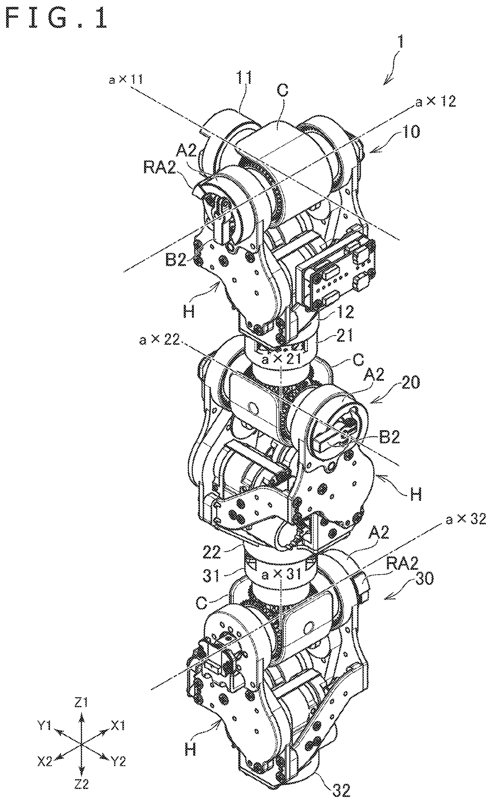
is a perspective view of an upper rear side of a multi-joint device according to the present embodiment.
is a perspective view of an upper front side of the multi-joint device according to the present embodiment.
is a left side view of the multi-joint device according to the present embodiment.
is a rear view of the multi-joint device according to the present embodiment.
is a perspective view of an upper rear side of a first joint mechanism according to the present embodiment.
is a perspective view of an upper front side of the first joint mechanism according to the present embodiment.
is a rear view of the first joint mechanism according to the present embodiment.
is a perspective view of a second bevel gear, a third bevel gear, and the periphery thereof in the first joint mechanism according to the present embodiment.
is a left side view of a first bevel gear and the periphery thereof according to the present embodiment.
is a cross-sectional view taken along line X-X in .
is a perspective view of the first bevel gear according to the present embodiment.
is a perspective view of a movable range defining member mounted on a regulated part illustrated in .
is a left side view of a regulated part that rotates about an axis ax 12 , a regulating part that regulates rotation of the regulated part, and the periphery thereof.
is a left side view of the movable range defining member mounted on the regulating part illustrated in .
DESCRIPTION OF EMBODIMENT
Hereinafter, an embodiment of the present disclosure will be explained with reference to the drawings.
General Overview of Entire Configuration
First, the general overview of the entire configuration of a multi-joint device 1 according to the present embodiment will be explained with reference to to 4 . is a perspective view of an upper rear side of the multi-joint device according to the present embodiment. is a perspective view of an upper front side of the multi-joint device according to the present embodiment. is a left side view of the multi-joint device according to the present embodiment. is a rear view of the multi-joint device according to the present embodiment.
In the following explanation, an arrow X 1 , an arrow X 2 , an arrow Y 1 , an arrow Y 2 , an arrow Z 1 , and an arrow Z 2 in the drawings indicate the right side, the left side, the front side, the rear side, the upper side, and the lower side, respectively. In to 4 , an axis ax 11 and an axis ax 22 extend in the front-rear direction, an axis ax 12 and an axis ax 32 extend in the left-right direction, and an axis ax 21 and an axis ax 31 extend in the up-down direction. It is to be noted that none of these axes in the drawings exists in reality, and these axes are rotation centers for respective parts, which will be explained later. In the following explanation, the attitude of the multi-joint device 1 illustrated in to 4 , is referred to as a “basic attitude.”
In the present embodiment, the multi-joint device 1 includes a first joint mechanism 10 , a second joint mechanism 20 , and a third joint mechanism 30 .
The first joint mechanism 10 includes a connection object part 11 at one end thereof, and a connecting part 12 at the other end thereof. In the first joint mechanism 10 , the connection object part 11 is rotated relatively to the connecting part 12 about the axis ax 11 and about the axis ax 12 which extends in a direction perpendicular to the axis ax 11 . Thus, the first joint mechanism 10 is a generally-called biaxial integrated type.
Likewise, the second joint mechanism 20 includes a connection object part 21 at one end thereof, and a connecting part 22 at the other end thereof. In the second joint mechanism 20 , the connection object part 21 is rotated relatively to the connecting part 22 about the axis ax 21 and about the axis ax 22 which extends in a direction perpendicular to the axis ax 21 . Thus, the second joint mechanism 20 is a generally-called biaxial integrated type. Likewise, the third joint mechanism 30 includes a connection object part 31 at one end thereof, and a connecting part 32 at the other end thereof. In the third joint mechanism 30 , the connection object part 31 is rotated relatively to the connecting part 32 about the axis ax 31 and about the axis ax 32 which extends in a direction perpendicular to the axis ax 31 . Thus, the third joint mechanism 30 is a generally-called biaxial integrated type.
It is to be noted that the term “rotate” in the present description means an action of making a circular movement in either a clockwise direction or a counterclockwise direction about an axis at a circular movement angle of less than 360 degrees.
In to 4 , the connecting part 12 of the first joint mechanism 10 is connected to the connection object part 21 of the second joint mechanism 20 , and the connecting part 22 of the second joint mechanism 20 is connected to the connection object part 31 of the third joint mechanism 30 . In this structure, rotation of the connection object part 21 relative to the connecting part 22 results in rotation of the first joint mechanism 10 relative to the second joint mechanism 20 . In addition, rotation of the connection object part 31 relative to the connecting part 32 results in rotation of the first joint mechanism 10 and the second joint mechanism 20 relative to the third joint mechanism.
[Joint Mechanism]
Next, with reference to to 10 , the details of the first joint mechanism 10 will be explained to exemplify a joint mechanism according to the present embodiment. It is to be noted that a detailed explanation of the second joint mechanism 20 and the third joint mechanism 30 will be omitted because these joint mechanisms have the same configuration and operate in the same manner as the first joint mechanism 10 . It is to be noted that to 10 each illustrate the first joint mechanism 10 in a state where the multi-joint device 1 is in the basic attitude which is illustrated in , etc.
is a perspective view of the upper rear side of the first joint mechanism according to the present embodiment. is a perspective view of the upper front side of the first joint mechanism according to the present embodiment. is a rear view of the first joint mechanism according to the present embodiment. It is to be noted that a gear cover C which is illustrated in to 4 , is not illustrated in to 7 in order to represent bevel gears, which will be explained later. It is to be noted that the gear covers C are intended to inhibit the bevel gears from being viewed from the outside, and to protect the bevel gears against dust or the like.
is a perspective view of a second bevel gear, a third bevel gear, and the periphery thereof in the first joint mechanism according to the present embodiment. is a left side view of a first bevel gear and the periphery thereof. is a cross-sectional view taken along line X-X in .
The first joint mechanism 10 mainly includes a base part 110 and a rotary part 120 . The rotary part 120 rotates relatively to the base part 110 . Specifically, in the first joint mechanism 10 , the rotary part 120 rotates when the base part 110 is fixed to a member that is external to the first joint mechanism 10 , and the base part 110 rotates when the rotary part 120 is fixed to a member that is external to the first joint mechanism 10 . The following explanation describes an example in which the rotary part 120 rotates while the base part 110 is fixed to a member that is external to the first joint mechanism 10 .
The first joint mechanism 10 further includes a support part 130 . Incidentally, when the rotary part 120 rotates about the axis ax 11 , the support part 130 becomes a portion of the base part 110 , and, when the rotary part 120 rotates about the axis ax 12 , the support part 130 becomes a portion of the rotary part 120 , which will be explained in detail later. Specifically, when the rotary part 120 rotates about the axis ax 11 , the support part 130 rotates relative to the rotary part 120 , and, when the rotary part 120 rotates about the axis ax 12 , the support part 130 rotates relative to the base part 110 .
[Joint Mechanism: Rotary Part 120 ]
The rotary part 120 includes the connection object part 11 and a first bevel gear G 1 , as illustrated in . The connection object part 11 and the first bevel gear G 1 are integrally formed. Therefore, the connection object part 11 rotates together with the first bevel gear G 1 . It is to be noted that illustration of the connection object part 11 is omitted in .
The rotation center of the first bevel gear G 1 is the axis ax 11 . A bearing hole h 1 through which a first support shaft 131 of the support part 130 , which will be explained later, is inserted is formed in the center portion of the first bevel gear G 1 . The bearing hole h 1 may be formed to reach the rear surface side of the first bevel gear G 1 (see ).
[Joint Mechanism: Base Part 110 ]
The base part 110 includes an exterior housing H that forms the exterior of the first joint mechanism 10 , a second bevel gear G 2 , and a third bevel gear G 3 . The rotation center of the second bevel gear G 2 and the third bevel gear G 3 is the axis ax 12 .
The second bevel gear G 2 is disposed so as to be engaged with the first bevel gear G 1 , and to rotate about the axis ax 12 , as illustrated in , 10 , or the like.
The second bevel gear G 2 is formed integrally with a spur gear SG 1 , as illustrated in . Upon receiving a driving force from a first motor M 1 which is a driving source, the spur gear SG 1 rotates. The second bevel gear G 2 rotates together with the spur gear SG 1 . A driving force from the first motor M 1 may be inputted to the spur gear SG 1 via a speed reduction gear or the like. The first motor M 1 may be housed in the exterior housing H. It is to be noted that a detailed explanation of the structure and arrangement of the first motor M 1 will be omitted. The same applies to a second motor M 2 , which will be explained later.
A bearing hole h 2 through which a second support shaft 132 of the support part 130 , which will be explained later, is inserted is formed in the center portion of the second bevel gear G 2 . The bearing hole h 2 is formed so as to reach the rear surface side of the spur gear SG 1 (see ).
The third bevel gear G 3 is engaged with the first bevel gear G 1 , as illustrated in , 10 , or the like. Further, the third bevel gear G 3 is disposed so as to face the second bevel gear G 2 in the axis ax 12 direction, and rotates about the axis ax 12 .
The third bevel gear G 3 is formed integrally with a spur gear SG 2 , as illustrated in . Upon receiving a driving force from a second motor M 2 which is a driving source that is different from the first motor M 1 , the spur gear SG 2 rotates. The third bevel gear G 3 rotates together with the spur gear SG 2 . It is to be noted that a driving force from the second motor M 2 may be inputted to the spur gear SG 2 via a speed reduction gear or the like.
A bearing hole h 3 through which a second support shaft 132 of the support part 130 , which will be explained later, is inserted is formed in the center portion of the third bevel gear G 3 (see ).
It is to be noted that or the like illustrates the second bevel gear G 2 including two radially split members. However, this is just an example. The second bevel gear G 2 may be formed of one member. The same applies to the third bevel gear G 3 .
[Joint Mechanism: Support Part 130 ]
The support part 130 includes the first support shaft 131 extending along the axis ax 11 , and the second support shaft 132 extending along the axis ax 12 . The first support shaft 131 and the second support shaft 132 each have a columnar shape or a cylindrical shape.
The support part 130 supports the first bevel gear G 1 , the second bevel gear G 2 , and the third bevel gear G 3 . More specifically, the first support shaft 131 of the support part 130 is inserted through the bearing hole h 1 formed in the first bevel gear G 1 , and supports the first bevel gear G 1 . Also, the second support shaft 132 of the support part 130 is inserted through the bearing hole h 2 formed in the second bevel gear G 2 and the bearing hole h 3 formed in the third bevel gear G 3 , and supports the second bevel gear G 2 and the third bevel gear G 3 . It is to be noted that a bearing or the like (not illustrated) is preferably disposed between the outer circumferential surface of the first support shaft 131 and the inner circumferential surface of the bearing hole h 1 in the first bevel gear G 1 . Likewise, bearings or the like are preferably disposed between the outer circumferential surface of the second support shaft 132 and the inner circumferential surface of the bearing hole h 2 in the second bevel gear G 2 and between the outer circumferential surface of the second support shaft 132 and the inner circumferential surface of the bearing hole h 3 in the third bevel gear G 3 .
The support part 130 is separate from the first bevel gear G 1 , the second bevel gear G 2 , and the third bevel gear G 3 . Specifically, the first bevel gear G 1 is supported by the first support shaft 131 in such a way that the inner circumferential surface of the bearing hole h 1 in the first bevel gear G 1 is rotatable about the axis ax 11 relatively to the outer circumferential surface of the first support shaft 131 . Also, the second bevel gear G 2 is supported by the second support shaft 132 in such a way that the inner circumferential surface of the bearing hole h 2 in the second bevel gear G 2 is rotatable about the axis ax 12 relatively to the outer circumferential surface of the second support shaft 132 . In addition, the third bevel gear G 3 is supported by the second support shaft 132 in such a way that the inner circumferential surface of the bearing hole h 3 in the third bevel gear G 3 is rotatable about the axis ax 12 relatively to the outer circumferential surface of the second support shaft 132 .
The second support shaft 132 is supported by a bearing (not illustrated) that is disposed on an upper right part HR of the exterior housing H and an upper left part HL of the exterior housing H so as to connect the upper right part HR and the upper left part HL, as illustrated in , or the like. It is to be noted the upper right part HR includes a cover part C 2 that covers the spur gear SG 2 , as illustrated in . The cover part C 2 is a part of the exterior housing H, and has a bottomed tubular shape formed along the outer shape of the spur gear SG 2 . The upper left part HL also includes a cover part C 1 that covers the spur gear SG 1 . The cover part C 1 is a part of the exterior housing H, and has a bottomed tubular shape formed along the outer shape of the spur gear SG 1 .
The second support shaft 132 passes through the bearing hole h 2 , and is projected from the rear surface side of the spur gear SG 1 , as illustrated in or the like. In addition, a regulated part B 2 extending in a direction perpendicular to the axis ax 12 is mounted on a projection that is a portion, of the second support shaft 132 , projected from the rear surface side of the spur gear SG 1 . The regulated part B 2 is mounted on the second support shaft 132 so as to rotate together with rotation of the second support shaft 132 about the axis ax 12 . It is to be noted that the details of the regulated part B 2 will be explained later.
In addition, the support part 130 includes an intervening section 135 that is a section where the first support shaft 131 and the second support shaft 132 intersect with each other, and intervenes between the second bevel gear G 2 and the third bevel gear G 3 , as illustrated in , 8 , or the like. With the intervening section 135 , the second bevel gear G 2 and the third bevel gear G 3 are positioned with respect to the extension direction of the axis ax 12 . The intervening section 135 is formed integrally with the first support shaft 131 and the second support shaft 132 .
Further, the intervening section 135 includes a diameter enlarged section 135 a that has a larger diameter than the first support shaft 131 and is integrated with the first support shaft 131 , as illustrated in . A regulating part A 1 extending in a direction perpendicular to the axis ax 11 is formed on the outer circumferential surface of the diameter enlarged section 135 a . It is to be noted that the details of the regulating part A 1 will be explained later.
It is to be noted that, on a side opposite to the diameter enlarged section 135 a in the extension direction of the axis ax 11 , the gear cover C which is illustrated in , etc., but is not illustrated in to 10 , is preferably fixed to the intervening section 135 .
[Joint Mechanism: Rotation about Axis Ax 11 ]
As previously explained, the second bevel gear G 2 rotates upon receiving a driving force outputted from the first motor M 1 , while the third bevel gear G 3 rotates upon receiving a driving force outputted from the second motor M 2 .
If the second bevel gear G 2 rotates clockwise with respect to the X 2 direction, a force F 11 acts upwardly in a portion, of the first bevel gear G 1 , engaged with the second bevel gear G 2 (see ). If the third bevel gear G 3 rotates counterclockwise with respect to the X 2 direction, a force F 22 acts downwardly in a portion, of the first bevel gear G 1 , engaged with the third bevel gear G 3 (see ). With the force F 11 and the force F 22 , the first bevel gear G 1 rotates about the axis ax 11 to an R 1 direction (clockwise direction) which is illustrated in . According to the R 1 direction rotation of the first bevel gear G 1 , the rotary part 120 rotates clockwise with respect to the Y 2 direction.
If the second bevel gear G 2 rotates counterclockwise with respect to the X 2 direction, a force F 12 acts downwardly in a portion, of the first bevel gear G 1 , engaged with the second bevel gear G 2 (see ). If the third bevel gear G 3 rotates clockwise with respect to the X 2 direction, a force F 21 acts upwardly in a portion, of the first bevel gear G 1 , engaged with the third bevel gear G 3 (see ). With the force F 12 and the force F 21 , the first bevel gear G 1 rotates about the axis ax 11 to an R 2 direction (counterclockwise direction) which is illustrated in . According to the R 2 direction rotation of the first bevel gear G 1 , the rotary part 120 rotates counterclockwise with respect to the Y 2 direction.
Thus, if the second bevel gear G 2 and the third bevel gear G 3 rotate oppositely with respect to the same direction, the first bevel gear G 1 rotates about the axis all. As a result, the rotary part 120 rotates about the axis ax 11 relatively to the base part 110 .
[Joint Mechanism: Rotation about Axis Ax 12 ]
If the second bevel gear G 2 rotates clockwise with respect to the X 2 direction, the force F 11 acts upwardly in a portion, of the first bevel gear G 1 , engaged with the second bevel gear G 2 (see ). If the third bevel gear G 3 rotates clockwise with respect to the X 2 direction, the force F 21 acts upwardly in a portion, of the first bevel gear G 1 , engaged with the third bevel gear G 3 (see ). With these upward forces F 11 and F 21 , the first bevel gear G 1 rotates about the axis ax 12 so as to follow the shape of the second bevel gear G 2 and the shape of the third bevel gear G 3 . Accordingly, the rotary part 120 rotates about the axis ax 12 to an R 3 direction which is illustrated in .
If the second bevel gear G 2 rotates counterclockwise with respect to the X 2 direction, the force F 12 acts downwardly in a portion, of the first bevel gear G 1 , engaged with the second bevel gear G 2 (see ). If the third bevel gear G 3 rotates counterclockwise with respect to the X 2 direction, the force F 22 acts downwardly in a portion, of the first bevel gear G 1 , engaged with the third bevel gear G 3 (see ). With these downward forces F 12 and F 22 , the first bevel gear G 1 rotates about the axis ax 12 so as to follow the shape of the second bevel gear G 2 and the shape of the third bevel gear G 3 . Accordingly, the rotary part 120 rotates about the axis ax 12 to an R 4 direction which is illustrated in .
In addition, when the rotary part 120 including the first bevel gear G 1 rotates about the axis ax 12 to the R 3 or R 4 direction illustrated in , the outer circumferential surface of the first support shaft 131 of the support part 130 is pushed against the inner circumferential surface of the bearing hole h 1 in the first bevel gear G 1 . Accordingly, the support part 130 rotates about the axis ax 12 .
[Movable Range of Joint Mechanism]
The present embodiment adopts a configuration of physically regulating the rotational movable ranges of the first joint mechanism 10 about the axis ax 11 and the axis ax 12 . More specifically, the rotational movable range about the axis ax 11 is regulated by the regulating part A 1 , and the rotational movable range about the axis ax 12 is regulated by a regulating part A 2 . A more specific explanation will be given below.
[Movable Range of Joint Mechanism: Rotation about Axis Ax 11 ]
is a perspective view of a first bevel gear according to the present embodiment.
In the first bevel gear G 1 , a center hole h 11 having a larger diameter than the bearing hole h 1 through which the first support shaft 131 is inserted, is formed coaxially with the bearing hole h 1 . A regulated part B 1 is disposed on the inner circumferential surface of the center hole h 11 . The regulated part B 1 rotates about the axis ax 11 together with rotation of the first bevel gear G 1 about the axis ax 11 .
The regulating part A 1 is disposed on the first support shaft 131 of the support part 130 , as illustrated in or the like. The regulating part A 1 is disposed on the extension of the rotation locus of the regulated part B 1 . The regulating part A 1 has a function of regulating rotation of the regulated part B 1 within a first movable range Ra 1 which is illustrated in .
For example, if the first bevel gear G 1 rotates about the axis ax 11 to the R 1 direction which is illustrated in , the regulated part B 1 rotates to the R 1 direction together with the rotation of the first bevel gear G 1 . After rotating by a prescribed angle about the axis ax 11 , the regulated part B 1 comes into contact with the regulating part A 1 . When the regulated part B 1 is caught on the regulating part A 1 in this manner, the rotation of the regulated part B 1 to the R 1 direction is regulated.
If the first bevel gear G 1 rotates about the axis ax 11 to the R 2 direction which is illustrated in , the regulated part B 1 rotates to the R 2 direction together with the rotation of the first bevel gear G 1 . After rotating by a prescribed angle about the axis ax 11 , the regulated part B 1 comes into contact with the regulating part A 1 . When the regulated part B 1 is caught on the regulating part A 1 in this manner, the rotation of the regulated part B 1 to the R 2 direction is regulated.
Rotation of the regulated part B 1 about the axis ax 11 is regulated in this manner, so that rotation of the rotary part 120 about the axis ax 11 relative to the base part 110 is regulated.
In the first joint mechanism 10 according to the present embodiment, a movable range defining member RA 1 is mounted on the regulated part B 1 of the first bevel gear G 1 . is a perspective view of a movable range defining member mounted on the regulated part illustrated in .
The movable range defining member RA 1 is configured to set the movable range of the regulated part B 1 to be narrower than the first movable range Ra 1 which is illustrated in . The movable range defining member RA 1 is separate from the regulated part B 1 , and is preferably attachable to/detachable from the regulated part B 1 .
illustrates an example in which the movable range defining member RA 1 is formed so as to almost completely cover the regulated part B 1 , and has a length in the circumferential direction of the axis ax 11 , longer than the regulated part B 1 . However, the movable range defining member RA 1 is not limited to this example. It is sufficient to dispose the movable range defining member RA 1 in such a way that the movable range of the regulated part B 1 becomes narrower than at least the first movable range Ra 1 illustrated in . For example, the movable range defining member RA 1 may be mounted to cover only one end side, in the circumferential direction of the axis ax 11 , of the regulated part B 1 . The movable range defining member RA 1 is not necessarily formed to cover the regulated part B 1 , and thus, the movable range defining member RA 1 may be disposed apart from the regulated part B 1 in the circumferential direction of the axis ax 11 . In this case, it is preferable that the movable range defining member RA 1 is fixedly mounted on the inner circumferential surface of the center hole h 11 in the first bevel gear G 1 .
In the present embodiment, since the movable range defining member RA 1 is used, the movable range of rotation of the rotary part 120 about the axis ax 11 can be controlled for the purpose of use of the first joint mechanism 10 , etc. Therefore, as a result of use of the first joint mechanism 10 according to the present embodiment, it is not necessary to prepare joint mechanisms having different movable ranges according to respective purposes of use. Consequently, a cost increase can be suppressed.
Further, since the regulated part B 1 is configured to come into contact with the regulating part A 1 according to rotation about the axis ax 11 , the regulated part B 1 may be worn out and deteriorate after a long-term use. In the present embodiment, the movable range defining member RA 1 is mounted so as to cover the regulated part B 1 , so that the regulated part B 1 is inhibited from being worn out or deteriorating. That is, the movable range defining member RA 1 additionally has a function of protecting the regulated part B 1 . If the movable range defining member RA 1 is worn out and deteriorates, the movable range defining member RA 1 can be removed from the regulated part B 1 , and be replaced with a new one. Since the movable range defining member RA 1 is replaceable, it is not necessary to replace the first joint mechanism 10 itself even when the movable range defining member RA 1 is worn out and deteriorates. Thus, a cost increase can be suppressed. It is to be noted that it is sufficient that the movable range defining member RA 1 is separate from at least the regulated part B 1 . The movable range defining member RA 1 include the same material as that of the regulated part B 1 , or may include a material different from the material of the regulated part B 1 .
[Movable Range of Joint Mechanism: Rotation about Axis Ax 12 ]
is a left side view of a regulated part that rotates about the axis ax 12 , a regulating part that regulates rotation of the regulated part, and the periphery thereof.
The regulating part A 2 is disposed in the upper left part HL (cover part C 2 ) of the exterior housing H of the first joint mechanism 10 . The regulating part A 2 is disposed on the extension of the rotation locus of the supported part B 2 . The regulating part A 2 has a function of regulating rotation of the regulated part B 2 within a prescribed movable range. It is preferable that the regulating part A 2 has an arc shape following the shape of the upper left part HL (cover part C 2 ), as illustrated in or the like. The regulating part A 2 regulates the movable range of the regulated part B 2 according to the length of the regulating part A 2 in the circumferential direction of the axis ax 12 . Specifically, when the regulating part A 2 is long in the circumferential direction of the axis ax 12 , the movable range of the regulated part B 2 is narrow. When the regulating part A 3 is short in the circumferential direction of the axis ax 12 , the movable range of the regulated part B 2 is wide.
For example, if the first bevel gear G 1 rotates about the axis ax 12 to the R 3 direction which is illustrated in , the regulated part B 2 rotates to the R 3 direction together with the rotation of the first bevel gear G 1 . Then, after rotating by a prescribed angle about the axis ax 12 , the regulated part B 2 comes into contact with the regulating part A 2 . When the regulated part B 2 is caught on the regulating part A 2 in this manner, the rotation of the regulated part B 2 to the R 3 direction is regulated.
If the first bevel gear G 1 rotates about the axis ax 12 to the R 4 direction which is illustrated in , the regulated part B 2 rotates to the R 4 direction together with the rotation of the first bevel gear G 1 . After rotating by a prescribed angle about the axis ax 12 , the regulated part B 2 comes into contact with the regulating part A 2 . When the regulated part B 2 is caught on the regulating part A 2 in this manner, the rotation of the regulated part B 2 to the R 4 direction is regulated.
As explained so far, rotation of the regulated part B 2 about the axis ax 12 is regulated, whereby rotation of the rotary part 120 relative to the base part 110 about the axis ax 12 is regulated.
In the first joint mechanism 10 according to the present embodiment, a movable range defining member RA 2 is mounted on the regulating part A 2 . is a left side view of a movable range defining member mounted on the regulating part illustrated in .
The movable range defining member RA 2 sets the movable range of the regulated part B 2 to a second movable range Ra 4 that is narrower than a first movable range Ra 3 which is illustrated in . The movable range defining member RA 2 is separate from the regulating part A 2 , and is preferably attachable to/detachable from the regulating part A 2 .
illustrates an example in which the movable range defining member RA 2 is mounted on one end side of the regulating part A 2 in the circumferential direction of the axis ax 12 . However, the movable range defining member RA 2 is not limited to this example. It is sufficient to dispose the movable range defining member RA 2 in such a way that the movable range of the regulated part B 2 becomes narrower than at least the first movable range Ra 3 illustrated in . For example, the movable range defining members RA 2 may be mounted on both ends of the regulating part A 2 in the circumferential direction of the axis ax 12 . Alternatively, the movable range defining member RA 2 may be disposed apart from the regulating part A 2 in the circumferential direction of the axis ax 12 . In this case, on the extension of the rotation locus of the regulated part B 2 about the axis ax 12 , the movable range defining member RA 2 may be fixed to the exterior housing H of the base part 110 , for example.
In the present embodiment, since the movable range defining member RA 2 is used, the movable range of rotation of the rotary part 120 about the axis ax 12 can be controlled according to the purpose of use of the first joint mechanism 10 , etc. Therefore, as a result of use of the first joint mechanism 10 according to the present embodiment, it is not necessary to prepare joint mechanisms having different movable ranges according to respective purposes of use. Consequently, a cost increase can be suppressed.
Further, since the regulated part B 2 comes into contact with the regulating part A 2 according to rotation of the regulated part B 2 about the axis ax 12 , the regulating part A 2 may be worn out and deteriorate after a long-term use. In the present embodiment, since the movable range defining member RA 2 is mounted so as to cover a portion of the regulating part A 2 with which the regulated part B 2 comes into contact, the regulating part A 2 is inhibited from being worn out or deteriorating. That is, the movable range defining member RA 2 additionally has a function of protecting the regulating part A 2 . If the movable range defining member RA 2 is worn out and deteriorates, the movable range defining member RA 2 may be removed from the regulating part A 2 , and be replaced with a new one. Since the movable range defining member RA 2 is replaceable, it is not necessary to replace the first joint mechanism 10 itself even when the movable range defining member RA 2 is worn out and deteriorates. Thus, a cost increase can be suppressed.
[Others]
The first joint mechanism 10 has been explained with reference to to 14 . It is preferable that the second joint mechanism 20 and the third joint mechanism 30 also have the same configuration. That is, it is preferable that the first joint mechanism 10 , the second joint mechanism 20 , and the third joint mechanism 30 are identical to each other. Further, the presence/absence of the movable range defining members RA 1 and RA 2 is preferably decided according to the purpose of use or according to a position. In the multi-joint device 1 illustrated in to 4 , the movable range defining member RA 2 is mounted on the regulating part A 2 in each of the first joint mechanism 10 and the third joint mechanism 30 , while no movable range defining member is mounted on the regulating part A 2 of the second joint mechanism 20 . In this configuration, the rotational movable range of the first joint mechanism 10 about the axis ax 12 is equal to the rotational movable range of the third joint mechanism 30 about the axis ax 32 . On the other hand, the rotational movable range of the second joint mechanism 20 about the axis ax 22 is wider than the rotational movable range of the first joint mechanism 10 about the axis ax 12 . It is to be noted that the presence/absence of the movable range defining member RA 1 which is mounted on the regulated part B 1 of the first bevel gear G 1 is also preferably decided according to the purpose of use or according to a position. This is not illustrated in the drawings though.
It is to be noted that the multi-joint device 1 is preferably used for a human or animal-form robot that can walk on two legs or four legs, for example. In a case where the multi-joint device 1 including a plurality of joint mechanisms is used for an arm of a human form robot, for example, one of the joint mechanisms is used as a shoulder joint, and another joint mechanism is used as an elbow joint.
The multi-joint device 1 including the three joint mechanisms has been explained in the present embodiment. However, the number of joint mechanisms is not limited, and thus, the number may be one, two, four, or greater.
In the multi-joint device 1 illustrated in , etc., any other joint mechanism may be additionally connected to the connection object part 11 of the first joint mechanism 10 or the connecting part 32 of the third joint mechanism 30 . Further, an end effector of any type may be additionally connected to the connection object part 11 or the connecting part 32 .
In the above-mentioned embodiment, the second bevel gear G 2 and the third bevel gear G 3 rotate in the same direction or in the opposite directions, when viewed from the same direction. Alternatively, either the second bevel gear G 2 or the third bevel gear G 3 may be driven to rotate while the other gear is stopped. In this case, the rotary part 120 rotates relatively to the base part 110 so as to be twisted with respect to the axis ax 11 and the axis ax 12 , but a detailed explanation thereof will be omitted.
In addition, it is preferable that the regulating part A 2 is formed so as to come into surface-contact with the regulated part B 2 . If so, in a state where the movable range defining member RA 2 is not mounted, the regulating part A 2 receives, by a surface thereof, a shock caused by the contact with the regulated part B 2 , and a local force is inhibited from acting on the regulating part A 2 . As a result, the durability of the regulating part A 2 is improved, and the life of the regulating part A 2 is increased. In addition, it is preferable that the movable range defining member RA 2 is also formed so as to come into surface-contact with the regulated part B 2 . If so, the movable range defining member RA 2 receives, by a surface thereof, a shock caused by the contact with the regulated part B 2 , and a local force is inhibited from acting on the movable range defining member RA 2 . As a result, the durability of the movable range defining member RA 2 is improved, and the life of the movable range defining member RA 2 is increased.
In the present embodiment, the movable range defining member RA 2 is mounted on the regulating part A 2 that is disposed on the rear surface side of the second bevel gear G 2 and the spur gear SG 1 , whereby an access to the movable range defining member RA 2 from the outside can be easily made. That is, it is easy to attach/detach the movable range defining member RA 2 to/from the regulating part A 2 .
In the above-mentioned embodiment, the regulated part B 1 is disposed on the inner circumferential surface of the center hole h 11 in the first bevel gear G 1 . Alternatively, the regulated part B 1 may be disposed on the rear surface side of the first bevel gear G 1 . If so, the regulating part A 1 is preferably disposed on a projection that is a portion, of the first support shaft 131 , projected from the rear surface side of the first bevel gear G 1 . In this case, however, it is difficult to connect another member to the connection object part 11 of the rotary part 120 . That is, when the configuration of the present embodiment in which the regulated part B 1 is disposed on the inner circumferential surface of the center hole h 11 in the first bevel gear G 1 is adopted, a structure in which another member can be easily connected to the rotary part 120 of the first joint mechanism 10 , is realized.
In the present embodiment, the movable range defining member RA 1 is mounted on the regulated part B 1 . Alternatively, the movable range defining member RA 1 may be mounted on the regulating part A 1 . Also, in the present embodiment, the movable range defining member RA 2 is mounted on the regulating part A 2 . Alternatively, the movable range defining member RA 2 may be mounted on the regulated part B 2 .
Incidentally, in the present embodiment, the base part 110 is fixed while the rotary part 120 rotates. However, it is sufficient that the rotary part 120 rotates relatively to the base part 110 . That is, if the rotary part 120 is fixed, the base part 110 may rotate. In this case, the regulated part B 1 functions as a member for regulating rotation of the regulating part A 1 , while the regulated part B 2 functions as a member for regulating rotation of the regulating part A 2 .
Figures (13)
Citations
This patent cites (15)
- US3419158
- US4828094
- US10877508
- US10919159
- US2019/0171247
- US2023/0137602
- US107738259
- US112008741
- US6228194
- US59166493
- US0413285
- USH0413285
- USH10202574
- US2003117858
- US201998463