Abstract
A power tool includes a spindle, a housing, a cover body configured to be removably mounted to the housing, a first engagement part provided on or in the cover body, and a second engagement part provided on or in the housing. The cover body includes an upper plate part and an outer peripheral part. The second engagement part is movable between an engagement position and a disengagement position. The first and second engagement parts are configured to restrict rotation of the cover body around the drive axis relative to the housing by engaging with each other. The first engagement part is (i) at a same location as or radially outward of the outer peripheral part of the cover body in a radial direction orthogonal to the drive axis, and (ii) between an upper end and a lower end of the cover body in the up-down direction.
Claims (19)
1. A power tool, comprising: a spindle that (i) extends along a drive axis that defines an up-down direction of the power tool and (ii) has a lower end portion that is configured such that a tool accessory is removably mounted thereto; a housing that houses the spindle with the lower end portion exposed to an outside of the housing; a cover body that is (i) configured to be removably mounted to the housing to partially cover the tool accessory mounted to the lower end portion of the spindle, and (ii) includes (a) an upper plate part that is configured to be arranged above the tool accessory and (b) an outer peripheral part that extends along an outer edge of the upper plate part and protrudes downward from the outer edge; a first engagement part that is provided on or in the cover body; and a second engagement part that (i) is provided on or in the housing and (ii) is movable between (a) an engagement position at which the second engagement part engages with the first engagement part and (b) a disengagement position at which the second engagement part is not engageable with the first engagement part, wherein: the first engagement part and the second engagement part are configured to restrict rotation of the cover body around the drive axis relative to the housing by engaging with each other, the first engagement part is (ii) at a same location as the outer peripheral part or radially outward of the outer peripheral part in a radial direction that is orthogonal to the drive axis, and (ii) between an upper end and a lower end of the cover body in the up-down direction, and the first engagement part is configured as a protruding part that protrudes radially outward from the upper plate part or the outer peripheral part of the cover body.
18. A power tool, comprising: a spindle that (i) extends along a drive axis that defines an up-down direction of the power tool, and (ii) has a lower end portion that is configured such that a tool accessory is removably mounted thereto; a housing that houses the spindle with the lower end portion exposed to an outside of the housing; a cover body that (i) is configured to be removably mounted to the housing to partially cover the tool accessory mounted to the lower end portion of the spindle, and (ii) includes (a) an upper plate part that is configured to be arranged above the tool accessory and (b) an outer peripheral part that extends along an outer edge of the upper plate part and protrudes downward from the outer edge; a rail that (i) has an arcuate shape, (ii) protrudes radially outward from the upper plate part or the outer peripheral part of the cover body, and (iii) is entirely located radially outward from the upper plate part or the outer peripheral part of the cover body; and a lever that (i) is configured to be externally manipulated by a user and (ii) is supported by the housing to be movable between (i) an engagement position at which the lever engages with the rail and (b) a disengagement position at which the lever is not engageable with the rail, wherein the rail and the lever are configured to restrict rotation of the cover body around the drive axis relative to the housing by engaging with each other.
Show 17 dependent claims
2. The power tool as defined in claim 1 , wherein the second engagement part is a lever that is linearly movable substantially in parallel to the drive axis.
3. The power tool as defined in claim 2 , wherein: the protruding part has at least one recess or hole that extends in the up-down direction, and the second engagement part has a projection that is configured to engage with the at least one recess or the hole when the second engagement part is at the engagement position.
4. The power tool as defined in claim 3 , wherein the lever includes (i) a manipulation part that is configured to be externally manipulated by a user above the housing, (ii) the projection, and (iii) a connection part that connects the manipulation part and the projection.
5. The power tool as defined in claim 4 , wherein the connection part is at least partially within the housing.
6. The power tool as defined in claim 4 , wherein the projection is configured to be engaged with the protruding part of the cover body from below when the lever is at the engagement position.
7. The power tool as defined in claim 1 , wherein the second engagement part is a rotary lever that is configured to be externally manipulated by a user.
8. The power tool as defined in claim 7 , wherein the second engagement part is movable within a plane that is substantially orthogonal to the drive axis.
9. The power tool as defined in claim 8 , wherein: the protruding part has at least one recess that is recessed radially inward from an outer edge of the protruding part; and the second engagement part has a projection that is configured to be engaged with the recess when the second engagement part is at the engagement position.
10. The power tool as defined in claim 1 , wherein the protruding part is configured to restrict movement of the cover body relative to the housing in a first direction that is different from a circumferential direction around the drive axis by engaging with one or both of the second engagement part and the housing.
11. The power tool as defined in claim 10 , wherein: the housing has a groove, and the protruding part is configured to restrict movement of the cover body relative to the housing in the first direction by being fitted in the groove.
12. The power tool as defined in claim 10 , wherein the second engagement part is configured to restrict (i) rotation of the cover body relative to the housing and (ii) movement of the cover body relative to the housing in the first direction by pressing the protruding part against the housing when the second engagement part is at the engagement position.
13. The power tool as defined in claim 1 , wherein the protruding part is an arcuate rail.
14. The power tool as defined in claim 1 , further comprising a biasing member that is configured to bias the second engagement part toward the engagement position.
15. The power tool as defined in claim 1 , wherein the first engagement part is formed separately from the cover body and fixed to the cover body.
16. The power tool as defined in claim 1 , wherein a lower end of the second engagement part is at a same location as or above a lower end of the cover body in the up-down direction when the second engagement part is at the engagement position and when the second engagement part is at the disengagement position.
17. The power tool as defined in claim 16 , wherein an entirety of the second engagement part is between an upper end and the lower end of the cover body in the up-down direction when the second engagement part is at the engagement position and when the second engagement part is at the disengagement position.
19. The power tool as defined in claim 18 , wherein the rail is configured to restrict movement of the cover body relative to the housing in a first direction that is different from a circumferential direction around the drive axis by being engaged with one or both of the lever and the housing.
Full Description
Show full text →
CROSS-REFERENCE TO RELATED APPLICATION
The present application claims priority to Japanese patent application Nos. 2022-187779 and 2022-187780 filed on Nov. 24, 2022, the contents of which are hereby fully incorporated herein by reference.
TECHNICAL FIELD
The present disclosure relates to a power tool. More specifically, the present disclosure relates to a power tool that includes a cover that partially covers a tool accessory mounted to a spindle.
BACKGROUND
Some power tools (e.g., power tools that rotate or oscillate a tool accessory) are provided with a cover that partially covers a tool accessory mounted to a lower end portion of a spindle in order to suppress scattering of dust and sparks that are generated during a processing operation. In order to facilitate handling of a power tool in a narrow space, it is preferable that the power tool is small in size in an axial direction of the spindle. Accordingly, in order to reduce the size of the spindle in the axial direction, various improvements in a mounting structure of the cover have been proposed. For example, European Patent No. 2189244 discloses a grinder that has a lever that is disposed radially outward of a protection hood (cover) and configured to engage with the protection hood.
SUMMARY
In the above-described grinder, the protection hood has a disc-like part that is placed above a tool accessory and an edge part that is connected to an outer edge of the disc-like part and surrounds an edge of the tool accessory. The lever is disposed radially outward of the protection hood and configured to engage with a recess that is formed in a portion of the edge part of the protection hood that is below the tool accessory. Such a cover mounting structure leaves room for further improvement.
It is accordingly a non-limiting object of the present disclosure to provide an improvement in a structure of mounting a cover for a tool accessory to a power tool.
A non-limiting aspect of the present disclosure herein provides a power tool that includes a spindle, a housing, a cover body, a first engagement part and a second engagement part. The power tool of this aspect may include a rotary tool (e.g., a grinder, a cutter and, a circular saw) that is configured to rotate a tool accessory around a drive axis, and an oscillating tool (a so-called multi-tool) that is configured to oscillate (reciprocally pivot) a tool accessory about a drive axis.
The spindle extends along a drive axis that defines an up-down direction of the power tool. The spindle has a lower end portion that is configured such that a tool accessory is removably mounted thereto. The housing houses the spindle with the lower end portion of the spindle exposed to an outside of the housing. The cover body is configured to be removably mounted to the housing to partially cover the tool accessory mounted to the lower end portion of the spindle. The cover body includes an upper plate part and an outer peripheral part (outer circumferential part). The upper plate part is configured to be arranged above the tool accessory. The outer peripheral part extends along an outer edge of the upper plate part and protrudes downward from the outer edge of the upper plate part. The first engagement part is provided on or in the cover body. The second engagement part is provided on or in the housing. The second engagement part is movable between (a) an engagement position, at which the second engagement part engages with the first engagement part, and (b) a disengagement position, at which the second engagement part is not engageable with the first engagement part. The first engagement part and the second engagement part are configured to restrict rotation of the cover body around the drive axis relative to the housing by engaging with each other. The first engagement part is at a same location as the outer peripheral part of the cover body or radially outward of the outer peripheral part of the cover body in a radial direction that is orthogonal to the drive axis. The first engagement part is between upper end and a lower end of the cover body in the up-down direction. For example, if the first engagement part is a recess or hole formed in the outer peripheral part, the first engagement part may be regarded as being “at the same location as the outer peripheral part in the radial direction”. A position that is at a same level as the upper end and a position that is at a same level as the lower end in the up-down direction can be regarded as being “between the upper end and the lower end of the cover body in the up-down direction”.
The power tool of this aspect is configured such that rotation of the cover body is restricted by the first engagement part provided on/in the cover body and the second engagement part provided on/in the housing that are engaged with each other. Further, the first engagement part is between the upper end and the lower end of the cover body in the up-down direction. Thus, the first engagement part does not protrude upward or downward from the cover body. Therefore, compared with a structure in which the first engagement part protrudes upward or downward from the cover body, the size of the entire power tool with the second engagement part in the up-down direction can be made smaller.
Another non-limiting aspect of the present disclosure herein provides a power tool that includes a spindle, a housing, a cover body, a rail and a lever. An example of the power tool of this aspect is the same as an example of the power tool of the above-described aspect.
The spindle extends along a drive axis that defines an up-down direction of the power tool. The spindle has a lower end portion that is configured such that a tool accessory is removably mounted thereto. The housing houses the spindle with the lower end portion of the spindle exposed to an outside of the housing. The cover body is configured to be removably mounted to the housing and to partially cover the tool accessory mounted to the lower end portion of the spindle. The cover body includes an upper plate part and an outer peripheral part (outer circumferential part). The upper plate part is configured to be arranged above the tool accessory. The outer peripheral part extends along an outer edge of the upper plate part and protrudes downward from the outer edge. The rail has an arcuate shape, and protrudes radially outward from the upper plate part or the outer peripheral part of the cover body. The lever is configured to be externally manipulated by a user. The lever is supported by the housing to be movable between (a) an engagement position, at which the lever engages with the rail, and (b) a disengagement position, at which the lever is not engageable with the rail. The rail and the lever are configured to restrict rotation of the cover body around the drive axis relative to the housing by engaging with each other.
The power tool of this aspect is configured such that rotation of the cover body is restricted by the rail provided on the cover body and the lever provided on the housing. Further, the arcuate rail protrudes radially outward from the upper plate part or the outer peripheral part of the cover body. Therefore, compared with a structure in which the rail protrudes upward or downward from the cover body, the size of the entire power tool with the lever in the up-down direction can be made smaller.
BRIEF DESCRIPTION OF THE DRAWINGS
is a perspective view of a grinder of a first embodiment of the present disclosure.
is a sectional view of the grinder.
is a partial, enlarged view of .
is a perspective view of a cover.
is a perspective view of a front end portion of the grinder.
is a partial, exploded perspective view of the grinder with a tool accessory and the cover removed therefrom.
is a partial, left side view of the grinder with a lever placed in an engagement position and with the cover removed therefrom.
is a sectional view showing a rail and the lever placed in the engagement position.
is a partial, left side view of the grinder with the lever placed in a disengagement position and with the cover removed therefrom.
is a sectional view showing the rail and the lever placed in the disengagement position.
is a partial, left side view showing a grinder of a second embodiment, with a lever placed in the engagement position and with a cover removed therefrom.
is a partial, sectional view showing a grinder of a third embodiment, with a lever placed in the engagement position.
is a perspective view of a cover.
is an enlarged perspective view showing a rail engagement part and its vicinity.
is a partial, exploded perspective view of the grinder with the tool accessory and the cover removed therefrom.
is a partial, sectional view of the grinder, with the lever placed in the disengagement position.
is a partial, perspective view showing a grinder of a fourth embodiment.
is a perspective view of a cover.
is a bottom view of the grinder, with a lever placed in the engagement position.
is a partial, exploded perspective view of the grinder with the tool accessory and the cover removed therefrom.
is a bottom view of the grinder, with the lever placed in the disengagement position.
is a partial, sectional view showing a grinder of a fifth embodiment, with a lever placed in the engagement position.
is a perspective view of a cover.
is a sectional view showing a rail and the lever placed in the engagement position.
is a partial, perspective view of the grinder.
is a partial, exploded perspective view of the grinder with the tool accessory and the cover removed therefrom.
is a partial, sectional view of the grinder with the lever placed in the disengagement position.
is a sectional view showing the rail and the lever placed in the disengagement position.
is a partial, sectional view showing a grinder of a sixth embodiment, with a lever placed in the engagement position.
is a partial, perspective view of the grinder.
is a partial, exploded perspective view of the grinder with the tool accessory and a cover removed therefrom.
is a sectional view showing a rail and the lever placed in the engagement position.
is a partial, sectional view of the grinder with the lever placed in the disengagement position.
is a sectional view showing the rail and the lever placed in the disengagement position.
is a partial, sectional view showing a grinder of a seventh embodiment, with a latch placed in the engagement position.
is a bottom view of the grinder, with the latch placed in the engagement position.
is a sectional view showing a cover and the latch placed in the disengagement position.
is a bottom view of the grinder with another cover mounted thereto.
is a bottom view of the grinder with yet another cover mounted thereto.
DETAILED DESCRIPTION OF THE EMBODIMENTS
In a non-limiting embodiment according to the present disclosure, the first engagement part may be configured as a protruding part that protrudes radially outward from the upper plate part or the outer peripheral part of the cover body. According to this embodiment, the freedom of design of the engagement structure of the first and second engagement parts can be enhanced.
In addition or in the alternative to the preceding embodiment, the second engagement part may be a lever that is linearly movable substantially in parallel to the drive axis. According to this embodiment, rotation of the cover body can be effectively restricted by cooperation between the protruding part provided on the cover body and a simple lever provided on the housing.
In addition or in the alternative to the preceding embodiments, the protruding part may have at least one recess or hole that extends in the up-down direction. The second engagement part may have a projection that is configured to engage with the recess or the hole when the second engagement part is at the engagement position. According to this embodiment, rotation of the cover body relative to the housing can be reliably restricted.
In addition or in the alternative to the preceding embodiments, the lever may include (i) a manipulation part that is configured to be externally manipulated by a user above the housing, (ii) the projection, and (iii) a connection part that connects the manipulation part and the projection. According to this embodiment, the user can easily manipulate the lever.
In addition or in the alternative to the preceding embodiments, the connection part may be at least partially within the housing. According to this embodiment, the possibility that the lever is affected by an unintended external force can be reduced.
In addition or in the alternative to the preceding embodiments, the projection may be configured to be engaged with the protruding part of the cover body from below when the lever is at the engagement position. According to this embodiment, a user can move the lever from the engagement position to the disengagement position by pushing the manipulation part downward. The user can thus manipulate the lever more easily, compared with a structure that requires pulling the manipulation part upward.
In addition or in the alternative to the preceding embodiments, the second engagement part may be a rotary lever that is configured to be externally manipulated by a user. According to this embodiment, the lever can be easily manipulated.
In addition or in the alternative to the preceding embodiments, the second engagement part may be movable within or along a plane that is substantially orthogonal to the drive axis. According to this embodiment, the size of the second engagement part in the up-down direction can be reliably reduced.
In addition or in the alternative to the preceding embodiments, the protruding part may have at least one recess that is recessed radially inward from an outer edge of the protruding part. The second engagement part may have a projection that is configured to be engaged with the recess when the second engagement part is at the engagement position. According to this embodiment, rotation of the cover body relative to the housing can be reliably restricted.
In addition or in the alternative to the preceding embodiments, the protruding part may be configured to restrict movement of the cover body relative to the housing in a first direction, which is different from a circumferential direction around the drive axis, by engaging with one or both of the second engagement part and the housing. According to this embodiment, the protruding part provided on the cover body can restrict (i) movement (rotation) of the cover body relative to the housing in the circumferential direction and (ii) movement of the cover body relative to the housing in the first direction that is different from the circumferential direction around the drive axis. Thus, the protruding part can perform two functions of (i) properly positioning the cover body in the circumferential direction and (ii) suppressing looseness or a play in the first direction. Therefore, compared with a case in which these two functions are achieved respectively by two separate (individual, discrete) structures, a space required in the power tool can be reduced and the power tool can be simplified in structure.
In addition or in the alternative to the preceding embodiments, the housing may have a groove. The protruding part may be configured to restrict movement of the cover body relative to the housing in the first direction by being fitted in the groove. According to this embodiment, the cover body can be effectively positioned in the circumferential direction. In addition, the looseness or the play can be reduced by cooperation between the protruding part provided on the cover body and the second engagement part and the groove that are provided in the housing.
In addition or in the alternative to the preceding embodiments, the second engagement part may be configured to restrict (i) rotation of the cover body relative to the housing and (ii) movement of the cover body relative to the housing in the first direction by pressing the protruding part against the housing when the second engagement part is at the engagement position. According to this embodiment, the cover body can be effectively positioned in the circumferential direction and the looseness or the play can be reduced by cooperation between the protruding part, the second engagement part and the housing.
In addition or in the alternative to the preceding embodiments, the power tool may further include a biasing member that is configured to bias the second engagement part toward the engagement position. According to this embodiment, engagement between the first engagement part and the second engagement part can be maintained by the biasing force of the biasing member.
In addition or in the alternative to the preceding embodiments, the first engagement part may be formed separately (discretely, individually) from the cover body and fixed to the cover body. According to this embodiment, the cover body and the first engagement part, which have been formed separately, can be fixed together afterwards. Such a configuration facilitates manufacturing, compared with a case in which the cover body and the first engagement part are integrally formed together from the beginning.
In addition or in the alternative to the preceding embodiments, a lower end of the second engagement part may be at a same location as or above a lower end of the cover body in the up-down direction when the second engagement part is at the engagement position and when the second engagement part is at the disengagement position. According to this embodiment, the second engagement part does not protrude downward from the cover body. Therefore, the size of the entire power tool including the second engagement part can be reduced in the up-down direction. Further, the possibility that the second engagement part is affected by an unintended external force can be reduced.
In addition or in the alternative to the preceding embodiments, the second engagement part may be between an upper end and the lower end of the cover body in the up-down direction both in the engagement position and in the disengagement position. According to this embodiment, the second engagement part does not protrude upward and downward from the cover body. Therefore, the possibility that the second engagement part is affected by an unintended external force can be further reduced.
In addition or in the alternative to the preceding embodiments, the protruding part may be an arcuate rail. The rail may be configured to restrict movement of the cover body relative to the housing in a first direction that is different from a circumferential direction around the drive axis by being engaged with one or both of the lever and the housing. According to this embodiment, the cover body can be effectively positioned in the circumferential direction and the looseness or the play can be reduced by cooperation between the rail and one or both of the lever and the housing.
Representative, non-limiting embodiments of the present disclosure are now specifically described with reference to the drawings. In the following embodiments, a hand-held electric disc grinder (hereinafter simply referred to as a grinder) is described as a representative example of a power tool of the present disclosure. The grinder is also a representative example of a rotary tool that is configured to rotationally drive the tool accessory.
First Embodiment
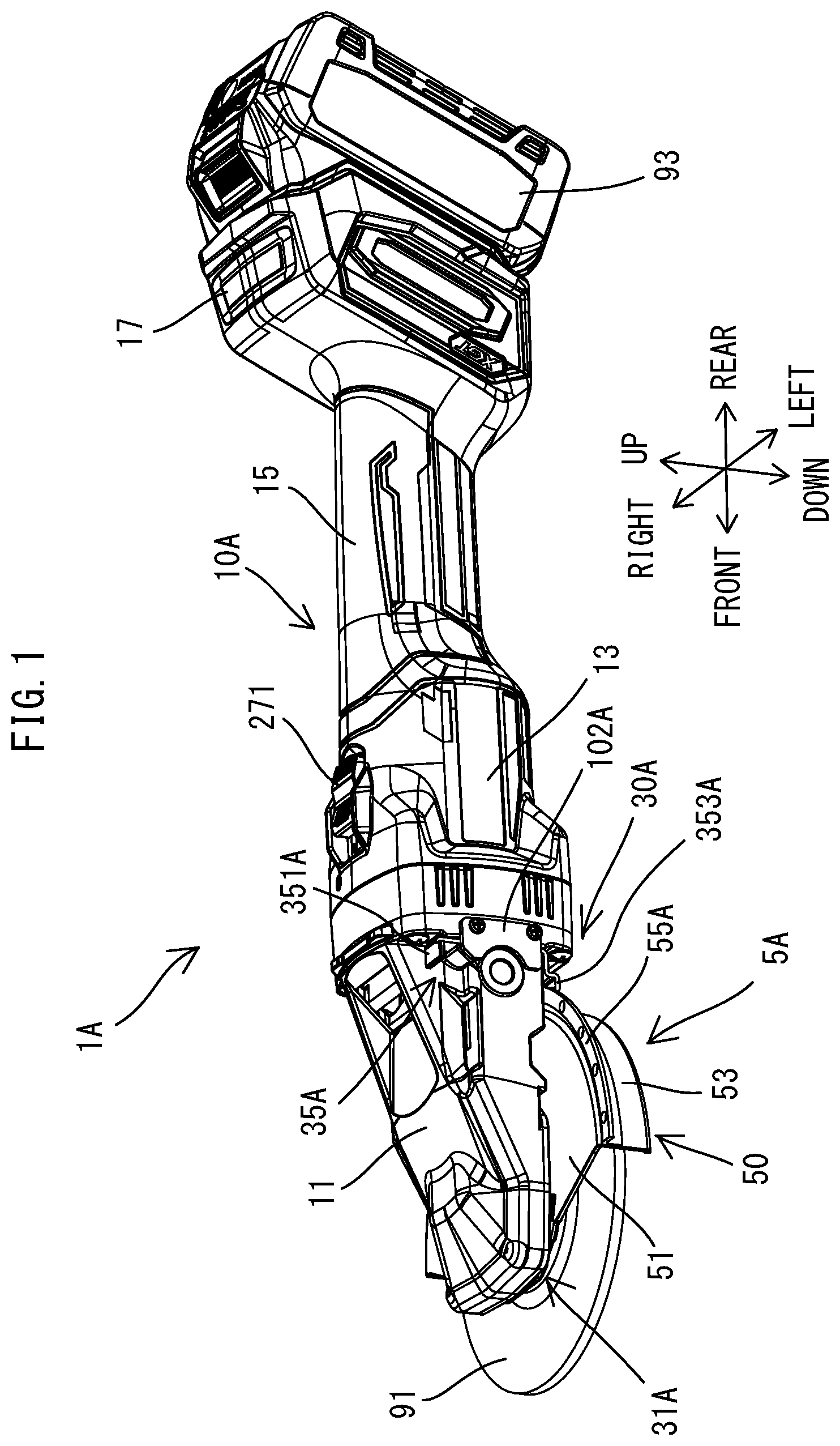
A grinder 1 A according to a first embodiment is now described with reference to to 10 .
The general structure of the grinder 1 A is now described. As shown in , the grinder 1 A includes a motor 21 , a spindle 25 that is operably coupled to the motor 21 , and a housing 10 A that houses the motor 21 and the spindle 25 . The housing 10 A has an elongate hollow body and forms an outer shell of the grinder 1 A. The motor 21 is arranged such that a rotational axis RX of an output shaft 215 of the motor 21 extends substantially in parallel to a longitudinal axis of the housing 10 A. The spindle 25 is disposed within one end portion of the housing 10 A in its longitudinal direction. The spindle 25 is supported within the housing 10 A so as to be rotatable around a drive axis DX. The drive axis DX crosses the rotational axis RX of the output shaft 215 . More specifically, the drive axis DX intersects the rotational axis RX at a substantially right angle.
One axial end portion of the spindle 25 is exposed to the outside from the housing 10 A. A tool accessory 91 is removably mounted to this end portion of the spindle 25 . A portion of the tool accessory 91 is covered by a cover 5 A that is mounted (coupled) to the housing 10 A.
When the spindle 25 is rotationally driven around the drive axis DX by the motor 21 , the tool accessory 91 is rotated, and a processing operation is performed on a workpiece. The tool accessory 91 that can be mounted to the grinder 1 A includes a grinding wheel, a cutting wheel, a blade, a rubber pad and a brush. The grinding wheel, the cutting wheel and the blade are non-limiting examples of the tool accessory 91 having a disc-like shape. A user selects the tool accessory 91 that is suitable for a desired operation and mounts it to the grinder 1 A. The grinder 1 A is capable of performing grinding, polishing, cutting or other similar operation on a workpiece, depending on the kind of the selected tool accessory 91 .
The structure of the grinder 1 A is now described in detail. In the following description, for the sake of convenience, the extending direction of the drive axis DX is defined as an up-down direction of the grinder 1 A. In the up-down direction, the side on which the tool accessory 91 is located is defined as a lower side of the grinder 1 A, and the opposite side is defined as an upper side of the grinder 1 A. The extending direction of the rotational axis RX of the output shaft 215 is defined as a front-rear direction of the grinder 1 A. In the front-rear direction, the side on which the spindle 25 is located is defined as a front side of the grinder 1 A, and the opposite side is defined as a rear side of the grinder 1 A. A direction that is orthogonal to the up-down direction and the front-rear direction is defined as a left-right direction of the grinder 1 A. Further, any direction that is orthogonal to the drive axis DX is defined as a radial direction. In the radial direction, a direction away from the drive axis DX is defined as a radially outward direction, and a direction toward the drive axis DX is defined as a radially inward direction.
First, the structure of the housing 10 A is described.
As shown in , the housing 10 A includes a driving-mechanism housing part 11 , a motor housing part 13 , a handle part 15 and a controller housing part 17 , which are arranged in this order from the front to the rear. The driving-mechanism housing part 11 houses the spindle 25 and an intermediate shaft 23 . The driving-mechanism housing part 11 may also be referred to as a gear housing. The driving-mechanism housing part 11 forms a front end portion of the housing 10 A. The motor housing part 17 houses the motor 21 and a fan 22 . The handle part 15 is configured to be held by a user. The handle part 15 may also be referred to as a grip part. The controller housing part 17 houses a controller 29 . The controller housing part 17 forms a rear end portion of the housing 10 A.
Elements (mechanisms) disposed within the housing 10 A are now described.
The output shaft 215 of the motor 21 is supported within the motor housing part 13 so as to be rotatable around the rotational axis RX. The fan 22 is fixed to a portion of the output shaft 215 that protrudes forward from a stator 211 . The fan 22 integrally rotates with the output shaft 215 .
As shown in , the spindle 25 is supported within the driving-mechanism housing part 11 so as to be rotatable around the drive axis DX. A driven gear 250 is fixed onto an upper portion of the spindle 25 . A lower end portion of the spindle 25 protrudes downward from the housing 10 A. The lower end portion of the spindle 25 is configured as a tool mounting part 253 to which the tool accessory 91 is removably mounted (coupled). In this embodiment, an outer peripheral surface of the tool mounting part 253 is threaded and the tool accessory 91 can be fixed to the tool mounting part 253 by a lock nut 254 . The method of mounting the tool accessory 91 to the spindle 25 is not limited to this, but any known method may be employed.
The grinder 1 A is provided with the cover 5 A for protecting a user from dust and sparks that are generated during a processing operation performed by the tool accessory 91 on a workpiece. The cover 5 A is configured to be removably mounted (coupled) to the housing 10 A such that the cover 5 A partially covers the tool accessory 91 mounted to the tool mounting part 253 of the spindle 25 . The cover 5 A may also be referred to as a wheel cover, a wheel guard, a disc cover, a protection cover or a protection hood. The cover 5 A is described below in further detail.
As shown in , the intermediate shaft 23 is operably connected to the motor 21 and the spindle 25 and transmits rotational driving force of the motor 21 to the spindle 25 . Specifically, the intermediate shaft 23 is coaxial with the output shaft 215 of the motor 21 and supported within the driving-mechanism housing part 11 so as to be rotatable around the rotational axis RX. A rear end portion of the intermediate shaft 23 is engaged with a front end portion of the output shaft 215 via a connecting member, so that the intermediate shaft 23 integrally rotates with the output shaft 215 . A drive gear 230 is provided on a front end portion of the intermediate shaft 23 . The drive gear 230 is engaged with the driven gear 250 . Bevel gears are employed as the drive gear 230 and the driven gear 250 .
With the above-described structure, when the motor 21 is driven, the spindle 25 is rotated around the drive axis DX via the intermediate shaft 23 , and the tool accessory 91 fixed to the tool mounting part 253 is integrally rotated with the spindle 25 . The rotational driving force of the motor 21 may however be transmitted to the spindle 25 via any mechanism other than the intermediate shaft 23 .
As shown in , a switch 27 is housed within the handle part 15 . The switch 27 is for starting the motor 21 . In this embodiment, the motor 21 is energized and driven while the switch 27 is ON. A switch knob 271 , which is configured to turn On and OFF the switch 27 is provided on the housing 10 A. More specifically, the switch knob 271 is supported on an upper portion of the motor housing part 13 so as to be externally manipulated by the user and to be movable between an ON position and an OFF position. The switch knob 271 is normally held in the OFF position. The switch knob 271 is connected to the switch 27 via a connecting member 272 . The switch 27 is switched from OFF to ON when the user moves the switch knob 271 from the OFF position to the ON position.
The controller 29 , which is configured to control operation of the grinder 1 A, is housed within the controller housing part 17 . The controller 29 includes a control circuit and is electrically connected to the motor 21 and the switch 27 . In this embodiment, the controller 29 is configured to control driving of the motor 21 (energization to the motor 21 ) according to ON/OFF of the switch 27 .
A battery mounting part 18 is provided in the controller housing part 17 . A rechargeable battery 93 is removably mounted to the battery mounting part 18 . The battery mounting part 18 includes a structure for physical engagement with the battery 93 and terminals for electrical connection with the battery 93 . The grinder 1 A of this embodiment operates by power supplied from the battery 93 . The grinder 1 A may however be configured to operate by power supplied from an external AC power source via a power cord.
The cover 5 A is now described. The cover 5 A is removable from the housing 10 A, but in the following description, the directions of the cover 5 A are referred to based on the directions of the grinder 1 A with the cover 5 A mounted to the housing 10 A.
As shown in , 3 and 4 , the cover 5 A includes a cover body 50 and a rail 55 A. The cover body 80 is a single (seamless) metal member. The rail 55 A is a metal member that is originally (initially) formed separately (discretely, individually) from the cover body 50 and thereafter fixed to the cover body 50 . Owing to this structure, manufacture of the cover 5 A can be facilitated, because the cover body 50 and the rail 55 A are joined together after being formed separately. The cover body 50 and the rail 55 A may however be integrally formed as a single member from the beginning.
The cover body 50 A is configured to partially cover the tool accessory 91 . The cover body 50 A of this embodiment includes an upper plate part 51 , an outer peripheral (circumferential) part 53 and a lip part 54 .
The upper plate part 51 is a thin plate-like part that is to be arranged above the tool accessory 91 in the up-down direction. The upper plate part 51 is arranged substantially in parallel to a plane that is orthogonal to the drive axis DX (i.e., substantially in parallel to a plane of the disc-like tool accessory 91 such as a grinding wheel, a cutting wheel and a blade). The upper plate part 51 has a fan-like (arcuate) shape as viewed from above or below, and has an arcuate inner edge (radially inner edge) 511 and an arcuate outer edge (radially outer edge) 515 . The upper plate part 51 is configured to cover a portion of the disc-like tool accessory 91 by the center angle of 180 degrees or more.
The outer peripheral part 53 is formed along the outer edge 515 of the upper plate part 51 and protrudes downward from the upper plate part 51 . The outer peripheral part 53 has an arcuately curved thin plate-like shape. The outer peripheral part 53 is to be arranged radially outward of the outer edge of the disc-like tool accessory 91 . The outer peripheral part 53 is configured such that its lower end is located at least below a lower surface of the disc-like tool accessory 91 in the up-down direction.
The lip part 54 protrudes radially inward from a lower end of the outer peripheral part 53 . An inner edge of the lip part 54 is located radially outward of the outer edge of the disc-like tool accessory 91 . The width of the lip part 54 in the radial direction may be changed form the example of this embodiment, or the lip part 54 may be omitted.
The rail 55 A is a thin plate-like part that protrudes radially outward from the cover body 50 . More specifically, the rail 55 A protrudes radially outward from an upper end of the outer peripheral part 53 . The rail 55 A is positioned such that an upper surface 551 of the rail 55 A is substantially flush with (substantially at the same location in the up-down direction as) an upper surface 513 of the upper plate part 51 . The width (radial length) of the rail 55 A is substantially constant and is much smaller than the radial length of the upper plate part 51 . The thickness of the rail 55 A in the up-down direction is substantially constant. With such a structure, the rail 55 A may also be said as an arcuate protruding part that protrudes radially outward of the upper plate part 51 or the outer peripheral part 53 .
The rail 55 A has multiple engagement holes 56 A that are spaced apart from each other. In this embodiment, all the engagement holes 56 A are at equal intervals, but the engagement holes 56 A may be arranged at different intervals. Each of the engagement holes 56 A is formed through the rail 55 A in the up-down direction (i.e., in the thickness direction of the rail 55 A). The engagement hole 56 A may however be a recess (bottomed hole) that is open downward, or a recess (notch) recessed radially inward from an outer edge of the rail 55 A. The engagement hole 56 A of this embodiment has a circular section.
A structure that is provided on/in the housing 10 A for mounting the cover 5 A to the housing 10 A is now described.
As shown in , 3 , 5 and 6 , the housing 10 A is provided with a body engagement part 31 A that is configured to engage with the cover body 50 (specifically, the upper plate part 51 ) of the cover 5 A, and a rail engagement part 30 A that is configured to engage with the rail 55 A.
As shown in , 5 and 6 , the body engagement part 31 A includes a body engagement groove 311 . The body engagement groove 311 is an annular groove formed in the housing 10 A such that the body engagement groove 311 surrounds (encircles) the drive axis DX (the spindle 25 ). The body engagement groove 311 is configured to receive at least a portion of an inner edge part 512 (an arcuate part along the inner edge 511 ) of the upper plate part 51 of the cover body 50 . More specifically, the body engagement groove 311 and the inner edge part 512 are configured to have generally complementary sectional shapes. When the user mounts the cover 5 A to the housing 10 A, the user first places the cover 5 A such that the upper plate part 51 is substantially orthogonal to the drive axis DX and the inner edge part 512 faces the body engagement groove 311 from the front of the housing 10 A. Then the user moves the cover 5 A rearward relative to the housing 10 A and fits the inner edge part 512 into the body engagement groove 311 . Further, the user can turn the cover 5 A around the drive axis DX relative to the housing 10 A with the inner edge part 512 of the upper plate part 51 fitted in the body engagement groove 311 .
The rail engagement part 30 A includes a rail engagement groove 32 A and a lever 35 A.
As shown in , 5 and 6 , the rail engagement groove 32 A is radially outward of the cover 5 A in the housing 10 A. In this embodiment, the rail engagement groove 32 A is formed substantially in the center of the housing 10 A in the left-right direction behind the body engagement groove 311 . The rail engagement groove 32 A is open forward and is recessed rearward, and extends arcuately. The rail engagement groove 32 A is configured to receive a portion of an outer edge part 556 (an arcuate part extending along the outer edge 555 ) of the rail 55 A. The rail engagement groove 32 A and the outer edge part 556 are configured to have generally complementary sectional shapes. As described above, the upper surface 551 of the rail 55 A is substantially flush with the upper surface 513 of the upper plate part 51 of the cover body 50 , so that upper ends of the body engagement groove 311 and the rail engagement groove 32 A are located substantially at the same location in the up-down direction.
The rail engagement groove 32 A faces a portion of the body engagement groove 311 that is located behind the spindle 25 in the front-rear direction. The rail engagement groove 32 A is configured such that the distance between a bottom surface (depth end surface) of the body engagement groove 311 and a bottom surface of the rail engagement groove 32 A is slightly longer than the distance between the inner edge 511 of the upper plate part 51 and the outer edge 555 of the rail 55 A in the radial direction. Owing to this structure, when the user turns the cover 5 A with the inner edge part 512 of the upper plate part 51 fitted in the body engagement groove 311 as described above, the outer edge 555 of the rail 55 A is fitted into the rail engagement groove 32 A. In this state, the user can turn the cover 5 A to a desired position. The cover 5 A is rotated while the inner edge part 512 of the upper plate part 51 and the outer edge part 556 of the rail 55 A slide in the body engagement groove 311 and the rail engagement groove 32 A, respectively.
As shown in , 5 and 6 , the lever 35 A is provided on/in the housing 10 A and located radially outward of the cover 5 A. In this embodiment, the lever 35 A is disposed on a left rear end portion of the driving-mechanism housing part 11 . The lever 35 A is supported to be linearly movable. The lever 35 A is partially exposed to the outside of the housing 10 A and partially disposed within the housing 10 A.
More specifically, as shown in to 7 , the lever 35 A includes a manipulation part 351 A that is configured to be manipulated by the user, an engagement part 353 A that is configured to engage with the rail 55 A, and a connection part 355 A that connects the manipulation part 351 A and the engagement part 353 A. In this embodiment, the manipulation part 351 A, the connection part 355 A and the engagement part 353 A are formed as a single (seamless) metal member. The lever 35 A may, however, be formed by fixedly connecting originally separate members together.
The connection part 355 A is a plate-like part that linearly extends in the up-down direction. The manipulation part 351 A protrudes from one end (upper end) of the connection part 355 A in its longitudinal direction, and extends in a direction (forward) that intersects the connection part 355 A. The engagement part 353 A protrudes from the other end (lower end) of the connection part 355 A in the longitudinal direction, and extends in the direction (forward) crossing the connection part 355 A. An engagement projection 354 A protrudes from a tip end (distal end, leading end) of the engagement part 353 A toward the manipulation part 351 A (upward). The engagement projection 354 A is configured to engage with any one of the engagement holes 56 A of the rail 55 A of the cover 5 A. The width of the tip end of the engagement projection 354 A in the left-right direction is set slightly smaller than the diameter of the engagement hole 56 A.
The lever 35 A is supported such that the manipulation part 351 A is exposed upward from the housing 10 A, the connection part 355 A is at least partially within the housing 10 A, the engagement part 353 A is exposed downward from the housing 10 A, and the engagement projection 354 A protrudes upward.
More specifically, as shown in , a portion of the connection part 355 A is disposed within a holding groove 101 A that is formed in a rear end portion of the driving-mechanism housing part 11 . The portion of the connection part 355 A is slidable substantially in parallel to the drive axis DX (i.e., substantially in the up-down direction). The holding groove 101 A is recessed to the right from a left side surface of the housing 10 A (the driving-mechanism housing part 11 ) and has open upper and lower ends. Upper and lower ends of the connection part 355 A protrude upward and downward from the holding groove 101 A, respectively. The manipulation part 351 A protrudes forward from the connection part 355 A above the holding groove 101 A. The engagement part 353 A protrudes forward from the connection part 355 A below the holding groove 101 A. The holding groove 101 A is covered by a cover part 102 A from the left. In this manner, the holding groove 101 A and the cover part 102 A are utilized to house a portion (the connection part 355 A) of the lever 35 A within the housing 10 A. This configuration facilitate assembling. Further, this configuration can reduce a possibility that the lever 35 A is affected by an unintended (unexpected) external force.
In this embodiment, the lever 35 A is biased upward by a biasing member 357 A. More specifically, a spring receiving projection 356 A protrudes rearward from the connection part 355 A of the lever 35 A. A spring receiving recess 103 A is formed on the rear side of the holding groove 101 A of the housing 10 A and communicates with the holding groove 101 A. The spring receiving projection 356 A is arranged within the spring receiving recess 103 A. The biasing member 357 A is a compression coil spring. The biasing spring 357 A is below the spring receiving projection 356 A within the spring receiving recess 103 A. Therefore, in an initial state in which an external force is not applied against the biasing force of the biasing member 357 A, the lever 35 A is held in an uppermost position where the spring receiving projection 356 A abuts a surface that defines an upper end of the spring receiving recess 103 A.
When the lever 35 A is at the uppermost position, the manipulation part 351 A of the lever 35 A is spaced apart upward from an upper end of the holding groove 101 A. The engagement projection 354 A of the engagement part 353 A is at a position where the engagement projection 354 A is engageable with the engagement hole 56 A of the rail 55 A of the cover 5 A. More specifically, when the engagement projection 354 A is at a position corresponding to any one of the engagement holes 56 A of the rail 55 A in the circumferential direction around the drive axis DX, and the lever 35 A is at the uppermost position, as shown in , the engagement projection 354 A protrudes into the engagement hole 56 A from below and engages with the engagement hole 56 A. Further, engagement between the engagement projection 354 A and the engagement hole 56 A is stably maintained by the biasing force of the biasing member 357 A. The position of the lever 35 A at which the lever 35 A is engageable with the rail 55 A (specifically, the position at which the engagement projection 354 A is engageable with any one of the engagement holes 56 A) is hereinafter also referred to as an engagement position of the lever 35 A.
When the lever 35 A is at the engagement position and the engagement projection 354 A is engaged with one of the engagement holes 56 A, the engagement projection 354 A and the engagement hole 56 A can reliably restrict rotation of the cover 5 A relative to the housing 10 A. Further, engagement between the rail 55 A (the outer edge part 556 ) and the rail engagement groove 32 A can restrict movement of the cover body 50 in the up-down direction relative to the housing 10 A. Similarly, since the upper plate part 51 (the inner edge part 512 ) of the cover body 50 of the cover 5 A is also engaged with the body engagement groove 311 , movement of the cover 5 A in the up-down direction can be restricted at two locations that are spaced apart from each other in the front-rear direction. Thus, movement of the cover body 50 in the up-down direction relative to the housing 10 A can be effectively restricted. Further, movement of the cover body 50 in the front-rear direction relative to the housing 10 A can also be effectively restricted.
The lever 35 A can be moved downward from the engagement position in response to user's manipulation. Specifically, when the user pushes the manipulation part 351 A downward, as shown in , the lever 35 A is moved downward against the biasing force of the biasing member 357 A and the engagement projection 354 A of the engagement part 353 A is disengaged from the engagement hole 56 A of the rail 55 A. Thus, the engagement between the engagement projection 354 A and the engagement hole 56 A is released. The position of the lever 35 A at which the lever 35 A is not engageable with the rail 55 A (specifically, the position at which the engagement projection 354 A cannot engage with the engagement hole 56 A) is hereinafter also referred to as a disengagement position of the lever 35 A. When the lever 35 A is at the disengagement position, the user can turn the cover 5 A relative to the housing 10 A around the drive axis DX to a desired position, or remove the cover 5 A from the housing 10 A
In this embodiment, the manipulation part 351 A of the lever 35 A is exposed upward from the housing 10 A. Therefore, the user can easily move the lever 35 A from the engagement position to the disengagement position. Further, the lever 35 A is configured to be linearly moved when the user pushes the manipulation part 351 A downward. Therefore, the user can manipulate the manipulation part 351 A more easily, compared with a structure that requires the user to pull the manipulation part 351 A upward.
As described above, in the grinder 1 A of this embodiment, the rail 55 A provided on the cover body 50 can restrict (i) movement of the cover body 50 in the circumferential direction (i.e., rotation around the drive axis DX) relative to the housing 10 A, and (ii) movement of the cover body 50 in other directions (specifically, the up-down direction and the front-rear direction)relative to the housing 10 A, in cooperation with the rail engagement part 30 A (the rail engagement groove 32 A and the lever 35 A) provided on/in the housing 10 A. Thus, the rail 55 A performs two functions of (i) properly positioning the cover body 50 in the circumferential direction relative to the housing 10 A, and (ii) suppressing looseness or play in the other directions. Therefore, compared with a case in which two separate (discrete, individual) structures respectively perform these two functions, a space required in the power tool can be smaller and the power tool can be simplified in structure. In this embodiment, the upper surface 551 of the rail 55 A is flush with the upper surface 513 of the upper plate part 51 , so that the upper surfaces 551 , 513 can be integrally utilized to restrict upward movement of the cover body 50 (i.e., to suppress looseness in the up-down direction).
Further, the rail 55 A is a protruding part protruding radially outward from the cover body 50 and not protruding upward or downward from the cover body 50 . In addition, the rail engagement groove 32 A of the rail engagement part 30 A is above the lower end of the cover body 50 , and the lower end of the lever 35 A is above the lower end of the cover body 50 both when the lever 35 A is at the engagement position and at the disengagement position. This configuration can suppress size increase of the entire grinder 1 A (particularly, a front end portion of the grinder 1 A) in the up-down direction. Further, the rail 55 A and the rail engagement part 30 A do not interfere with (get in the way of) the processing operation. Thus, this embodiment provides the grinder 1 A that is easy to operate even in a relatively narrow space.
Second Embodiment
A grinder 1 B of a second embodiment is now described with reference to . The grinder 1 B of the second embodiment has substantially the same structure (including a slight difference in shape) as that of the grinder 1 A of the first embodiment except for a housing 10 B. Most of the housing 10 B has substantially the same structure as that of the grinder 1 A of the first embodiment. Therefore, components of the housing 10 B that are substantially identical to those of the grinder 1 A are given the same numerals and their description is omitted or simplified, and different structures are mainly described. The same applies to subsequent embodiments.
As shown in , the housing 10 B of the second embodiment has the same body engagement part 31 A as that of the first embodiment and a rail engagement part 30 B that is different from the rail engagement part 30 A of the first embodiment. In the other points, the housing 10 has substantially the same structure as the housing 10 A of the first embodiment. The rail engagement part 30 B includes the same rail engagement groove 32 A (see ) as that of the first embodiment and a lever 35 B that is different from the lever 35 A (see ) of the first embodiment.
The lever 35 B is configured such that the operating direction is reverse to that of the lever 35 A. More specifically, the lever 35 B includes the manipulation part 351 A that is configured to be manipulated by a user, an engagement part 353 B that is configured to engage with any one of the engagement holes 56 A of the rail 55 A, and the connection part 355 A that connects the manipulation part 351 A and the engagement part 353 B. Like in the first embodiment, a portion of the connection part 355 A is held to be slidable in the up-down direction within the holding groove 101 A. The manipulation part 351 A protrudes forward from the upper end of the connection part 355 A above the holding groove 101 A. The engagement part 353 B protrudes forward from the lower end of the connection part 355 A. An engagement projection 354 B protrudes downward from a tip end (distal end) of the engagement part 353 B. Thus, the engagement projection 354 B protrudes in the opposite direction to the direction in which the engagement projection 354 A of the first embodiment protrudes. The width of the tip end of the engagement projection 354 B in the left-right direction is set slightly smaller than the diameter of the engagement hole 56 A.
In this embodiment, the biasing member 357 A is disposed on the upper side of the spring receiving projection 356 A within the spring receiving recess 103 A. Thus, the lever 35 B is biased downward by the biasing member 357 A. In an initial state, the lever 35 B is held in a lowermost position where the spring receiving projection 356 A abuts a surface that defines a lower end of the spring receiving recess 103 A. When the lever 35 B is at the lowermost position, the engagement projection 354 B is engageable with one of the engagement holes 56 A of the rail 55 A. Thus, in this embodiment, the lowermost position of the lever 35 B corresponds to the engagement position of the lever 35 B, and the disengagement position of the lever 35 B is defined above the engagement position. Although not shown, the user can move the lever 35 B upward to the disengagement position by pulling up the manipulation part 351 A against the biasing force of the biasing member 357 A.
In this embodiment, the rail 55 A and the rail engagement part 30 B also perform two functions of (i) properly positioning the cover body 50 in the circumferential direction relative to the housing 10 B and (ii) suppressing looseness in other directions, in cooperation with each other. Therefore, compared with a case in which separate structures respectively perform these two functions, a space required in the power tool can be reduced and the power tool can be simplified in structure.
Further, the rail 55 A is a protruding part protruding radially outward from the cover body 50 and not protruding upward or downward from the cover body 50 . The lever 35 B is above the lower end of the cover body 50 both in the engagement position and in the disengagement position. Therefore, in this embodiment, size increase of the entire grinder 1 B (particularly, a front end portion of the grinder 1 B) can also be suppressed in the up-down direction. Thus, this embodiment provides the grinder 1 B that is easy to operate even in a relatively narrow space.
Third Embodiment
A grinder 1 C of a third embodiment is now described with reference to to 16 . The grinder 1 C includes a cover 5 C and a housing 10 C that are partially different in structure from the cover 5 A and the housing 10 A of the first embodiment.
As shown in , the cover 5 C includes the cover body 50 and a rail 55 C. The rail 55 C has substantially the same structure as the rail 55 A (see ) of the first embodiment. The rail 55 C is an arcuate protruding part protruding radially outward from the cover body 50 and has the engagement holes 56 A. Unlike in the first embodiment, however, the rail 55 C protrudes substantially from the center of the outer peripheral part 53 in the up-down direction.
As shown in , 14 and 15 , the housing 10 C has the same body engagement part 31 A (the body engagement groove 311 ) as that of the first embodiment and a rail engagement part 30 C that is different from the rail engagement part 30 A of the first embodiment. In the other points, the housing 10 C has substantially the same structure as the housing 10 A of the first embodiment.
The rail engagement part 30 C is provided behind the cover 5 C and includes a lever 35 C that is different from the lever 35 A of the first embodiment. The lever 35 C is partially housed in a lower portion of the housing 10 C. The lever 35 C is configured to be manipulated from below the housing 10 C by a user. More specifically, the lever 35 C includes a manipulation part 351 C that is configured to be manipulated by the user, an engagement part 353 C that is configured to engage with any one of the engagement holes 56 A of the rail 55 C, and a connection part 355 C that connects the manipulation part 351 C and the engagement part 353 C.
The connection part 355 C is a plate-like part that extends linearly. The connection part 355 C is arranged to be slidable in the up-down direction within a holding groove 101 C that is formed in a lower end portion of the housing 10 C. The holding groove 101 C is substantially in the center of the housing 10 C in the left-right direction. The manipulation part 351 C is connected to a lower end of the connection part 355 C below the holding groove 101 C so as to form a T-shape together with the connection part 355 C. The engagement part 353 C protrudes from an upper end of the connection part 355 C forward of the holding groove 101 C. An engagement projection 354 C is formed on a tip end of the engagement part 353 C and protrudes downward. The width of the tip end of the engagement projection 354 C in the left-right direction is set slightly smaller than the diameter of the engagement hole 56 A.
The lever 35 C is biased downward by a biasing member 357 C. The biasing member 357 C is within a spring receiving recess 103 C formed in the housing 10 C. The spring receiving recess 103 C is configured to communicate with the holding groove 101 C on the front side of the holding groove 101 C and to be recessed upward. The engagement part 353 C of the lever 35 C is within the spring receiving recess 103 C. The spring receiving recess 103 C is covered by a cover part 102 C from below. In this manner, the spring receiving recess 103 C and the cover part 102 C are utilized to arrange a portion of the lever 35 C within the housing 10 C. This configuration facilitates assembling. Further, this configuration can reduce the possibility that the lever 35 C is affected by an unintended external force.
The biasing member 357 C is a compression coil spring and is disposed above the engagement part 353 C within the spring receiving recess 103 C. Therefore, as shown in , in the initial state, the lever 35 C is held in a lowermost position where the engagement part 353 C abuts (is in contact with) an upper surface of the cover part 102 C. When the lever 35 C is at the lowermost position, the engagement projection 354 C is engageable with any one of the engagement holes 56 A of the rail 55 C. Thus, in this embodiment, the lowermost position of the lever 35 C corresponds to the engagement position of the lever 35 C, and the disengagement position of the lever 35 C is defined above the engagement position. As shown in , the user can move the lever 35 C upward to the disengagement position by pushing the manipulation part 351 C upward against the biasing force of the biasing member 357 C.
As described above, in the grinder 1 C of this embodiment, engagement between the rail 55 C provided on the cover body 50 and the lever 35 C provided on/in the housing 10 C can restrict rotation of the cover body 50 relative to the housing 10 C. In this embodiment, engagement between the engagement projection 354 C of the lever 35 C and the engagement hole 56 A of the rail 55 C can also reliably restrict rotation of the cover body 50 relative to the housing 10 C.
The rail 55 C is a protruding part protruding radially outward from the cover body 50 and not protruding upward or downward from the cover body 50 . In this embodiment, an entirety of the lever 35 C is between the upper end and the lower end of the cover body 50 both in the engagement position and in the disengagement position. This configuration can also suppress size increase of the entire grinder 1 C (particularly, a front end portion of the grinder 1 C) in the up-down direction. Further, the rail 55 C and the lever 35 C do not interfere with the processing operation. Thus, this embodiment provides the grinder 1 C that is easy to operate even in a relatively narrow space.
Fourth Embodiment
A grinder 1 D of a fourth embodiment is now described with reference to to 21 . The grinder 1 D includes a cover 5 D and a housing 10 D that are partially different in structure from the cover 5 A and the housing 10 A of the first embodiment.
As shown in , the cover 5 D includes the cover body 50 and a rail 55 D. Like the rail 55 A (see ) of the first embodiment, the rail 55 D is configured as an arcuate protruding part protruding radially outward. Unlike the rail 55 A, however, the rail 55 D protrudes substantially from the center of the outer peripheral part 53 in the up-down direction. The rail 55 D has engagement recesses 56 D formed in the outer edge. Each of the engagement recesses 56 D is a rectangular recess (notch) recessed radially inward from the outer edge of the rail 55 D. In this embodiment, all the engagement recesses 56 D are at equal intervals. Instead, the engagement recesses 56 D may be at different intervals.
As shown in , 19 and 20 , the housing 10 D has the same body engagement part 31 A (the body engagement groove 311 ) as that of the first embodiment and a rail engagement part 30 D that is different from the rail engagement part 30 A of the first embodiment. In the other points, the housing 10 D has substantially the same structure as the housing 10 A of the first embodiment.
The rail engagement part 30 D is behind the cover 5 D and includes a lever 35 D that is different from the lever 35 A of the first embodiment. The lever 35 D is a rotary lever. The lever 35 is supported behind the cover 5 D on/in a lower end portion of the housing 10 D. The lever 35 D is configured to be manipulated on a lateral side of the housing 10 D by a user. More specifically, the lever 35 D includes a manipulation part 351 D that is configured to be manipulated by the user, an engagement part 353 D that is configured to engage with any one of the engagement recesses 56 D of the rail 55 D, and a connection part 355 D that connects the manipulation part 351 D and the engagement part 353 D.
The connection part 355 D is a plate-like part that extends linearly. The connection part 355 D is pivotably (rotatably) mounted via a screw 358 D to a cylindrical part 105 provided in the lower end portion of the housing 10 D. The connection part 355 D linearly extends substantially in the left-right direction. The manipulation part 351 D is connected to a left end of the connection part 355 D and located leftward of the housing 10 D. The manipulation part 351 D is L-shaped and includes a tab, which protrudes leftward. The engagement part 353 D includes an engagement projection 354 D that protrudes downward from a right end of the connection part 355 D. The engagement projection 354 D is substantially in the center of the housing 10 D in the left-right direction. The width of the tip end of the engagement projection 354 D in the left-right direction is set slightly smaller than the width of the engagement recess 56 D in the circumferential direction.
In this embodiment, the lever 35 D is pivotally biased by a biasing member 357 D to be pivoted (turned, rotated) in such a direction that the engagement projection 354 D is moved forward (i.e., toward the cover 5 D). More specifically, the biasing member 357 D is a torsion coil spring. A coil part of the biasing member 357 D is fitted around the cylindrical part 105 , into which the screw 358 D is threadedly engaged. A spring receiving projection 356 D protrudes upward between the screw 358 D and the engagement projection 354 D in the connection part 355 D of the lever 35 D. One end of the biasing member 357 D is locked to the housing 10 D, and the other end of the biasing member 357 D is locked to the spring receiving projection 356 D. Thus, the lever 35 D is pivotally biased around an axis extending in the up-down direction such that the engagement projection 354 D is moved forward.
When the engagement projection 354 D is at a position corresponding to any one of the engagement recesses 56 D in the circumferential direction, and the lever 35 D is at the frontmost position, as shown in , the engagement projection 354 D is inserted into the engagement recess 56 D from radially outside. In this embodiment, the position of the lever 35 D in which the engagement projection 354 D is in the frontmost position corresponds to the engagement position of the lever 35 D. As shown in , when the user pushes the manipulation part 351 D (tab) forward, the lever 35 D is pivoted (turned, rotated) around the axis extending in the up-down direction against the biasing force of the biasing member 357 D in such a direction that the engagement projection 354 D is moved rearward (i.e., away from the cover 5 D). Thus, the lever 35 D is moved to the disengagement position at which the engagement projection 354 D is disengaged from the engagement recess 56 D of the rail 55 D.
As described above, in the grinder 1 D of this embodiment, engagement between the rail 55 D provided on the cover body 50 and the lever 35 D provided on/in the housing 10 D can restrict rotation of the cover body 50 relative to the housing 10 D. In this embodiment, engagement between the engagement projection 354 D of the lever 35 D and the engagement recess (notch) 56 D of the rail 55 D can also reliably restrict rotation of the cover body 50 relative to the housing 10 D.
The rail 55 D is a protruding part protruding radially outward from the cover body 50 and not protruding upward or downward from the cover body 50 . In this embodiment, the lever 35 D is a rotary (pivotable) lever that is movable within (along) a plane that is substantially orthogonal to the drive axis DX. An entirety of the lever 35 D is located between the upper end and the lower end of the cover body 50 both in the engagement position and in the disengagement position. This configuration can also suppress size increase of the entire grinder 1 D (particularly, a front end portion of the grinder 1 D) in the up-down direction. Further, the rail 55 D and the lever 35 D do not interfere with the processing operation. Thus, this embodiment provides the grinder 1 D that is easy to operate even in a relatively narrow space.
Fifth Embodiment
A grinder 1 E of a fifth embodiment is now described with reference to to 28 . The grinder 1 E includes a cover 5 E and a housing 10 E that are partially different in structure from the cover 5 A and the housing 10 A of the first embodiment.
As shown in , the cover 5 E includes the cover body 50 and a rail 55 E. Like the rail 55 A of the first embodiment, the rail 55 E is configured as an arcuate protruding part protruding radially outward. The upper surface 551 of the rail 55 E is substantially flush with the upper surface 513 of the upper plate part 51 . Unlike in the first embodiment, however, the rail 55 E has engagement recesses 56 E formed in the upper surface 551 . Each of the engagement recesses 56 E is a hemispherical recess recessed downward from the upper surface 551 . In this embodiment, all the engagement recesses 56 E are at equal intervals. Instead, the engagement recesses 56 E may be at different intervals.
As shown in to 26 , the housing 10 E has the same body engagement part 31 A (the body engagement groove 311 ) as that of the first embodiment and a rail engagement part 30 E that is different from the rail engagement part 30 A of the first embodiment. In the other points, the housing 10 E has substantially the same structure as the housing 10 A of the first embodiment.
The rail engagement part 30 E is behind the cover 5 E. The rail engagement part 30 E includes an engagement projection 32 E (see ), a restriction wall 33 and a lever 35 E.
The engagement projection 32 E is directly above the rail 55 E of the cover 5 E. The engagement projection 32 E protrudes downward from a portion of a lower surface 104 that is in a central portion of the housing 10 E in the left-right direction. The engagement projection 32 E has a shape that is generally complementary to the shape of the engagement recess 56 E of the rail 55 E. Thus, the engagement projection 32 E has a hemispherical shape.
The restriction wall 33 is a wall part extending in the up-down direction behind the engagement projection 32 E. A front surface of the restriction wall 33 is gently curved, corresponding to the outer edge 555 of the rail 55 E. The restriction wall 33 is configured such that the distance between the bottom surface (depth end surface) of the body engagement groove 311 and a front surface of the restriction wall 33 is slightly longer than the distance between the inner edge 511 of the upper plate part 51 and the outer edge 555 of the rail 55 E in the radial direction.
The lever 35 E is a rotary (pivotable) lever and is supported on a lower end portion of the housing 10 E behind the cover 5 E. The lever 35 E is configured to be manipulated under the housing 10 E by a user. More specifically, the lever 35 E is generally L-shaped as viewed from the side (from the left or the right). The lever 35 E includes a manipulation part 351 E that is configured to be manipulated by the user, an engagement part 353 E that is configured to engage with (abut) the rail 55 E, and a connection part 355 E that connects the manipulation part 351 E and the engagement part 353 E.
A pair of left and right arm parts 356 E protrude from the connection part 355 E. The connection part 355 E is pivotably (rotatably) mounted to a lower end portion of the housing 10 E via a support pin 358 E. The support pin 358 E is inserted through the arm parts 356 E and supported by a pair of left and right support parts 107 of the housing 10 E. The support pin 358 E extends in the left-right direction. Thus, the lever 35 E is pivotable (turnable, rotatable) around an axis extending in the left-right direction. The manipulation part 351 E extends substantially rearward from one end of the connection part 355 E under the housing 10 E. The engagement part 353 E extends substantially upward from the other end of the connection part 355 E. The engagement part 353 E of this embodiment is configured to engage with (abut) the rail 55 E and press the rail 55 E against the housing 10 E (the lower surface 104 ).
In this embodiment, the lever 35 E is pivotally biased by a biasing member 357 E to be pivoted (turned, rotated) in such a direction that the engagement part 353 E is moved substantially upward (i.e. toward the rail 55 E from below). More specifically, the biasing member 357 E is a torsion coil spring. A coil part of the biasing member 357 E is fitted around the support pin 358 E. One end of the biasing member 357 E is locked to the housing 10 E, and the other end of the biasing member 357 E is locked to the connection part 355 E. Thus, the lever 35 E is biased to be pivoted (turned) around an axis extending in the left-right direction such that the engagement part 353 E is moved substantially upward.
As shown in , when the engagement part 353 E is at its uppermost position, a tip end of the engagement part 353 E abuts (is held in contact with) a lower surface 552 of the rail 55 E of the cover 5 E and presses the rail 55 E against the lower surface 104 of the housing 10 E. When the engagement projection 32 E on the lower surface of the housing 10 E is at a position corresponding to any one of the engagement recesses 56 E of the cover 5 E in the circumferential direction, as shown in , the engagement projection 32 E engages with the engagement recess 56 E. The position of the lever 35 E at which the engagement part 353 E engages with (abuts) the rail 55 E to press the rail 55 E against the housing 10 E to thereby cause the engagement projection 32 E and the engagement recess 56 E to be engaged with each other is hereinafter also referred to as an engagement position of the lever 35 E. When the lever 35 E is at the engagement position, the manipulation part 351 E extends obliquely rearward and downward.
As shown in , when a user pushes the manipulation part 351 E upward toward the housing 10 E, the lever 35 E is pivoted (turned, rotated) against the biasing force of the biasing member 357 E such that the engagement part 353 E is moved downward (i.e., away from the rail 5 E). Thus, the engagement projection 32 E is disengaged from the engagement recess 56 E. The position of the lever 35 E in which the engagement projection 32 E is not engageable with the engagement recess 56 E is hereinafter also referred to as a disengagement position of the lever 35 E. When the lever 35 E is at the disengagement position, the user can turn the cover 5 E to a desired position around the drive axis DX relative to the housing 10 E, or remove the cover 5 E from the housing 10 E.
In this embodiment, as shown in , when the lever 35 E is both in the engagement position and in the disengagement position, a rear end of the manipulation part 351 E (a tip end of the lever 35 E) is arranged at least forward of the handle part 15 (see ) in the front-rear direction. In this embodiment, the rear end of the manipulation part 351 E is forward of the switch knob 271 supported on the motor housing part 13 . More specifically, the rear end of the manipulation part 351 E is located directly below a front end portion of the motor housing part 13 (more specifically, directly below the fan 22 ). With such arrangement, when the user holds the handle part 15 and operates the switch knob 271 , the lever 35 E does not easily interfere with this operation.
As described above, in the grinder 1 E of this embodiment, the rail 55 E and the rail engagement part 30 E cooperate with each other to perform two functions of (i) properly positioning the cover body 50 in the circumferential direction relative to the housing 10 E and (ii) suppressing looseness in the other directions. Therefore, compared with a case in which two separate structures respectively perform these two functions, a space required in the power tool can be reduced and the power tool can be simplified in structure.
Specifically, the lever 35 E, which is biased by the biasing member 357 E, can effectively restrict movement of the rail 55 E relative to the housing 10 E in the up-down direction by pressing the rail 55 E against the lower surface 104 of the housing 10 E. In this embodiment, the upper surface 551 of the rail 55 E is flush with the upper surface 513 of the upper plate part 51 , so that the upper surfaces 551 , 513 are integrally pressed against the lower surface 104 of the housing 10 E, and movement of the cover 5 E in the up-down direction can be more reliably restricted.
Further, in this embodiment, the lever 35 E presses the rail 55 E against the lower surface 104 of the housing 10 E with the hemispherical engagement projection 32 E of the housing 10 E being engaged with the hemispherical engagement recess 56 E of the rail 55 E. This configuration can effectively suppress movement of the cover 5 E in all directions (e.g., the circumferential direction, the front-rear direction and the up-down direction) relative to the housing 10 E. It is noted, however, that the engagement projection 32 E may be omitted. Even in such a modification, movement of the cover 5 E relative to the housing 10 E can be restrained not only in the up-down direction but also in other directions (e.g., the circumferential direction and the front-rear direction) by the lever 35 E pressing the rail 55 E against the lower surface 104 of the housing 10 E. Further, the restriction wall 33 can effectively restrict movement of the cover 5 E in the front-rear direction.
Sixth Embodiment
A grinder 1 F of a sixth embodiment is now described with reference to to 34 . The grinder 1 F includes a cover 5 F and a housing 10 F that are partially different in structure from the cover 5 A and the housing 10 A of the first embodiment.
As shown in , the cover 5 F includes the cover body 50 and a rail 55 F. Like the rail 55 A (see ) of the first embodiment, the rail 55 F is configured as an arcuate protruding part protruding radially outward. Unlike in the first embodiment, however, the upper surface 551 of the rail 55 F is below the upper surface 513 of the upper plate part 51 of the cover body 50 in the up-down direction. The rail 55 F has engagement recesses 56 F that are similar to the engagement recesses 56 A of the first embodiment. In this embodiment, all the engagement recesses 56 F are at equal intervals. Instead, the engagement recesses 56 F may be at different intervals.
As shown in to 32 , the housing 10 F has the same body engagement part 31 A (the body engagement groove 311 ) as that of the first embodiment and a rail engagement part 30 F. In the other points, the housing 10 E has substantially the same structure as the housing 10 A of the first embodiment.
The rail engagement part 30 F is behind the cover 5 F and includes a rail engagement groove 32 F and a lever 35 F.
The rail engagement groove 32 F is formed substantially in the center of the housing 10 A in the left-right direction behind the body engagement groove 311 . The rail engagement groove 32 F is located below the body engagement groove 311 , corresponding to the rail 55 F that is arranged below the upper plate part 51 . The rail engagement groove 32 F has substantially the same structure as the rail engagement groove 32 A (see ) of the first embodiment. Specifically, the rail engagement groove 32 F is open forward and is recessed rearward and extends arcuately, and is configured to receive a portion of the outer edge part 556 of the rail 55 F. The rail engagement groove 32 F and the outer edge part 556 are configured to have respective sectional shapes that are substantially complementary to each other.
The lever 35 F is different from the lever 35 E (see ) of the fifth embodiment in that the lever 35 F has an engagement part 353 F in place of the engagement part 353 E of the lever 35 E. In the other points, the lever 35 F has substantially the same structure as the lever 35 E. The lever 35 F is generally L-shaped as viewed from the side and includes the manipulation part 351 E, an engagement part 353 F and the connection part 355 E that connects the manipulation part 351 E and the engagement part 353 F.
Like the lever 35 E, the lever 35 F is behind the cover 5 F. The lever 35 F is supported via the support pin 358 E on/in a lower end portion of the housing 10 F to be pivotable around an axis that extends in the left-right direction. In this embodiment, the lever 35 F is disposed leftward of the rail engagement groove 32 F. The engagement part 353 F has an engagement projection 354 F on its tip end. The engagement projection 354 F is configured to engage with any one of the engagement holes 56 F of the rail 55 F. The width of the tip end of the engagement projection 354 F in the left-right direction is set slightly smaller than the diameter of the engagement hole 56 F. Like in the fifth embodiment, the lever 35 F is biased by the biasing member 357 E to be pivoted in such a direction that the engagement projection 354 F of the engagement part 353 F is moved substantially upward (i.e., toward the rail 55 F from below).
As shown in , when the engagement projection 354 F is at a position corresponding to any one of the engagement recesses 56 F in the circumferential direction, and the engagement projection 354 F is placed in the uppermost position, the engagement projection 354 F is inserted into the engagement recess 56 F from below and engages with the engagement hole 56 F. In this embodiment, the position of the lever 35 F in which the engagement projection 354 F is in the uppermost position corresponds to the engagement position of the lever 35 F.
As shown in , when a user pushes the manipulation part 351 E upward toward the housing 10 F, the lever 35 F is pivoted around an axis extending in the left-right direction against the biasing force of the biasing member 357 E such that the engagement projection 354 F is moved downward. Thus, the lever 35 F is placed in the disengagement position. In this embodiment, the engagement projection 354 F is moved along an arc within the engagement hole 56 F when the lever 35 F is pivoted. Therefore, the diameter of the engagement hole 56 F is set larger than the diameter of the engagement hole 56 A of the first embodiment.
Like in the first embodiment, in the grinder 1 F of this embodiment, the rail 55 F and the rail engagement part 30 F (the rail engagement groove 32 F and the lever 35 F) cooperate with each other to perform two functions of (i) properly positioning the cover body 50 in the circumferential direction relative to the housing 10 F and (ii) suppressing looseness in the other directions. Therefore, compared with a case in which separate structures respectively perform these two functions, a space required in the power tool can be reduced and the power tool can be simplified in structure.
Seventh Embodiment
A grinder 1 G of a seventh embodiment is now described with reference to to 37 . The grinder 1 G includes a cover 5 G and a housing 10 G that are partially different in structure from the cover 5 A and the housing 10 A of the first embodiment. The cover 5 G includes only the cover body 50 and does not include a rail. The housing 10 G has the same body engagement part 31 A (the body engagement groove 311 ) as that of the first embodiment and an outer peripheral engagement part 30 G that is not provided in the first embodiment. In , for the sake of convenience, some portions of the housing 10 G of the grinder 10 G and mechanisms or elements disposed within the housing 10 G are simply shown or not shown, but the grinder 10 G has substantially the same structure as the grinder 1 A (see ) of the first embodiment, except for the outer peripheral engagement part 30 G.
As shown in to 37 , the outer peripheral engagement part 30 G includes a latch 35 G disposed below the housing 10 G. The latch 35 G is a fastener that utilizes a tensile force. The latch 35 G may also be referred to as a draw latch or a toggle latch. The latch 35 G includes a rectangular plate-like metal engagement part 353 G and a U-shaped metal arm 355 G. One end portion of the engagement part 353 G in its longitudinal direction is bent and forms a hook 354 G. two opposite ends of the arm 355 G are pivotably (rotatably) connected to opposite sides of the other end portion of the engagement part 353 G in its longitudinal direction. A central portion of the arm 355 G is supported on a lower end portion of the housing 10 G so as to be pivotable around an axis extending in the left-right direction.
Owing to the above-described structure, the latch 35 G is movable between an engagement position at which the hook 354 engages with the lip part 54 as shown in , and a disengagement position at which the hook 354 is not engageable with the lip part 54 as shown in . When the latch 35 G is in the engagement position, the tensile force is applied to the cover 5 G via the engagement part 353 G, so that movement (rotation around the drive axis DX) of the cover 5 G in the circumferential direction relative to the housing 10 G is restricted. The size of the latch 35 G in the up-down direction can be minimized in the engagement position, so that the size of the grinder 1 G in the up-down direction (the extending direction of the drive axis DX) can be reduced.
Two other examples of covers that are suitable and effective for use with the latch 35 G are now described with reference to .
A cover 5 H shown in has projections 541 protruding radially inward from the lip part 54 . The projections 541 are at equal intervals in the circumferential direction. The interval (distance) between the adjacent projections 541 is set slightly larger than the width of the engagement part 353 G of the latch 35 G in the left-right direction. Owing to such a structure, when the latch 35 G is at the engagement position, the hook 354 G (see ) is engaged with the lip part 54 between the projections 541 , so that rotation of the cover 5 H relative to the housing 10 G can be more reliably restricted.
A cover 5 J shown in does not include the lip part 54 on the outer peripheral part 53 . Instead, the cover 5 J has projections 535 that protrude radially inward from the outer peripheral part 53 (peripheral wall part). The projections 535 are at equal intervals in the circumferential direction. The interval (distance) between the adjacent projections 535 is set slightly larger than the width of the engagement part 353 G of the latch 35 G in the left-right direction. Owing to such a structure, like in the example shown in , when the latch 35 G is at the engagement position, the hook 354 G engages with a lower edge of the outer peripheral part 53 between the projections 535 , so that rotation of the cover 5 J relative to the housing 10 G can be more reliably restricted.
Correspondences between the features of the above-described embodiments and the features of the present disclosure or invention are as follows. However, the features of the above-described embodiments are merely exemplary and do not limit the features of the present disclosure or invention.
The grinders 1 A, 1 B, 1 C, 1 D, 1 E, 1 F are examples of a “power tool”. The spindle 25 is an example of a “spindle”. The housings 10 A, 10 B, 10 C, 10 D, 10 E, 10 F are examples of a “housing”. The cover body 50 is an example of a “cover body”. The upper plate part 51 is an example of an “upper plate part”. The outer peripheral part 53 is an example of an “outer peripheral part”. The rails 55 A, 55 C, 55 D, 55 E, 55 F are examples of a “first engagement part” and also a “protruding part”. The levers 35 A, 35 B, 35 C, 35 D, 35 E, 35 F are examples of a “second engagement part”.
The levers 35 A, 35 B, 35 C are examples of a “lever that is linearly movable”. The engagement holes 56 A, 56 F are examples of a “hole of the protruding part”. The lever 35 D is an example of a “rotary lever” that is movable within a plane substantially orthogonal to the drive axis. The engagement recess 56 D is an example of a “recess of the protruding part”. The engagement projections 354 A, 354 B, 354 C, 354 D, 354 F are examples of a “projection of the second engagement part”. The biasing members 357 A, 357 C, 357 D, 357 E are examples of a “biasing member”.
The above-described embodiments are merely exemplary, and the power tool according to the present disclosure is not limited to the grinders 1 A, 1 B, 1 C, 1 D, 1 E, 1 F of the above-described embodiments. For example, the following modifications may be made. At least one of these modifications can be employed in combination with at least one of the features of the grinders 1 A, 1 B, 1 C, 1 D, 1 E, 1 F of the above-described embodiments and the claimed features.
For example, the present disclosure may be applied to other kinds of power tools (e.g., a cutter, a circular saw and a multi-tool) configured such that a cover that is configured to partially covers a tool accessory mounted to a spindle is removably mounted thereto. The structure of the housing, and elements (mechanisms) disposed within the housing and their arrangement can be appropriately changed according to the kind of the power tool.
The cover body according to this disclosure is not limited to the cover body 50 of the above-described embodiments. For example, the shape of the cover body 50 (e.g., the length of the upper plate part 51 in the circumferential direction and/or the radial direction) can be appropriately changed.
The first engagement part according to this disclosure is not limited to the rails 55 A, 55 C, 55 D, 55 E, 55 F of the above-described embodiments. For example, the shapes (e.g., the length in the circumferential direction, the width in the radial direction, and/or the thickness in the up-down direction) of the rails 55 A, 55 C, 55 D, 55 E, 55 F and/or the positions of the rails 55 A, 55 C, 55 D, 55 E, 55 F relative to the cover body 50 can be appropriately changed. The sectional shapes, sizes and/or arrangement of the engagement holes 56 A, 56 F and the engagement recesses 56 E can be appropriately changed. Further, the first engagement part according to this disclosure need not be an arcuate rail, insofar as it is engageable with the second engagement part (e.g., a lever) that is provided in/on the housing so as to be movable between the engagement position and disengagement position. For example, the first engagement part may be configured as a projection, a recess or a hole formed on/in the outer peripheral part of the cover body. The first engagement part according to this disclosure may protrude, not from the outer peripheral part, but from the upper plate part.
The second engagement part according to this disclosure is not limited to the levers 35 A, 35 B, 35 C, 35 D, 35 E, 35 F of the above-described embodiments. For example, the configurations (e.g., the shapes, arrangement, and/or supporting manners) of the levers 35 A, 35 B, 35 C, 35 D, 35 E, 35 F can be appropriately changed in relation to the configurations of the first engagement part (e.g., the recesses or holes of the rails 55 A, 55 C, 55 D, 55 E, 55 F). For example, the second engagement part may be a lever that is linearly movable between the engagement position and the disengagement position within a plane that is orthogonal to the drive axis DX. Further, the second engagement part is preferably configured to be biased toward the engagement position by a biasing member, but, for example, it may be configured to be locked to the housing in the engagement position and in the disengagement position. Springs that are employed as the biasing members 357 A, 357 C, 357 D, 357 E in the above-described embodiments are mere examples, and each of them may be changed to another kind of springs, or an elastic element other than a spring.
Further, for example, the sectional shapes and/or arrangement of the rail engagement grooves 32 A, 32 F can be appropriately changed corresponding to the change of the first engagement part (e.g., the rail). The rail engagement grooves 32 A, 32 F may be omitted. Alternatively, the housing may have a structure that restricts movement of the cover body relative to the housing in a direction that is different from the circumferential direction, by engaging with the cover body itself, instead of engaging with the first engagement part (e.g., the rail).
In view of the nature of the present disclosure and the above-described embodiments, the following Aspects A1 to A8 are provided. At least one of the following Aspects A1 to A8 can be employed in combination with at least one of the features of the above-described embodiments, its modifications and the claimed features.
(Aspect A1)
The first engagement part is an arcuate rail.
(Aspect A2)
The housing has a rail engagement groove in which an outer edge part of the rail can be fitted.
(Aspect A3)
The second engagement part is at least partially within the housing.
(Aspect A4)
The lever includes:
•
• a manipulation part that is configured to be externally manipulated by a user, • an engagement part that is configured to engage with the first engagement part when the lever is at the engagement position and not to be engageable with the first engagement part when the lever is at the disengagement position, and • a connection part that connects the manipulation part and the engagement part. (Aspect A5)
The manipulation part is configured to be externally manipulated above the housing.
(Aspect A6)
The manipulation part is configured to be externally manipulated on a lateral side of the housing.
(Aspect A7)
The upper plate part has a fan-like shape or an arcuate shape, and
•
• the outer peripheral part has an arcuately curved plate-like shape. (Aspect A8)
The housing has a body engagement groove in which an inner edge part of the upper plate part of the cover body can be fitted.
Further, the present disclosure also provides the following Aspects B1 to B25, in order to achieve another non-limiting object to provide improvement relating to a structure for restricting movement of a cover of a tool accessory. Any one of Aspects B1 to B25 can be employed alone or two or more of them can be employed in combination. Alternatively, at least one of Aspects B1 to B25 can be employed in combination with at least one of the features of the grinders 1 A, 1 B, 1 C, 1 D, 1 E, 1 F, 1 G of the above-described embodiments, the above-described modifications, Aspects A1 to A8 and the claimed features.
(Aspect B1)
A power tool, comprising:
•
• a spindle that (i) extends along a drive axis that defines an up-down direction of the power tool, and (ii) has a lower end portion that is configured such that a tool accessory is removably mounted thereto; • a housing that houses the spindle with the lower end portion exposed to an outside of the housing; • a cover body that is configured to be removably mounted to the housing to partially cover the tool accessory mounted to the lower end portion of the spindle; and • a movement restricting part that is provided on or in the cover body, • wherein: • the movement restricting part is configured to restrict (i) movement of the cover body in a circumferential direction around the drive axis relative to the housing and (ii) movement of the cover body in another direction that is different from the circumferential direction relative to the housing.
In the power tool according to this aspect, the movement restricting part provided on/in the cover body can restrict the movement of the cover body relative to the housing (i) in the circumferential direction (i.e., rotation of the cover body) and (ii) in the other direction that is different from the circumferential direction. Thus, the movement restricting part can perform two functions of (i) properly positioning the cover body in the circumferential direction and (ii) suppressing looseness or play in the other direction. Therefore, compared with a case in which separate structures respectively perform these two functions, a space required in the power tool can be reduced and the power tool can be simplified in structure.
(Aspect B2)
The power tool as defined in Aspect B1, wherein:
•
• the cover body includes (i) an upper plate part that is configured to be arranged above the tool accessory mounted to the lower end portion of the spindle and (ii) an outer peripheral part that extends along an outer edge of the upper plate part and protrudes downward from the outer edge, and • the movement restricting part is configured as a protruding part that protrudes radially outward relative to the drive axis from the upper plate part or the outer peripheral part.
According to this aspect, the movement restricting part does not need to protrude downward from the cover body, and thus size increase of the power tool in the up-down direction can be avoided.
(Aspect B3)
The power tool as defined in Aspect B2, wherein:
•
• the housing has (i) a groove and (ii) a movable member that is movable between (a) an engagement position at which the movable member engages with the protruding part and (b) a disengagement position at which the movable member is not engageable with the protruding part, and • the protruding part is configured to:
• restrict movement of the cover body in the other direction relative to the housing by being engaged with the groove, and • restrict movement of the cover body in the circumferential direction relative to the housing by being engaged with the movable member when the movable member is at the engagement position.
According to this aspect, restriction of the looseness in the other direction and positioning of the cover body in the circumferential direction can be effectively achieved by cooperation between the protruding part on the cover body, and the groove and the movable member that are provided on or in the housing.
(Aspect B4)
The power tool as defined in Aspect B2 or B3, further comprising:
•
• a movable member that is provided on or in the housing to be movable between an engagement position and a disengagement position, • wherein: • the movable member includes:
• a manipulation part that is configured to be externally manipulated above the housing by a user, • an engagement part that is configured to engage with the protruding part of the cover body when the movable member is at the engagement position, and not to be engageable with the protruding part of the cover body when the movable member is at the disengagement position, and • a connection part that connects the manipulation part and the engagement part.
According to this aspect, the movable member is provided that is easy for a user to operate.
(Aspect B5)
The power tool as defined in Aspect B4, wherein the movable member is a lever that is linearly movable substantially in parallel to the drive axis.
According to this aspect, the cover body can be positioned in the circumferential direction by cooperation between the protruding part protruding from the cover body and the movable member (lever) having a simple structure.
(Aspect B6)
The power tool as defined in Aspect B5, wherein the connection part is at least partially within the housing.
According to this aspect, a possibility that the movable member is affected by an unintended external force can be reduced.
(Aspect B7)
The power tool as defined in Aspect B5 or B6, wherein the engagement part is configured to engage with the protruding part of the cover body from below when the movable member is at the engagement position.
According to this aspect, a user can move the lever from the engagement position to the disengagement position by pushing the manipulation part downward, so that the manipulation is easier compared with a structure that requires pulling the manipulation part upward.
(Aspect B8)
The power tool as defined in Aspect B2 or B3, further comprising:
•
• a lever that (i) includes a manipulation part that is configured to be externally manipulated by a user, and (ii) is provided on or in the housing to be pivotable between an engagement position at which the lever engages with the protruding part and a disengagement position at which the lever is not engageable with the protruding part.
According to this aspect, restriction of the looseness in the other direction and positioning of the cover body in the circumferential direction can be effectively achieved by cooperation between the protruding part of the cover body and the easy-to-operate rotary (pivotable) lever.
(Aspect B9)
The power tool as defined in Aspect B8, wherein:
•
• the housing extends in a front-rear direction that is orthogonal to the drive axis, and • the lever is configured such that the manipulation part extends in the front-rear direction when the lever is at the engagement position.
According to this aspect, the manipulation part extends along the housing when the lever is at the engagement position, so that the lever does not easily interfere with user's operation.
(Aspect B10)
The power tool as defined in Aspect B8 or B9, wherein the lever is configured to be pivoted from the engagement position to the disengagement position when the manipulation part is pushed toward the housing.
This aspect provides the lever that is easy to operate.
(Aspect B11)
The power tool as defined in Aspect B9 or B10, further comprising:
•
• a motor that is housed within the housing and configured to drive the spindle; • a switch that is provided to start the motor and housed within the housing; and • a switch manipulation member that is operably coupled to the switch and held by the housing so as to be externally manipulated by a user, • wherein: • the lever is configured such that a rear end of the manipulation part is located forward of the switch manipulation member when the lever is at the engagement position.
According to this aspect, the lever does not easily interfere with user's operation of the switch manipulation member.
(Aspect B12)
The power tool as defined in any one of Aspect B2 to B11, wherein an upper surface of the protruding part is substantially flush with an upper surface of the upper plate part.
According to this aspect, the upper surface of the protruding part and the upper surface of the upper plate part can be integrally utilized to restrict upward movement of the cover body (to suppress looseness in the up-down direction).
(Aspect B13)
The power tool as defined in any one of Aspect B2 to B12, further comprising:
•
• a movable member that is provided on or in the housing to be movable between an engagement position and a disengagement position, • wherein: • the protruding part is a rail having at least one recess or hole, and • the movable member is configured to engage with the recess or the hole in the engagement position and not to be engageable with the recess or the hole in the disengagement position.
According to this aspect, rotation of the cover body relative to the housing can be reliably restricted.
(Aspect B14)
The housing has an annular groove formed around the drive axis,
•
• the upper plate part of the cover body has a fan-like shape having an arcuate inner edge and an arcuate outer edge, and • the upper plate part has an inner edge part that extends along the inner edge and is configured to be fitted in the annular groove.
The inner edge 511 , the outer edge 515 and the inner edge part 512 of the upper plate part 51 are examples of an “inner edge”, an “outer edge” and an “inner edge part” of this aspect, respectively. The body engagement groove 311 is an example of an “annular groove” of this aspect.
(Aspect B15)
In Aspect B14,
•
• the protruding part is an arcuate rail, and • the rail has an outer edge part that extends along an outer edge and is configured to be fitted in the groove of the housing.
The outer edge part 556 is an example of an “outer edge part” of this aspect.
According to this aspect, the upper plate part and the movement restricting part (protruding part) are fitted in the annular groove and the groove, respectively, so that movement of the cover body in the radial direction relative to the housing can be effectively suppressed.
(Aspect B16)
The power tool further includes a biasing member that is configured to bias the movable member toward the engagement position.
According to this aspect, engagement between the movable member and the protruding part can be maintained by the biasing force of the biasing member.
The biasing members 357 A, 357 E are examples of a “biasing member” of this aspect.
(Aspect B17)
The protruding part has at least one recess or hole, and
•
• the engagement part of the movable member (i) has a projection protruding upward and configured to engage with the recess or the hole, and (ii) is configured to be moved downward from the engagement position to the disengagement position relative to the protruding part of the cover body. (Aspect B18)
The movable member is configured to restrict movement of the cover body in the circumferential direction and/or movement of the cover body in the other direction relative to the housing by pressing the protruding part against the housing when the movable member is in the engagement position.
(Aspect B19)
In Aspect B18,
•
• the protruding part has at least one recess or projection, and • the housing has a projection or recess that is configured to engage with the recess or the projection of the protruding part when the protruding part is pressed against the housing by the movable member.
The engagement recess 56 E is an example of a “recess of the protruding part” of this aspect. The engagement projection 32 E is an example of a “projection of the housing” of this aspect.
(Aspect B20)
The power tool further includes a fan that is configured to be rotated integrally with an output shaft of the motor, and
•
• a rear end of the manipulation part is located forward of the fan when the lever is in the engagement position. (Aspect B21)
The housing includes a handle part that is configured to be held by a user, and
•
• a rear end of the manipulation part is located forward of the handle part when the lever is in the engagement position. (Aspect B22)
The cover body is pivotable around the drive axis relative to the housing when the movable member is in the disengagement position,
•
• the protruding part has a plurality of recesses or holes, and • the movable member is configured to be selectively engaged with one of the recesses or the holes when the movable member is in the engagement position. (Aspect B23)
The upper plate part has a fan-like shape or an arcuate shape, and
•
• the outer peripheral part is an arcuately curved plate-like part. (Aspect B24)
The protruding part is between an upper end and a lower end of the cover body in the up-down direction.
The position “between the upper end and the lower end” in this aspect includes the same location as the upper end and the same location as the lower end.
(Aspect B25)
A lower end of the movable member is located in the same location as or above a lower end of the cover body in the up-down direction when the movable member is in the engagement position and in the disengagement position.
Correspondences between the features of the above-described embodiments and the features of the above-described aspects B1 to B25 are as follows. However, the features of the above-described embodiments are merely exemplary and do not limit the features of the present disclosure or invention.
The grinders 1 A, 1 B, 1 E, 1 F are examples of a “power tool”. The spindle 25 is an example of a “spindle”. The housings 10 A, 10 B, 10 E, 10 F are examples of a “housing”. The cover body 50 is an example of a “cover body”. The rails 55 A, 55 E, 55 F are examples of a “movement restricting part” and also a “protruding part”.
The upper plate part 51 is an example of an “upper plate part”. The outer peripheral part 53 is an example of an “outer peripheral part”. The rail engagement grooves 32 A, 32 F are examples of a “groove”. The levers 35 A, 35 B, 35 E, 35 F are examples of a “movable member”. The manipulation part 351 A is an example of a “manipulation part”. The engagement parts 353 A, 353 B are examples of an “engagement part”. The connection part 355 A is an example of a “connection part”. The levers 35 A, 35 B are examples of a “lever” that is linearly movable. The levers 35 E, 35 F are examples of the a “lever” that is pivotable. The manipulation part 351 E is an example of the “manipulation part” of the lever that is pivotable. The motor 21 is an example of a “motor”. The switch 27 is an example of a “switch”. The switch knob 271 is an example of a “switch manipulation member”. The rails 55 A, 55 E, 55 F are examples of a “rail”. The engagement recess 56 E is an example of a “recess”. The engagement holes 56 A, 56 F are examples of a “hole”.
The above-described embodiments are merely exemplary, and the power tool according to Aspects B1 to B25 of the present disclosure is not limited to the grinders 1 A, 1 B, 1 E, 1 F of the above-described embodiments. For example, the following modifications may be made. At least one of these modifications can be employed in combination with at least one of the features of the grinders 1 A, 1 B, 1 E, 1 F of the above-described embodiments and the claimed invention.
For example, the present disclosure may be applied to other kinds of power tools (e.g., as a cutter, a circular saw and a multi-tool) configured such that a cover that is configured to partially cover a tool accessory mounted to a spindle is removably mounted thereto. The structure of the housing, elements (mechanisms) disposed within the housing, and/or their arrangement can be appropriately changed according to the kind of the power tool.
The shape of the cover body 50 of the above-described embodiments (e.g., the length of the upper plate part 51 in the circumferential direction or the radial direction) can be appropriately changed. The shapes (e.g., the length in the circumferential direction, the width in the radial direction, and/or the thickness in the up-down direction) of the rails 55 A, 55 E, 55 F and/or the positions of the rails 55 A, 55 E, 55 F relative to the cover body 50 can be appropriately changed. The sectional shapes, sizes and/or arrangement of the engagement holes 56 A, 56 F and the engagement recesses 56 E can be appropriately changed. Further, the cover body of the present disclosure need not have an arcuate rail. For example, a movable member (e.g., a lever) that is movable between the engagement position and the disengagement position may be provided on or in the housing, and at least one projection, recess or hole may be provided in the outer peripheral part of the cover body so as to engage with the movable member when the movable member is at the engagement position.
The configurations of the rail engagement parts 30 A, 30 B, 30 E, 30 F can be appropriately changed. For example, the sectional shapes and/or arrangement of the rail engagement grooves 32 A, 32 F can be appropriately changed according to the change of the rails 55 A, 55 E, 55 F. The configurations (e.g., the shapes, arrangement, supporting manners) of the levers 35 A, 35 B, 35 E, 35 F can be appropriately changed in relation to the configuration of the cover body 50 (such as the recess or the hole of the rails 55 A, 55 E, 55 F).
DESCRIPTION OF THE REFERENCE NUMERALS
1 A, 1 B, 1 C, 1 D, 1 E, 1 F, 1 G: grinder, 10 A, 10 B, 10 C, 10 D, 10 E, 10 F, 10 G: housing, 101 A, 101 C: holding groove, 102 A, 102 C: cover part, 102 A, 103 C: spring receiving recess. 104 : lower surface, 105 : cylindrical part, 107 : support part, 11 : driving-mechanism housing part, 13 : motor housing part, 15 : handle part, 17 : controller housing part, 18 : battery mounting part, 21 : motor, 211 : stator, 215 : output shaft, 22 : fan, 23 : intermediate shaft, 230 : drive gear, 25 : spindle, 250 : driven gear, 253 : tool mounting part, 254 : lock nut, 27 : switch, 271 : switch knob, 272 : connecting member, 29 : controller, 30 A, 30 B, 30 C, 30 D, 30 E, 30 F: rail engagement part, 30 G: outer peripheral engagement part, 31 A: body engagement part, 311 : body engagement groove, 32 A, 32 F: rail engagement groove, 32 E: engagement projection, 33 : restriction wall, 35 A, 35 B, 35 C, 35 D, 35 E, 35 F: lever, 351 A, 351 C, 351 D, 351 E: manipulation part, 353 A, 353 B, 353 C, 353 D, 353 E, 353 F, 353 G: engagement part, 354 A, 354 B, 354 C, 354 D, 354 F: engagement projection, 354 G: hook, 355 A, 355 C, 355 D, 355 E: connection part, 355 G: arm, 356 A, 356 D: spring receiving projection, 356 E: arm part, 357 A, 357 C, 357 D, 357 E: biasing member, 358 D: screw, 358 E: support pin, 35 G: latch, 5 A, 5 C, 5 D, 5 E, 5 F, 5 G, 5 H, 5 J: cover, 50 : cover body, 51 : upper plate part, 511 : inner edge, 512 : inner edge part, 513 : upper surface, 515 : outer edge, 53 : outer peripheral part, 535 : projection, 54 : lip part, 541 : projection, 55 A, 55 C, 55 D, 55 E, 55 F: rail, 551 : upper surface, 552 : lower surface, 555 : outer edge, 556 : outer edge part, 56 A, 56 F: engagement hole, 56 D, 56 E: engagement recess, 91 : tool accessory, 93 : battery
Figures (20)
Citations
This patent cites (31)
- US4924635
- US5384985
- US5386667
- US5766062
- US6949017
- US7175513
- US7909680
- US8282446
- US8939816
- US9079291
- US9358664
- US2004/0203330
- US2005/0215186
- US2006/0052041
- US2008/0153404
- US2010/0105300
- US2010/0178857
- US2012/0052779
- US2012/0270480
- US2012/0295524
- US2013/0000935
- US2016/0016285
- US2016/0039068
- US2016/0297052
- US2017/0320192
- US2018/0236634
- US2024/0173839
- US2024/0198482
- US107520758
- US2189244
- US2 189 244