CO 2 Recovery Unit and CO 2 Recovery Method
Abstract
A CO 2 recovery unit includes a CO 2 absorber that brings a gas having a low CO 2 concentration into countercurrent contact with a CO 2 absorbent to remove CO 2 from the gas. The CO 2 recovery unit further includes a first absorbent circulation line that supplies a CO 2 absorbent from a first CO 2 absorption section as a first circulation solution to an upper side of a first CO 2 absorption section; a second absorbent circulation line that supplies a CO 2 absorbent from a second CO 2 absorption section as a second circulation solution to an upper side of a second CO 2 absorption section; and an absorbent discharge line that discharges a part of the first circulation solution from the first absorbent circulation line and supply the part of the first circulation solution as a discharged solution to the second absorbent circulation section.
Claims (6)
1. A CO 2 recovery unit comprising: a CO 2 absorber that brings a gas having a low CO 2 concentration into countercurrent contact with a CO 2 absorbent to remove CO 2 from the gas; an absorbent regenerator that performs a heat exchange between a rich solution containing absorbed CO 2 and water vapor flowed from a reboiler to regenerate the CO 2 absorbent; a rich solution supply line that discharges a rich solution in which CO 2 has been absorbed by the CO 2 absorbent in the CO 2 absorber, from a bottom part of the CO 2 absorber and supplies the rich solution to an upper side of the absorbent regenerator; and a lean solution supply line that discharges a lean solution in which CO 2 has been released from the rich solution in the absorbent regenerator, from a bottom part of the absorbent regenerator and supplies the lean solution as the CO 2 absorbent to an upper side of the CO 2 absorber, wherein the CO 2 absorber includes at least two or more CO 2 absorption sections including a first CO 2 absorption section and a second CO 2 absorption section located below the first CO 2 absorption section, and the CO 2 recovery unit further comprises: a first absorbent circulation line that discharges the CO 2 absorbent from the first CO 2 absorption section and supplies the CO 2 absorbent as a first circulation solution to an upper side of the first CO 2 absorption section; a second absorbent circulation line that discharges the CO 2 absorbent from the second CO 2 absorption section and supplies the CO 2 absorbent as a second circulation solution to an upper side of the second CO 2 absorption section; and an absorbent discharge line that discharges a part of the first circulation solution from the first absorbent circulation line and supply the part of the first circulation solution as a discharged solution to the second absorbent circulation line.
6. A CO 2 recovery method comprising: a CO 2 absorption step of bringing a gas having a low CO 2 concentration into countercurrent contact with a CO 2 absorbent to remove CO 2 from the gas; an absorbent regeneration step of performing a heat exchange between water vapor and a rich solution containing absorbed CO 2 to regenerate the CO 2 absorbent; and a step of discharging a rich solution in which CO 2 has been absorbed at the CO 2 absorption step, supplying the rich solution to the absorbent regeneration step, discharging a lean solution in which CO 2 has been released from the rich solution at the absorbent regeneration step, and supplying the lean solution as the CO 2 absorbent to the CO 2 absorption step to recover CO 2 in the gas, wherein the CO 2 absorption step includes at least two or more CO 2 absorption steps including a first CO 2 absorption step and a second CO 2 absorption step following the first CO 2 absorption step, the CO 2 recovery method further comprises: a first absorbent circulation step of discharging the CO 2 absorbent obtained at the first CO 2 absorption step and supplying the CO 2 absorbent as a first circulation solution to the first CO 2 absorption step; a second absorbent circulation step of discharging the CO 2 absorbent obtained at the second CO 2 absorption step and supplying the CO 2 absorbent as a second circulation solution to the second CO 2 absorption step; and an absorbent discharge step of discharging a part of the first circulation solution obtained at the first absorbent circulation step and supplying the part of the first circulation solution as a discharged solution to the second absorbent circulation step.
Show 4 dependent claims
2. The CO 2 recovery unit according to claim 1 , wherein the gas has a CO 2 concentration of 10% by volume or less.
3. The CO 2 recovery unit according to claim 1 , wherein a separation ratio of flow rates of the first circulation solution to the discharged solution is set to 1:1 to 60:1.
4. The CO 2 recovery unit according to claim 1 , further comprising a water wash section on a downstream side of a gas flow in the first CO 2 absorption section.
5. The CO 2 recovery unit according to claim 1 , wherein the first absorbent circulation line includes a cooling part.
Full Description
Show full text →
FIELD
The present invention relates to a CO 2 recovery unit and a CO 2 recovery method.
BACKGROUND
Various methods have been proposed so far to recover and remove acid gases, especially CO 2 , contained in flue gases from boilers, for example. One of such methods is to bring CO 2 into contact with a CO 2 absorbent made of an amine aqueous solution to remove and recover CO 2 contained in the flue gases.
For example, the method involves use of the CO 2 absorbent in a CO 2 absorber to absorb CO 2 contained in the flue gases for removal of CO 2 from the flue gases, followed by regeneration of the CO 2 absorbent by releasing CO 2 absorbed in the CO 2 absorbent and regenerate the CO 2 absorbent in a regenerator, and circulation of the regenerated CO 2 absorbent into the CO 2 absorber for reuse of the CO 2 absorbent to remove CO 2 from the flue gases again. The CO 2 -absorbing CO 2 absorbent is heated in the regenerator with use of steam flowed from a reboiler to release CO 2 for recovery of CO 2 at a high purity. In this method, it is proposed that a part of the CO 2 absorbent is discharged at a lower part and returned to at least one portion(s) between an upper CO 2 absorbent supply part and a lower gas supply part in the CO 2 absorber to increase an amount of CO 2 absorbed from the flue gas while reducing a reboiler heat duty required for the regeneration of the CO 2 absorbent (for example, Patent Literature 1). It is proposed that the CO 2 absorber is provided at its absorption section with a plurality of stages to allow a part of a discharged solution to be returned to an upper side above a position for discharging a circulated solution at the lower stage in the absorption section to increase the amount of CO 2 absorbed from the flue gas while reducing an energy required for the regeneration of the CO 2 absorbent, as well (for example, Patent Literature 2).
CITATION LIST
Patent Literature
Patent Literature 1: Japanese Translation of PCT Application Publication No. 2013-512088
Patent Literature 2: International Publication No. 09/104744
SUMMARY
Technical Problem
However, the current CO 2 recovery unit has a problem of requiring a large amount of heat in reboiling for reuse of a CO 2 absorbent because of difficulties in CO 2 release at a CO 2 regenerator and reduction of steam energy required for regeneration of the CO 2 absorbent.
Furthermore, although the CO 2 content in a flue gas is 10 to 15% by volume (represented simply by “%”, hereinafter), there is a demand for a CO 2 recovery unit and a CO 2 recovery method that are capable of reducing the amount of heat in reboiling for the reuse of the CO 2 absorbent even when CO 2 is recovered from gases under nearly atmospheric pressure containing a subtle amount of CO 2 other than the flue gas as well as a variety of gases with low CO 2 contents in gases having CO 2 concentrations of 10% or less flowed from gas turbine gas and the like, for example.
In light of the aforementioned circumstances, the present invention has an object to provide a CO 2 recovery unit and a CO 2 recovery method that are capable of reducing an amount of heat in reboiling for reuse of a CO 2 absorbent to recover CO 2 from a variety of gases with low CO 2 contents.
Solution to Problem
A CO 2 recovery unit according to a first aspect of the present invention includes: a CO 2 absorber that brings a gas having a low CO 2 concentration into countercurrent contact with a CO 2 absorbent to remove CO 2 ; an absorbent regenerator that performs a heat exchange between a rich solution containing absorbed CO 2 and water vapor flowed from a reboiler to regenerate the CO 2 absorbent; a rich solution supply line that discharges a rich solution containing absorbed CO 2 from a bottom part of the CO 2 absorber and supplies the rich solution to an upper side of the absorbent regenerator; and a lean solution supply line that discharges a lean solution obtained by releasing CO 2 , from a bottom part of the absorbent regenerator and supplies the lean solution to an upper side of the CO 2 absorber. The CO 2 absorber includes a CO 2 absorption section with at least two or more stages. The CO 2 recovery unit further includes: absorbent circulation lines that each discharge the CO 2 absorbent from a lower side of one of the stages in the CO 2 absorption section and supply the CO 2 absorbent as a circulation solution to an upper side of the corresponding stage used for the discharge in the CO 2 absorption section; and an absorbent discharge line that discharges a part of the circulation solution from the absorbent circulation line and supply the part of the circulation solution as a discharged solution to a stage immediately below the stage used for the discharge.
A CO 2 recovery method according to a second aspect of the present invention includes: a CO 2 absorption step of bringing a gas having a low CO 2 concentration into countercurrent contact with a CO 2 absorbent to remove CO 2 ; an absorbent regeneration step of performing a heat exchange between water vapor and a rich solution containing the absorbed CO 2 to regenerate the CO 2 absorbent; and a step of discharging a rich solution containing CO 2 that is absorbed at the CO 2 absorption step, supplying the rich solution to the absorbent regeneration step, discharging a lean solution that is obtained by releasing CO 2 from a tower bottom part at the absorbent regeneration step, and supplying the lean solution to the CO 2 absorption step to recover CO 2 in the gas. The CO 2 absorption step includes an absorbent circulation step of, in a CO 2 absorption section with at least two or more stages, discharging the CO 2 absorbent from lower sides of the stages in the CO 2 absorption section and supplying the CO 2 absorbent as a circulation solution to upper sides of the corresponding stages used for the discharge in the CO 2 absorption section; and an absorbent discharge step of discharging a part of the circulation solution from the absorbent circulation step and supplying the part of the circulation solution as a discharged solution to a stage immediately below the stage used for the discharge.
Advantageous Effects of Invention
According to the present invention, an amount of heat can be reduced in reboiling for CO 2 recovery to recover CO 2 from a variety of gases with low CO 2 contents.
BRIEF DESCRIPTION OF DRAWINGS
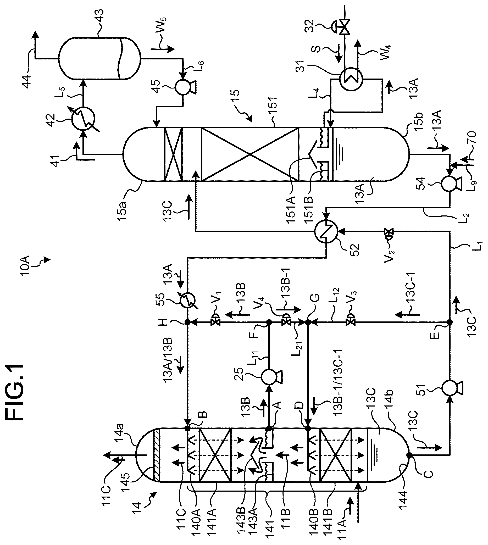
is a schematic view representing a configuration of a CO 2 recovery unit according to a first embodiment.
is a schematic view representing a configuration of a CO 2 recovery unit according to a second embodiment.
is a schematic view representing a configuration of a CO 2 recovery unit according to a third embodiment.
is a graph representing CO 2 concentration ratios in a rich solution in test example 1.
is a graph representing CO 2 recovery amount ratios in test example 1.
is a graph representing reduction percentages (%) of reboiler heat duty in an absorbent regenerator in test example 1.
is a graph representing CO 2 concentration ratios in a rich solution in test example 2.
is a graph representing CO 2 recovery amount ratios in test example 2.
is a graph representing reduction percentages (%) of reboiler heat duty in an absorbent regenerator in test example 2.
is a graph representing CO 2 concentration ratios in a rich solution in test example 3.
is a graph representing CO 2 recovery amount ratios in test example 3.
is a graph representing reduction percentages (%) of reboiler heat duty in an absorbent regenerator in test example 3.
is a graph representing CO 2 concentration ratios in a rich solution in test example 4.
is a graph representing CO 2 recovery amount ratios in test example 4.
is a graph representing reduction percentages (%) of reboiler heat duty in an absorbent regenerator in test example 4.
DESCRIPTION OF EMBODIMENTS
Hereinafter, preferred embodiments of the present invention are described in detail with reference to the accompanying drawings. The present invention is not limited to these embodiments, and modifications, additions, and omissions can be made by a person skilled in the art without departing from the spirit and scope stated in the claims.
First Embodiment
is a schematic view representing a configuration of a CO 2 recovery unit according to a first embodiment. As illustrated in , a CO 2 recovery unit 10 A is a unit for recovering CO 2 in an introduced gas (e.g., air) 11 A under nearly atmospheric pressure with a low concentration of CO 2 , for example. The CO 2 recovery unit 10 A is provided with: a CO 2 absorber 14 configured to bring the introduced gas 11 A into countercurrent contact with a lean solution 13 A of a CO 2 absorbent for allowing CO 2 contained in the introduced gas 11 A to be absorbed in the CO 2 absorbent and then removed; and an absorbent regenerator 15 that is formed at a subsequent stage of the CO 2 absorber 14 to release CO 2 from a rich solution 13 C of CO 2 absorbent containing absorbed CO 2 and then regenerate the lean solution 13 A.
In this CO 2 recovery unit 10 A, the CO 2 absorbent is circulated between the CO 2 absorber 14 and the absorbent regenerator 15 . The lean solution 13 A of the CO 2 absorbent obtained as a result of releasing CO 2 absorbs CO 2 from the gas in the CO 2 absorber 14 to become the rich solution 13 C. This rich solution 13 C is supplied to the absorbent regenerator 15 . The supplied rich solution 13 C release CO 2 in the absorbent regenerator 15 , and is regenerated as the lean solution 13 A to be subsequently supplied to the CO 2 absorber 14 . Here, the CO 2 absorbent is a generic term referring to: the lean solution 13 A obtained by releasing CO 2 ; a semi-rich solution 13 B that absorbs a part of CO 2 in the gas; and the rich solution 13 C that contains CO 2 absorbed from the gas and is discharged from the CO 2 absorber 14 . Each of the names is selected depending on circulating positions in the CO 2 recovery unit 10 A and the CO 2 content ratio.
The CO 2 absorbent usable in the present invention is not particularly limited. Examples of the CO 2 absorbent include amine compounds such as alkanolamines and hindered amines with alcoholic hydroxyl groups. Examples of such alkanolamines include monoethanolamine, diethanolamine, triethanolamine, methyl diethanolamine, diisopropanolamine, and diglycolamine. Among them, monoethanolamine (MEA) is generally preferred. Examples of such hindered amines with alcoholic hydroxyl groups include 2-amino-2-methyl-1-propanol (AMP), 2-(ethylamino)-ethanol (EAE), 2-(methylamino)-ethanol (MAE), and 2-(diethylamino)-ethanol (DEAE).
A rich solution supply line L 1 is provided to supply the rich solution 13 C containing CO 2 absorbed in the CO 2 absorber 14 to an upper side of the absorbent regenerator 15 between a bottom 14 b of the CO 2 absorber 14 and a top 15 a of the absorbent regenerator 15 . The rich solution supply line L 1 is provided with: a rich solution pump 51 configured to supply the rich solution 13 C containing CO 2 absorbed in the CO 2 absorber 14 to the absorbent regenerator 15 ; and a rich/lean solution heat exchanger 52 configured to heat the rich solution 13 C using the lean solution 13 A that is obtained as a result of releasing CO 2 by heating in the absorbent regenerator 15 .
A CO 2 absorption section 141 includes: a first CO 2 absorption stage 141 A (referred to as “first absorption stage”, hereinafter) arranged to absorb CO 2 from the introduced gas 11 A; and a second CO 2 absorption stage 141 B (referred to as “second absorption stage”, hereinafter) located below the first absorption stage 141 A that are disposed inside the CO 2 absorber 14 in its height direction.
A solution reservoir 143 A and a chimney tray 143 B are provided between the first absorption stage 141 A and the second absorption stage 141 B. The solution reservoir 143 A is arranged to store the semi-rich solution 13 B that is flowed down from upper portions of the first absorption stage 141 A to reach lower portions of the first absorption stage 141 A.
The solution reservoir 143 A is provided with a first absorbent circulation line L 11 that is arranged to discharge a whole amount of the semi-rich solution 13 B stored in the solution reservoir 143 A through a discharge position A of the CO 2 absorber 14 and introduce the discharged solution into an introduction position B located at the upper portion of the first absorption stage 141 A that is the same stage as that for the discharge.
The first absorbent circulation line L 11 is provided with a semi-rich solution pump 25 to circulate the semi-rich solution 13 B into the upper portion of the first absorption stage 141 A. The first absorbent circulation line L 11 is provided with a circulation flow control valve V 1 that controls a circulation flow rate of the circulated semi-rich solution 13 B.
A front end of a lean solution supply line L 2 is connected to the first absorbent circulation line L 11 at a connection position H, such that the lean solution 13 A regenerated in the absorbent regenerator 15 is mixed with the circulated semi-rich solution 13 B (circulation solution 13 B) to form a mixture ( 13 A/ 13 B). The mixture is introduced into an upper stage liquid distributor 140 A. The front end of the lean solution supply line L 2 may be connected directly to the upper stage liquid distributor 140 A at the upper portion of the first absorption stage 141 A without connected to the first absorbent circulation line L 11 such that the lean solution 13 A and the circulated semi-rich solution 13 B (circulation solution 13 B) are individually introduced into the upper stage liquid distributor 140 A.
A second absorbent circulation line L 12 is provided to be connected at a liquid reservoir 144 located at a bottom of the CO 2 absorber to discharge a whole amount of the rich solution 13 C stored in the liquid reservoir 144 through a discharge position C of the CO 2 absorber 14 and introduce the discharged solution into an introduction position D positioned at an upper part of the second absorption stage 141 B that is the same stage as the stage for the discharge.
A part of the rich solution 13 C is separated as a circulation solution 13 C- 1 at a discharge position E by the second absorbent circulation line L 12 . The second absorbent circulation line L 12 is connected at the discharge position E to a base end of the rich solution supply line L 1 . The rich solution 13 C discharged is supplied through the rich solution supply line L 1 to the absorbent regenerator 15 . The rich solution supply line L 1 is provided with a rich solution flow control valve V 2 to control the amount of the rich solution 13 C supplied to the absorbent regenerator 15 . The second absorbent circulation line L 12 is provided with a circulation flow control valve V 3 to control the circulation flow rate of the circulated circulation solution 13 C- 1 .
An absorbent discharge line L 21 is provided to discharge a part of the semi-rich solution 13 B (circulation solution 13 B) circulated from the first absorbent circulation line L 11 as a discharged solution 13 B- 1 at a discharge position F and supply the discharged solution 13 B- 1 to the second absorption stage 141 B that is the adjacent stage immediately below the stage for the discharge.
In the present embodiment, the front end of the absorbent discharge line L 21 is connected at a connection position G to the second absorbent circulation line L 12 , such that the discharged solution 13 B- 1 is mixed with the circulation solution 13 C- 1 to form the mixture ( 13 B- 1 / 13 C- 1 ). The mixture is supplied through a single line to the introduction position D located at the upper portion of the second absorption stage 141 B. The front end of the absorbent discharge line L 21 may be connected directly to the lower stage liquid distributor 140 B at the upper portion of the second absorption stage 141 B without connected to the second absorbent circulation line L 12 such that the discharged solution 13 B- 1 and the circulation solution 13 C- 1 are individually introduced into the lower stage liquid distributor 140 B.
In addition, a discharge flow control valve V 4 is provided in the absorbent discharge line L 21 to control the discharge flow rate of the discharged solution 13 B- 1 .
In the first absorption stage 141 A, the lean solution 13 A regenerated in the absorbent regenerator 15 and the circulated semi-rich solution 13 B (circulation liquid 13 B) are supplied as the CO 2 absorbents. The supplied lean solution 13 A and the circulated semi-rich solution 13 B (circulation liquid 13 B) are distributed from the upper stage liquid distributor 140 A that is located at the upper portion of the first absorption stage 141 A, and then flowed down within a packed bed. Here, the semi-rich solution 13 B as the circulation solution has a higher CO 2 concentration than the lean solution 13 A, but is still capable of absorbing CO 2 . Thus, the semi-rich solution 13 B can be reused in the first absorption stage 141 A to absorb CO 2 from the introduced gas 11 B.
To the second absorption stage 141 B, the circulation solution 13 C- 1 is supplied together with the discharged solution 13 B- 1 of the semi-rich solution 13 B containing CO 2 absorbed partially from the introduced gas 11 B in the first absorption stage 141 A. The supplied discharged solution 13 B- 1 and the circulation solution 13 C- 1 are distributed from the lower stage liquid distributor 140 B at the upper portions of the second absorption stage 141 B and flowed down within the packed bed. Here, the rich solution 13 C as the circulation solution has a higher CO 2 concentration than the semi-rich solution 13 B, but is still capable of absorbing CO 2 . Thus, the rich solution 13 C can be reused in the second absorption stage 141 B to absorb CO 2 from the introduced gas 11 A.
In the first absorption stage 141 A of the CO 2 absorber 14 , the introduced gas 11 B containing CO 2 is brought into countercurrent contact with the mixture of the lean solution 13 A made of the amine compound-based CO 2 absorbent and the circulated semi-rich solution 13 B (circulation solution 13 B) that are introduced into the tower. As a result, the gas introduced into the tower becomes an outlet gas 11 C by removing CO 2 in the gas while the lean solution 13 A becomes the semi-rich solution 13 B.
In the second absorption stage 141 B, the semi-rich solution 13 B (discharged solution 13 B- 1 and the circulation solution 13 C- 1 ) partially absorbing CO 2 is brought into countercurrent contact with the introduced gas 11 A that contains CO 2 and is introduced from a bottom side of the tower, allowing CO 2 to be absorbed into the semi-rich solution 13 B from the introduced gas 11 A by a chemical reaction. As a result, the introduced gas 11 A becomes the introduced gas 11 B with a reduced CO 2 concentration by removing CO 2 in the gas while the semi-rich solution 13 B becomes the rich solution 13 C with higher amount of absorbed CO 2 . This arrangement allows the introduced gases 11 A and 11 B containing CO 2 to be flowed through the first absorption stage 141 A and the second absorption stage 141 B, removing CO 2 to provide a decarbonated outlet gas 11 C.
A mist eliminator 145 is installed inside a tower top 14 a to capture mist contained in the decarbonated outlet gas 11 C and then discharge the gas outwardly from the tower top 14 a of the CO 2 absorber 14 .
The absorbent regenerator 15 is provided at its interior with a packed bed 151 to release CO 2 with aid of water vapor from the rich solution 13 C containing absorbed CO 2 . The absorbent regenerator 15 is provided at the vicinity of a tower bottom 15 b with a circulation line L 4 that circulates therethrough a part of the lean solution 13 A flowed down to the tower bottom 15 b . The circulation line L 4 is provided with a reboiler 31 that generates water vapor by indirect heating of the lean solution 13 A with use of saturated steam S, and a control valve 32 that controls the amount of saturated steam S supplied to the reboiler 31 . The saturated steam S becomes steam condensate W 4 after the heating.
The absorbent regenerator 15 is provided at its top 15 a with a gas discharge line L 5 to discharge CO 2 gas 41 together with water vapor. The gas discharge line L 5 is provided with a condenser 42 that condenses the water vapor discharged together with the CO 2 gas 41 into water, and a separation drum 43 to separate a CO 2 gas 44 from condensed water W 5 . The CO 2 gas 44 separated from the condensed water W 5 is discharged outwardly from an upper portion of the separation drum 43 . A condensed water line L 6 is provided between the bottom part of the separation drum 43 and the top 15 a of the absorbent regenerator 15 to supply the condensed water W 5 separated in the separation drum 43 to the top 15 a of the absorbent regenerator 15 . The condensed water line L 6 is provided with a condensed water circulation pump 45 to supply the condensed water W 5 separated in the separation drum 43 to the top 15 a of the absorbent regenerator 15 .
The lean solution supply line L 2 is provided between the bottom 15 b of the absorbent regenerator 15 and the top 14 a of the CO 2 absorber 14 to supply the lean solution 13 A of the CO 2 absorbent from the bottom 15 b of the absorbent regenerator 15 to the upper side of the CO 2 absorption section 141 . The lean solution supply line L 2 is provided with: a rich/lean solution heat exchanger 52 that heats the rich solution 13 C containing the absorbed CO 2 with use of the lean solution 13 A that is obtained by heating with water vapor in the absorbent regenerator 15 for the removal of CO 2 ; a lean solution pump 54 that supplies the lean solution 13 A from the bottom 15 b of the absorbent regenerator 15 to the upper portion of the CO 2 absorption section 141 ; and a cooling part 55 that cools the lean solution 13 A of the CO 2 absorbent down to a predetermined temperature.
In the present embodiment, this cooling part 55 is configured to cool the lean solution 13 A down to the same temperature as or a temperature close to a gas temperature (room temperature: e.g., 25° C.) of the introduced gas 11 A introduced into the CO 2 absorber 14 .
Next, the overall operation of the CO 2 recovery unit 10 A according to the present embodiment is described. For example, the introduced gas (atmospheric gas) 11 A containing a subtle amount of CO 2 is introduced into the interior of the CO 2 absorber 14 through the bottom 14 b of the CO 2 absorber 14 and flows upward inside the tower. The gas introduced into the CO 2 absorber 14 is brought into countercurrent contact with the CO 2 absorbent containing the amine compound such as alkanolamine in the first absorption stage 141 A and second absorption stage 141 B of the CO 2 absorption section 141 , such that CO 2 is absorbed from the gas into the CO 2 absorbent and then removed for the purpose of providing the decarbonated outlet gas 11 C.
The decarbonated outlet gas 11 C is discharged outwardly from the top 14 a of the CO 2 absorber 14 .
After the absorption of CO 2 in the CO 2 absorber 14 , the rich solution 13 C of the CO 2 absorbent is flowed in the rich solution supply line L 1 to pass through the rich/lean solution heat exchanger 52 for heat exchange with the lean solution 13 A and then supplied to the top side of the absorbent regenerator 15 with the aid of the rich solution pump 51 .
The rich solution 13 C of the CO 2 absorbent supplied to the absorbent regenerator 15 is allowed to release CO 2 by the heat of the water vapor supplied from the reboiler 31 while flowing downward inside the packed bed 151 of the absorbent regenerator 15 , so as to become the lean solution 13 A. In the absorbent regenerator 15 , the solution is circulated from the liquid reservoirs 151 B of the chimney tray 151 A into the circulation line L 4 while heated by saturated steam S in the reboiler 31 to generate water vapor inside the absorbent regenerator 15 . The lean solution 13 A is obtained as a result of releasing CO 2 from the rich solution 13 C with the aid of the heat of this generated water vapor. After the heating, the saturated steam S becomes steam condensate W 4 . The CO 2 gas 41 released together with the water vapor from the CO 2 absorbent is cooled down for the condensation into water with use of the condenser 42 , separated from the condensed water W 5 , and then discharged as the CO 2 gas 44 outwardly through the upper portion of the separation drum 43 . The condensed water W 5 separated is supplied to the absorbent regenerator 15 .
After discharged from the bottom 15 b of the absorbent regenerator 15 , the lean solution 13 A is flowed in the lean solution supply line L 2 to pass through the rich/lean solution heat exchanger 52 for heat exchange with the rich solution 13 C and then supplied to the upper side of the CO 2 absorption section 141 of the CO 2 absorber 14 with the aid of the lean solution pump 54 .
After supplied to the upper side of the CO 2 absorption section 141 , the lean solution 13 A absorbs CO 2 from the introduced gas 11 B in the first absorption stage 141 A to become the semi-rich solution 13 B, which is discharged at the discharge position A at the lower portion of the first absorption stage 141 A and flowed into the first absorbent circulation line L 11 . The discharged semi-rich solution 13 B is supplied with the aid of the semi-rich solution pump 25 together with the lean solution 13 A to the introduction position B positioned at the upper side of the first absorption stage 141 A.
In the second absorption stage 141 B, CO 2 is absorbed from the introduced gas 11 B to form the rich solution 13 C. The rich solution 13 C is discharged at the discharge position C at the lower part of the second absorption stage 141 B and flowed into the second absorbent circulation line L 12 . The discharged rich solution 13 C is separated at the discharge position E, as the circulation solution 13 C- 1 . Then, the circulation solution 13 C- 1 is supplied with the aid of the rich solution pump 51 to the introduction position D at the upper portion of the second absorption stage 141 B.
A part of the semi-rich solution 13 B is separated at the discharge position F of the first absorbent circulation line L 11 by the absorbent discharge line L 21 . The discharged solution 13 B- 1 is mixed with the circulation solution 13 C- 1 at the connection position G of the second absorbent circulation line L 12 . This discharged solution 13 B- 1 and the circulation solution 13 C- 1 are mixed with each other ( 13 B- 1 / 13 C- 1 ) and then supplied through a single line to the introduction position D at the upper portion of the second absorption stage 141 B.
After separated from the circulation solution 13 C- 1 at the discharge position E, the rich solution 13 C is supplied to the absorbent regenerator 15 through the rich solution supply line L 1 .
Therefore, the configuration according to the present embodiment includes: the first absorbent circulation line L 11 for supplying the semi-rich solution 13 B discharged at the lower side of the first absorption stage 141 A in the CO 2 absorber 14 to the upper side of the same stage 141 A as the stage for the discharge; the second absorbent circulation line L 12 for supplying the rich solution 13 C discharged at the lower side of the second absorption stage 141 B of the CO 2 absorber 14 to the upper side of the second absorption stage 141 B that is the same stage as the stage for the discharge; the absorbent discharge line L 21 for separating the circulated semi-rich solution 13 B (circulation solution 13 B) discharged at the lower side of the first absorption stage 141 A and then mixing the separated solution with the lean solution 13 C- 1 that is discharged at the lower side of the second absorption stage 141 B that is the adjacent stage immediately below the stage for the discharge; the lean solution supply line L 2 for supplying the lean solution from the absorbent regenerator 15 to the upper portion of the first absorption stage 141 A that is the highest stage of the CO 2 absorber 14 and then mixing the supplied solution with the semi-rich solution 13 B discharged at the lower side of the first absorption stage 141 A; and the rich solution supply line L 1 for flowing the rich solution 13 C from the bottom part of the CO 2 absorber 14 to the absorbent regenerator 15 .
Thus, according to the first embodiment, after absorbing CO 2 , the semi-rich solution 13 B and the rich solution 13 C that contain absorbed CO 2 can be discharged and flowed outwardly through the lower sides of the first absorption stage 141 A and the second absorption stage 14 B, respectively, and supplied as the circulation solutions to the upper portions at the corresponding stages above the absorbent-discharged portions. This allows the circulated circulation solutions to be reused as the absorbents in the first absorption stage 141 A and the second absorption stage 14 B to recover CO 2 in the gas. As a result, with increase of the CO 2 concentration in the CO 2 absorbent, it is possible to improve the CO 2 recovery efficiency in the CO 2 absorber 14 and thereby increase the CO 2 recovery amount per unit volume of the CO 2 absorbent. Furthermore, the CO 2 concentration in the rich solution 13 C can be increased at the bottom 14 b of the CO 2 absorber 14 , thereby allowing the rich solution 13 C having an increased CO 2 concentration to be supplied to the absorbent regenerator 15 .
Here, when the two-stage configuration for the absorption section, the first absorption stage 141 A and the second absorption stage 141 B, as in the present embodiment, the solution discharged from the circulation solution 13 C- 1 is the rich solution 13 C, while the rich solution supply line L 1 functions as an absorbent discharge line to supply the discharged rich solution 13 C to the absorbent regenerator 15 . In the case of three-stage configuration for the absorption section, the first absorption stage 141 A, the second absorption stage 141 B, and a third absorption stage, a solution discharged from the circulation solution 13 C- 1 , which is supplied from the second absorption stage 141 B, is supplied as the discharged solution to the third absorption stage immediately below the discharged stage of the second absorption stage.
As a result, the semi-rich solution 13 B and the rich solution 13 C are reused twice in the CO 2 absorber 14 , enabling it to reduce the flow rate of the circulated CO 2 absorbent in the system circulating between the CO 2 absorber 14 and the absorbent regenerator 15 . This can reduce the flow rate of the rich solution 13 C supplied to the absorbent regenerator 15 , reducing the steam supply amount of the reboiler 31 used in the absorbent regenerator 15 for the regeneration of the CO 2 absorbent, and thereby reducing heat energy consumption to improve energy efficiency.
In the present embodiment, even in the case of recovering CO 2 from a gas containing a very subtle amount of CO 2 (e.g., air), the CO 2 concentration can be increased in the rich solution 13 C supplied to the absorbent regenerator 15 so as to reduce the steam amount required in the absorbent regenerator 15 , thereby reducing the thermal energy as well as achieving further energy saving in the process of regenerating the CO 2 absorbent.
Next, the separation ratios of the circulation solution to the discharged solution in the CO 2 recovery unit 10 A according to the present embodiment, is described.
In the present embodiment, regarding the flow rate (f1) of the semi-rich solution 13 B (circulation solution 13 B) circulated through the first absorbent circulation line L 11 from the lower portion of the first absorption stage 141 A and the flow rate (f2) of the discharged solution 13 B- 1 discharged via the absorbent discharge line L 21 , the separation ratio of the flow rates (referred to as “separation flow ratio”, hereinafter) is preferably 1:1 to 60:1, preferably 10:1 to 60:1, more preferably 30:1 to 60:1.
Regarding the flow rate (f3) of the circulation solution 13 C- 1 flowed into the second absorbent circulation line L 12 and the flow rate (f4) of the rich solution 13 C flowed into the rich solution supply line L 1 from the bottom of the CO 2 absorber 14 , the flow separation ratio of the flow rates is preferably 1:1 to 60:1, preferably 10:1 to 60:1, more preferably 30:1 to 60:1.
Hereinafter, preferred test examples exhibiting effects of the separation flow ratio according to the present embodiment are described. The present invention is not limited to these examples. to 9 in these test examples illustrate examples for gas having a CO 2 concentration of 1% or less.
a graph representing CO 2 concentration ratios in the rich solution in test example 1. Herein, represents a performance improvement ratio calculated based on standardized CO 2 concentration (1) without the discharge at each stage. In , the horizontal axis represents the separation flow ratio of the flow rate (f1) of the semi-rich solution 13 B (circulation solution 13 B) circulated through the first absorbent circulation line L 11 to the flow rate (f2) of the discharged solution 13 B- 1 supplied to the absorbent discharge line L 21 , in the range of 1:1 to 60:1 (the same applies to ). The same applies to the separation flow ratio of the flow rate (f1) of the circulation solution 13 C- 1 circulated through the second absorbent circulation line L 12 to the flow rate (f2) of the rich solution 13 C supplied to the rich solution supply line L 1 , in the range of 1:1 to 60:1.
is a graph representing CO 2 recovery amount ratios in test example 1. Herein, represents a performance improvement ratio calculated based on standardized CO 2 recovery amount (1) without the discharge at each stage. is a graph representing reduction percentages (%) of reboiler heat duty in the absorbent regenerator in test example 1. represents the reduction percentages (%) calculated based on standardized reboiler heat duty reduction percentages (0) without the discharge.
As illustrated in to 6 , in test example 1, the separation flow ratio in the range of 1:1 to 60:1 allows for improvement in the separation effects on the CO 2 concentration ratio in the rich solution, the CO 2 recovery amount ratio, and the reboiler heat duty reduction percentage (%). In particular, the separation flow ratio in the range of 1:1 to 40:1 allows for improvement in the increase ratio of the separation effects on the CO 2 concentration ratio in the rich solution, the CO 2 recovery amount ratio, and the reboiler heat duty reduction percentage (%).
Here, the CO 2 absorption rate of the absorbent is represented as the product of the volumetric mass transfer coefficient (the product of the mass transfer coefficient and the gas-liquid contact area) and the driving force (the difference between the CO 2 partial pressure and the CO 2 equilibrium pressure). In the case of returning the absorbent of the semi-rich solution 13 B (circulation solution 13 B) circulating from the rich solution side at the bottom side of the CO 2 absorber 14 to the top of the CO 2 absorber 14 , as disclosed in the prior art (Patent Literature 1), the concentration of acid gas (CO 2 ) may be increased at the outlet side due to decrease in the driving force when the CO 2 content is high in the gas (such as boiler flue gas with a CO 2 concentration of more than 10% and 15% or less).
In contrast, when CO 2 is removed from the gas with a low CO 2 concentration of 1% such as atmospheric air as in this test example, even if the absorbent is circulated from the rich solution side on the bottom side of the CO 2 absorber to the lean solution side on the upper side of the CO 2 absorber including the top thereof, it is possible to improve the volumetric mass transfer coefficient to such a great extent as to outweigh the decrease of the driving force, and thereby improve the CO 2 absorption rate. Thus, the improvement in CO 2 absorption rate in the present invention is particularly noticeable under conditions with the relatively low CO 2 concentration in the target gas.
Therefore, examples of the gas with low CO 2 concentration applicable to the present invention include a gas at nearly atmospheric pressure containing a subtle amount (with a CO 2 concentration of 1% or less), preferably a gas at nearly atmospheric pressure with a CO 2 concentration of 10% or less, more preferably a gas at nearly atmospheric pressure with a CO 2 concentration of 5% or less. Examples of the gas with a CO 2 concentration of 10% or less include flue gases from boilers, gas turbines, combustion furnaces, heating furnaces, incinerators, internal combustion engines, and the like, for example, as well as atmospheric air and air in closed and substantially closed spaces.
In the present invention, in the case of targeting air, or air in the closed or substantially closed space, the lean absorbent temperature is desired to be same as or as close as possible to the target gas temperature.
When the introduced gas 11 in the CO 2 absorber 14 is atmospheric gas or air with unsaturated water vapor, the water content of the absorbent is evaporated and then exhausted as moisture saturated gas, thereby requiring water to be supplied to the absorbent. The higher the lean solution temperature, the higher amount of water supplied to the absorbent, due to increase in the temperature of the outlet gas 11 C of the CO 2 absorber 14 and increased amount of exhausted water content resulting from increase of saturated water content. For this reason, as illustrated in , the lean solution supply line L 2 is provided with a supply water introduction line L 9 to introduce supplied water 70 to dilute the absorbent in the present embodiment, preventing the amine concentration from increased in the absorbent.
The amount of absorbed CO 2 is small when the introduced gas 11 A in the CO 2 absorber 14 is atmospheric gas or air with unsaturated water vapor. Thus, the amount of heat absorption resulting from the evaporative latent heat of water content is greater than the amount of heat generated by the reaction when CO 2 is absorbed from the flue gas exhausted from the boiler as in the conventional system. Therefore, even when the lean solution 13 A with the same temperature as the introduced gas 11 A is used, for example, the outlet gas temperature (T 2 ) of the outlet gas 11 C is lower by approximately 3° C. than that (T 1 ) of the introduced gas 11 A under the condition that the gas temperature (T 1 ) of the introduced gas 11 A in test example 1 according to first embodiment is 25° C.
Thus, under the condition that CO 2 is removed from a gas containing a subtle amount of CO 2 (a CO 2 concentration of 1% or less), the temperature of the circulation solution in the absorption section is lower than that of the lean solution 13 A introduced into the CO 2 absorber 14 , without a cooler installed in the first absorbent circulation line L 11 and the second absorbent circulation line L 12 . As a result, the reaction heat of the amine solution is not generated when CO 2 is absorbed inside the absorber as in the prior arts, thereby not requiring the cooler in the first absorbent circulation line L 11 and the second absorbent circulation line L 12 in which the semi-rich solution 13 B and the rich solution 13 C are circulated.
to 9 illustrate performances with comparison to the prior art (Patent Literature 2: International Publication No. 09/104744) in which only the second absorbent circulation line L 12 is used to circulate the absorbent, without the first absorbent circulation line L 11 installed as in the present invention, (with circulation at the lower stage without circulation at the upper stage) (Comparative Example 2).
is a graph representing CO 2 concentration ratios in the rich solution in test example 2. Herein, represents a performance improvement ratio calculated based on standardized CO 2 concentration (1) with circulation at the lower stage without circulation at the upper stage. In , the horizontal axis represents the separation flow ratio of the flow rate (f1) of the semi-rich solution 13 B (circulation solution 13 B) circulated through the first absorbent circulation line L 11 to the flow rate (f2) of the discharged solution 13 B- 1 supplied to the absorbent discharge line L 21 , in the range of 1:1 to 60:1 (the same applies to ). The same applies to the separation flow ratio of the flow rate (f1) of the circulation solution 13 C- 1 circulated through the second absorbent circulation line L 12 to the flow rate (f2) of the rich solution 13 C supplied to the rich solution supply line L 1 , in the range of 1:1 to 60:1.
is a graph representing CO 2 recovery amount ratios in test example 2. Herein, represents the performance improvement ratio calculated based on standardized CO 2 recovery amount (1) with circulation at the lower stage without circulation at the upper stage.
is a graph representing reduction percentages (%) of reboiler heat duty in the absorbent regenerator in test example 2. represents the reduction percentages (%) calculated based on standardized reboiler heat duty reduction percentages (0) with circulation at the lower stage without circulation at the upper stage.
As illustrated in to 9 , in test example 2, the separation ratio of the flow rates in the range of 1:1 to 60:1 allows for improvement in the separation effects on the CO 2 concentration ratio in the rich solution, the CO 2 recovery amount ratio, and the reboiler heat duty reduction percentage (%). In particular, the separation ratio of the flow rates in the range of 1:1 to 30:1 allows for improvement in the increase ratio of the separation effects on the CO 2 concentration ratio in the rich solution, the CO 2 recovery amount ratio, and the reboiler heat duty reduction percentage (%).
Although explanations are given for the CO 2 recovery unit 10 A according to the present embodiment in which two absorption stages (the first absorption stage 141 A and the second absorption stage 141 B) are provided in the CO 2 absorber 14 , the present invention is not limited to this. Two or more absorption stages are provided (another absorption stage is provided between the first absorption stage 141 A and the second absorption stage 141 B) in the CO 2 absorber 14 such that the circulation and discharge are performed at the predetermined separation ratio of the flow rates to circulate the absorbent.
Second Embodiment
is a schematic view representing configuration of a CO 2 recovery unit according to a second embodiment. Descriptions are given for new configuration in the second embodiment added to the CO 2 recovery unit 10 A according to the first embodiment illustrated in . The same components as in the configuration according to the first embodiment are not described.
A CO 2 recovery unit 10 B according to the second embodiment is provided with a wash section 142 that is added inside the top part 14 a of the first absorption stage 141 A of the CO 2 absorber 14 on a downstream side of the gas flow in the CO 2 recovery unit 10 A according to the first embodiment.
The wash section 142 is provided at its bottom with a liquid reservoir 144 A that stores therein washing water W 2 to wash the decarbonated outlet gas 11 C. A circulation line L 3 is provided between the liquid reservoir 144 A and the top of the wash section 142 to supply wash water W 2 containing the CO 2 absorbent collected in the liquid reservoir 144 A for circulation from the top part 14 a side of the wash section 142 . The circulation line L 3 is equipped with a heat exchanger 21 that cools the wash water W 2 and a circulation pump 22 that circulates the wash water W 2 containing the CO 2 absorbent collected in the liquid reservoir 144 A through the heat exchanger 21 in the circulation line L 3 .
In the present embodiment, CO 2 is recovered in the gas with low CO 2 concentration, thereby the CO 2 absorption does not involve the exothermic reaction of the amine-based absorbent, as described above. However, the water wash section 142 illustrated in is preferably provided to minimize loss of the amine-based absorbent in the outlet gas 11 C discharged outwardly, from the perspective of achieving near zero emission.
Third Embodiment
is a schematic view representing configuration of a CO 2 recovery unit according to a third embodiment. Descriptions are given for new configuration in the third embodiment added to the CO 2 recovery unit 10 B according to the second embodiment illustrated in . The same components as in the configuration according to the first embodiment are not described.
A CO 2 recovery unit 10 C according to the third embodiment is provided with a gas quencher 12 , which is added on an upstream side of the CO 2 absorber 14 in the CO 2 recovery unit 10 B according to the second embodiment, to cool the introduced gas 11 A down to a predetermined temperature. The gas quencher 12 has a quencher section 121 to cool the introduced gas 11 A. A water circulation line L 7 is provided to circulate the cooling water W 1 between the bottom 12 b side of the gas quencher 12 and the top 12 a side of the quencher section 121 . The water circulation line L 7 is equipped with a heat exchanger 122 that cools the cooling water W 1 and a circulation pump 123 that circulates the cooling water W 1 in the water circulation line L 7 .
In the quencher section 121 , the introduced gas 11 A is brought into countercurrent contact with the cooling water W 1 so as to be cooled down to a predetermined temperature. The heat exchanger 122 cools the cooling water W 1 heated by heat exchange with the introduced gas 11 A. The circulation pump 123 supplies the cooling water W 1 flowing down to the bottom 12 b of the gas quencher 12 via the heat exchanger 122 to the top 12 a of the quencher section 121 . After cooled, the introduced gas 11 A is introduced into the CO 2 absorber 14 from the vicinity of the bottom of the CO 2 absorber 14 via the introduction line L 8 .
In the third embodiment, the cooling part 55 , which is installed in the lean solution supply line L 2 in the preceding configuration, is installed in the first absorbent circulation line L 11 . This allows for cooling of the mixed solution ( 13 A/ 13 B) of the semi-rich solution 13 B (circulation solution 13 B) circulating from the first absorbent circulation line L 11 and the lean solution 13 A flowed from the lean solution supply line L 2 .
The present embodiment differs from the first embodiment in that it is preferable to aim for gases (e.g., turbine flue gas and various flue gases) containing 3% or more and 10% or less of CO 2 as the introduced gas 11 A. For the gases containing 3% or more of CO 2 , the liquid temperature of the lean solution 13 A is expected to be a lean absorbent temperature at a temperature level of the water vapor-saturated gas flowed at the outlet of the gas quencher 12 .
For example, under the condition that the gas temperature of the introduced gas 11 A in the present embodiment is 40° C., when the absorbent is not circulated at each stage as in the prior art, the gas temperature of the outlet gas 11 C discharged from the top 14 a is approximately 10° C. higher than the gas temperature of the introduced gas. Therefore, under such a condition, it is more advantageous to install the cooling part 55 in the first absorbent circulation line L 11 to prevent the temperature of the absorbent from rising, for increasing the CO 2 concentration in the absorbent.
Hereinafter, preferred test examples exhibiting effects of the separation flow ratio according to the present embodiment are described. The present invention is not limited to these examples. to 15 of the test examples illustrate examples aimed for gases with a CO 2 concentration of 3% or more.
a graph representing CO 2 concentration ratios in the rich solution in test example 3. Herein, represents a performance improvement ratio calculated based on standardized CO 2 concentration (1) without the discharge at each stage. In , the horizontal axis represents the separation flow ratio of the flow rate (f1) of the semi-rich solution 13 B (circulation solution 13 B) circulated through the first absorbent circulation line L 11 to the flow rate (f2) of the discharged solution 13 B- 1 supplied to the absorbent discharge line L 21 , in the range of 1:1 to 60:1 (the same applies to ). The same applies to the separation flow ratio of the flow rate (f1) of the circulation solution 13 C- 1 circulated through the second absorbent circulation line L 12 to the flow rate (f2) of the rich solution 13 C supplied to the rich solution supply line L 1 , in the range of 1:1 to 60:1.
is a graph representing CO 2 recovery amount ratios in test example 3. Herein, represents a performance improvement ratio calculated based on standardized CO 2 recovery amount (1) without the discharge at each stage. is a graph representing reduction percentages (%) of reboiler heat duty in the absorbent regenerator in test example 3. represents the reduction percentages (%) calculated based on standardized reboiler heat duty reduction percentages (0) without the discharge.
As illustrated in to 12 , in test example 3, the separation flow ratio in the range of 1:1 to 60:1 allows for increase of the separation effects on the CO 2 concentration ratio in the rich solution, the CO 2 recovery amount ratio, and the reboiler heat duty reduction percentage (%). In particular, the separation flow ratio in the range of 1:1 to 20:1 allows for improvement in the increase ratio of the separation effects on the CO 2 concentration ratio in the rich solution, the CO 2 recovery amount ratio, and the reboiler heat duty reduction percentage (%).
to 15 illustrate performances with comparison to the prior art (Patent Literature 2: International Publication No. 09/104744) in which only the second absorbent circulation line L 12 is used to circulate the absorbent, without the first absorbent circulation line L 11 installed as in the present invention, (with circulation at the lower stage without circulation at the upper stage) (Comparative Example 2).
is a graph representing CO 2 concentration ratios in the rich solution in test example 4. Herein, represents a performance improvement ratio calculated based on standardized CO 2 concentration (1) with circulation at the lower stage without circulation at the upper stage. In , the horizontal axis represents the separation flow ratio of the flow rate (f1) of the semi-rich solution 13 B (circulation solution 13 B) circulated through the first absorbent circulation line L 11 to the flow rate (f2) of the discharged solution 13 B- 1 supplied to the absorbent discharge line L 21 , in the range of 1:1 to 60:1 (the same applies to ). The same applies to the separation flow ratio of the flow rate (f1) of the circulation solution 13 C- 1 circulated through the second absorbent circulation line L 12 to the flow rate (f2) of the rich solution 13 C supplied to the rich solution supply line L 1 , in the range of 1:1 to 60:1.
is a graph representing CO 2 recovery amount ratios in test example 4. Herein, represents the performance improvement ratio calculated based on standardized CO 2 recovery amount (1) with circulation at the lower stage without circulation at the upper stage. is a graph representing reduction percentages (%) of reboiler heat duty in the absorbent regenerator in test example 4. represents the reduction percentages (%) calculated based on standardized the reboiler heat duty reduction percentages (0) with circulation at the lower stage without circulation at the upper stage.
As illustrated in to 15 , in test example 4, the separation ratio of the flow rates in the range of 1:1 to 60:1 allows for improvement of the separation effects on the CO 2 concentration ratio in the rich solution, the CO 2 recovery amount ratio, and the reboiler heat duty reduction percentage (%). In particular, the separation ratio of the flow rates in the range of 1:1 to 40:1 allows for improvement in the increase ratio of the separation effects on the CO 2 concentration ratio in the rich solution, the CO 2 recovery amount ratio, and the reboiler heat duty reduction percentage (%).
The CO 2 recovery unit and the CO 2 recovery method described in the embodiments are understood, for example, as follows.
The CO 2 recovery unit 10 A, 10 B, 10 C according to a first aspect includes: the CO 2 absorber 14 configured to bring the introduced gas 11 A having a low CO 2 concentration into countercurrent contact with the CO 2 absorbent and remove CO 2 ; the absorbent regenerator 15 configured for heat exchange between the rich solution 13 C containing absorbed CO 2 and the vapor flowed from the reboiler 31 to regenerate the CO 2 absorbent; the rich solution supply line L 1 configured to discharge the rich solution 13 C containing absorbed CO 2 from the bottom 14 b of the CO 2 absorber 14 and supply the rich solution to the top side of the absorbent regenerator 15 ; and the lean solution supply line L 2 configured to discharge the lean solution 13 A, which is obtained after releasing CO 2 , from the bottom 15 b of the absorbent regenerator 15 , and supply it to the top side of the CO 2 absorber 14 , in which the CO 2 absorber 14 has at least two or more CO 2 absorption stages 141 A, 141 B. The CO 2 recovery unit 10 A further includes: the absorbent circulation lines L 11 , L 12 configured to discharge the CO 2 absorbent from the lower sides of the CO 2 absorption stages 141 A, 141 B and supply the CO 2 absorbent as the circulating semi-rich solution 13 B (circulation solution 13 B) and the circulating rich solution 13 C (circulation solution 13 C- 1 ) to the upper sides of the corresponding CO 2 absorption stages 141 A, 141 B that are used as the discharge stages; and the absorbent discharge lines L 21 , L 1 configured to discharge parts of the semi-rich solution 13 B (circulation solution 13 B) circulation solution 13 C- 1 from the absorbent circulation lines L 11 , L 12 and supply the solution as the discharged solutions 13 B- 1 , 13 C to adjacent stage immediately below the discharge stages.
This configuration enables it to discharge the CO 2 absorbent containing the absorbed CO 2 from the lower portion of each of the CO 2 absorption stages, supply it to the upper portion of the corresponding stage at which the CO 2 absorbent is discharged, and reuse the solution as the CO 2 absorbent for the purpose of recovering CO 2 in the gas, increasing the CO 2 concentration in the CO 2 absorbent, and reducing the reboiler heat duty needed for recovering CO 2 from a variety of gases with low CO 2 contents.
The CO 2 recovery unit 10 A, 10 B, 10 C according to a second aspect is aimed for the introduced gas 11 A with a CO 2 concentration of 10% by volume or less.
This configuration enables it to reduce the reboiler heat duty needed for recovering CO 2 from the introduced gas 11 A with a CO 2 concentration of 10% by volume or less.
In the CO 2 recovery unit 10 A, 10 B, 10 C according to a third aspect, the flow ratio is set at 1:1 to 60:1 for the separation ratio of the flow rates of the circulation solution 13 B, 13 C- 1 to the discharged solution 13 B- 1 , 13 C.
With the separation ratio of the flow rates of the circulation solution 13 B, 13 C- 1 to the discharged solution 13 B- 1 , 13 C ranging from 1:1 to 60:1 in this configuration, it is possible to reduce the reboiler heat duty needed for recovering CO 2 from a variety of gases with low CO 2 contents.
The CO 2 recovery unit 10 B, 10 C according to a fourth aspect is provided with the wash section 142 at the downstream side of gas flow in the CO 2 absorption section at the highest stage.
This configuration having the wash section 142 enables it to wash the outlet gas 11 C with water, and thereby minimize the loss of the amine-based absorbent in the outlet gas 11 C released outwardly.
The CO 2 recovery unit 10 C according to a fifth aspect has the cooling part 55 in the first absorbent circulation line L 11 .
With the cooling part 55 in the first absorbent circulation line L 11 , this configuration enables it to prevent the temperature of the absorbent from increasing, achieving advantageous effects on the increase in the CO 2 concentration in the absorbent.
A CO 2 recovery method according to a sixth aspect includes: a CO 2 absorption step of bringing the introduced gas 11 A having low CO 2 concentration into countercurrent contact with the CO 2 absorbent to remove CO 2 ; an absorbent regeneration step of performing the heat exchange between the rich solution 13 C containing the absorbed CO 2 and the steam flowed from the reboiler 31 to regenerate the CO 2 absorbent; and a step of discharging the rich solution 13 C containing CO 2 that is absorbed at the CO 2 absorption step, supplying it to the absorbent regeneration step, discharging the lean solution 13 A that is obtained by releasing CO 2 at the absorbent regeneration step, and supplying it to the CO 2 absorption step to recover CO 2 in the gas. The CO 2 absorption step includes an absorbent circulation step of, in the CO 2 absorption section with at least two or more stages 141 A, 141 B, discharging the CO 2 absorbent from the lower sides of the CO 2 absorption stages 141 A, 141 B and then supplying it as the circulation solution 13 B, 13 C- 1 to the upper sides of the corresponding CO 2 absorption stages 141 A, 141 B that are used for the discharge; and an absorbent discharge step of discharging a part of the circulation solution 13 B from the absorbent circulation step and supplying it as the discharged solution 13 B- 1 , 13 C to the stage immediately below the stage used for the discharge.
This configuration enables it to discharge the CO 2 absorbent containing the absorbed CO 2 from the lower portion of each of the CO 2 absorption stages, supply it to the upper portion of the corresponding stage at which the CO 2 absorbent is discharged, and reuse the solution as the CO 2 absorbent for the purpose of recovering CO 2 in the gas, increasing the CO 2 concentration in the CO 2 absorbent, and reducing the reboiler heat duty needed for recovering CO 2 from a variety of gases with low CO 2 contents.
REFERENCE SIGNS LIST
•
• 10 A to 10 C CO 2 recovery unit • 11 A, 11 B Introduced gas • 11 C Outlet gas • 13 A Lean solution • 13 B Semi-rich solution • 13 B- 1 Discharged solution • 13 C Rich solution • 13 C- 1 Circulation solution • 14 CO 2 absorber • 15 Absorbent regenerator • 31 Reboiler • 55 Cooling part • 141 A First CO 2 absorption stage (first absorption stage) • 141 B Second CO 2 absorption stage (second absorption stage) • 144 Liquid reservoir • L 1 Rich solution supply line • L 2 Lean solution supply line • L 11 First absorbent circulation line • L 12 Second absorbent circulation line • L 21 Absorbent discharge line
Figures (9)
Citations
This patent cites (12)
- US4487748
- US2011/0041685
- US2011/0120309
- US2013/0251601
- US2014/0245888
- US2019/0232215
- US101070275
- US101735025
- US2327467
- US2767327
- US2016-112497
- US2009-104744